

Hydor HHD2500RW, HHD2500RB Installation And Maintenance Instructions Manual
Installation and Maintenance Instructions
THESE INSTRUCTIONS MUST BE READ FULLY BEFORE
COMMENCING INSTALLATION
Code Supply Watts Amps
HHD2500RB
HHD2500RW
1.0 GENERAL
1.1 It is important these Installation and Maintenance Instructions are fully adhered to.
1.2 Full details of the unit supplied are shown on the product nameplate. If in doubt about any detail
contact HYDOR or its agents for clarification.
1.3 All electrical installation must be carried out by suitably qualified and competent
personnel in accordance with all current statuary requirements.
1.4 Any declarations made by HYDOR about product installation and safety, are
dependant on the hand dryer being used within installations which themselves
meet the requirements of the relevant Standards and Directives of your region.
1.5 The hand dryer must be installed indoors in a dry, sheltered position and is designed for use in
an ambient temperature of up to 40 °C. The hand dryer is not suitable for corrosive or explosive
atmospheres.
1.6 The installer should provide easy access to the hand dryer to facilitate future maintenance.
1.7 The installer should ensure the hand dryer is adequately supported.
1.8
This product is not intended for use by persons (including children) with reduced sensory or mental
capabilities, or lack of experience and knowledge, unless they have been given supervision or instruction
concerning use of the product by a person responsible for their safety. Children should b e supervised to
ensure that they do not play with the product.
Part No.: INST-HHD2500 02/12
230-240V/1Ph/50Hz
230-240V/1Ph/50Hz
2400
2400
10
10
2.0 INSTALLATION
WARNING – The hand dryer is an IPX1 electrical appliance and must not be installed in
an area where there is any possibility of water ingress. The hand dryer must be isolated
from the power supply during installation and maintenance. The hand dryer must be
earthed in accordance with the local regulations.
2.1 Upon receipt, the hand dryer should be visually inspected to check for any damage.
2.2 Check the details on the rating plate to ensure that the correct power supply (voltage, frequency
and phase) is available.
2.3
An incorrect power supply will lead to permanent damage to the hand dryer.
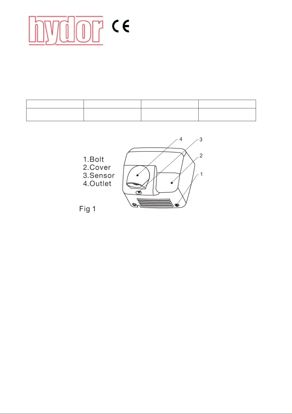
2.4 Refer to Fig. 4 and remove the cover from the base plate in sequence , , , and . Take
care not to put any strain on the connecting wires between the cover and base plate when
removing the cover.
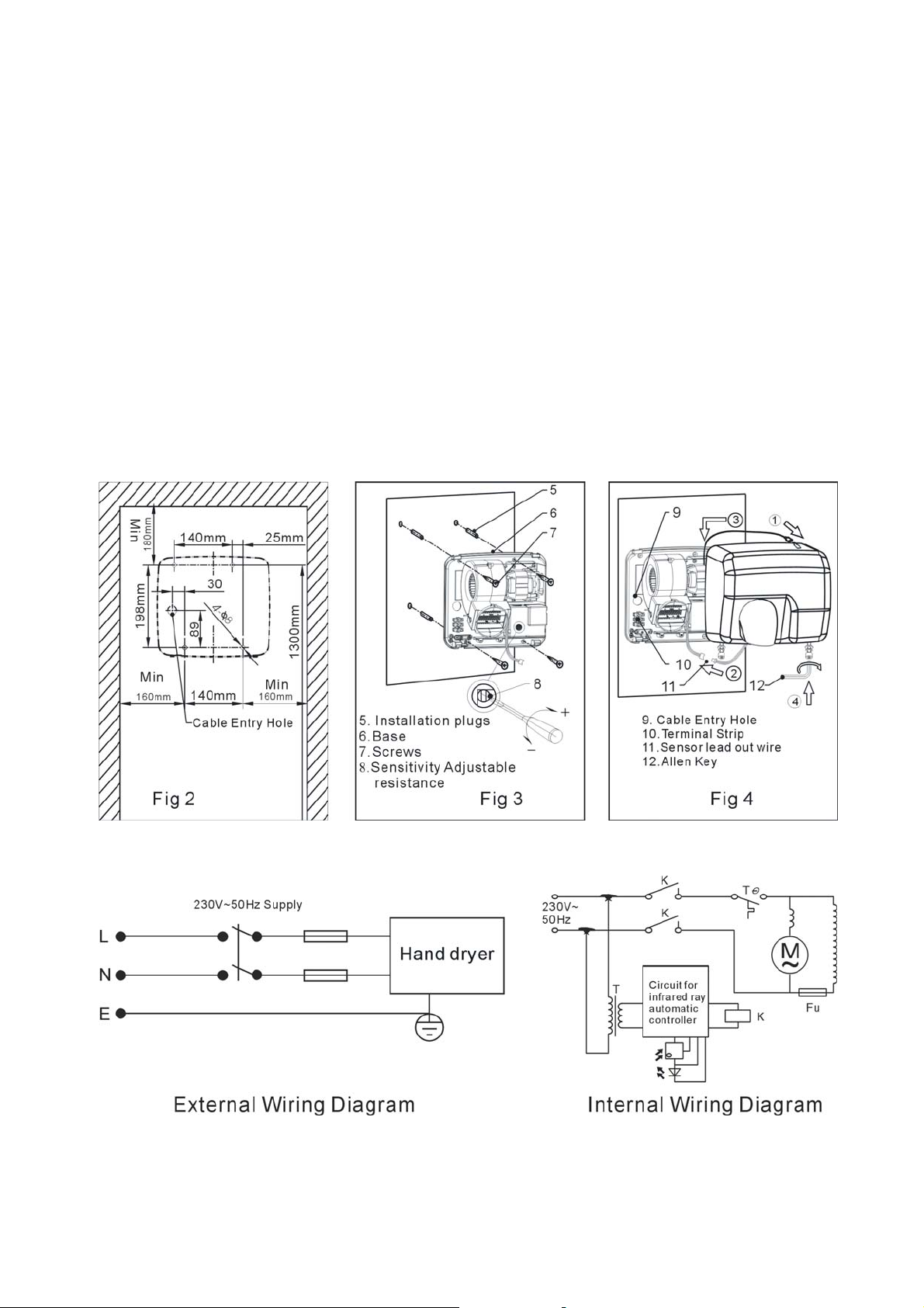
2.5 Mark and drill 8mm diameter by 35mm deep holes per Fig. 2.
2.6 Attach the base plate to the wall using the screws and plugs provided. Refer to Fig. 3.
2.7 Refer to the appropriate wiring diagram. Ensure that all earth connections are made.
2.8 Means for electrical disconnection must be incorporated in the wiring installation in accordance
with the relevant wiring and electrical regulations.
2.9 Fit the cover to the base plate per Fig. 4. Connect the earth wire to the cover. Connect the
sensor leads. Hook the cover to the top of the base. Push the cover and base firmly
together and fit the socket head machine screws using the Allen key provided.
Part No.: INST-HHD2500 02/12
 Loading...