

Hydor HCBI50, HCBI76, HCBI98 Installation And Maintenance Instructions Manual

HREI Inst Issue 1: 09.05.16
Installation and Maintenance Instructions.
THESE INSTRUCTIONS MUST BE READ FULLY BEFORE COMMENCING INSTALLATION.
Owner / installer: The life of this apparatus and its eciency will be increased if
its use and maintenance is carried out in accordance with these instructions and
current statutory requirements. The installation and initial adjustments should be
carried out by a qualified and competent technician. Hydor Limited should be
consulted before submitting or fitting parts from another manufacturer. It is the
responsibility of the installer to verify that the installation is in accordance with
the following standards and the owner is given the current User’s Manual.
Any modifications to the unit or its installation, even the smallest
modification, change or elimination of security components or pieces that
influence the eciency or loss of ventilation, will result in the CE Certification
and Hydor’s warranty being cancelled.
1. General
1.1 It is important these Installation and Maintenance Instructions are fully
adhered to.
1.2 Full details of the unit supplied are shown on the product nameplate. If in
doubt about any detail contact Hydor or its agents for clarification.
1.3 All electrical installation must be carried out by a suitably qualified
and competent personnel in accordance with all current statutory
requirements.
1.4 These instructions cover only the Hydor product and do not include the
supply or installation of safety equipment that may be required, e.g.
adequate protection and proper electrical isolation.
1.5 Any declarations made by Hydor about product installation and safety,
are dependent on other equipment being used within installation which
themselves meet the requirements of the Standards and Directives or your
region.
1.6 The heater is designed for use in an ambient temperature of up to
50C and up to 90% relative humidity. The unit is NOT suitable for corrosive
or explosive atmospheres.
HCBI Indirect Gas Fired Heater
incorrect
correct, minimum height 5mm
HREI Inst Issue 1: 09.05.16
1.7 The installer should provide easy access to the brooder to facilitate future
maintenance.
1.8 The installer should ensure the brooder is adequately supportedor
suspended .
1.9 This product is not intended for use by young children or infirm persons
unless they have been adequately supervised by a responsible person
to ensure that they can use the product safely. Young children should be
supervised to ensure that they do not play with the appliance.
WARNING The heater must be isolated from both the gas and power
supply during installation and maintenance. The fan must be earthed in
accordance with the local regulations.
2. Technical Characteristics
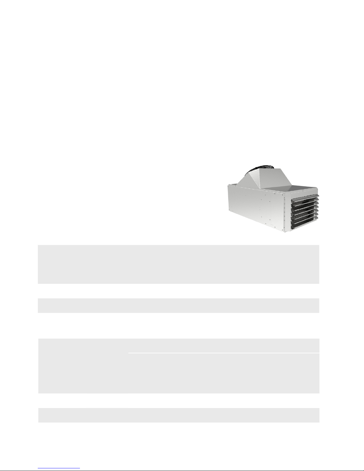
2.1 CBI Model. The HCBI heaters are equipped with
an axial fan. They are designed for direct
blowing into the room. They can be
suspended or equipped with supports for
installation on the floor.
2.2 Performance of CBI gas unit heater
Code
Throw
Gas Flow
Natural G20
20 mbar
(m³/h)
Groningen G25
25 mbar
(m³/h)
Propane 31
37 mbar
( kg/h)
HCBI50 30 5.29 5.88 3.91
HCBI76 35 8.04 8.94 5.93
HCBI98 40 10.58 11.76 7.81
Code
Calorific
Output
(kW)
Usable
power
(kW)
Eciency
(%)
Fan
(mm)
Speed
(r/min)
Air flow
(m³/h)
Delta T°
of the
air
(°C)
HCBI50 50 46 92 500 1350 4500 30
HCBI76 76 70 92 600 1350 6600 31.2
HCBI98 98 90.2 92 2 x 500 1380 9000 29.5
HREI Inst Issue 1: 09.05.16
Code
Smoke Exhaust
Diameter
(mm)
Air Inlet
Diameter
(mm)
Supply
Voltage
HCBI50 100 100
Single-phase 230 Volts / 50
Hz - IP54
HCBI76 130 130
HCBI98 130 130
Code
Electrical
Power
(W)
Electrical
Current
(A)
Operating
Temperature
(°C)
Weight
(kg)
HCBI50 470 2.1 0/+40 140
HCBI76 760 3.4 0/+40 200
HCBI98 890 4 0/+40 225
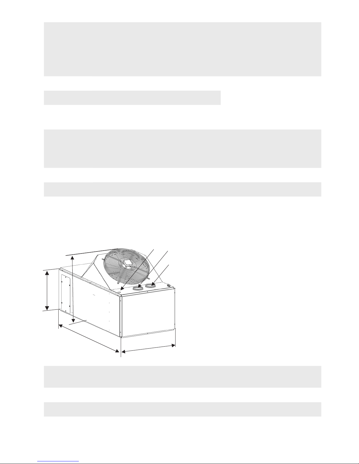
2.3 Dimensions
E
F
B
A
C D
G
Code
A B C D E F G
Weight
(kg)
HCBI 50 1791 638 617 1026 130 130 3/4’’ 140
HCBI 76 1791 892 617 1026 130 130 3/4’’ 200
HCBI 100 1791 1146 617 1026 130 130 3/4’’ 225

HREI Inst Issue 1: 09.05.16
2.3 The installer should ensure the heater is adequately supported or
suspended. Please refer to the following pages taking particular attention
regarding the dimension and weights.
2.4 This product is not intended for use by young children or infirm persons
unless they have been adequately supervised by a responsible person
to ensure that they can use the product safely. Young children should be
supervised to ensure that they do not play with the appliance.
WARNING The heater must be isolated from both the gas and the
power supply during installation and maintenance. The heater must be
earthed in accordance with the local regulations.
3. Installation
3.1 Upon receipt, the gas unit heater is delivered on a wooden pallet, plastic
film and cardboard packaging. This should be carefully removed and the
heater should be visually inspected to check for any damage. The unit is
normally supplied as a complete unit with accessories.
3.2 If there are any queries concerning the equipment,Hydor should be
contacted prior to the installation.
3.3 The HCBI heaters can be installed suspended from secure fixings or
supported on a suitable frame, fixed to the floor. They are designed to
blow directly into the room and are equipped with an axial fan.
3.4 Ensure there is free space around the heater and for ecient and safe
operation the following minimum distances must be adhered to:
3.4.1 A minimum space of 600mm above the fan intake.
3.4.2 A minimum space of 500mm around the heater.
3.4.3 A minimum distance of 1000mm above the floor.
3.4.4 Ensure there is sucient space behind the heater, to open the
burner door, of at least 900mm.
3.5 For a good functioning and the security of the device, it's necessary to
respect the minimum installation spaces here below:
3.5.1 Foresee a minimum space of 0,6 m above the unit (fan side).
3.5.2 Foresee sucient clearance for the opening of the burner door.
3.5.3 The heater must be installed at minimum 1 m from the floor.
3.5.4 No object can be placed at less than 0,5 m around the heater..

HREI Inst Issue 1: 09.05.16
0,6 m
6 m mini
1 m mini
0,9 m mini
0,5 m
0,5 m
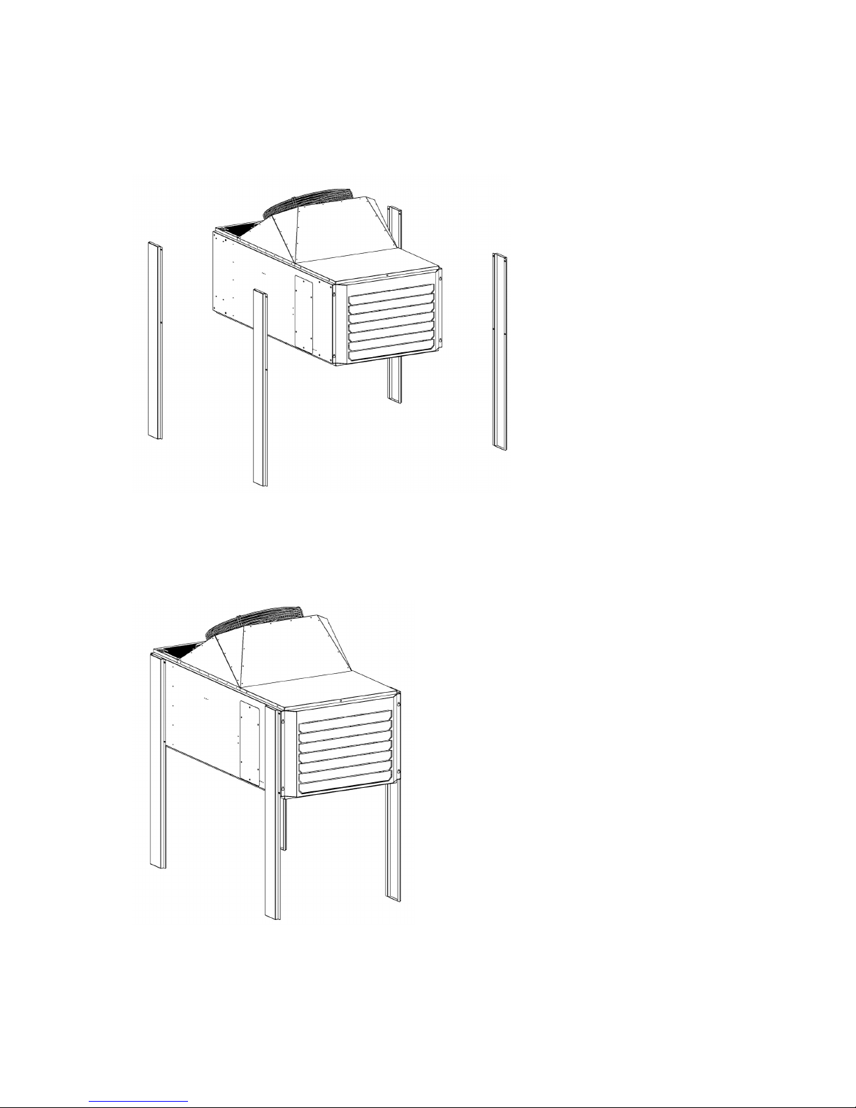
3.6 Suspended mounting: before mounting the device, it is necessary to
make sure of the support’s strength. The unit is equipped with 4 MS
threaded inserts on the top, to can be suspended. It is necessary to used
slings or threaded rods adapted to the weight of the unit. The mounting
must be perfectly aligned, as shown on the drawing here below.
Be careful, make sure to always use lock nuts to ensure the fastening.
HREI Inst Issue 1: 09.05.16
3.7 If the heater is to be suspended, it is necessary to make sure of the
support's strength. The heater is equipped with 4 - M8 threaded inserts
on the top of the unit. Ensure the slings or suspension rods are suitable
to take the weight of the heater model safely. These moutings must be
perfectly aligned with the unit, as per following drawing:
Present 4 feet and secure with screws M8.
3.7 If the heater is to be placed on feet, refer to the drawing below:
WARNING Support must be perfectly level, check the horizonal level
of the heater. Attach the feet to the ground to prevent it from being
moved unintentionally.
HREI Inst Issue 1: 09.05.16
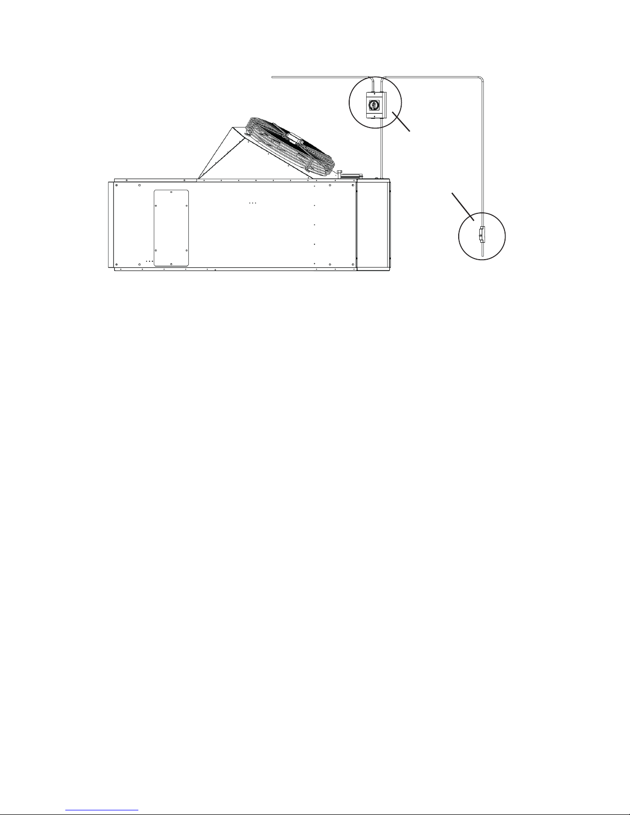
4. Electrical Connection and Control Regulation
4.1 The power supply is single-phase 230V/50Hz with a protected
electrical cable (1). The section of the cable and its protection must be
sized according to the number of units on the line and its length.
The regulation box will be connected to the gas heaters by a pilot wire.
Connect the regulator to the first heater, then connect the first heater to
second and proceed in the same for the others until the last one.
For people and equipment safety, it is recommended to install a switch
isolator (2). The connection must be realized by a qualified installer
following the diagram above.
Refer to the technical manual given with the regulation.
WARNING Be sure that general power supply is cut o before any
operation on the line. Electrocution hazard.
2
1
HREI Inst Issue 1: 09.05.16
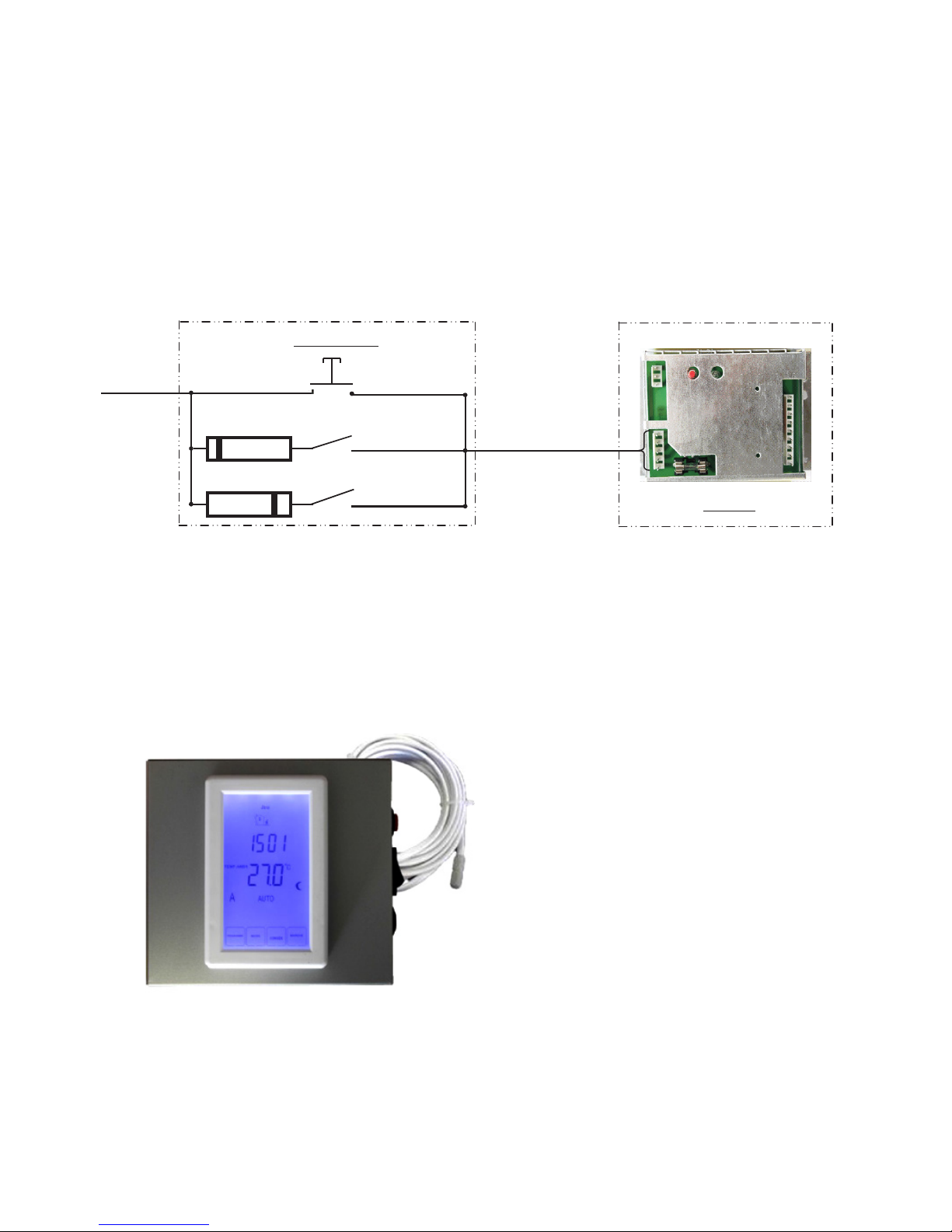
4.1 All gas heaters are equipped as standard with a pilot wire card.
The control sends a signal via the pilot wire, to the units equipped with the
pilot wire receptor (RFP card), which execute the operating order.
4.2 Four types of information are transmitted:
4.2.1 Heating demand
4.2.2 Ventilation only
4.2.3 Reset
4.2.4 Stop
4.3 Regular inspection of the brooder, should be carried out to ensure it is
operating correctly.
4.4 Thermostat with remote probe: Control box with programmable
touchscreen and remote probe. This regulation can manage up to 6
heaters. The use of a remote probe allows you to install the control box
outside the managed area. This box has also a default light which is
possible to connect. However, if the thermostat is connected to several
units, it is impossible to identify the one which has a defect.
REGULATION
HEATER
Reset
Pilot wire
Live
Diode
Diode
Heating
Ventilation
 Loading...