

Hyd-Mech VW18 Safety And Operating Instructions Manual
VW18
393349
Valid for machines from serial# JWA0113432B onward
THANK YOU,
On behalf of everyone at HYD·MECH Group Limited, we would like to thank and congratulate you on your decision to
purchase a HYD·MECH bandsaw.
Your new machine is now ready to play a key role in increasing the eciency of your operation, helping you to reduce cost
while boosting quality and productivity.
To ensure you are maximizing the power and versatility of your new HYD·MECH bandsaw, please take the time to
familiarize yourself and your employees with the correct operation and maintenance procedures as outlined in this
manual. Please keep this instruction manual for future reference in a known location and easily accessible to all users of
the device.
HYD·MECH oers a great variety of options, components, and features for its various models. Therefore, some of the
equipment described in this manual (various illustrations and drawings) may not be applicable to your particular machine.
The information and specications provided in this manual were accurate at the time of printing. HYD·MECH reserves the
right to discontinue or change specications or design at any time without notice and without incurring any obligation.
Thank you.
Hyd·Mech Group Limited
P.O. Box 1659, 1079 Parkinson Road
Woodstock, Ontario, N4S 0A9
Phone : (519) 539-6341
Service : 1-877-237-0914
Sales : 1-877-276-SAWS (7297)
Fax : (519) 539-5126
e-mail : info@hydmech.com
Printed March, 2016
1

TABLE OF CONTENTS
SECTION 0 - SAFETY INSTRUCTIONS
SUMMARY .......................................................................................................................................0.1
BASIC RULES ..................................................................................................................................0.3
RESPONSIBILITIES OF THE OWNER ............................................................................................0.3
RESPONSIBILITIES OF THE OPERATOR AND MAINTENANCE PERSONNEL ...........................0.4
SAFETY HAZARD LABELS .............................................................................................................0.6
LOCATION OF SAFETY HAZARD LABELS ON VW18 ...................................................................0.8
SECTION 1 - INSTALLATION
INSTALLATION ................................................................................................................................1.1
SAFETY PRECAUTIONS .................................................................................................................1.1
LIFTING AND SHIPPING .................................................................................................................1.2
FOUNDATION, LEVELLING AND ANCHORING .............................................................................1.2
RELOCATION OF INNER STOP SWING COLLARS (POWER TILT OPTION) ...............................1.3
CUTTING FLUID ..............................................................................................................................1.4
HYDRAULIC OIL ..............................................................................................................................1.4
WIRING CONNECTIONS .................................................................................................................1.4
RE-INSTALLING THE HEAD FORWARD/BACKWARD CYLINDER AND POTENTIOMETER. ......1.5
SECTION 2 - OPERATING INSTRUCTIONS
OPERATOR CONTROL PANEL .......................................................................................................2.1
START-UP ........................................................................................................................................2.1
CONTROL CONSOLE .....................................................................................................................2.2
OPERATION CONTROLS (STANDARD MACHINE) .......................................................................2.3
Manual Mode Machine Operation ....................................................................................................2.7
Setting Head Forward and Head Backward Limits ...........................................................................2.8
Cycle Parameter Display ..................................................................................................................2.8
Machine Parameters ........................................................................................................................2.8
Manual Head Swing .........................................................................................................................2.9
MACHINE ALARMS AND EMERGENCIES ....................................................................................2.10
SETTING THE HEAD LINEAR POTENTIOMETER (LIMITS RHLS/FHLS) ....................................2.10
OPERATION CONTROLS (POWER TILT OPTION) .......................................................................2.11
STARTING THE MACHINE (POWER TILT OPTION) .....................................................................2.17
CYCLE PARAMETER DISPLAY (POWER TILT OPTION) ..............................................................2.18
SETTING HEAD UP AND HEAD DOWN LIMITS (POWER TILT OPTION) ....................................2.18
MANUAL MODE: Machine Operation (POWER TILT OPTION) ......................................................2.19
SEMI-AUTOMATIC MODE: Machine Operation (POWER TILT OPTION) ......................................2.21
CUT IN SEMI-AUTOMATIC MODE (POWER TILT OPTION) .........................................................2.22
MACHINE PARAMETERS (POWER TILT OPTION) .......................................................................2.25
3º CANTED HEAD ..........................................................................................................................2.27
HYDRAULIC FEED CONTROL .......................................................................................................2.33
CUTTING PARAMETERS CHART ..................................................................................................2.34
GUIDE ARM POSITION ..................................................................................................................2.40
COOLANT FLOW ............................................................................................................................2.41
i

SECTION 3 – MAINTENANCE & TROUBLESHOOTING
SAFETY DURING MAINTENANCE .................................................................................................3.1
LOCK OUT PROCEDURE ...............................................................................................................3.1
BLADE CHANGING PROCEDURE .................................................................................................3.3
BLADE TRACKING ..........................................................................................................................3.5
DRIVE WHEEL TRACKING ADJUSTMENT ....................................................................................3.5
IDLER WHEEL TRACKING ADJUSTMENT .....................................................................................3.6
BLADE BRUSH ...............................................................................................................................3.6
BLADE GUIDES ...............................................................................................................................3.7
HYDRAULIC MAINTENANCE ..........................................................................................................3.7
GEARBOX LUBRICATION ...............................................................................................................3.7
LUBRICATION ..................................................................................................................................3.8
MEP31 AND MEP32 CONTROLLER: TROUBLESHOOTING .........................................................3.9
RE-SETTING 90 DEGREE REFERENCE OF ANGLE ENCODER (POWER TILT OPTION) .........3.14
SECTION 4 - ELECTRICAL
ELECTRICAL SCHEMATICS: SEE PDF ON ATTACHED CD .........................................................4.1
SECTION 5 - HYDRAULIC
HYDRAULIC SCHEMATICS & PLUMBING DIAGRAMS: SEE PDF ON ATTACHED CD ...............5.1
SECTION 6 - MECHANICAL ASSEMBLIES
MECHANICAL ASSEMBLY DRAWINGS & PARTS LIST: SEE PDF ON ATTACHED CD ................6.1
SECTION 7 - OPTIONS
OPTIONAL ASSEMBLY DRAWINGS: SEE PDF ON ATTACHED CD .............................................7.1
SECTION 8 - SPECIFICATIONS
VW18 SPECIFICATIONS LIST ........................................................................................................8.1
VW18 LAYOUT .................................................................................................................................8.2
SECTION 9 - WARRANTY
WARRANTY .....................................................................................................................................9.1
ii

SECTION 0 - SAFETY INSTRUCTIONS
SUMMARY
All persons operating this machine must have read and understood all of the following sections of this Manual:
Section 0 SAFETY
Section 2 OPERATING INSTRUCTIONS
However, as a memory aid, the following is a summary of the Safety Section.
Put Safety First
Mandatory Information – What operators and maintenance people must have read and understood.
Signatures – Everyone involved with this machine must sign to conrm they have read and understood mandatory infor-
mation.
Basic Rules – only use this machine when
• It is in good working order.
• All safety equipment is in place and functional.
• Operations are in compliance with this manual.
• Materials are within designed specications and are non-hazardous.
Owner is responsible to
• Keep Manual accessible at the machine.
• Ensure only reliable, fully trained personnel work with the machine.
• Clearly dene responsibilities of all personnel working with the machine.
• Keep the machine in good working order.
Operator and Maintenance Personnel are responsible to:
• Keep all safety equipment in order, check its function at the beginning of each shift, and report any shortcomings.
• Shut down machine and report any faults or malfunctions that could impair safety.
• Understand and obey safety hazard labels.
• Not to wear un-restrained long hair, loose clothing or jewelry.
• Wear all required personal protective equipment.
• Not to wear gloves within 24 inches of moving blade.
• Maintain a clean working area and machine.
• Always use Lock-out when performing maintenance or repairs.
0.1

FOREWORD
Put Safety First!
This Safety Section contains important information to help you work safely with your machine and describes the dangers
inherent to bandsaws. Some of these dangers are obvious, while others are less evident.
It really is important to PUT SAFETY FIRST. Make it a habit to consider the hazards associated with any action BEFORE
you do it. If you feel any uncertainty, stop and nd a safer approach to the action. If you’re still uncertain, ask for advice
from your supervisor.
The SAFETY FIRST approach is particularly necessary when you do something new, or dierent, and most people instinctively recognize this, although impatience may still cause them to take unnecessary risks.
Danger also lurks in the routine task that we have done over and over. Here, familiarity, boredom, or tiredness may lull us
into unthinking, automatic repetition. Be alert for this, and when you feel it happening, stop and take stock of your
situation. Review the safety hazards associated with what you are doing. That should get your brain working again.
Certainly production is important, but if you think you’re too busy to put safety rst, think how much production you’ll lose if
you get hurt.
You owe it to yourself, your family, and your co-workers to PUT SAFETY FIRST.
Mandatory Information
All persons operating this machine must have read and understood all of the following sections of this Manual:
Section 0 SAFETY
Section 2 OPERATING INSTRUCTIONS
Personnel involved in installation and maintenance of the machine must have read and understood all sections of the
manual
Persons who have diculty reading, or for whom English is not their rst language, must receive particularly thorough
instruction.
Signatures
Everyone involved in operation of this machine must sign below to conrm that:
I have read and understood all parts of Section 0 – Safety, and Section 2 – Operating Instructions.
Name Date Signature
Everyone involved in the installation, inspection, maintenance, and repair of this machine must sign below to conrm that:
I have read and understood all parts of this Operation and Maintenance Manual.
Name Date Signature
0.2

BASIC RULES
Intended Use
Exclusion of Misuse
Liability
Our machines are designed and built in line with the state of the art, and specically in accordance with
American National Standards Institute Standard B11.10 Safety Requirements for Metal Sawing Machines.
However, all machines may endanger the safety of their users and/or third parties, and be damaged,
or damage other property, if they are operated incorrectly, used beyond their specied capacity, or for
purposes other than those specied in this Manual.
Misuse includes, for example:
Sawing hazardous materials such as magnesium or lead.
Sawing work pieces which exceed the maximum workload appearing in the Specications.
Operating the machine without all original safety equipment and guards.
The machine may only be operated:
When it is in good working order, and
When the operator has read and understood the Safety and Operating Instructions Sections of the
Manual, and
When all operations and procedures are in compliance with this Manual.
Hyd-Mech Group cannot accept any liability for personal injury or property damage due to operator errors
or non-compliance with the Safety and Operating Instructions contained in this Manual.
RESPONSIBILITIES OF THE OWNER
Organization of work
This Operation and Maintenance Manual must always be kept near the machine so that it is accessible to
all concerned.
The general, statutory and other legal regulations on accident prevention and environmental protection
must also be observed, in addition to the Manual material. The operators and maintenance personnel
must be instructed accordingly. This obligation also includes the handling of dangerous substances and
the provision and use of personal protective equipment.
Choice and qualication of personnel
Ensure that work on the machine is only carried out by reliable persons who have been appropriately
trained for such work.
Training
Everyone working on or with the machine must be duly trained with regard to the correct use of the
machine, the correct use of safety equipment, the foreseeable dangers that may arise during operation of
the machine, and the safety precautions to be taken.
In addition, the personnel must be instructed to check all safety devices at regular intervals.
0.3

Dene responsibilities
Clearly dene exactly who is responsible for operating, setting-up, servicing and repairing the machine.
Dene the responsibilities of the machine operator and authorize him to refuse any instructions by third
parties if they run contrary to the machine’s safety.
Persons being trained on the machine may only work on or with the machine under the constant
supervision of an experienced operator. Observe the minimum age limits required by law.
Condition of Machine and Workplace
Ensure that the machine and its safety equipment are kept in good working order.
Ensure that the work area is well lit, and protected from the elements, such as rain, snow, abrasive dust,
and extremes of temperature.
Ensure that the machine is installed with sucient clearance around it for the safe loading and unloading
of work pieces.
RESPONSIBILITIES OF THE OPERATOR AND MAINTENANCE PERSONNEL
Safety equipment
All machines are delivered with safety equipment that must not be removed or bypassed during operation.
The correct functioning of safety equipment on the machine must be checked:
• At the start of every shift.
• After maintenance and repair work
• When starting for the rst time, and after prolonged shutdowns
Emergency Stop Button (E-Stops)
Always be aware of the location of the Emergency Stop Button(s). Do not allow material or objects to
block your access to an Emergency Stop.
Damage
If any changes capable of impairing safety are observed in the machine or its operation, such as damage,
malfunctions, or irregularities, then appropriate steps must be taken immediately, the machine switched
o, locked-out, and the fault reported to the responsible person.
Safe operation
The machine may only be operated when in good working order and when all protective equipment is in
place and operational.
Keep a safe distance from all moving parts – especially the blade and vises.
Stock should not be loaded onto the saw if the blade is running.
Long and heavy stock should always be properly supported in front of and behind the saw.
Faults
The machine must be switched o and locked-out before starting to remedy any faults.
Safety hazard labels
Safety hazard labels and other instructional labels on the machine must be observed. They must be
clearly visible and legible at all times. If they become damaged they must be replaced.
0.4

Clothing, jewelry, protective equipment
Personnel operating or working on the machine must not wear un-restrained long hair, loose-tting
clothes and dangling jewelry.
When operating or working on the machine, always wear suitable, ocially tested personal protective
equipment such as safety glasses and safety boots and any other equipment required by plant
regulations.
Gloves
Experience has shown that careless use of gloves around machinery is a major factor in serious hand
injuries.
Gloves should not be worn when operating or adjusting the machine, except:
Wear protective gloves when handling bandsaw blades at blade changes.
Gloves may be worn when handling work pieces, only if the machine is in Manual Mode and the
bandsaw blade is not running.
If the machine is running in Auto Mode, and only if the cut parts are greater than 24 inches
long, it may be possible to safely wear gloves for handling the cut parts, but the wearer of the
gloves must never put his hands near the blade for any reason. If the cut parts are less than 24
inches long, it is required to arrange their automatic ow into a parts bucket or other suitable
arrangement to avoid the necessity to pick them o the machine by hand.
Hearing protection
Ear protection must be worn whenever necessary.
The level and duration of noise emission requiring hearing protection depends upon the national regulations in the country in which the machine is being used.
The actual level of noise emission by band sawing machines depends upon work piece size, shape and
material, blade type, blade speed and feed rate.
The only practical course of action is to measure the actual noise emission levels for the type of work that
is typically done. With reference to national standards, decide upon the necessary hearing protection
required.
In the absence of such measurements, it is advisable for anyone exposed to long periods of moderate to
loud noise to wear hearing protection. It is important to understand that hearing loss is gradual and easily
goes un-noticed until it is serious and irreversible.
Workplace
A clear working area without any obstructions is essential for safe operation of the machine. The oor
must be level and clean, without any build-up of chips, o-cuts, coolant, or hydraulic oil.
The workplace must be well lit, and protected from the elements, such as rain, snow, abrasive dust, and
extremes of temperature
Nothing may ever be placed on, or leaned against the machine, with the obvious exception of the work
piece on the table and conveyor of the machine.
0.5

Master Disconnect
Lock-out the machine before undertaking any maintenance or repair work on it. ‘Lock-out’ refers switching
o the master electrical disconnect switch, and locking it out so that it cannot be switched on again
without authorization.
On Hyd-Mech machines the Master Disconnect Switch will be of one of four types:
• Rotary switch mounted in electrical control cabinet door and inter-locked with door.
• Rotary switch mounted on the side of the operator interface console.
• Lever switch mounted in separate box mounted on the machine.
• Supply disconnect switch supplied by user at installation and usually wall-mounted within sight of
the machine, depending upon local regulations.
In almost all jurisdictions, it is required that owners of industrial equipment establish and post
lock-out procedures. Know and use the lock-out procedures of your company or organization.
Residual Risks
The machine is still not completely de-energized if an electrical cabinet door type switch is
locked-out.
The line side of the disconnect switch itself remains energized.
Variable speed blade drives store dangerous voltage in their capacitors, and this requires time to
dissipate. After locking out power, wait 3 minutes before beginning to work on machine electrical
circuits.
If compressed air is supplied to the machine to power a mist lubrication system or other devices,
it should be disconnected, and any stored air pressure released before working on the machine.
The weight of individual machine components represents stored potential energy that can be
released if they fall when disconnected. Secure these components with adequate hoisting gear
before disassembly.
SAFETY HAZARD LABELS
The safety hazard labels attached to your machine represent important safety information to help you avoid personal injury
or death.
All supervisors, operators, and maintenance personnel must locate and understand the safety information associated with
each hazard label prior to operating or servicing the machine.
The safety hazard labels shown below are located at various positions on the machine to indicate possible safety hazards.
The location and re-order part number of all the safety labels associated with this particular model of bandsaw are indicated
at the end of this section of the manual. It is important to replace any safety hazard label that becomes damaged or illegible.
HAZARDOUS VOLTAGE INSIDE
Contact with high voltage may cause death or serious injury. Never perform
maintenance on, or near, electrical components until the machine’s electrical
power source has been disconnected. Lock-out power in accordance with your
company’s lock-out procedures before any such maintenance. The “Stop” or
“Emergency Stop” push button does not disconnect the machine’s power supply.
Hazardous voltage is still present in the machines electrical circuits.
The machine’s Electrical Disconnect Switch does disconnect voltage from the
machine’s circuits; however hazardous voltage is still present inside the main electrical cabinet, on the infeed (line) side of
the main fuses. Therefore keep hands and tools away from the infeed side of the control panel main fuses. If these fuses
need to be replaced, use a fuse puller.
Allow three minutes after locking-out power before opening any electrical enclosures. Your machine may be equipped with a
variable frequency drive that stores high voltage within its capacitors. Three minutes will allow sucient time for this voltage
to safely discharge.
Never spray coolant directly at electrical components or cabinets.
0.6
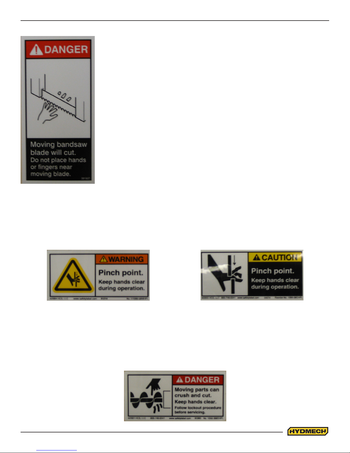
PINCH POINT
MOVING BANDSAW BLADE WILL CUT
Do NOT operate with guard removed.
Do NOT place hands or ngers near moving bandsaw blade.
For blade changing, always follow the proper Blade Changing Procedure, as given in
Section 3 of this manual.
Machine parts may move without warning, either because the machine is operating automatically, or because another
person initiates the motion. Keep hands clear of all labelled pinch points, whenever the machine is running. Machine vises
can exert great force and cause severe injury. Keep hands clear of vises and work piece when vises are opened or closed.
Be aware that vise closing or opening may result in potentially dangerous work piece movement. Be aware also that the
opening motion of a vise may create potential pinch points.
MOVING PARTS CAN CRUSH AND CUT
Keep hands clear of chip auger. Lock-out power in accordance with your company’s lock-out procedures before attempting
to clear a jam in the chip auger.
Be aware that the chip auger may start unexpectedly, either because the machine is operating automatically, or because
another person initiates the motion.
If the chip auger is stalled because of a jam, it may start without warning when the jam is cleared, unless the machine power
is locked out.
0.7
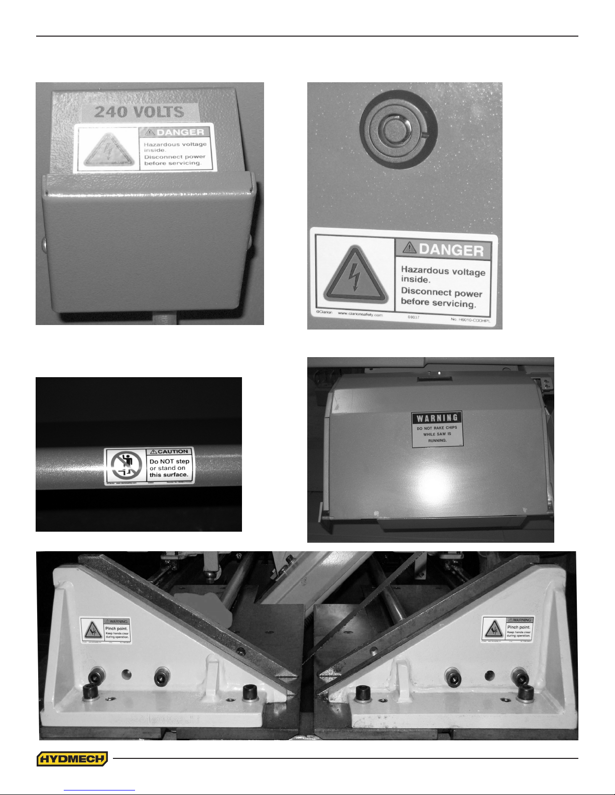
LOCATION OF SAFETY HAZARD LABELS ON VW18
Power Junction Box Electrical and Hydraulic panel lock.
Coolant shroud
Drive wheel Door
0.8

SECTION 1 - INSTALLATION
INSTALLATION
Upon delivery of your new VW18 saw, it is imperative that a thorough inspection be undertaken to check for any damage
that could have been sustained during shipping. Special attention should be paid to the electrical and hydraulic systems to
check for damaged cords, hoses and uid leaks. In the event of damage caused during shipping, contact your carrier to le
a damage claim.
SAFETY PRECAUTIONS
The VW18 has been designed to give years of reliable service. It is essential that operators be alerted to the safe
operation of this saw, and the practices to avoid that could lead to injury. The following safety rules are at the minimum
necessary for the safe installation, operation, and maintenance of the saw. Take every precaution for the protection of
operators and maintenance personnel.
• POWER HOOK-UPS AND REPAIRS SHOULD BE ATTEMPTED ONLY BY QUALIFIED TRADESMEN.
• THE SAW SHOULD BE LOCATED IN AN AREA WITH SUFFICIENT ROOM TO SAFELY LOAD STOCK INTO
THE SAW. SECURE THE SAW TO THE FLOOR.
• THE AREA AROUND THE SAW SHOULD BE MAINTAINED IN A CLEAN AND TIDY CONDITION TO AVOID
OBSTACLES OPERATORS COULD TRIP OVER.
• THE VW18 SHOULD ONLY BE OPERATED ACCORDING TO THE SPECIFICATIONS OF THE SAW. AVOID
UNSAFE USAGE PRACTICES.
• IF AT ANY TIME THE SAW DOES NOT APPEAR TO BE OPERATING PROPERLY IT SHOULD BE STOPPED
IMMEDIATELY AND REPAIRED.
OPERATOR:
• THE SAW SHOULD NEVER BE OPERATED UNLESS ALL GUARDS AND DOORS ARE IN PLACE AND
CLOSED.
• KEEP A SAFE DISTANCE FROM ALL MOVING PARTS - ESPECIALLY THE BLADE AND VISES.
• LOOSE CLOTHING AND GLOVES SHOULD NEVER BE WORN WHILE OPERATING THE SAW. COVER LONG
HAIR.
• STOCK SHOULD NOT BE LOADED ONTO THE SAW IF THE BLADE IS RUNNING.
• LONG AND HEAVY STOCK SHOULD ALWAYS BE PROPERLY SUPPORTED IN FRONT OF AND BEHIND THE
SAW.
• NEVER ATTEMPT TO DISLODGE OR MOVE STOCK WHILE THE BLADE IS MOVING. TAKE THE TIME TO
STOP THE SAW BLADE, REMOVE OBSTRUCTIONS, AND RESTART BLADE.
• MUST WEAR EYE PROTECTION
• MAINTAIN PROPER ADJUSTMENT OF BLADE TENSION, AND BLADE GUIDES
• HOLD WORK PIECE FIRMLY AGAINST TABLE
• DO NOT REMOVE JAMMED CUTOFF PIECES UNTIL BLADE HAS STOPPED
NO MODIFICATIONS TO THE MACHINE ARE PERMITTED WITHOUT PRIOR APPROVAL FROM HYD-MECH. ANY
APPROVED MODIFICATIONS SHOULD ONLY BE UNDERTAKEN BY TRAINED PERSONNEL.
1.1
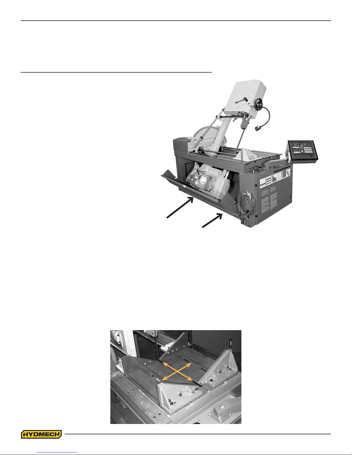
LIFTING AND SHIPPING
To lift a VW18 bandsaw with a forklift, it must meet the following minimum requirements;
Capacity of 2800 lb (1270 kg.) at 48”(122 cm) from the mast, as well as 6’ (183cm) long forks.
The machine should be lifted from under the base, at either side as shown below.
(Head should be at 90º position before attempting to pick up machine)
FOUNDATION, LEVELLING AND ANCHORING
Machine location should be carefully selected. A at concrete oor area should be chosen. It should have enough free
space surrounding the machine to enable free access for safe operation and maintenance. The machine should be
leveled in both directions (from side to side & from front to back). Four leveling screws used for securing the machine to
the pallet during transport, should be installed, one in each corner of the machine base. It might be required to place steel
plates under leveling bolts to prevent their sinking into the concrete oor. In cases when the machine is to be anchored
permanently, anchoring holes are provided. They are located next to the leveling screw holes. The larger diameter hole
is used for retaining during shipping and for use with concrete oor anchors. The smaller diameter threaded hole at each
corner, are used for leveling the saw.
Using a level on the machine out-feed table, level machine front to back and side to side.
NOTE: In some cases leveling the saw infeed with a slight slope towards the blade is recommended. This will prevent
coolant from running down the raw stock. (This is especially true when cutting tubing or bundles).
1.2
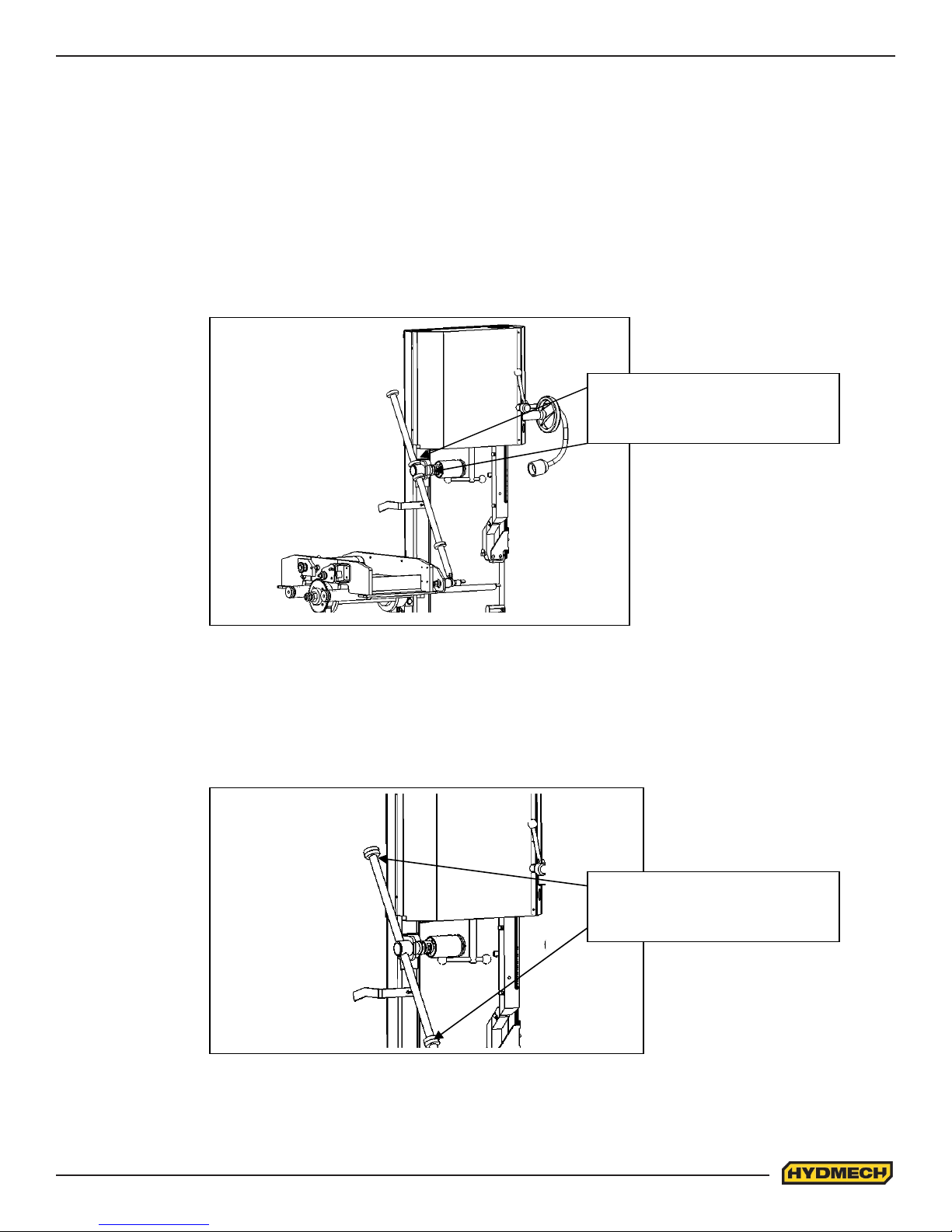
RELOCATION OF INNER STOP SWING COLLARS (POWER TILT OPTION)
For shipment inner stop swing collars should be relocated and locked against brake assembly as
shown on Fig. 1
Inner Collars relocated for
Shipment
Fig. 1
After installation collars should be moved back to original location against outside collars and
locked as shown on Fig. 2
Location of inner collars for
Machine normal operation
Fig. 2
1.3
CUTTING FLUID
The VW18 uses a pump and reservoir to circulate the necessary cutting uid to the blade for maximum blade life. Your
saw blade supplier will be able to provide information to the cutting uid products that are available for your needs.
No cutting uid (coolant) is supplied with the machine. There are two types of coolant available:
- Oil based; dilute 1:10 ratio (one part concentrated coolant to 10 parts water)
- Synthetic; dilute as recommended by manufacturer.
HYDRAULIC OIL
The VW18 is supplied with Texaco Rando HD46 hydraulic oil. Substitutes should be of the same viscosity hydraulic oil.
WIRING CONNECTIONS
After the machine is leveled and anchored the necessary power hook-up needs to be performed.
Check that there is no sign of shipping damage to the electrical conduits, cords or hydraulic hoses.
As supplied, the VW18 is built to run on three phase AC Voltage, as indicated on the machine serial plate and voltage
label. Machine voltage is customer specic and should be indicated while ordering the machine. If machine voltage does
not match available power source contact factory.
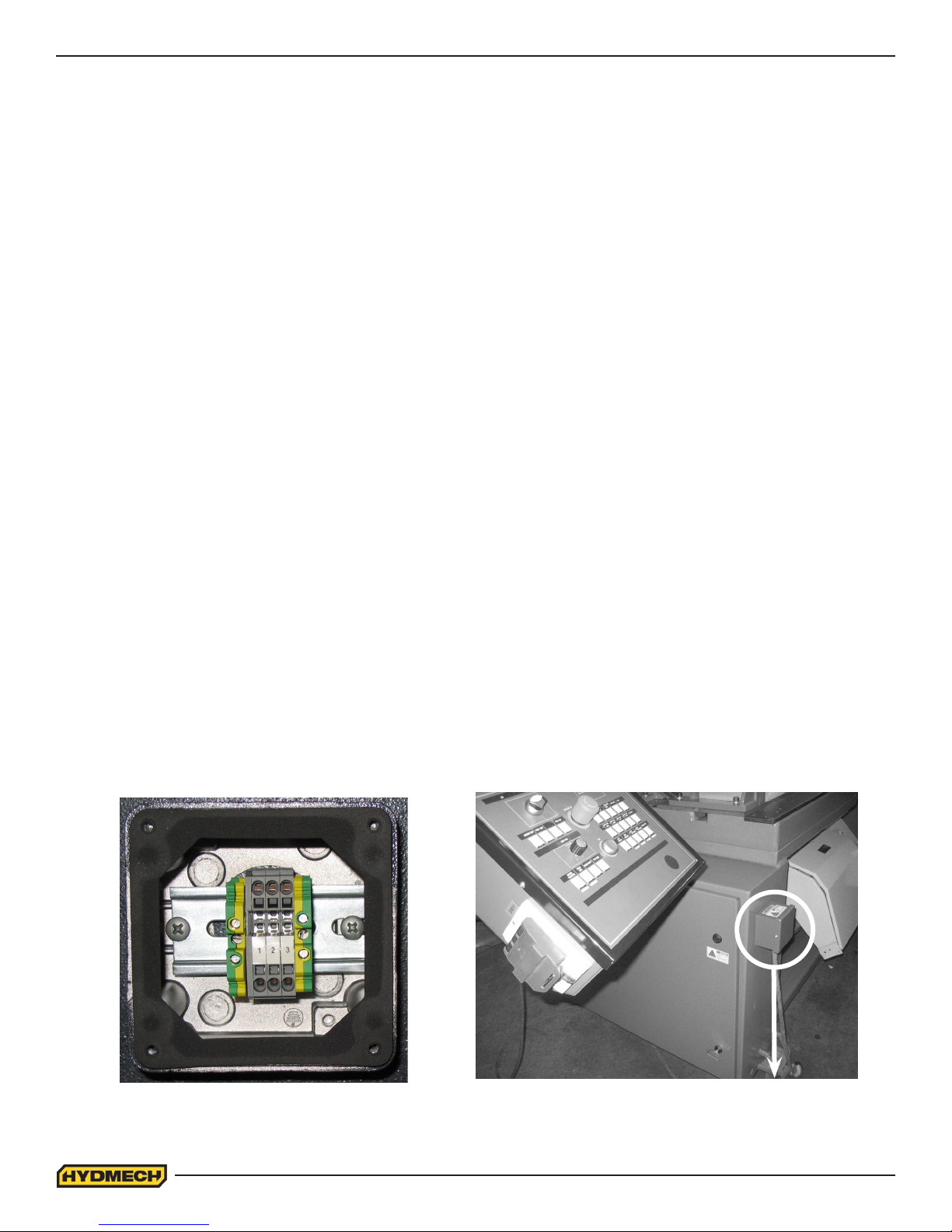
Power connection to the machine is made in the junction box, located on the side of the electrical and hydraulic panel.
The power cable can be routed through the supplied hole in the junction box, and connections made to L1, L2, L3, and
ground terminals. Proper strain relief should be used on the incoming power cable.
Power Junction Box
Power Junction Box
1.4
RE-INSTALLING THE HEAD FORWARD/BACKWARD CYLINDER AND POTENTIOMETER.
To prevent damage to the Head cylinder and potentiometer during shipping, the two items have been
secured for shipping purposes. For machine operation the head cylinder and potentiometer have to be
re-installed as described in the following steps.
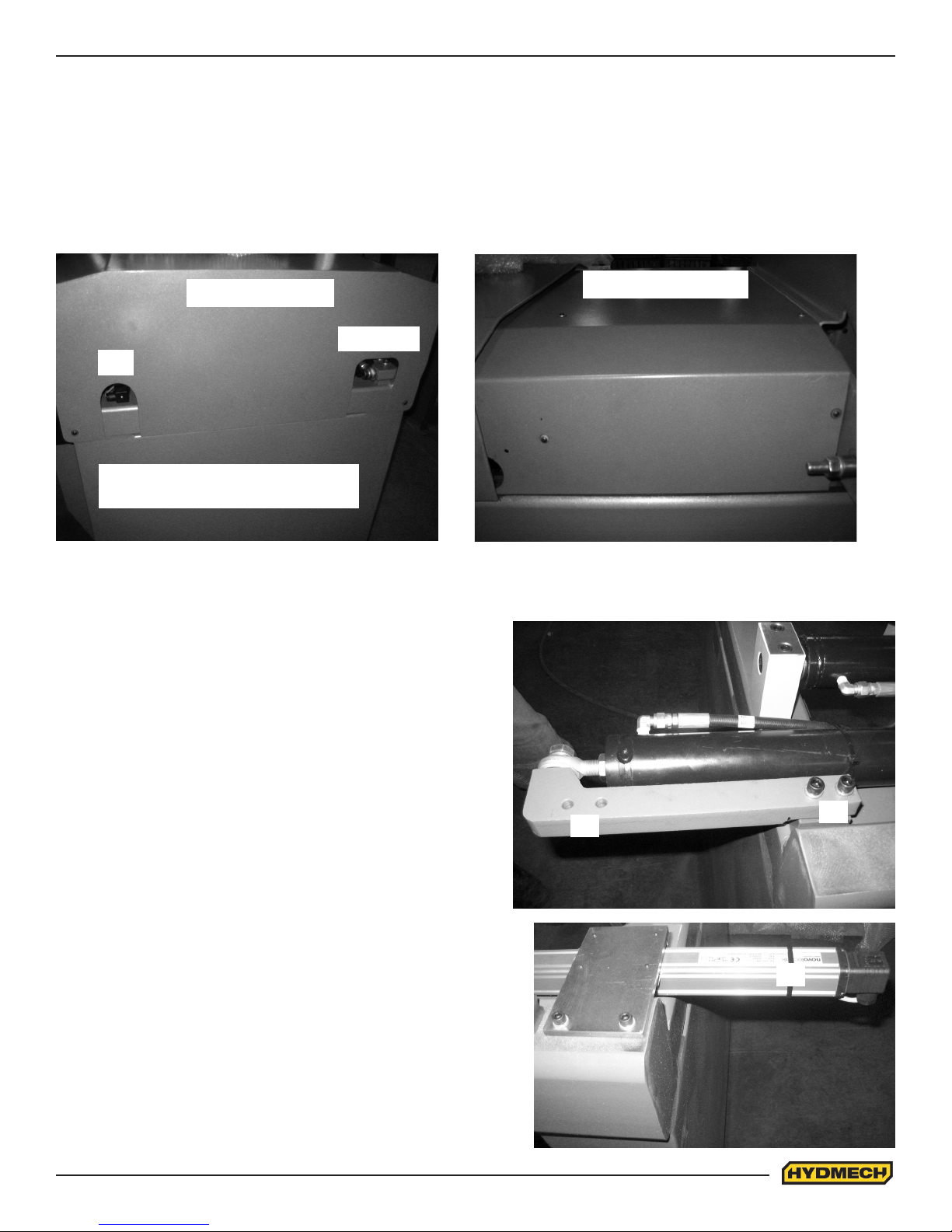
STEP ONE
Remove the top covers of the carriage by removing the front carriage cover rst and then the back carriage cover.
Back carriage cover
CYLINDER
POT
Remove all 10-24 SHCS with a 3/16
allen key from the carriage covers
View from the back of the machine.
STEP TWO
Once the covers are removed you will see the Head Cylinder
and the Head Potentiometer. To move the head cylinder:
1. Remove the two 1/2” SHCS which are located at ‘A’ with a
3/8” allen key.
Front carriage cover
View from the side of the machine.
2. Move the bracket and cylinder out and insert the two
1/2” SHCS at ‘B’ as the picture indicates and tighten.
STEP THREE
1. Cut the zip ties except for ‘A’.
2. Move bracket to the position shown in the picture.
3. Insert and tighten the 10-24 SHCS with a 3/16 allen key.
A
B
A
1.5
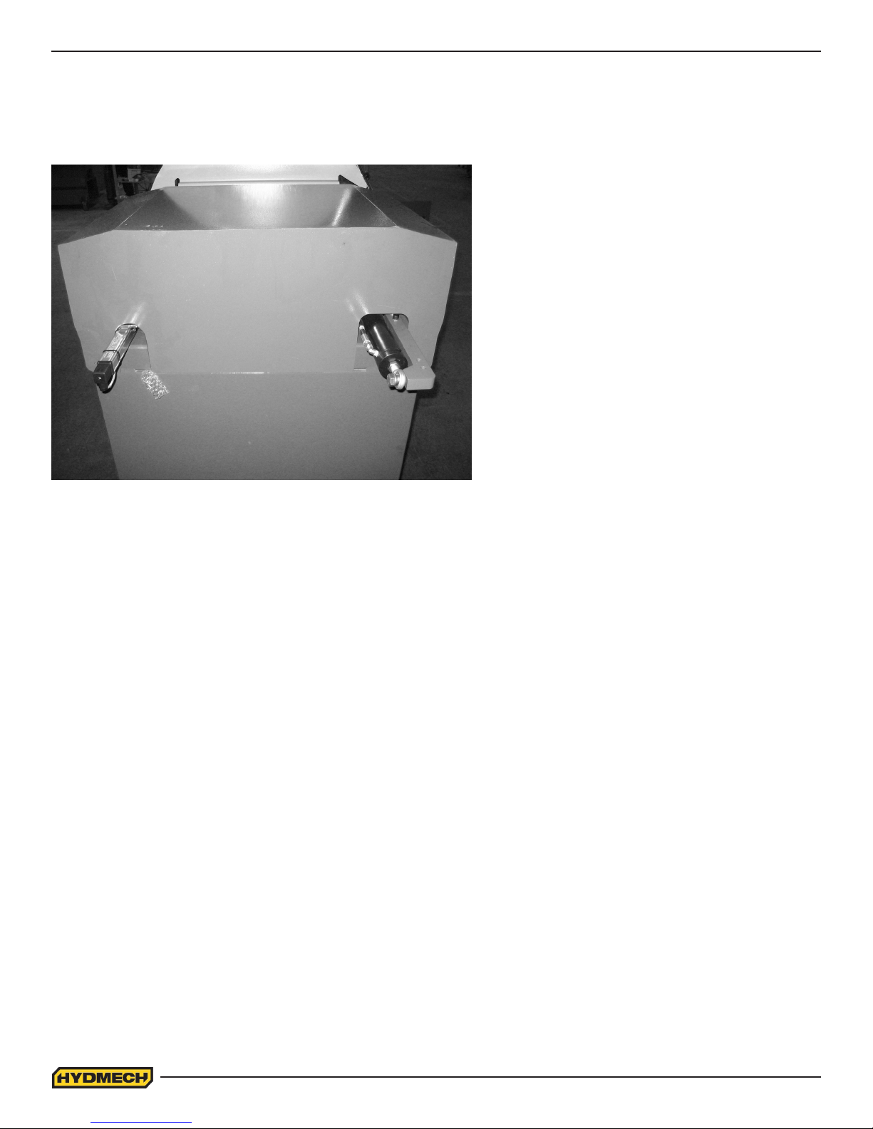
STEP FOUR
Install the back carriage cover and install all the 10-24 SHCS with a 3/16 allen key.
Install the front carriage cover and install all the 10-24 SHCS with a 3/16 allen key.
View of the head potentiometer and cylinder after re-installation.
1.6
SECTION 2 - OPERATING INSTRUCTIONS
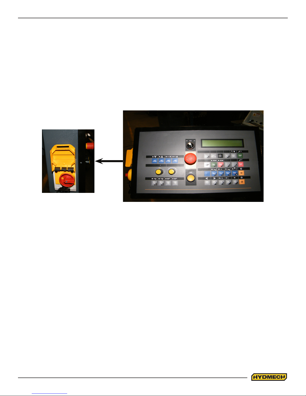
OPERATOR CONTROL PANEL
The operator control panel provides the operator with all the controls necessary to operate the saw after the cutting angle
has been set and the stock has been loaded and secured. All of the electrical functions are operated from the control
panel. For all the functions to work the machine has to be powered up. The Main Disconnect switch, which is located
on the side of control box, has to be in ON (1) position. Emergency Switch has to be released (Rotate Emergency button
45º to release). For the blade to operate the blade door has to be completely shut and blade tensioned to minimum
tension of 1320 lbs (600 kg) maximum tension of 2650 lbs (1202 kg)
POWER TILT OPERATOR PANEL SHOWN
The Machine Disconnect Switch is located on the side on the machine control box. It is a Thermal-magnetic circuit
breaker with under voltage coil and door locking device. The switch consists of three power failure protection
systems. In the event of a power failure, this switch disconnects all the electrical devices, causing the machine to
immediately shut down and prevents it from automatically starting when power is restored. This device also resets the
thermal relay tted to protect against current overloads.
START-UP
The VW18 control console has been designed to simplify the operation of the saw, to give the operator the ability to stop
any function at any time, and to be able to control all the functions remotely.
We cannot overstress the importance of familiarizing yourself with the controls prior to star ting the machine.
NOTE: WHEN STARTING THE VW18 FOR THE FIRST TIME MAKE SURE THAT THE HYDRAULIC PRESSURE
IS 450 - 500 ± 25 PSI AND THAT THE BLADE IS RUNNING IN A COUNTERCLOCKWISE DIRECTION AS VIEWED
FROM THE DOOR SIDE THE OF HEAD.
IF THERE IS NO IMMEDIATE PRESSURE, SHUT THE SAW DOWN AND CHANGE THE PHASE ORDER.
2.1
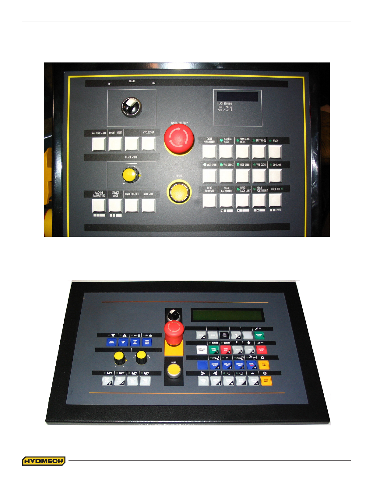
CONTROL CONSOLE
The control console is arrayed with a complete set of controls to operate the electrical and hydraulic functions of the saw.
The HMI (Human Machine Interface) consists of all, the electrical controls required to function the saw.
STANDARD OPERATOR PANEL
POWER TILT OPERATOR PANEL
2.2

OPERATION CONTROLS (STANDARD MACHINE)
The electrical buttons on the control panel allow for full manual and semi-automatic operation of the VW18. The operation
of each button is detailed on the following pages.
BLADE OFF (0) - ON (1):
• This selector switch must be in the ON (1) position for the BLADE ON/OFF push-button to function.
MACHINE START:
• Starts the hydraulic pump motor.
• Machine disconnect switch must be in “ON” position.
• When the hydraulic pump is idle for a period of time the pump will shut down. The pump will start up
again when any hydraulic function is activated. I.e. Head Forward, Left Vise Open.
COUNT RESET:
• Resets the number of pieces cut to 0 (Zero) on the LCD display.
CYCLE PAUSE:
• In MANUAL MODE and SEMI-AUTO MODE, if CYCLE PAUSE is depressed the cycle pauses.
(The HEAD will STOP but the BLADE will continue to RUN)
• To continue the cycle, depress CYCLE START push button.
BLADE SPEED DIAL:
• This dial controls the blade speed which can be adjusted between 65 and 385 SFM (20-117 m/min).
The blade speed is displayed on the LCD display next to the BS abbreviation.
MACHINE PARAMETERS:
• Controls behavior of the machine and behavior of the optional equipment which may be installed.
• Controls language in which to communicate with the operator.
• Prior to making changes, care should be taken to ensure a complete understanding of each param-
eter and it’s eect on the operation of the saw.
2.3

SERVICE MODE:
• Service Mode allows the outputs and inputs to be forced ‘ON’ or ‘OFF’ during trouble shooting.
• Prior to forcing any inputs or outputs ‘ON’ or ‘OFF’ care should be taken to ensure a complete under-
standing of each ‘INPUT’ and each ‘OUTPUT’ and it’s eect on the operation of the saw.
BLADE ON/OFF:
• The push-button controls the blade and by toggling the push-button will either START the blade or
STOP the blade.
• For this function to work the BLADE OFF - ON selector switch must be in the ‘ON’ position.
CYCLE START:
• This will allow the head to advance towards the material at the predened feed rate, provided the
BLADE is ‘ON’
EMERGENCY STOP:
• This button will stop both the hydraulic and blade motors. The head motion will cease. The vises
remain as they are, but if closed, they will lose gripping force. For this reason all long stock should be
supported so that it will not fall.
• To reset the button, simply rotate through 45º
RESET:
• This is used at the initialization phase after MACHINE START is depressed and to RESET any alarm
conditions that may occur.
LCD DISPLAY:
• All visual communication from machine controller to operator is displayed on the LCD display.
CYCLE PARAMETERS:
• This push button toggles the display of the many parameters of the saw.
• The parameters are visible on the LCD display.
2.4

MANUAL MODE
• Selecting manual mode allows for a manual operation of the saw.
• A lit LED will be visible when MANUAL MODE is selected.
• In this mode all functions are activated by selection of the respective function buttons on the user
interface.
SEMI-AUTO MODE:
• This mode allows the saw to function in a semi-automatic mode.
• A lit LED will be visible when SEMI-AUTO-MODE is selected
• Follow the on screen instructions on the LCD display to operate the semi automatic mode.
MIST COOL: (OPTION)
• If the MIST option is installed then this push button is used to control the MIST.
• A lit LED will be visible when MIST COOL is selected
• With MIST COOL selected, the mist will function when the BLADE is ON and will stop to function,
when the blade is OFF.
• MINIMAL LUBRIF parameter is to be set to YES.
WASH:
• WASH when selected will allow the wash gun to be used.
• A lit LED will be visible when WASH is selected.
COOL ON:
• When selected coolant will ow when the BLADE is ON and will stop to function when the blade is
OFF.
• A lit LED will be visible when COOL ON is selected.
COOL OFF:
• When selected NO coolant will ow.
• A lit LED will be visible when COOL OFF is selected.
2.5

LEFT VISE OPEN:
• The push button operates the vise on the left side of the blade.
• When depressed and held, the front (saw) vise will open all the way, or until the push button is re-
leased.
• A pulsing LED will be visible when LEFT VISE OPEN is continuously depressed.
LEFT VISE CLOSE:
• The push button operates the vise on the left side of the blade.
• When depressed the front (saw) vise will close all the way to the xed jaw or until it encounters
enough resistance to stop it.
• A lit LED will be visible when LEFT VISE CLOSE is selected.
RIGHT VISE OPEN:
• The push button operates the vise on the right side of the blade.
• When depressed and held, the front (saw) vise will open all the way, or until the push button is re-
leased.
• A pulsing LED will be visible when RIGHT VISE OPEN is continuously depressed.
RIGHT VISE CLOSE:
• The push button operates the vise on the right side of the blade.
• When depressed the front (saw) vise will close all the way to the xed jaw or until it encounters
enough resistance to stop it.
• A lit LED will be visible when RIGHT VISE CLOSE is selected.
HEAD FORWARD:
• When depressed in MANUAL MODE the head will move forward until released or until it reaches the
HEAD FORWARD LIMIT SETTING.
• Advance speed and force are controlled by the FEED RATE and FEED FORCE controls.
HEAD BACKWARD:
• When depressed in MANUAL MODE the head will move backward until released or until it reaches
the
HEAD BACKWARD LIMIT SETTING.
2.6

HEAD FWD LIMIT:
• Depressed when the desired HEAD FORWARD LIMIT SETTING is to be set.
• A lit LED will be visible when the HEAD FORTH LIMIT has been reached.
HEAD BACK LIMIT:
• Depressed when the desired HEAD BACKWARD LIMIT SETTING is to be set
• A lit LED will be visible when the HEAD BACK LIMIT has been reached.
Manual Mode Machine Operation
Manual mode allows for a manual operation of the saw. In this mode all functions are activated by selection of the respective function buttons on the user interface.
To enter the manual mode after the main power has been turned ON (1) press the Machine Start button. Follow the
instructions on the display, and select the Manual Mode. A lit LED adjacent to the Manual Mode or Semi-Automatic Mode
button indicates machine mode.
Cut in Manual Mode
1 Open vise
2 Move head backwards
3 Position material
4 Close vise/vises
5 Start blade
6 Press Cycle Start. To pause the head feed press Cycle Pause. To resume head feed press Cycle Start.
7 Machine will shut o blade when head reaches FORWARD most position.
8 Move head backwards
9 Open vise
Semi-Automatic Mode Machine Operation
Upon initial power up, press MACHINE START. You will be prompted to press the reset button. Follow the onscreen instructions.
1 Set the HEAD FORWARD and HEAD BACKWARD LIMITS. Refer to Setting Head Forward and Head
Backward Limits.
2 Open vise by pressing the VISE OPEN button.
3 Position material.
4 Close the vise by pressing the VISE CLOSE button.
5 Start the blade by pressing the BLADE ON/OFF button.
6 Start the cycle by pressing the CYCLE START button.
The machine will automatically close the vise and proceed to advance the head until it reaches the head forward limit
(which under most operating conditions should be set beyond the material which is to be cut) The blade will turn o,
the head will go back to the preset head backward limit and the vise will open. Subsequent cuts from the same material may be made by repeating step 3 through 6.
2.7
 Loading...