

Hyd-Mech V-25APC User Manual
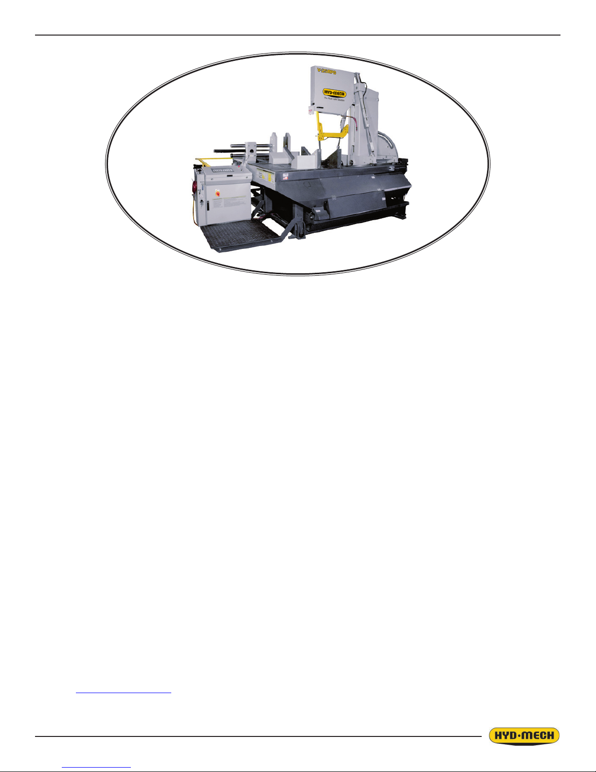
V-25APC
2007
859331
Thank you,
On behalf of everyone at HYD·MECH Group Limited, we would like to thank and congratulate you on your decision to
purchase a HYD·MECH bandsaw.
Your new machine is now ready to play a key role in increasing the efciency of your operation, helping you to reduce
cost while boosting quality and productivity.
To ensure you are maximizing the power and versatility of your new HYD·MECH bandsaw, please take the time to
familiarize yourself and your employees with the correct operation and maintenance procedures as outlined in this
manual.
We sincerely appreciate the condence you have demonstrated in purchasing our product and look forward to building
a long and mutually benecial relationship.
Thank you
Hyd·Mech Group Limited
P.O. Box 1659, 1079 Parkinson Road
Woodstock, Ontario, N4S 0A9
Phone : (519) 539-6341
Service : 1-877-237-0914
Sales : 1-877-276-SAWS (7297)
Fax : (519) 539-5126
e-mail : info@hydmech.com
Printed June, 2010
1


TABLE OF CONTENTS
SECTION 0 - SAFETY INSTRUCTIONS
SUMMARY .......................................................................................................................................0.1
BASIC RULES ..................................................................................................................................0.3
SAFETY HAZARD LABELS .............................................................................................................0.6
LOCATION AND PART NUMBERS OF SAFETY HAZARD LABELS ON V-25APC ........................0.8
SECTION 1 - INSTALLATION
SAFETY CONSIDERATIONS ..........................................................................................................1.1
V-25 APC LIFTING AND SHIPPING.................................................................................................1.2
LEVELING THE V-25 APC ...............................................................................................................1.3
BARFEED INSTALLATION ..............................................................................................................1.4
CONVEYOR INSTALLATION (OPTIONAL) ....................................................................................1.12
OUTFEED CONVEYOR ..................................................................................................................1.12
INFEED CONVEYOR ......................................................................................................................1.12
POWERED CONVEYORS (REFER TO ELECTRICAL SCHEMATICS) .........................................1.12
CUTTING FLUID .............................................................................................................................1.13
HYDRAULIC OIL .............................................................................................................................1.13
WIRING CONNECTIONS ................................................................................................................1.13
BLADE TENSION CHECK ..............................................................................................................1.13
EARTH GROUNDING PROCEDURE .............................................................................................1.14
SECTION 2 - OPERATING INSTRUCTIONS
E300 INTERFACE OPERATION INSTRUCTIONS ..........................................................................2.1
MANUAL MODE ONLY CONTROLS ...............................................................................................2.2
MANUAL & AUTO MODE CONTROLS ............................................................................................2.2
MACHINE & CYCLE CONTROLS ....................................................................................................2.3
OPTIONAL EQUIPMENT CONTROLS ............................................................................................2.4
MANUAL MODE ...............................................................................................................................2.5
COLLISION DETECTION FEATURE ...............................................................................................2.6
PARAMETERS .................................................................................................................................2.7
OPENING THE FRONT GATE IN MANUAL AND AUTOMATIC MODE ...........................................2.9
ONE CUT MODE OPERATION .......................................................................................................2.10
AUTOMATIC OPERATION ..............................................................................................................2.10
SEQUENCE OF OPERATION ........................................................................................................2.12
MECHANICAL CONTROLS ............................................................................................................2.13
HEAD FORWARD LIMIT SETTING ................................................................................................2.13
HEAD BACK LIMIT SETTING .........................................................................................................2.13
OUT OF STOCK COLLAR ..............................................................................................................2.14
COOLANT FLOW ............................................................................................................................2.14
PRIMING THE COOLANT PUMP ...................................................................................................2.14
RESTRICTIONS - HEAD SWING LEFT ..........................................................................................2.14
i

SECTION 3 - MAINTENANCE & TROUBLE SHOOTING
SAFETY DURING MAINTENANCE AND TROUBLESHOOTING ....................................................3.1
LOCK-OUT PROCEDURE ...............................................................................................................3.1
BLADE CHANGE PROCEDURE .....................................................................................................3.2
BLADE INSTALLATION ....................................................................................................................3.4
BLADE TRACKING ..........................................................................................................................3.5
DRIVE WHEEL ADJUSTMENT ........................................................................................................3.6
IDLER WHEEL ADJUSTMENT ........................................................................................................3.6
BLADE GUIDES ...............................................................................................................................3.7
BLADE BRUSH ADJUSTMENT .......................................................................................................3.8
BLADE WIPERS...............................................................................................................................3.8
LUBRICATION ..................................................................................................................................3.9
OUTPUT SHAFT LUBRICATION ....................................................................................................3.10
GEARBOX LUBRICATION (V-25APC WITH A503 GEARBOX) .....................................................3.10
HYDRAULIC MAINTENANCE .........................................................................................................3.11
TROUBLE SHOOTING GUIDE .......................................................................................................3.12
SECTION 4 - ELECTRICAL
FOR ELECTRICAL SCHEMATICS AND COMP. PARTS LISTS SEE PDF ON ATTACHED CD .....4.1
SECTION 5 - HYDRAULICS
FOR HYDRAULIC SCHEMATICS AND PLUMBING DIAGRAMS SEE PDF ON ATTACHED CD ...5.1
V-25APC HYDRAULIC PARTS LIST ................................................................................................5.1
GLAND & PISTON ASSEMBLIES ....................................................................................................5.2
SECTION 6 - MECHANICAL ASSEMBLIES
FOR MECHANICAL ASSEMBLY DRAWINGS SEE PDF ON ATTACHED CD ................................6.1
SECTION 7 - OPTIONS
MIST COOLANT OPTION ................................................................................................................7.1
VARIABLE VISE PRESSURE OPTION ...........................................................................................7.1
FOR OPTIONAL DRAWINGS AND PARTS LIST SEE PDF ON ATTACHED CD ............................7.1
BUNDLING OPTION ........................................................................................................................7.2
SETTING THE HEIGHT OF THE INFEED AND OUTFEED VISE BUNDLING IN AUTO MODE ....7.2
BUNDLING HEIGHT RESTRICTIONS .............................................................................................7.2
SHUTTLE BUNDLING ......................................................................................................................7.2
SAW BUNDLING (INFEED VISE AND OUTFEED VISE) ................................................................7.4
SECTION 8 - SPECIFICATIONS
V-25APC BANDSAW SPECIFICATIONS .........................................................................................8.1
V-25APC 5’ BARFEED LAYOUT .....................................................................................................8.2
V-25APC 10’ BARFEED LAYOUT ...................................................................................................8.4
WARRANTY .....................................................................................................................................9.1
SECTION 9 - WARRANTY
ii

SECTION 0 - SAFETY INSTRUCTIONS
SUMMARY
All persons operating this machine must have read and understood all of the following sections of this Manual:
Section 0 SAFETY
Section 2 OPERATING INSTRUCTIONS
However, as a memory aid, the following is a summary of the Safety Section.
Put Safety First
Mandatory Information – What operators and maintenance people must have read and understood.
Signatures – Everyone involved with this machine must sign to conrm they have read and understood mandatory infor-
mation.
Basic Rules – only use this machine when
• It is in good working order.
• All safety equipment is in place and functional.
• Operations are in compliance with this manual.
• Materials are within designed specications and are non-hazardous.
Owner is responsible to
• Keep Manual accessible at the machine.
• Ensure only reliable, fully trained personnel work with the machine.
• Clearly dene responsibilities of all personnel working with the machine.
• Keep the machine in good working order.
Operator and Maintenance Personnel are responsible to:
• Keep all safety equipment in order, check its function at the beginning of each shift, and report any shortcomings.
• Shut down machine and report any faults or malfunctions that could impair safety.
• Understand and obey safety hazard labels.
• Not to wear un-restrained long hair, loose clothing or jewellery.
• Wear all required personal protective equipment.
• Not to wear gloves within 24 inches of moving blade.
• Maintain a clean working area and machine.
• Always use Lock-out when performing maintenance or repairs.
0.1

FOREWORD
Put Safety First!
This Safety Section contains important information to help you work safely with your machine and describes the dangers
inherent to bandsaws. Some of these dangers are obvious, while others are less evident.
It really is important to PUT SAFETY FIRST. Make it a habit to consider the hazards associated with any action BEFORE
you do it. If you feel any uncertainty, stop and nd a safer approach to the action. If you’re still uncertain, ask for advice
from your supervisor.
The SAFETY FIRST approach is particularly necessary when you do something new, or different, and most people instinctively recognize this, although impatience may still cause them to take unnecessary risks.
Danger also lurks in the routine task that we have done over and over. Here, familiarity, boredom, or tiredness may lull us
into unthinking, automatic repetition. Be alert for this, and when you feel it happening, stop and take stock of your
situation. Review the safety hazards associated with what you are doing. That should get your brain working again.
Certainly production is important, but if you think you’re too busy to put safety rst, think how much production you’ll lose if
you get hurt.
You owe it to yourself, your family, and your co-workers to PUT SAFETY FIRST.
Mandatory Information
All persons operating this machine must have read and understood all of the following sections of this Manual:
Section 0 SAFETY
Section 2 OPERATING INSTRUCTIONS
Personnel involved in installation and maintenance of the machine must have read and understood all sections of the
manual
Persons who have difculty reading, or for whom English is not their rst language, must receive particularly thorough
instruction.
Signatures
Everyone involved in operation of this machine must sign below to conrm that:
I have read and understood all parts of Section 0 – Safety, and Section 2 – Operating Instructions.
Name Date Signature
Everyone involved in the installation, inspection, maintenance, and repair of this machine must sign below to conrm that:
I have read and understood all parts of this Operation and Maintenance Manual.
Name Date Signature
0.2

BASIC RULES
Intended Use
Exclusion of Misuse
Liability
Our machines are designed and built in line with the state of the art, and specically in accordance with
American National Standards Institute Standard B11.10 Safety Requirements for Metal Sawing Machines.
However, all machines may endanger the safety of their users and/or third parties, and be damaged,
or damage other property, if they are operated incorrectly, used beyond their specied capacity, or for
purposes other than those specied in this Manual.
Misuse includes, for example:
Sawing hazardous materials such as magnesium or lead.
Sawing work pieces which exceed the maximum workload appearing in the Specications.
Operating the machine without all original safety equipment and guards.
The machine may only be operated:
When it is in good working order, and
When the operator has read and understood the Safety and Operating Instructions Sections of the
Manual, and
When all operations and procedures are in compliance with this Manual.
Hyd-Mech Group cannot accept any liability for personal injury or property damage due to operator errors
or non-compliance with the Safety and Operating Instructions contained in this Manual.
RESPONSIBILITIES OF THE OWNER
Organization of work
This Operation and Maintenance Manual must always be kept near the machine so that it is accessible to
all concerned.
The general, statutory and other legal regulations on accident prevention and environmental protection
must also be observed, in addition to the Manual material. The operators and maintenance personnel
must be instructed accordingly. This obligation also includes the handling of dangerous substances and
the provision and use of personal protective equipment.
Choice and qualication of personnel
Ensure that work on the machine is only carried out by reliable persons who have been appropriately
trained for such work.
Training
Everyone working on or with the machine must be duly trained with regard to the correct use of the
machine, the correct use of safety equipment, the foreseeable dangers that may arise during operation of
the machine, and the safety precautions to be taken.
In addition, the personnel must be instructed to check all safety devices at regular intervals.
0.3

Dene responsibilities
Clearly dene exactly who is responsible for operating, setting-up, servicing and repairing the machine.
Dene the responsibilities of the machine operator and authorize him to refuse any instructions by third
parties if they run contrary to the machine’s safety.
Persons being trained on the machine may only work on or with the machine under the constant
supervision of an experienced operator. Observe the minimum age limits required by law.
Condition of Machine and Workplace
Ensure that the machine and its safety equipment are kept in good working order.
Ensure that the work area is well lit, and protected from the elements, such as rain, snow, abrasive dust,
and extremes of temperature.
Ensure that the machine is installed with sufcient clearance around it for the safe loading and unloading
of work pieces.
RESPONSIBILITIES OF THE OPERATOR AND MAINTENANCE PERSONNEL
Safety equipment
All machines are delivered with safety equipment that must not be removed or bypassed during operation.
The correct functioning of safety equipment on the machine must be checked:
• At the start of every shift.
• After maintenance and repair work
• When starting for the rst time, and after prolonged shutdowns
Emergency Stop Button (E-Stops)
Always be aware of the location of the Emergency Stop Button(s). Do not allow material or objects to
block your access to an Emergency Stop.
Damage
If any changes capable of impairing safety are observed in the machine or its operation, such as damage,
malfunctions, or irregularities, then appropriate steps must be taken immediately, the machine switched
off, locked-out, and the fault reported to the responsible person.
Safe operation
The machine may only be operated when in good working order and when all protective equipment is in
place and operational.
Keep a safe distance from all moving parts – especially the blade and vises.
Stock should not be loaded onto the saw if the blade is running.
Long and heavy stock should always be properly supported in front of and behind the saw.
Faults
The machine must be switched off and locked-out before starting to remedy any faults.
Safety hazard labels
Safety hazard labels and other instructional labels on the machine must be observed. They must be
clearly visible and legible at all times. If they become damaged they must be replaced.
0.4

Clothing, jewellery, protective equipment
Personnel operating or working on the machine must not wear un-restrained long hair, loose-tting
clothes and dangling jewellery.
When operating or working on the machine, always wear suitable, ofcially tested personal protective
equipment such as safety glasses and safety boots and any other equipment required by plant
regulations.
Gloves
Experience has shown that careless use of gloves around machinery is a major factor in serious hand
injuries.
Gloves should not be worn when operating or adjusting the machine, except:
Wear protective gloves when handling bandsaw blades at blade changes.
Gloves may be worn when handling work pieces, only if the machine is in Manual Mode and the
bandsaw blade is not running.
If the machine is running in Auto Mode, and only if the cut parts are greater than 24 inches
long, it may be possible to safely wear gloves for handling the cut parts, but the wearer of the
gloves must never put his hands near the blade for any reason. If the cut parts are less than 24
inches long, it is required to arrange their automatic ow into a parts bucket or other suitable
arrangement to avoid the necessity to pick them off the machine by hand.
Hearing protection
Ear protection must be worn whenever necessary.
The level and duration of noise emission requiring hearing protection depends upon the national regulations in the country in which the machine is being used.
The actual level of noise emission by band sawing machines depends upon work piece size, shape and
material, blade type, blade speed and feed rate.
The only practical course of action is to measure the actual noise emission levels for the type of work that
is typically done. With reference to national standards, decide upon the necessary hearing protection
required.
In the absence of such measurements, it is advisable for anyone exposed to long periods of moderate to
loud noise to wear hearing protection. It is important to understand that hearing loss is gradual and easily
goes un-noticed until it is serious and irreversible.
Workplace
A clear working area without any obstructions is essential for safe operation of the machine. The oor
must be level and clean, without any build-up of chips, off-cuts, coolant, or hydraulic oil.
The workplace must be well lit, and protected from the elements, such as rain, snow, abrasive dust, and
extremes of temperature
Nothing may ever be placed on, or leaned against the machine, with the obvious exception of the work
piece on the table and conveyor of the machine.
0.5

Master Disconnect
Lock-out the machine before undertaking any maintenance or repair work on it. ‘Lock-out’ refers switching
off the master electrical disconnect switch, and locking it out so that it cannot be switched on again
without authorization.
On Hyd-Mech machines the Master Disconnect Switch will be of one of three types:
• Rotary switch mounted in electrical control cabinet door and inter-locked with door.
• Lever switch mounted in separate box mounted on the machine.
• Supply disconnect switch supplied by user at installation and usually wall-mounted within sight of
the machine, depending upon local regulations.
In almost all jurisdictions, it is required that owners of industrial equipment establish and post
lock-out procedures. Know and use the lock-out procedures of your company or organization.
Residual Risks
The machine is still not completely de-energized if an electrical cabinet door type switch is
locked-out.
The line side of the disconnect switch itself remains energized.
Variable speed blade drives store dangerous voltage in their capacitors, and this requires time to
dissipate. After locking out power, wait 3 minutes before beginning to work on machine electrical
circuits.
If compressed air is supplied to the machine to power a mist lubrication system or other devices,
it should be disconnected, and any stored air pressure released before working on the machine.
The weight of individual machine components represents stored potential energy that can be
released if they fall when disconnected. Secure these components with adequate hoisting gear
before disassembly.
SAFETY HAZARD LABELS
The safety hazard labels attached to your machine represent important safety information to help you avoid personal injury
or death.
All supervisors, operators, and maintenance personnel must locate and understand the safety information associated with
each hazard label prior to operating or servicing the machine.
The safety hazard labels shown below are located at various positions on the machine to indicate possible safety hazards.
The location and re-order part number of all the safety labels associated with this particular model of bandsaw are indicated
at the end of this section of the manual. It is important to replace any safety hazard label that becomes damaged or
illegible.
HAZARDOUS VOLTAGE INSIDE
Contact with high voltage may cause death or serious injury. Never perform
maintenance on, or near, electrical components until the machine’s electrical power
source has been disconnected. Lock-out power in accordance with your company’s
lock-out procedures before any such maintenance. The “Stop” or “Emergency Stop”
push button does not disconnect the machine’s power supply. Hazardous voltage
is still present in the machines electrical circuits.
The machine’s Electrical Disconnect Switch does disconnect voltage from the
machine’s circuits; however hazardous voltage is still present inside the main
electrical cabinet, on the infeed (line) side of the main fuses. Therefore keep hands and tools away from the infeed side of
the control panel main fuses. If these fuses need to be replaced, use a fuse puller.
Allow three minutes after locking-out power before opening any electrical enclosures. Your machine may be equipped with a
variable frequency drive that stores high voltage within its capacitors. Three minutes will allow sufcient time for this voltage
to safely discharge.
Never spray coolant directly at electrical components or cabinets.
0.6
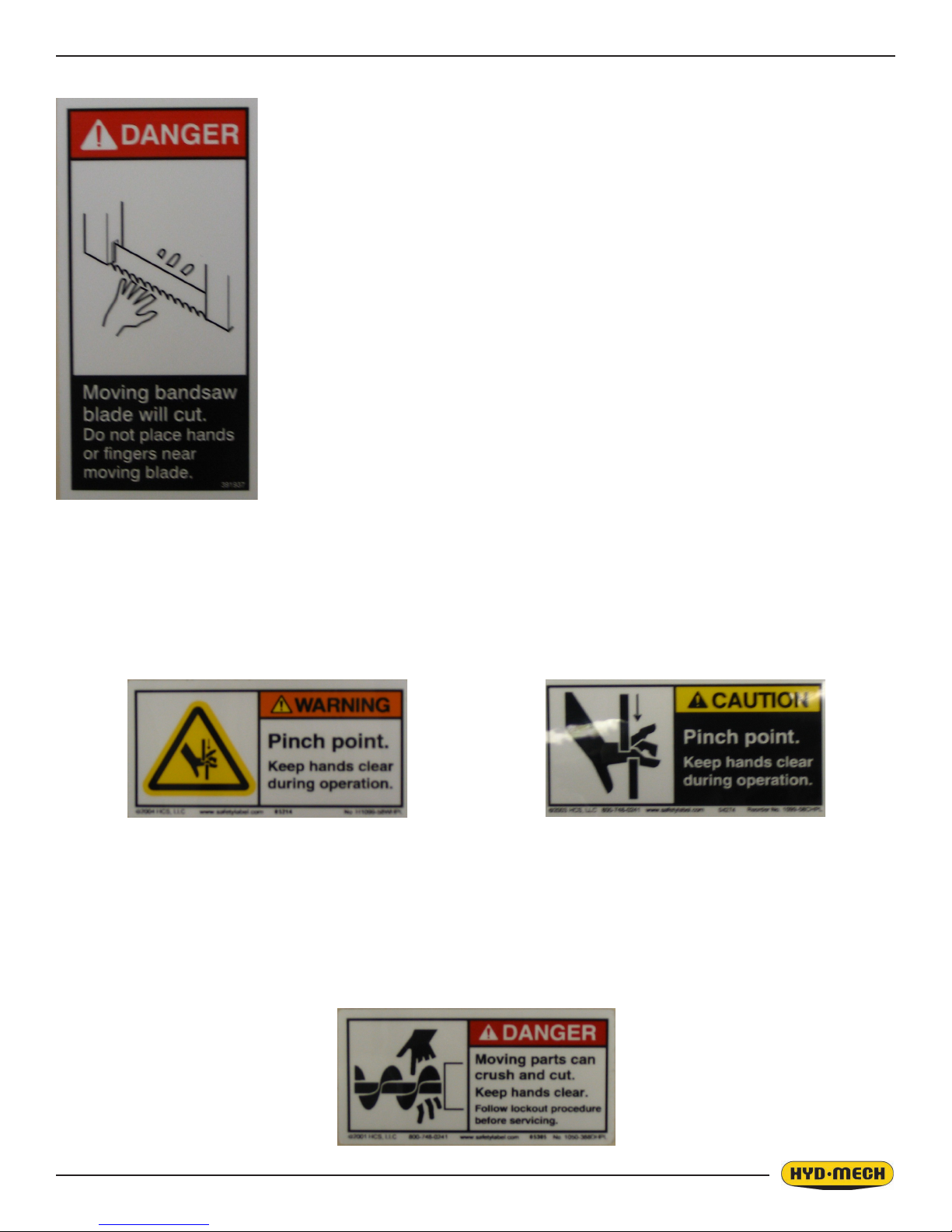
PINCH POINT
MOVING BANDSAW BLADE WILL CUT
Do NOT operate with guard removed.
Do NOT place hands or ngers near moving bandsaw blade.
For blade changing, always follow the proper Blade Changing Procedure, as given in
Section 3 of this manual.
Machine parts may move without warning, either because the machine is operating automatically, or because another
person initiates the motion. Keep hands clear of all labelled pinch points, whenever the machine is running. Machine vises
can exert great force and cause severe injury. Keep hands clear of vises and work piece when vises are opened or closed.
Be aware that vise closing or opening may result in potentially dangerous work piece movement. Be aware also that the
opening motion of a vise may create potential pinch points.
MOVING PARTS CAN CRUSH AND CUT
Keep hands clear of chip auger. Lock-out power in accordance with your company’s lock-out procedures before attempting
to clear a jam in the chip auger.
Be aware that the chip auger may start unexpectedly, either because the machine is operating automatically, or because
another person initiates the motion.
If the chip auger is stalled because of a jam, it may start without warning when the jam is cleared, unless the machine power
is locked out.
0.7
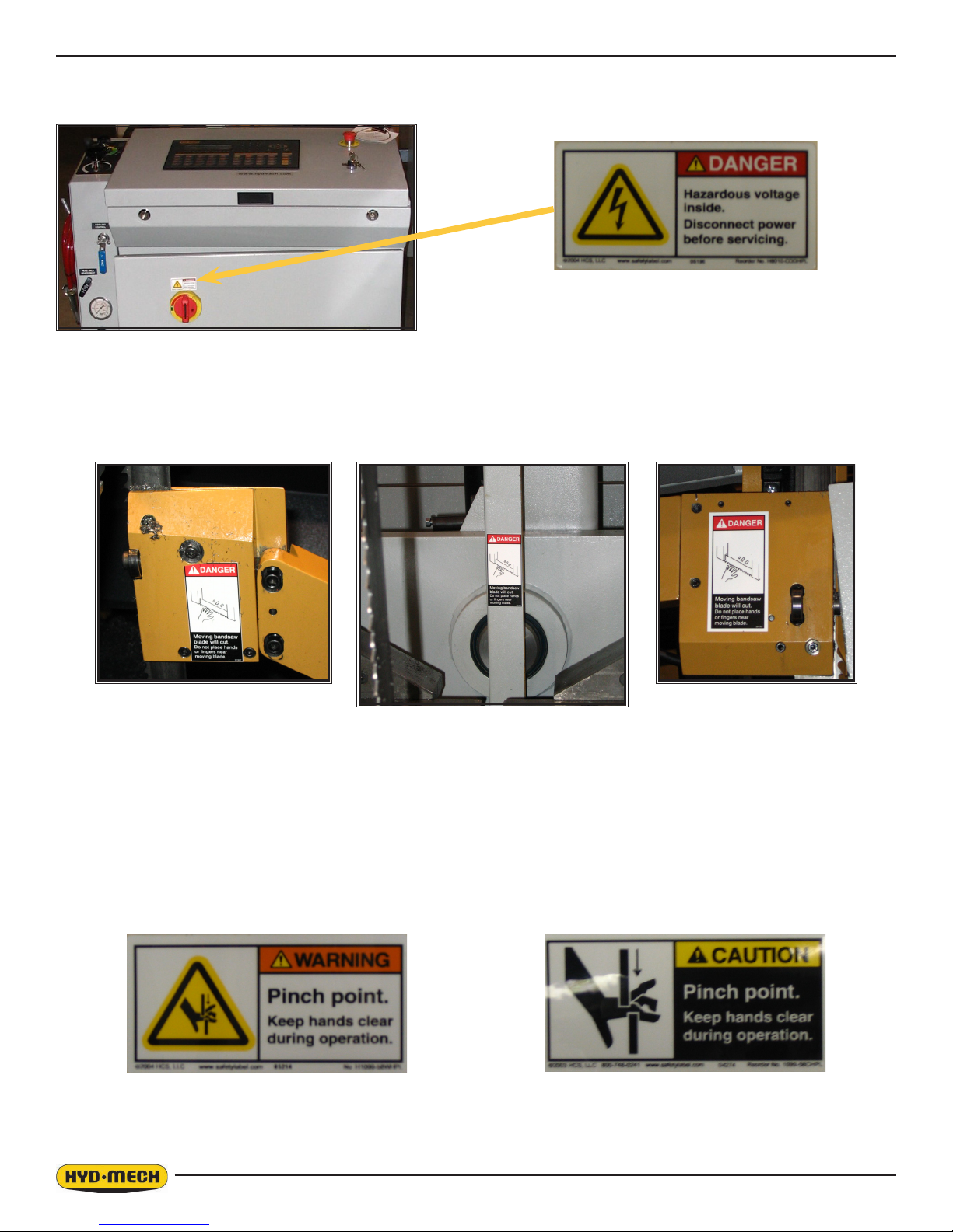
LOCATION AND PART NUMBERS OF SAFETY HAZARD LABELS ON V-25APC
DANGER
Hazardous voltage inside
Item N0. 391938
DANGER
Moving bandsaw blade will cut
Item N0. 391937
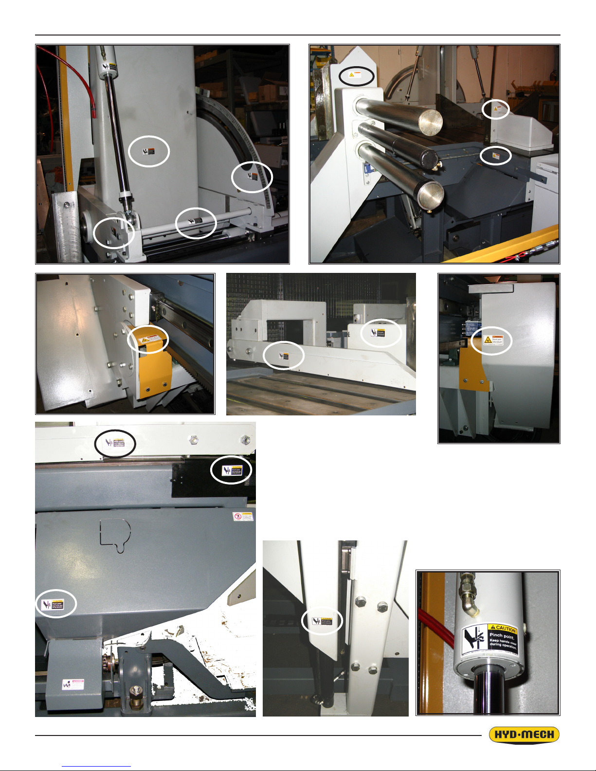
The following pictures on the next page show the locaton of label: WARNING Pinch Point
WARNING
Pinch Point
Item N0. 392801
0.8
0.9
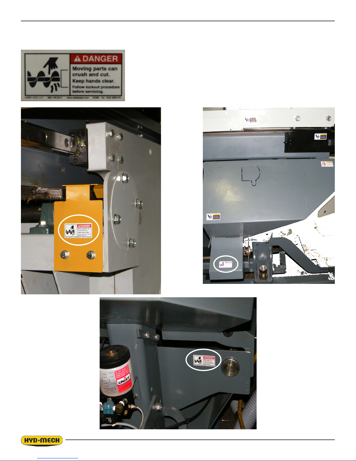
The following pictures show the locaton of label: DANGER. Moving parts can crush and cut. Keep hands clear.
DANGER
Moving parts can crush and cut. Keep hands clear.
Item N0. 391335
0.10
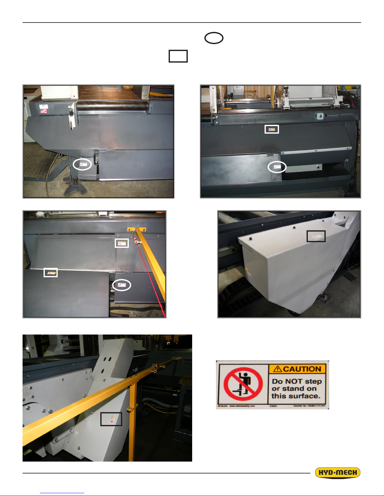
The following pictures show the locaton of labels :
1. DANGER. Moving parts can crush and cut. Keep hands clear.
2. CAUTION. Do NOT step or stand on this surface.
CAUTION
Do NOT step or stand on this surface.
Item N0. 391632
0.11

0.12

SECTION 1 - INSTALLATION
SAFETY CONSIDERATIONS
All safety precautions must be observed during installation, operation, or repair work on the V-25 APC bandsaw machine.
Inspect the machine thoroughly before power hook-up. Pay special attention to the electrical and hydraulic systems to
ensure no damage was caused in shipping.
Power hook-up must be performed by qualied personnel.
If not performing properly, the machine should be stopped immediately and set-up, or repaired by a qualied person.
Stock must not be loaded while the blade is running and the V-25 APC should not be operated unless all guards, covers,
and doors are in place and closed.
Long and heavy stock should be supported where it extends off the saw table.
The operator should keep a safe distance from all moving parts especially the blade and operating vises.
Long hair, loose clothing, or gloves, should not be worn while operating the V-25 APC.
The area around the machine should be kept clean and tidy.
The V-25 APC machine should be used according to its specications.
The operator must wear eye protection.
No modications to the machine are allowed without Hyd-Mech’s prior approval. Any approved modications
shall be performed by trained personnel.
1.1
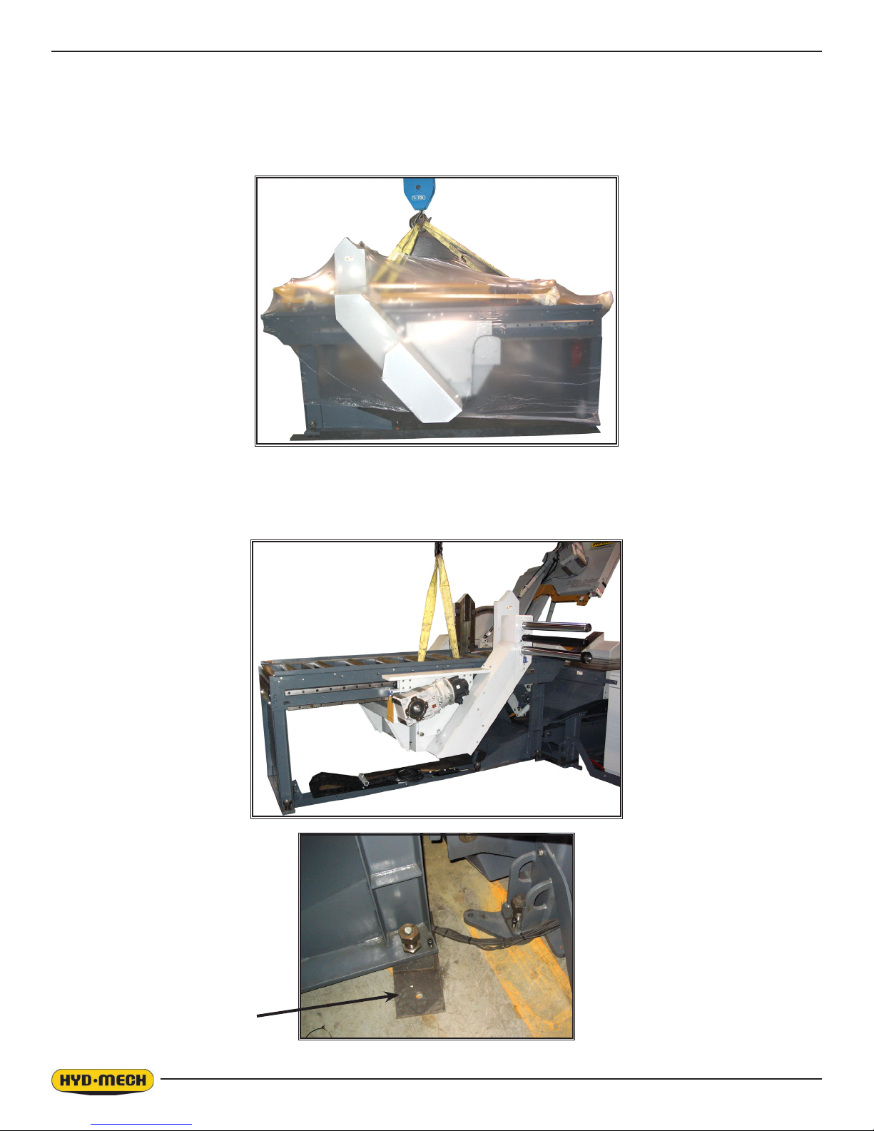
V-25 APC LIFTING AND SHIPPING
The shipping weight of the V-25 APC is 10000 lb. The front-to-rear location of the centre of gravity is midway between
the chain holes on the lifting angles. Side-to side the centre of gravity is about 7” to the right of the centre line of the saw
table. With the left hand barfeed, the centre of gravity will be about 5” forward and 5” to the left of the normal position.
CRANE
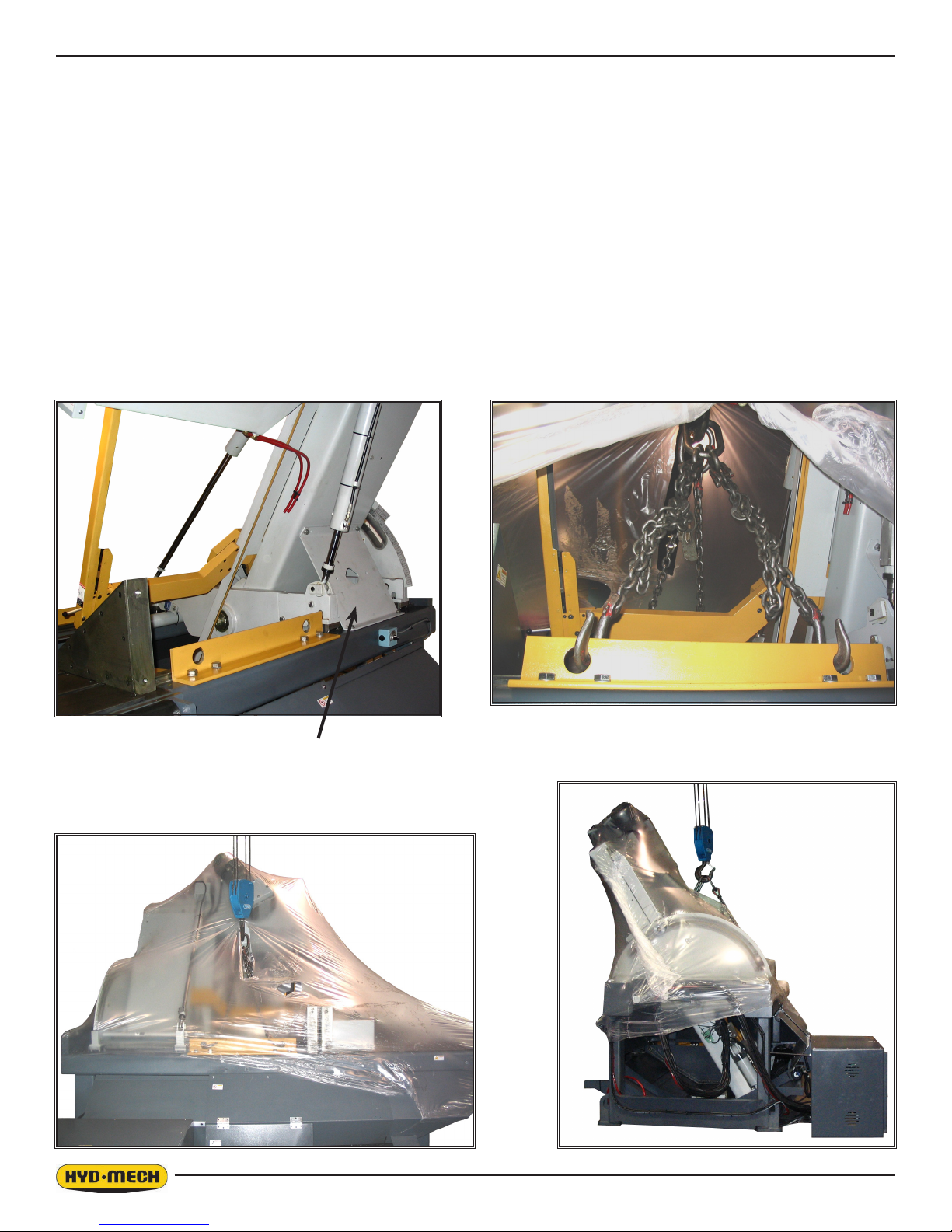
Before lifting with a crane, the head must be retracted, swung to 64° right, and locked in position using the supplied head
restraint plate and four ½ NC bolts. The upper guide arm must be fully lowered.
Four chains should be connected to the four holes in the lifting angles which bolt to the table rails as shown in the illustrations. Chain lengths must be carefully adjusted so that the crane is above the centre of gravity, and the chains, when
tightened, do not contact any part of the head or guide arm.
NOTE: The head restraint plate and two lifting angles must be removed before machine start up.
Head Restraint Plate
Lifting Angles (x2)
1.2
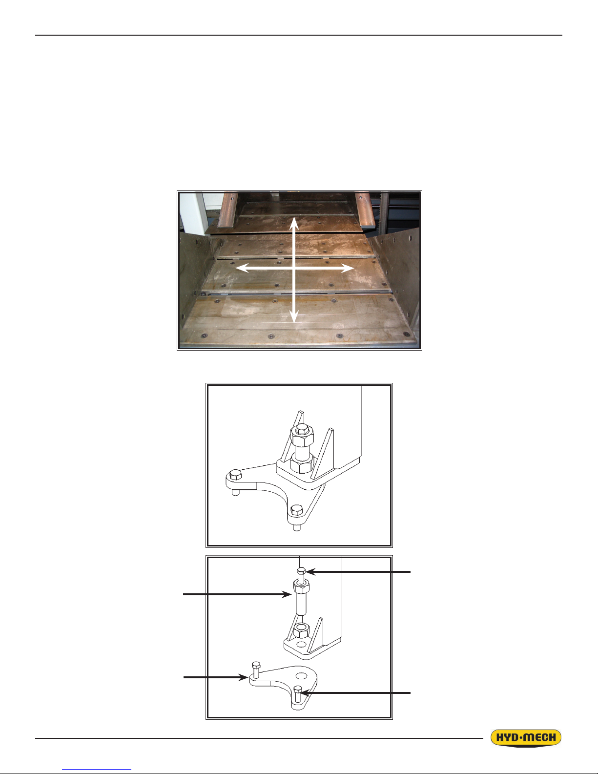
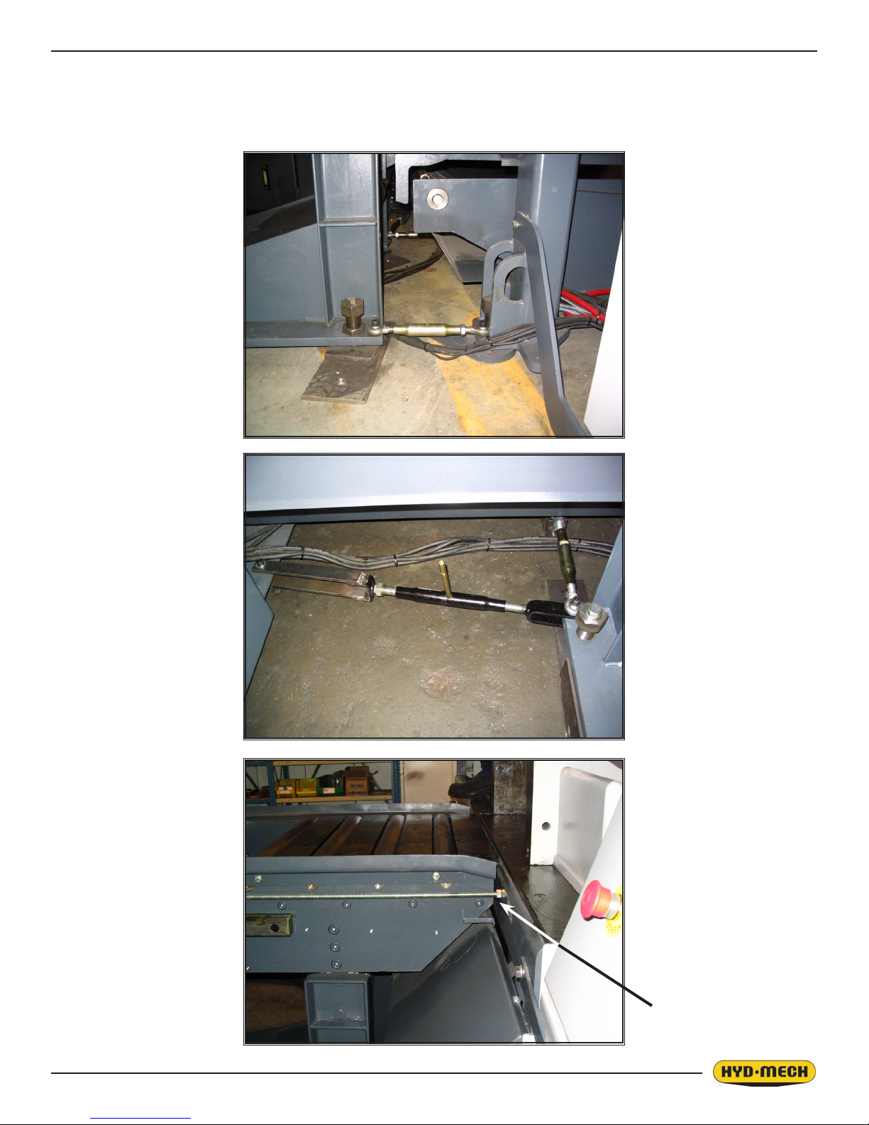
LEVELING THE V-25 APC
It is important that the V-25 APC sit solidly on all four leveling bolts, and that the saw table be level. The V-25 APC is
stable in all head positions, and it is not necessary to bolt the saw directly to the oor. The leveling plates provided have
a dimple for the leveling bolt to sit in, and two holes for lagging the plate to the oor. As long as at least two plates are
lagged with two bolts each, the saw will be positively located. The advantage of this approach is that an accidental collision with the saw may pop the saw out of the dimples, but damage to the saw and the lagging is minimized.
Leveling is checked by applying an accurate bubble level to the saw table, checking level both front-to-rear and side-toside. Lock the level using the jam nuts on the leveling bolts.
At least two of the leveling feet should be anchored to the oor.
Leveling Bolt
Optional - for direct anchoring
Leveling Plate
Anchor bolts
1.3
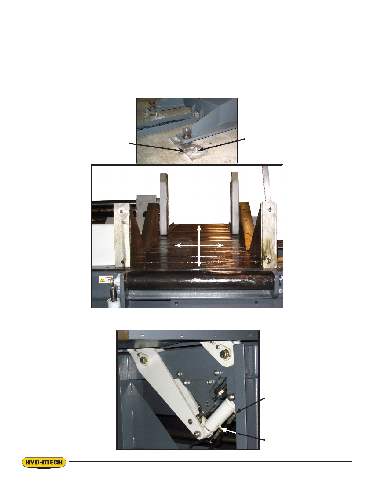
BARFEED INSTALLATION
1. The shipping weight of the barfeed is 5000 lb. Place one lifting sling around the front horizontal cross member located
28” back from the front of the conveyor. Place another sling around the cross member located 15” forward of the rear of
the conveyor. The slings should be about 2” to the right of the centre line of the conveyor (towards the movable jaw side).
Lift the barfeed and slide it into position towards the machine.
2. Place the 6 levelling plates for the barfeed under each of the levelling bolts, then lower the barfeed to the ground in line
with the machine. Remove the cable trough, cable track, and the associated hoses and cords from the machine coolant
tray. Place the cable trough into position under the barfeed. Slide the cable track and bundle of hoses/cords under the
front end of the barfeed and into the cable track.
Levelling Plate
1.4
3. Connect the three lower struts that assemble the front leg of the barfeed to the saw. The nished gap between the front
plate of the conveyor and the rear plate of the machine is to be 5/8” +/- 1/8”. The alignment between the barfeed and
machine should be checked quickly with a 10’ piece of cold rolled at bar or a laser. Adjust the struts if necessary.
GAP
⅝” +/- ⅛”
1.5
4. The six levelling plates should be lagged to the concrete oor with ¾” x 4¾” heavy duty concrete wedge anchors and
strong tack welds should be placed at all six areas.
As mentioned earlier, the conveyor should be leveled in both directions; across and along the infeed conveyor. Six leveling screws are provided, three down each length of the conveyor.
Leveling is checked by applying an accurate bubble level to the saw table, checking level both front-to-rear and side-toside. Lock the level using the jam nuts on the leveling bolts.
NOTE: Leveling the infeed conveyor with a slight slope towards the blade will prevent coolant from running down the raw
stock.
Tack Weld
Anchor
5. At the barfeed front leg, connect hose 151 to the cap port of the shuttle lift cylinder and hose 152 to the gland port.
151
152
1.6
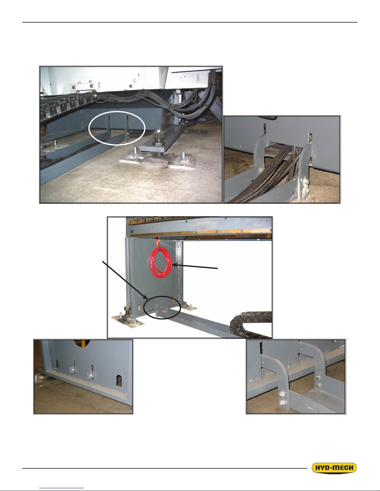
6. The cable trough is located by four L-shaped brackets; two hooked into each front and rear conveyor legs. Fasten two
of the brackets to the front end of the cable trough and then place them into the slots at the front conveyor leg. Slide the
other two brackets through the slots of the rear leg and fasten them to the cable trough. Install the two capture bolts to the
brackets on the outside of the rear leg.
Capture bolts for the
bracket are on the back
side of the rear leg.
Coolant drain line
7. The barfeed coolant drain line is tied to the rear leg. Cut and route through the cable trough into the chip tray of the
saw. Be careful to not interfere with the travel of the chip paddle.
1.7
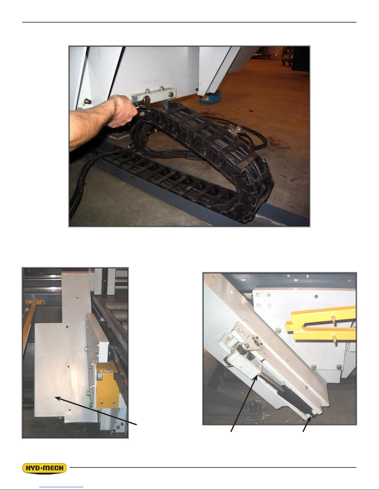
8. Fasten the cable track upper bracket to the back of the carriage box centre.
9. Remove the datum vise toggle cover - three 3/8 NC bolts on top, and two 3/8 NC bolts on the underside. Install the rod
end of the cylinder with the 1/2 NF x 1.50 socket bolt. Fasten the lower cylinder eye with the 1/2 NC x 4.50 hex bolt. Zip
tie the cylinder hoses (141 and 142) to the bottom of the carriage box centre. Re-install the datum vise toggle cover.
Cover
Rod end Lower cylinder eye
1.8
 Loading...