

Hyd-Mech V-18 APC User Manual
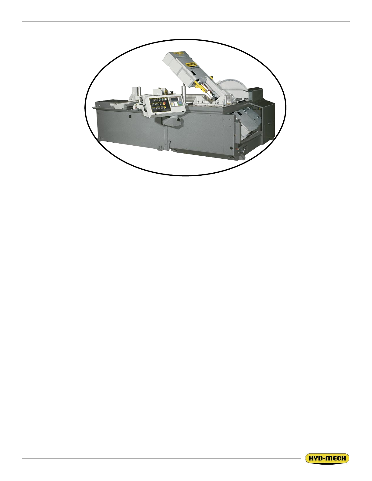
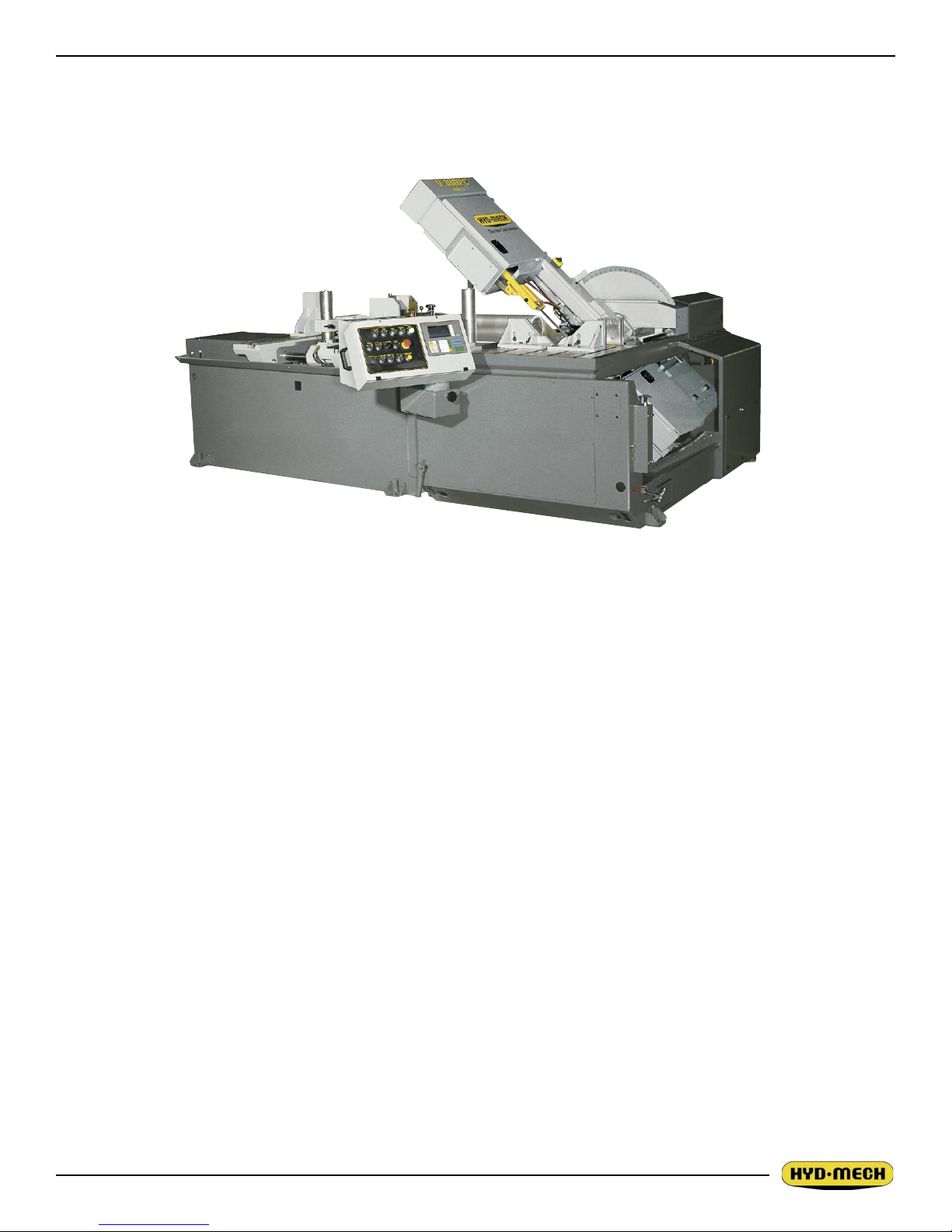
V-18 APC
August, 2004 Revision C
393440
THANK YOU,
On behalf of everyone at HYD.MECH, I would like to thank and congratulate you on your decision to purchase
a HYD.MECH band saw.
Your new machine is now ready to play a key role in increasing the efciency of your operation, helping you to
reduce cutting costs while boosting quality and productivity.
To ensure you are maximizing the power and versatility of your new HYD.MECH band saw, please take the
time to familiarize yourself and your employees with the correct operation and maintenance procedures as
outlined in this manual.
We sincerely appreciate the condence you have demonstrated in purchasing our product and look forward to
building a long and mutually benecial relationship.
Thank-you.
HYD.MECH GROUP LIMITED
P.O. BOX 1030, 1079 Parkinson Road
Woodstock, Ontario Canada, N4S 8A4
Phone: (519) 539-6341
Service 1-877-237-0914
Sales 1-877-276-SAWS(7297)
Fax (519) 539-5126
e-mail, info@hydmech.com
01


TABLE OF CONTENTS
SECTION 1, INSTALLATION
SAFETY PRECAUTIONS........................................................................................................................... 1.1
LIFTING AND SHIPPING........................................................................................................................... 1.2
REMOVING HEAD RESTRAINTS ............................................................................................................. 1.2
HYDRAULIC DOOR RESTRAINT.............................................................................................................. 1.2
INSTALLATION OF THE CONTROL PANEL ............................................................................................. 1.2
LEVELLING THE V-18 ............................................................................................................................... 1.3
HYDRAULIC OIL........................................................................................................................................ 1.3
CUTTING FLUID ........................................................................................................................................ 1.3
WIRING CONNECTIONS........................................................................................................................... 1.4
BLADE TENSION CHECK ......................................................................................................................... 1.4
EARTH GROUNDING PROCEDURE........................................................................................................ 1.4
SECTION 2, OPERATING INSTRUCTIONS
START-UP.................................................................................................................................................. 2.1
OPERATOR PANEL SWITCHES ............................................................................................................... 2.2
OPERATION OVERVIEW .......................................................................................................................... 2.4
PLC CONTROL DESCRIPTION ................................................................................................................ 2.4
ACTIVATING THE PLC .............................................................................................................................. 2.4
FUNCTION BUTTON DESCRIPTION........................................................................................................ 2.5
SINGLE PART CYCLE OPERATION ......................................................................................................... 2.6
AUTOMATIC OPERATION......................................................................................................................... 2.7
PROCEDURE FOR EDITING OR STARTING A NEW JOB IN AUTO MODE............................................ 2.7
WORKING WITH A QUEUE....................................................................................................................... 2.9
BLADE BASICS ......................................................................................................................................... 2.9
VARIABLE SPEED CONTROL .................................................................................................................. 2.10
HYDRAULIC FEED CONTROL.................................................................................................................. 2.10
CUTTING PARAMETERS CHART............................................................................................................. 2.10
CUTTING SOLIDS ..................................................................................................................................... 2.11
CUTTING STRUCTURALS........................................................................................................................ 2.11
ADDITIONAL CUTTING SETUP EXAMPLES............................................................................................ 2.13
COOLANT FLOW....................................................................................................................................... 2.14
HEAD BACK LIMIT ADJUSTMENT............................................................................................................ 2.14
CHIP CONVEYOR ..................................................................................................................................... 2.15
HYDRAULIC CHIP CONVEYOR................................................................................................................ 2.15
SECTION 3, MAINTENANCE AND TROUBLESHOOTING
BLADE CHANGING ................................................................................................................................... 3.1
BLADE TRACKING .................................................................................................................................... 3.2
DRIVE WHEEL ADJUSTMENT.................................................................................................................. 3.2
IDLER WHEEL ADJUSTMENT .................................................................................................................. 3.3
BLADE BRUSH ADJUSTMENT................................................................................................................. 3.3
BLADE GUIDES......................................................................................................................................... 3.3
HEAD FORWARD LIMIT SETTING ........................................................................................................... 3.4
LUBRICATION............................................................................................................................................ 3.4
HYDRAULIC MAINTENANCE.................................................................................................................... 3.5
TROUBLE SHOOTING GUIDE.................................................................................................................. 3.6
MITSUBISHI PLC 500 TROUBLESHOOTING........................................................................................... 3.8
MITSUBISHI PLC 500 PARAMETERS ...................................................................................................... 3.9
LENGTH CALIBRATION ............................................................................................................................ 3.9
TOC.1

TOC.3
HEAD FEED RATE CALIBRATION............................................................................................................ 3.10
ANGLE CALIBRATION............................................................................................................................... 3.10
PARAMETER DEFINITIONS...................................................................................................................... 3.11
PLC 500 TROUBLESHOOTING EXAMPLES............................................................................................ 3.13
SECTION 4, ELECTRICAL SYSTEM
GENERAL INFORMATION......................................................................................................................... 4.1
INITIAL STARTUP...................................................................................................................................... 4.1
V18 APC 208/240 VOLT ELECTRICAL SCHEMATIC, NO OPTIONS ....................................................... 4.6
V18 APC 208/240 VOLT WIRING DIAGRAM, NO OPTIONS.................................................................... 4.10
V18 APC 208/240 VOLT INPUT AND OUTPUTS, NO OPTIONS.............................................................. 4.14
V18 APC 208/240 VOLT ELECTRICAL SCHEMATIC................................................................................ 4.18
V18 APC 208/240 VOLT WIRING DIAGRAM............................................................................................. 4.22
V18 APC 208/240 VOLT INPUT AND OUTPUTS ...................................................................................... 4.26
V18 APC 480/575 VOLT ELECTRICAL SCHEMATIC, NO OPTIONS ....................................................... 4.30
V18 APC 480/575 VOLT ELECTRICAL WIRING DIAGRAM, NO OPTIONS ............................................. 4.34
V18 APC 480/575 VOLT INPUT AND OUTPUT DEVICES, NO OPTIONS................................................ 4.38
V18 APC 480/575 VOLT ELECTRICAL SCHEMATIC................................................................................ 4.42
V18 APC 480/575 VOLT ELECTRICAL WIRING DIAGRAM...................................................................... 4.46
V18 APC 480/575 VOLT INPUT AND OUTPUT DEVICES ........................................................................ 4.50
SECTION 5,HYDRAULIC
HYDRAULIC MANIFOLD ASSEMBLY PARTS LIST.................................................................................. 5.1
V18 APC HYDRAULIC SCHEMATIC ......................................................................................................... 5.3
V18 APC PLUMBING DIAGRAM ............................................................................................................... 5.4
SECTION 6, MECHANICAL
BLADE BRUSH ASSEMBLY ...................................................................................................................... 6.1
GUIDE ARM ASSEMBLY ........................................................................................................................... 6.2
IDLER WHEEL ASSEMBLY ....................................................................................................................... 6.4
ANGLE SCALE ASSEMBLY....................................................................................................................... 6.5
90º STOP ASSEMBLY................................................................................................................................ 6.6
DIGITAL ANGLE ENCODER ASSEMBLY.................................................................................................. 6.7
ANGLE GEAR DRIVE ................................................................................................................................ 6.8
SHUTTLE ASSEMBLY ............................................................................................................................... 6.9
VISE ASSEMBLY ....................................................................................................................................... 6.10
HYDRAULIC PUMP ASSEMBLY .............................................................................................................. 6.11
SQUARING VISE ASSEMBLY ................................................................................................................... 6.12
SHUTTLE VISE ASSEMBLY ..................................................................................................................... 6.14
HYDRAULIC TANK ASSEMBLY ................................................................................................................ 6.16
COOLANT ASSEMBLY .............................................................................................................................. 6.17
DOORS AND COVERS.............................................................................................................................. 6.18
7 1/2 HP DRIVE ASSEMBLY...................................................................................................................... 6.19
CHIP CONVEYOR (SHOWN WITH CRANK AND OPTIONAL HYDRAULIC MOTOR)............................. 6.20
CHIP CONVEYOR ASSEMBLY PARTS LIST ............................................................................................ 6.21
BUNDLING ASSEMBLY............................................................................................................................. 6.22
SECTION 7, OPTIONAL ASSEMBLIES
POP UP ROLLER ASSEMBLY................................................................................................................... 7.1
TABLE INSERTS........................................................................................................................................ 7.2
TALL VISE INSERTS.................................................................................................................................. 7.3
GUIDE ARM ASSEMBLY (FOR EXTENDED HEAD OPTION) .................................................................. 7.4
TOC.2

HEAD BACK ADJUSTMENT ASSEMBLY ................................................................................................. 7.6
BUNDLING ASSEMBLY............................................................................................................................. 7.7
SECTION 8, SPECIFICATIONS
SPECIFICATIONS...................................................................................................................................... 8.1
SECTION 9, WARRANTY
WARRANTY............................................................................................................................................... 9.1
TOC.3

SECTION 1,INSTALLATION
SAFETY PRECAUTIONS
All safety precautions must be observed during installation, operation, or repair work on the V-18APC II bandsaw machine.
Inspect the machine thoroughly before power hook-up. Pay special attention to the electrical and hydraulic
systems to ensure no damage was caused in shipping.
Power hook-up should be performed by qualied personnel.
If not performing properly the machine should be stopped immediately and set-up or repaired by a qualied
person.
Stock must not be loaded while the blade is running and the V-18APC II should not be operated unless all
guards, covers and doors are in place and closed.
Long and heavy stock should be supported where it extends off the saw table.
Operator should keep a safe distance from all moving parts especially the blade and operating vises.
Long hair, loose clothing or gloves should not be worn while operating the V-18 APC.
The area around the machine should be kept clean and tidy.
The V-18 APC should be used according to its specications.
No modications to the machine are allowed without Hyd·Mech Group Limited’s prior approval. Any
approved modications shall be performed by trained personnel.
1.1
1.3
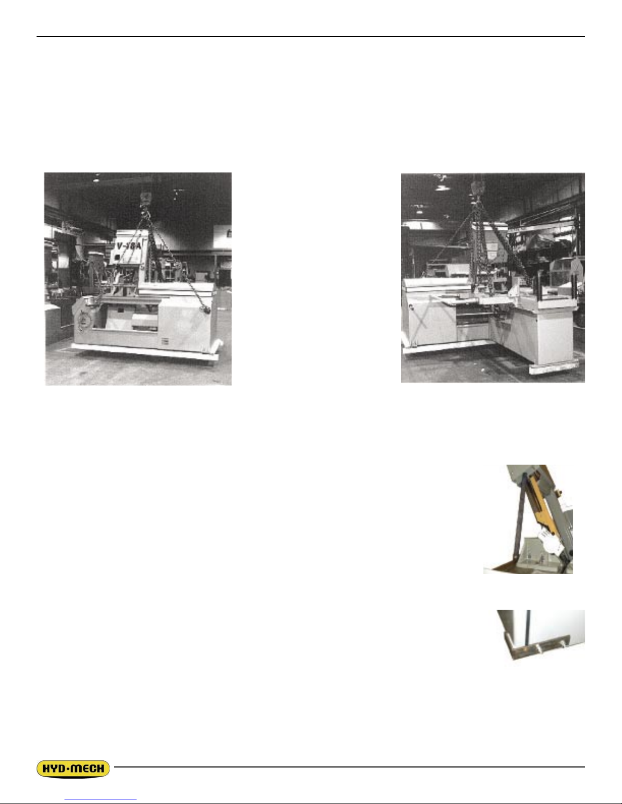
LIFTING AND SHIPPING
To lift a crated V-18APC II bandsaw, a forklift can be used. Minimum capacity of 7500 LB. at 48” from the mast
is required as well as 6’ forks.
To lift the bandsaw with a crane, position the head to 65°. Then insert 2” diameter shafts through the lifting
holes in the machine base.
An experienced rigger should select the rigging based on the 7500 LB. weight of the saw. The photos below
show preferred rigging.
WARNING: Under no circumstances should the lifting chains be pushing against the head.
REMOVING HEAD RESTRAINTS
Before start-up, remove the head support strut installed for shipping purposes to secure
the head to the base. Replace the two 5/16 NC countersunk screws which fasten the
wear-strip down.
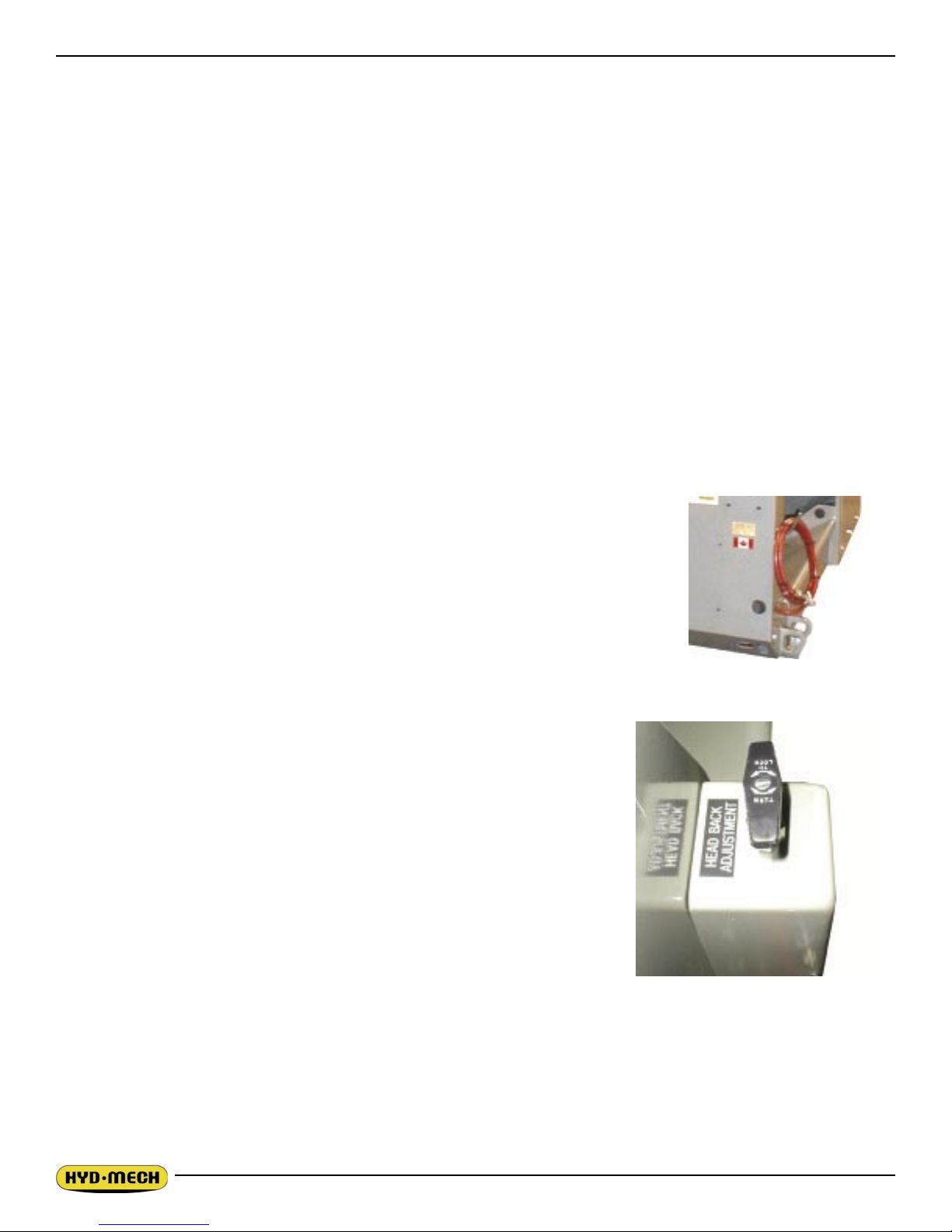
HYDRAULIC DOOR RESTRAINT
There is a restraint bolted to the hydraulic cabinet to keep the door in place during
shipping which must be removed while the machine is raised off the oor. The two bolt
heads can be reached from underneath the cabinet. When the hydraulic door is open,
check for hydraulic leaks that may have developed during shipping.
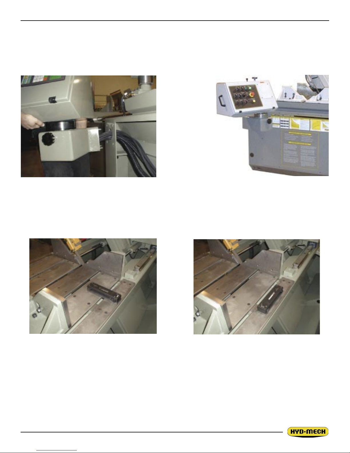
INSTALLATION OF THE CONTROL PANEL
The V18APC II comes equipped an articulating control panel. This panel is normally
removed and placed on the saw table for shipping purposes. The control panel MUST BE
REINSATLLED PRIOR TO MACHINE STARTUP. Take lifting precautions when installing
the panel as it weights 150 LB.
To re-install the panel, follow these steps:
1. Remove all of the packing material.
2. Remove the base front cover from the machine to gain access to the interior of the base.
3. Lift the panel and move it into position as shown below. Insert the extra length of hoses and conduit
back into the front of the saw base enclosure.
1.2
4. Insert the four studs into their respective holes and fasten the panel using the supplied 3/8-16 unc nuts
and washers.
5. Level the panel and fully tighten the nuts to lock assembly in place.
6. Place excess cord and hose length neatly inside base the enclosure and replace the base front cover.
WARNING! PANEL WEIGHT 150 LB.
Placing the control panel on to the front hole
LEVELLING THE V-18
It is important that the V-18 II be leveled and provision is made to secure the saw with concrete anchors to the
oor. Using a machinist’s level, level the saw from side to side and from front to back.
HYDRAULIC OIL
The V-18APC II bandsaw is supplied with Texaco Rando HD46 oil. If it is necessary to change the oil to a different brand it is good practice to empty the hydraulic tank using a pump. Fill the hydraulic tank approximately
1/3 full with the new brand of oil and operate the saw through several cycles with maximum cylinder extension.
Drain the hydraulic tank again and then rell to capacity with the new brand.
CUTTING FLUID
As the V-18APC II operates with an open reservoir to contain the cutting uid, no cutting uid can be shipped
with the saw. There are two main types of cutting uids available, oil based and synthetic. For oil based uids,
1.3
1.5
the dilution ratio is 1:10, one part concentrate to ten parts water. For synthetic cutting uids dilution, if required,
should be done to the specications as recommended by the manufacturer.
WIRING CONNECTIONS
After the machine is leveled and anchored the necessary power hook-up needs to be performed. In order to
provide safe operation as well as to prevent potential damage to the machine, only qualied personnel should
make the connections.
BEFORE START-UP THE FOLLOWING TWO POINTS SHOULD BE CHECKED
1. Signs of damage that may have occurred during shipping to the electrical cables and the hydraulic
hoses.
2. The hydraulic oil level is between the upper and lower levels on the gauge.
As supplied, the machine is set to run on three phase voltage as
indicated on the serial plate and voltage label.
During the initial hook-up, it is very important to check that the
phase order is correct. This is indicated by the hydraulic system
pressure gauge registering a pressure rise and the blade running
in a counter clockwise direction. If the hydraulics do not register
an immediate pressure rise, SHUT THE HYDRAULICS OFF and
change the phase order.
ATTENTION: Running the hydraulics “backwards” can damage the hydraulic pump!
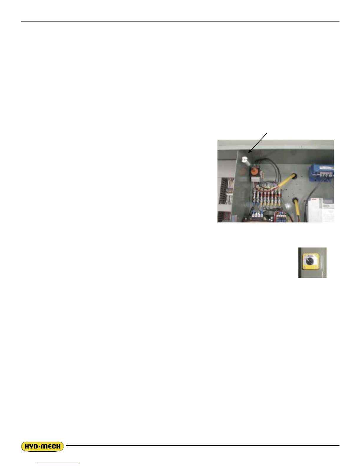
Power connection to the machine is made to the L1, L2, L3 and
ground terminals located inside the control panel and next to the
fuse holders as shown in the photo.
BLADE TENSION CHECK
When the machine is rst started, the head must be swung to the vertical position so the
blade position can be checked. Open the door at the top of the head and see that the blade
has not moved off of the wheel. It should not be overhanging from the wheel more that 1/4”,
if it is, then consult page 32 in Section 3. If it has stayed in its correct position, then turn the
Blade tension
blade tension switch to the “+” and close the door.
EARTH GROUNDING PROCEDURE
1. Customer to provide and install a ground rod approx. 60 (15mm) diameter, copper clad steel, to be
driven no less than 8’ (2.5m) into the ground, no more than 10’ (3m) away from control enclosure.
2. Ground rod to be connected to customer’s in plant ground system. This connection shall be made directly at the ground rod (if applicable).
3. It is desirable that the overall resistance to ground measured at the ground rod does not exceed 3
ohms. Customer is advised to consult local power company for further information on grounding.
4. Ground rod to be connected to ground terminal in control enclosure using insulated, stranded copper
wire. The correct wire size is shown.
Machine FLA 5A 10A 20A 30A 40A
Wire Size AWG 20 18 16 14 12
1.4

An additional point to check is ensuring continuity of ground within control enclosure. Start with main power
entrance ground terminal where internal ground conductors should originate and connect to, DIN terminal strip,
control transformer and the lid of control enclosure. Also PLC and Interface units should have their own ground
conductors connected to one of the main ground terminals.
Properly functioning ground system will;
• Provide safety for personnel.
• Ensure correct operation of electrical/electronic devices.
• Prevent damage to electrical/electronic apparatus.
• Help dissipate lightning strokes.
• Divert stray radio frequency (RF) energy from electronic/control equipment.
1.5

SECTION 2, OPERATING INSTRUCTIONS
START-UP
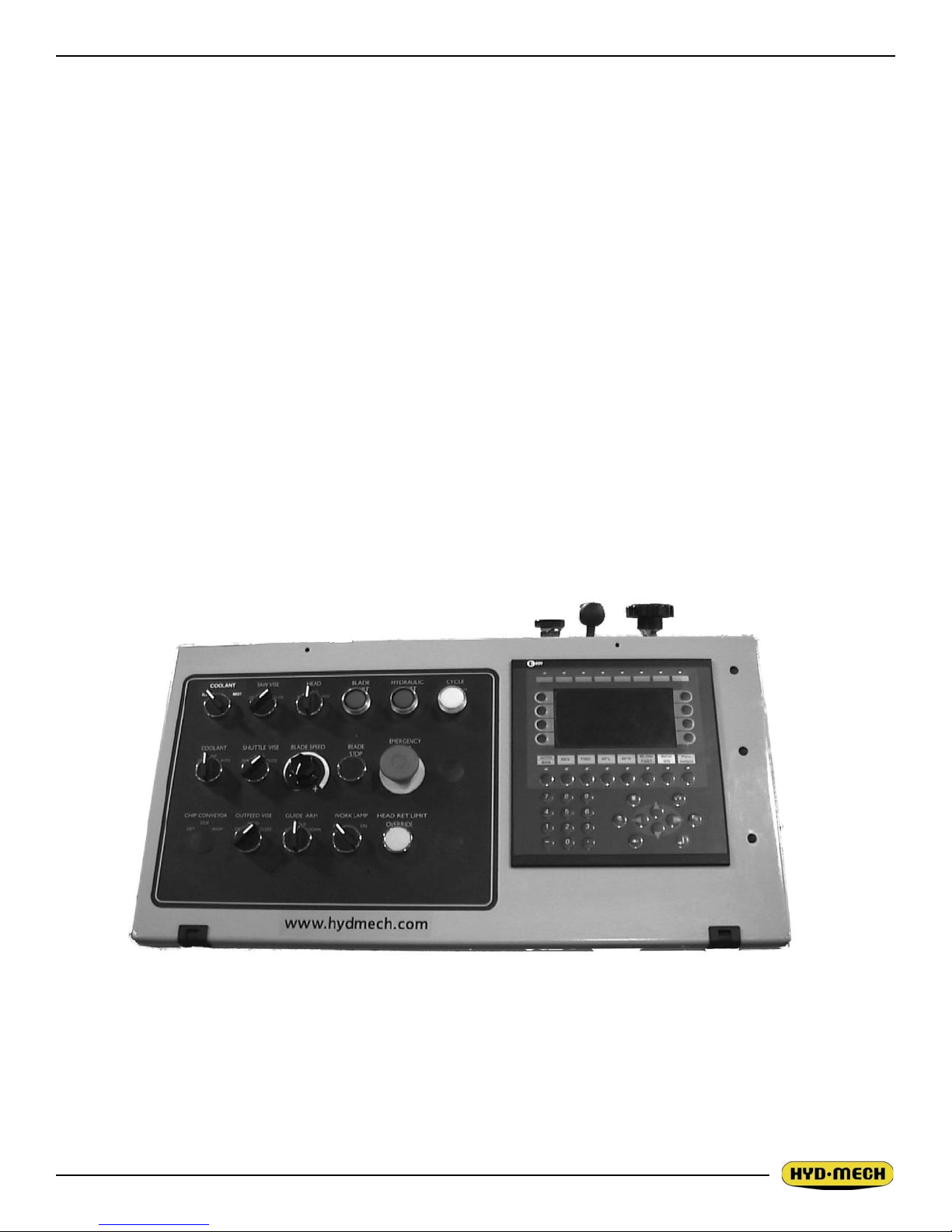
The V-18A PC II control console has been designed to simplify the operation of the saw, to give the operator
the ability to stop any function at any time, and to be able to control all the functions remotely.
We cannot overstress the importance of familiarizing yourself with the controls of the V-18A PC II prior to starting the machine.
NOTES:
1. WHEN STARTING THE MACHINE FOR THE FIRST TIME MAKE SURE THE BLADE IS MOVING
IN A COUNTER CLOCKWISE DIRECTION, AND THAT THE HYDRAULIC PRESSURE IS 900 PSI
(6200kP). IF THERE IS NO IMMEDIATE PRESSURE, SHUT THE SAW DOWN AND CHANGE THE
PHASE ORDER AS STATED ON Pg. 1.4.
2. FOR THE V-18APC, ALL SWITCHES MUST BE IN THE CENTER NEUTRAL POSITION TO START
THE MACHINE!
2.1

2.3
OPERATOR PANEL SWITCHES
TOP ROW
SAW VISE - (vise between the shuttle & outfeed vises) This switch has three positions, OPEN,
HOLD and CLOSE. With the switch held in the OPEN position the vise will open all the way or
until the switch is released. With the switch in the HOLD position, the vise will stay where it is
and will not move freely although it will not resist a large force indenitely without creeping. In
CLOSE, the vise will close all the way, or until it encounters enough resistance to stop it.
HEAD CONTROL - This switch has three positions: RET, HOLD and ADV. The switch is inactive unless the PLC is in manual mode. In the RET. position, the head will go to the back until
the switch is returned to “HOLD”. In the HOLD position the head will stay still. In the ADV. position, the head will move forward until it reaches the Head home position. The speed of descent
is controlled by the Head Feed and Head Force Limit controls.
BLADE START - The blade can be started only when the hydraulics are running in either
manual or auto mode.
NOTE: In automatic Mode the head will not descend until the blade has been started, which the
PLC will prompt the operator to do so.
HYDRAULIC START - To start the hydraulic system, the switches for the head and both vises
must be in the “NEUTRAL” position. The “HYDRAULIC START” button must be depressed and
held in momentarily until the PLC display becomes active.
CYCLE START / PAUSE - This button starts the cutting cycles and will stay illuminated white
until the cycles are completed. The PLC control system will prompt you to start the blade if it is
not running. The machine will then begin the automatic cycle until completed when it will shut
itself off. The current cycle can be PAUSED by pressing this button at any time during a cycle
and restarted by pressing it again.
CENTER ROW
COOLANT - This switch has three positions, WASH, OFF, and ON. In the WASH position, the
coolant system will operate when there is power to the machine, this allows using the wash gun
to clean the machine. In the OFF position, the coolant system is inactive. In the ON position the
coolant system will only run when the head is descending. This minimizes coolant carry over on
the stock.
SHUTTLE VISE - This switch has three positions, OPEN, HOLD and CLOSE. With the switch
held in the OPEN position the vise will open all the way or until the switch is released. With the
switch in the HOLD position, the vise will stay where it is and will not move freely although it will
not resist a large force indenitely without creeping. In CLOSE, the vise will close all the way, or
until it encounters enough resistance to stop it.
BLADE SPEED - This option is the REMOTE BLADE SPEED. This dial will increase or decrease the speed at any time while the blade is running.
2.2

BLADE STOP BUTTON - Stops the blade. If the blade is stopped during a cycle, the cycle will
continue but will not let the head descend until the blade is started
EMERGENCY STOP - This mushroom button stops the blade and hydraulic motors. Both vises
will hold their position but pressure will begin to fall off. Long pieces of work should always be
supported so they will not become loose over time and fall while the machine is shut down.
BOTTOM ROW
CHIP CONVEYOR - This switch controls the optional hydraulic chip conveyor. The chips can be
emptied to the left or right of the saw.
OUTFEED VISE - This switch has three positions, OPEN, HOLD and CLOSE. With the switch
held in the OPEN position the vise will open all the way or until the switch is released. With the
switch in the HOLD position, the vise will stay where it is and will not move freely although it will
not resist a large force indenitely without creeping. In CLOSE, the vise will close all the way, or
until it encounters enough resistance to stop it.
GUIDE ARM - This switch controls the position of the distance between the guide arms by moving the upper guide arm.
WORK LAMP - This option switch has two positions, OFF and ON.
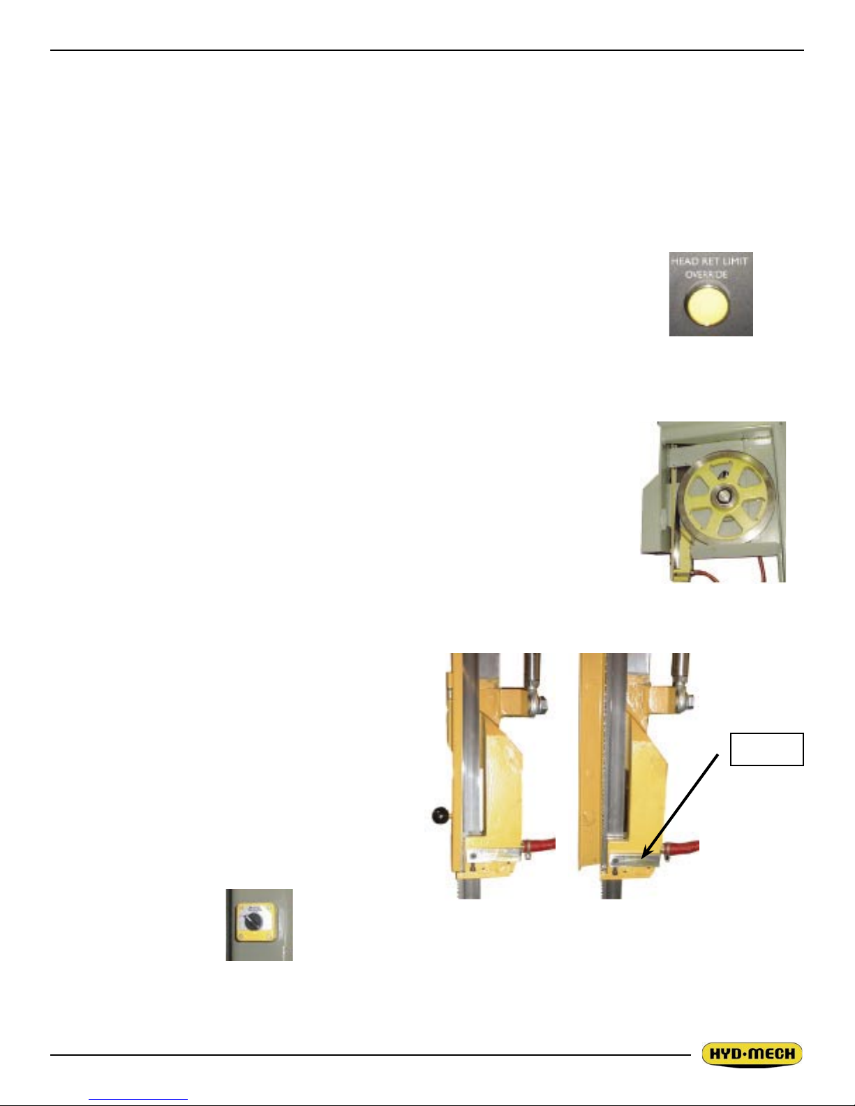
HEAD RETRACT LIMIT OVERRIDE - This button overrides the head retract limit switch to
allow the head to retract further in order to allow easier blade removal. Depressing this button
and either one of the head swing buttons simultaneously will also allow the head to swing at
any point along the travel of the head.
Note: These instructions are specic to the V-18APC bandsaw with serial numbers beginning
with: Serial # K0797074
2.3
2.5
OPERATION OVERVIEW
The PLC is a programmable length controller which allows the operator to run the machine in both manual and
automatic modes.
In manual mode, all functions can be operated by using a combination of selector switches on the control console and the PLC function buttons. Also the operator has the ability to execute a single cut utilizing a preprogrammed “Single Part Cycle”.
In automatic mode, the PLC has the capacity to program and store 99 jobs. Designated job numbers can be
programmed for quantity required (maximum of 999 pieces). Piece lengths from 0” to 220” (5588mm) and
angle of cut from 90° through to 45°.. Jobs can be run individually or in a QUEUE which allows a maximum of
5 jobs to run consecutively.
NOTE: If an emergency situation arises during any operation, use the large red mushroom “emergency stop”
button located on the control panel to shut down the machine.
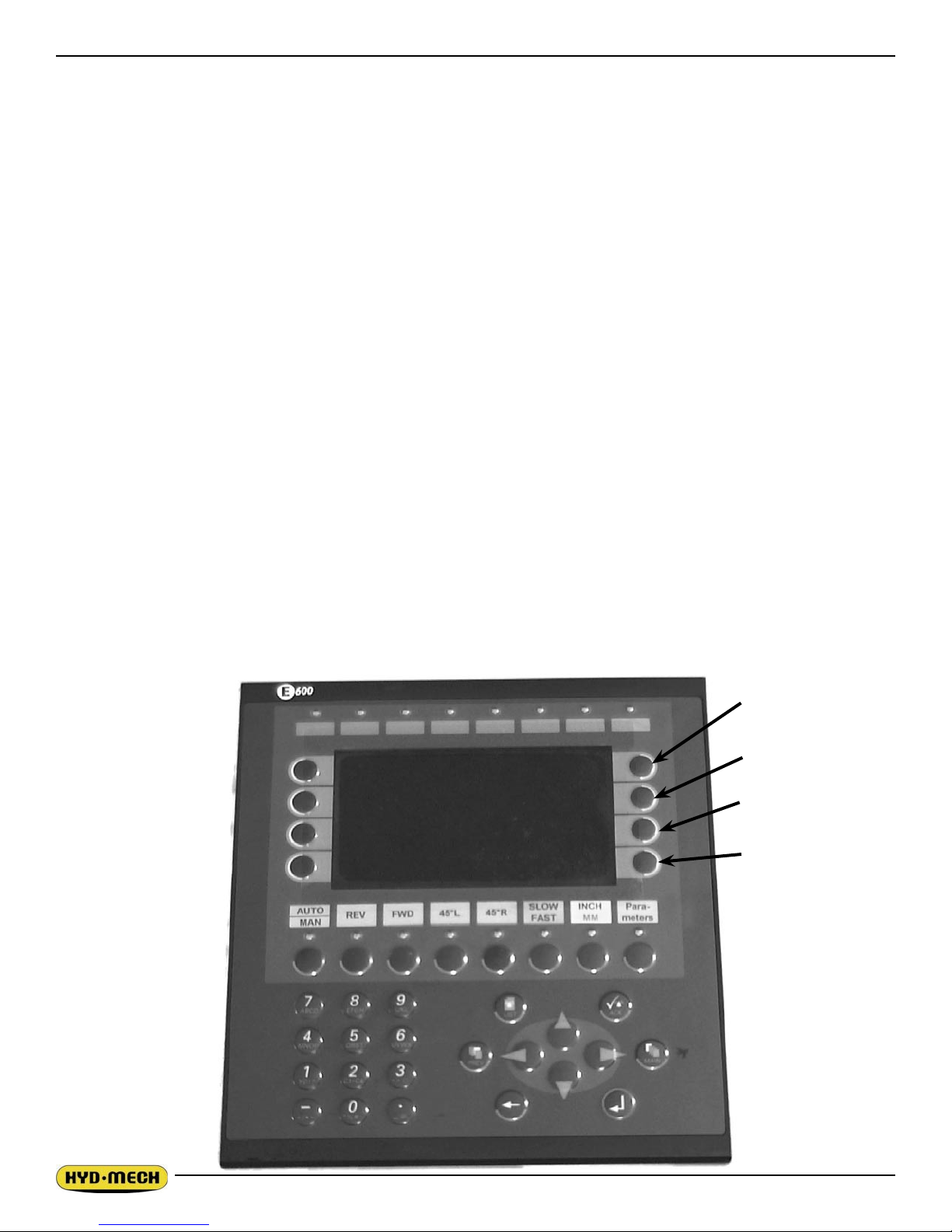
PLC CONTROL DESCRIPTION
PLC 500 CONTROL PANEL
All key functions are explained in detail the on following pages.
ACTIVATING THE PLC
The PLC control will become active when all selector switches are in the neutral position and the HYDRAULIC START button is depressed and “held in” momentarily. If the head is not in the 90° position, a screen will
prompt you to “SWING THE HEAD THROUGH 90 DEGREES”, using the 45L or 45R button, approach 90°.
When the head is at 90°, the AUTO/MAN indicator light will be green, all MANUAL controls are enabled, and
the MANUAL MODE STATUS screen will appear as shown. The length value (shuttle vise position) will display
the previous positions. To reset or clear the length value, press the F5 key.
F1
F2
F3
F4
2.4

FUNCTION BUTTON DESCRIPTION
On the dual function buttons, if a green indicator light is illuminated, it means that the function
printed in green on the top of the button is enabled. A red light indicates the function printed in
red at the bottom of that button is enabled.
•
•
•
•
MAN
AUTO
FWD
REV
45L
MANUAL MODE
(Green light) - Enables all control switches and PLC function buttons. Also stops an automatic
job in progress by switching to MANUAL.
AUTO MODE
(Red light) - Puts the machine in AUTO MODE and disables all manual functions.
The front vise selector switch must be in the closed position.
MANUAL MODE
This button will advance the shuttle toward the head (home position).
AUTO MODE
Button is disabled.
MANUAL MODE
This button will retract the shuttle away from the head.
AUTO MODE
Button is disabled.
MANUAL MODE
This button will swing the head toward 45O left.
AUTO MODE
Button is disabled.
•
•
•
•
45R
SLOW
FAST
INCH
METRIC
F1
MANUAL MODE
This button will swing the head toward 45O right.
AUTO MODE
Button is disabled.
MANUAL MODE
Green light indicates that the shuttle movement and head swing will move at a slow speed.
Red light indicates that the same movements will be at a fast speed.
AUTO MODE
Button is disabled.
MANUAL MODE/AUTO MODE
Green light indicates Imperial values.
Red light indicates Metric values.
AUTO MODE
Energizes CYCLE START button.
MANUAL MODE
No function.
2.5
2.7
F2
•
MANUAL MODE
After entering an angle value, pressing F2 will cause the screen to read “TO INTIATE MOVEMENT TO XX.X DEGREES PRESS CYCLE START”. Upon pressing “CYCLE START” the
head will swing to the programmed angle.
AUTO MODE
Used to scroll up through job information.
F3
•
F4
•
SINGLE PART CYCLE OPERATION
MANUAL MODE
Used for accessing the KERF screen. The KERF screen cannot be accessed while in METRIC mode and any change made to the KERF value will not be accepted by the controller
until it has been shut down and restarted.
AUTO MODE
Used to scroll down through job information
MANUAL MODE
Used to clear the length display (shuttle vise position) value.
Used to exit “MOVEMENT TO ANGLE” screen.
AUTO MODE
Used to CLEAR job or QUEUE values at the cursor position.
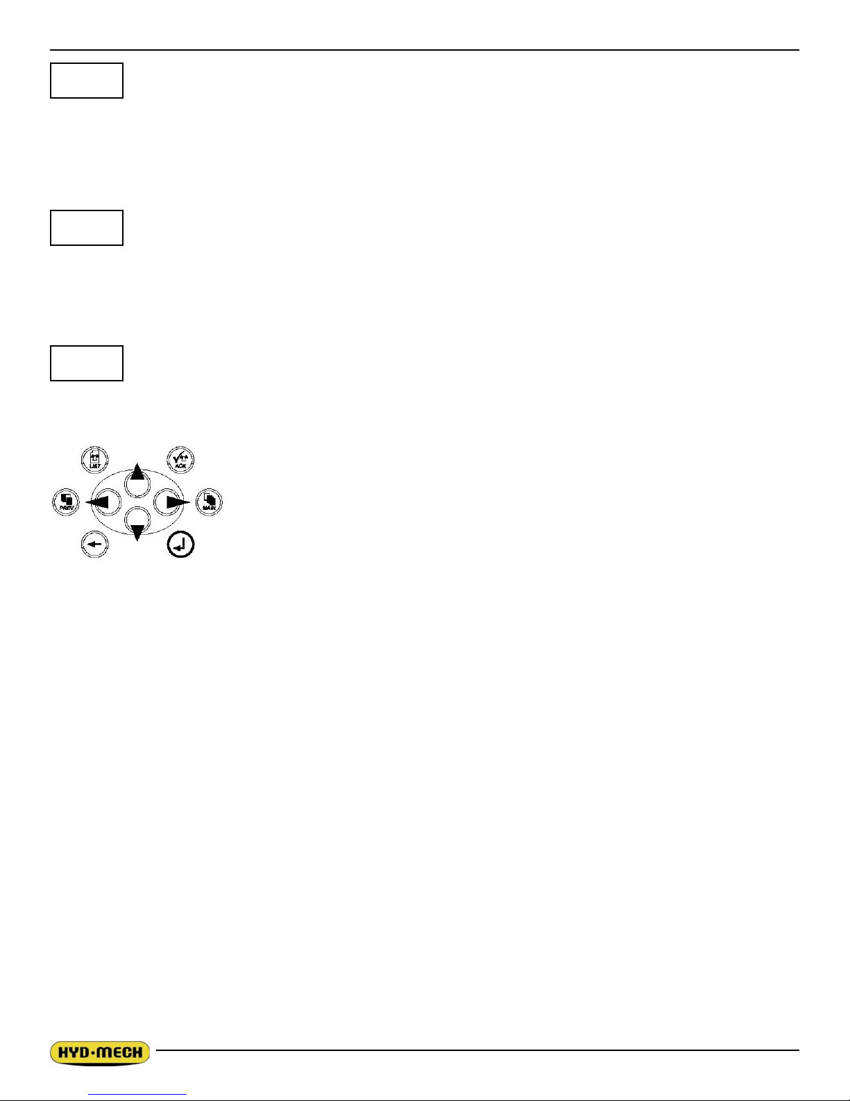
CURSOR KEY PAD - The cursor keys are used to navigate the cursor box on the
screen. If the display has columns, only the UP and DOWN keys are activated. If the
display has both rows and columns, then all four cursor keys are activated. The double vertical cursor keys are used to PAGE UP and DOWN. Depressing the PAGE
DOWN cursor key will cause the cursor to go to the bottom of the column it is in.
In MAN mode, the PLC allows the operator to initiate a “Single Part Cycle “ to cut one piece at a desired
length. To accomplish this, follow this procedure.
1. Position the head for the required angle by using the 45L or 45R function keys. You can also accomplish this by moving the cursor to the “Angle Go” feature, input desired angle, press ENTER. To change
the L or R angle, press ENTER and the L or R will switch to the other. Then press F2. The screen will
display “TO INITIATE ANGLE MOVEMENT PRESS CYCLE START”. Press CYCLE START and the
head will travel to the displayed angle. Change the SAW VISE switch to “HOLD” to exit back to the
manual screen.
2. A trim cut should be made before initiating the “Single Part Cycle “ operation.
3. To enable the “SINGLE PART CYCLE”, the infeed vise must be in the CLOSED position.
4. Make sure the head is set so that the blade is behind and the guide arm is above the material and the
head selector switch is in the HOLD position.
5. To the left of the F1 button, the display will be ashing. Cursor the rectangular box to this section and
key in the desired length using the numeric key pad and press enter.
6. If the blade is not running, you will be prompted by the word “BLADE” ashing on the display window.
Start the blade and adjust the blade speed as required.
7. You will then be prompted by the word “START” ashing on the display window to begin the cut. Press
CYCLE START button and the cycle will begin. When the CYCLE START button is pressed, (if the
shuttle is not in HOME) the shuttle vise will move to the forward home position before executing the
2.6
length movement.
8. When the cut is completed, the head will retract, the blade will stop and the display window will reset for
the next cut.
9. To cut another job, repeat steps 1 through step 7.
NOTE: To cut multiple pieces, switch to AUTO and follow the automatic procedures.
AUTOMATIC OPERATION
To enter AUTO MODE, the saw vise switch must be in the closed position. Press the AUTO/MAN button, the
red indicator will come on, the screen will change to the PICK LIST display as shown on PAGE 11 and be
ready for editing or starting a new job. The VISE, HEAD and all MANUAL functions on the control panel are
disabled. At this point it is possible to edit an existing job or enter a new job.
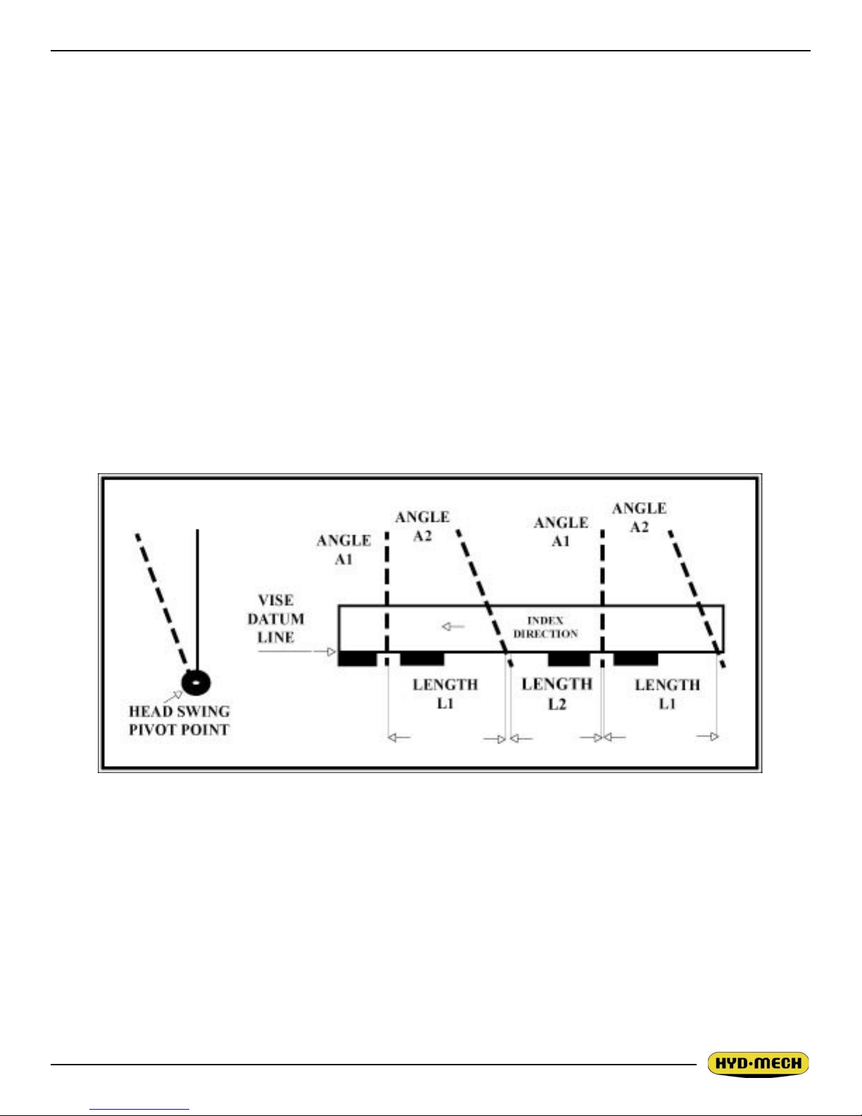
PROCEDURE FOR EDITING OR STARTING A NEW JOB IN AUTO MODE
Each job is dened by two angles and two lengths. Angle 1 (A1) is the rst angle to be cut (this will be the trim
cut). Length 1 (L1) is the length of the material to be cut as measured between the two intersection points of
the blade axis and the saw table datum line. Angle 2 (A2) is the second angle to be cut and length 2 (L2) again
is the length of material as measured between the two intersection points of the blade axis and the table datum
line.
2.7

2.9
PICK LIST SCREEN
1. Immediately after entering the AUTO mode, the PICK LIST screen will be displayed with the cursor
located at “A1 of JOB #1”. Both the ENTER button or the cursor key can be used to move through this
screen.
2. Enter proper “A1” value, press ENTER and the cursor will move to angle direction letter.
3. Press ENTER to toggle between R (right) and L (left). To move to “L1”, use the cursor key.
4. Enter proper “L1” value, press ENTER and the cursor will move to “A2”.
5. Enter proper “A2” value, press ENTER and the cursor will move to angle direction letter.
6. Press ENTER to toggle between R (right) and L (left). To move to “L2”, use the cursor key.
7. Enter proper value for “L2”, press ENTER and the cursor will move to “QTY REQ”.
8. Enter required quantity, press ENTER and the cursor will move to “QTY CUT”.
9. When starting a new job, zero out “QTY CUT” by entering “0”.
The job is now ready to start, or more jobs can be programmed at this time. If starting to run a single job,
press F5 to clear the QUEUE, move the cursor to the 1st JOB and key in the desired JOB # and press F1 INIT
(initiate) CYCLE. You will then be prompted to enter MATERIAL HEIGHT and press ENTER and then CYCLE
START. Then the blade must be started to run the JOB or QUEUE otherwise the head will not advance for the
cut.
If you wish to clear the values of any job, cursor to that job # and press F4.
NOTE: The cursor must be in the queue line and the QTY REQ must be more than QTY CUT to start a cycle.
When the AUTO cycle commences, the screen will change to the “AUTO MODE STATUS” screen (shown on
the next page) and the following events will take place:
1. The head will swing to “A1” to perform the rst cut (trim cut).
2. After the trim cut, the shuttle will advance the material to the “L1” value.
3. The head will swing to the “A2” value to make the second cut and complete the rst part.
4. The shuttle vise will advance to the “L2” value after the “A2” cut is done.
5. At completion of the “JOB”, the machine will shut off.
NOTES:
The CYCLE START button is used to PAUSE a JOB in progress. When a JOB is PAUSED the PICK LIST will
appear and the operator can make alterations to the job values which will take place on the next
2.8

WORKING WITH A QUEUE
The purpose of a QUEUE is to allow the operator to run several jobs (max of 5) in series if they are of like
material. To run a QUEUE, it is necessary to program in all job values as is done with programming a single
job. After the jobs are programmed in, scroll the cursor to the QUEUE, press F4 to clear the QUEUE and enter
the desired JOB #’s in desired sequence. To run the QUEUE, press F1, CYCLE START and start the blade.
You will be asked to “ENTER THE MATERIAL HEIGHT”, KEY IN THE VALUE AND PRESS enter. The AUTO
MODE STATUS screen will appear and display each individual JOB as it is being run. The STOP and PAUSE
functions are as described previously and at completion of the last JOB in the QUEUE, the machine will shut
off. The machine will automatically advance the stock between jobs for trim cuts as needed.
BLADE BASICS
This section has been prepared to give the operator the ability to set up the saw for most cutting situations.
The saw is equipped with variable blade speed control and hydraulic feed control, as well as an extensive door
chart to guide the operator to the correct setting of these controls.
Technology is rapidly changing all aspects of production machining. Metal cutoff is no exception. The advances made in the bandsaw blade industry have denitely brought down the cost per cut, despite the three
fold higher price of high technology blades. Variable pitch, bi-metal blades (like the 4/6 or 3/4 bi-metal blade
supplied with the saw) last much longer, cut faster, and more accurately than conventional carbon steel blades.
In order to take advantage of the superiority of bi-metal blades, it is critical to properly “break-in” a new blade.
This is accomplished by taking two or three cuts through solid four or ve inch diameter mild steel at an extremely slow feed rate. (It is also advisable to utilize a slow blade speed.)
These two or three slow cuts sufciently lap (polish) the new blade so that it does not snag the material being
cut. Proper break-in will alleviate blade vibration, improve surface nish, accuracy, and blade life.
After “break-in”, the following six points must be closely monitored to ensure long blade life:
1. Proper blade tension should be maintained. (see Section 3, Pg 3.1 Blade Changing)
2. Generous coolant application is essential with most materials. A high quality and well mixed coolant will
extend blade life, and also increase cutting rate and quality. On those materials where coolant is undesirable for cutting, a slight coolant ow or periodic oiling of the blade is necessary to prevent the blade
from being scored by the carbide guides.
3. The stock being cut must be securely clamped in the vises.
4. The proper feed force should be chosen. (see Saw Cutting Parameters: Step2)
5. The proper blade speed must be selected. (see Saw Cutting parameters: Step 4)
6. The proper feed rate must be applied. (see Saw Cutting Parameters: Step 5)
2.9
2.11
VARIABLE SPEED CONTROL
Blade speed can be adjusted innitely between 65 to 385 SFM (20 to 117m/min). Adjustment
should be made only when the blade is running. Clockwise rotation of dial on the control panel
increases blade speed while counter clockwise rotation decreases blade speed.
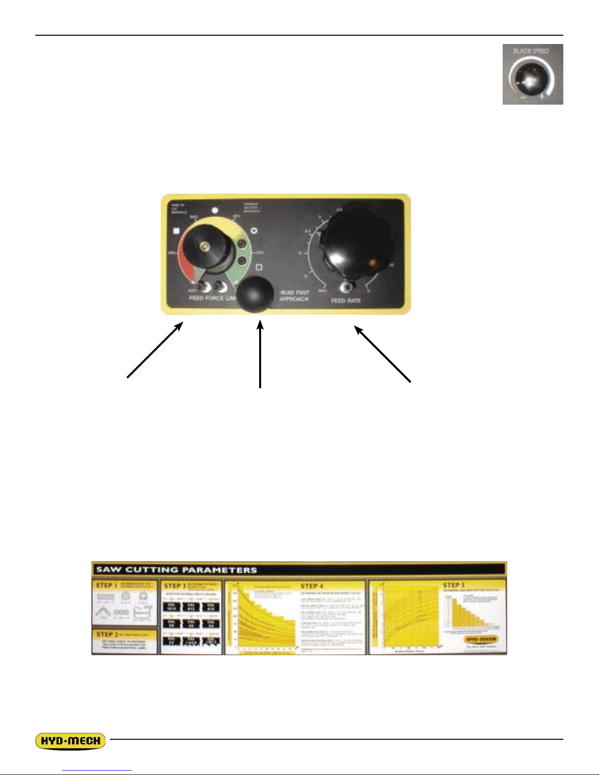
HYDRAULIC FEED CONTROL
The Hydraulic Feed Control is located to the top of the control panel. These controls allow independent control
of Feed Force and Feed Rate.
Feed Force Knob
Used to set Feed Force Limit
(counterclockwise rotation to
Fast Approach Lever
Depress for fast head approach.
Feed Rate Knob
Used to control the speed of
head advancement
increase and clockwise rotation to decrease).
CUTTING PARAMETERS CHART
A full size PARAMETERS CHART is mounted on the front base cover. The chart contains ve steps for the
operator to follow in order to achieve optimum performance of the saw. Details of these steps are explained in
detail beginning with step 1 below and on the following pages.
2.10
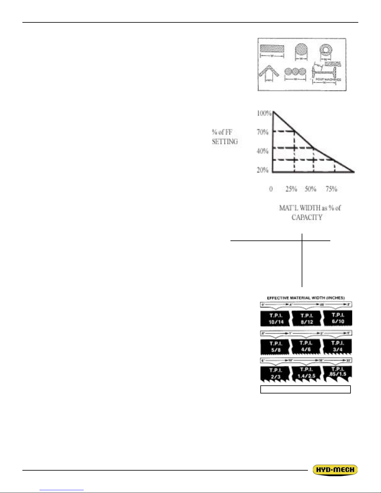
CHART EXAMPLE #1
We will use the parameters chart to set up the saw for cutting 8” (200mm)
Diameter #1045 Carbon Steel.
STEP 1, DETERMINE EFFECTIVE MATERIAL WIDTH - W (inches) or
(mm)
Effective material width, W (in.) for most common shapes of materials,
is the widest solid part of the material to be in contact with blade during
cutting. For simple shapes, as illustrated on the chart, this can be directly
measured. For bundles of tubes and structurals, measuring the effective
width is difcult. Effective width is 60% to 75% of the actual
material width.
NOTES:
1. Both effective material width and guide arm width are
used in setting the saw.
2. Guide arm width is the distance between the guide
arms and is used in STEP 2.
3. Effective material width, as determined here in STEP
1, can be thought of as the average width of material
“seen” by each tooth, and it is used in STEPS 3 and
4. In Example #1, for an 8” (200 mm) diameter solid,
Effective Material Width is 8” (200mm).
Material Width Chart
STEP 2, SET FEED FORCE LIMIT
The Feed Force Limit is the maximum amount of force with
which the head is allowed to push the blade into the workpiece. FEED FORCE LIMIT should be set with the head in the
down mode, according to the label.
CUTTING SOLIDS
For cutting solids, the wider the section, the less FF should be set,
to avoid blade overloading. See the graph.
BLADE FF
(1) OPTIMUM PITCH
20%
FROM STEP 3
(2) PITCH FINER
THAN OPTIMUM
0%
EXAMPLE: When cutting a solid which is 1/2 of machine capacity using the graph, locate 50% on the horizontal line and travel
upwards to the plotted line and then travel directly across to the vertical FF
Setting line. The point that you have arrived at shows a setting of 40% for a
piece 50% of capacity.
CUTTING STRUCTURALS
A reduced Feed Force Setting is used when cutting structurals:
For structurals, a blade ner than Optimum can be used for more efcient
cutting.
If a ner than optimum blade is going to be used, Feed Force Setting should
be reduced even further.
STEP 3, DETERMINE OPTIMUM BLADE PITCH - TEETH PER INCH
Optimum Blade Pitch (T.P.I.)
(T.P.I.)
Selecting a blade with proper tooth pitch is important in order to achieve optimal cutting rates and good blade
life.
For cutting narrow or thin wall structural materials a ne blade with many teeth per inch (T.P.I.) is recommended. For wide materials a blade with a coarse pitch should be used. The sketch can be referenced for the blade
pitch changes for differing effective material widths.
It is impractical to change the blade to the proper pitch every time a different width of material is cut and it is
not necessary, but remember that the optimum blade will cut most efciently. Too ne a blade must be fed
2.11

2.13
slower on wide material because the small
gullets between the teeth will get packed
with chips before they get across and out
of the cut. Too coarse a blade must be fed
slower because it has fewer teeth cutting
and there is a limit to the depth of a cut
taken by each tooth. Allowance for the use
of a non-optimum blade is made in STEP
5.
In our Example #1: Effective material
width of 8” (200 mm) & Optimum blade
has 2/3 teeth per inch.
STEP 4, DETERMINE OPTIMUM BLADE
SPEED, V (ft/min) (m/min)
The relationship between optimum blade
speed and effective material width for various materials is represented on the graph shown.
The graph shows that as effective material width gets wider or as material gets harder, lower blade speeds are
recommended. If material is narrow or soft, higher blades speeds should be selected.
In Example #1
• 8” (200mm) diameter #1045 Medium Carbon Steel solid bar is to be cut.
• On the graph above nd the Medium Carbon Steel Curve which represents the optimum blade speeds
for 1045 Carbon Steel.
• On the horizontal axis (effective material width axis) nd number 8 which represents effective material
width of an 8” (200mm) diameter solid.
• Find the point where a vertical line from 8” (200mm) intersects the Medium Carbon Steel Curve.
• From this intersection point run horizontally left to the vertical axis (optimum blade speed axis) and nd
the point marked “200”.
• For 8” (200mm) diameter, 1045 Carbon Steel solid bar 200 ft/min (60m/min) is the optimum blade
speed.
NOTE:
Higher than optimum blade speed will cause rapid blade dulling. Lower than optimum blade speeds reduce
cutting rates proportionately and do not result in signicantly longer blade life except where there is a vibration
problem. If the blade vibrates appreciably at optimum speed as most often occurs with structurals and bundles,
a lower blade speed may reduce vibration and prevent premature blade failure.
Material Hardness - The graph above illustrates blade speed curves for materials of hardness 20 RC (225 Bhn)
or lower. If the material is hardened then the multipliers need to be used. These multipliers are given in the
NOTE at the bottom right of the graph. As the hardness increases the optimum blade speed decreases.
The following table gives examples of the optimum blade speeds for different materials.
NO. MATERIALS OPTIMUM BLADE SPEED
ft/min m/min
1 5” (125mm) Dia Solid Carbon Steel 225 70
2 12” (300mm) I-Beam 290 90
3 4” x 4”(100 x 100mm) Rec Tube, 1/4” (6mm) Wall 350 110
4 4”(100) 400 Stainless Steel 140 45
5 2” x 2” (50 x 50mm) Rec Tube 1/4” (6mm) Wall
Bundle 5 x 5 pcs 10” x 10” (500 x 500mm) 325 100
6 3” x 3” (75 x 75mm) Inconel 60 20
2.12
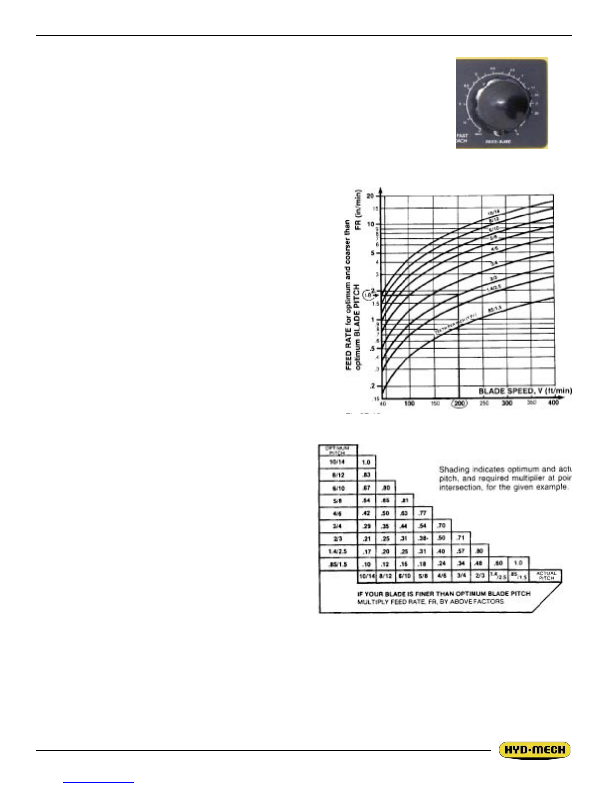
STEP 5, DETERMINE FEED RATE SETTING, FR (in/min) (mm/min).
FEED RATE is the vertical speed at which the blade descends through the workpiece.
The FEED RATE Knob controls FEED RATE of the blade descent in the range 0
to 15 in/min (380mm/min). The FEED RATE should be adjusted only in one direction (from “O” to required value). If you go too far, go back to “O” and come back
up. To set FEED RATE for particular cutting situations use the Graph below, which
represents the relationship between FEED RATE, blade
speed and blade pitch.
For Example #1, it is known from Step 3 that optimum blade
pitch is 2/3, and from Step 4 that blade speed, is 200 ft/min
(60mm/min). From the Graph on the left, the FEED RATE is
determined in the following way:
On the horizontal axis (blade speed axis), nd 200 ft/
min(60mm/min).
Find the point where a vertical line from 200 ft/min (60mm/
min) would intersect the 2/3 blade pitch curve.
Feed Rate Knob
From this intersection point run horizontally left to the vertical
(FEED RATE) axis, to arrive at 1.8 in/min (45mm/min) FEED
RATE. Thus 1.8 in/min (45mm/min) is the FEED RATE for
cutting 8” (200mm) diameter 1045 Carbon Steel when the
optimum 2/3 pitch blade is used.
Feed Rate Calculation
If the saw is tted with a blade coarser than optimum
(e.g.. 1.4/2.5 TPI) we can still use the graph, but we go
to the 1.4/2.5 curve. As a result we nd that the FEED
RATE is decreased to 1.3 in/min (133mm/min) for this
blade. If however, the machine is tted with a ner than
optimum blade (e.g. 3/4 TPI) we use the graph for the
optimum blade as before, and then use a multiplier
given by the table below.
NOTE:
Use the following chart when cutting solids. For structurals, see “CUTTING STRUCTURALS” in STEP 2.
ADDITIONAL CUTTING SETUP EXAMPLES
Optimum versus Actual Blade Pitch
EXAMPLE # 2
Material Round Steel Tube SAE 4320 - Hardened
to 35 RC (325 Bhn)
Dimensions - 6” O.D. x 4” I.D. (150mm O.D. x 100mm I.D.)
STEP I Effective Material Width: 4 1/2” (.75 X 6) 114mm (19 x 6)
STEP 2 Feed Force limit setting for 6” Diameter material Refer to Feed Force Limit, Setting in Step 2
2.13
2.15
STEP 3 Optimum blade pitch (TPI): 3/4 T. P. I.
Actual blade pitch on the saw: 4/6 T. P. I.
STEP 4 Optimum blade speed for 4 1/2” effective 225 ft/min (70 m/min) material width
Blade speed reduced by hardness factor: 225 ft/min X .60 = 135 ft/min
(70 m/min x .60 = 42 m/min)
STEP 5 Feed Rate for 3/4 TPI blade: 1.8 in/min (45 mm/min)
Feed Rate for 4/6 TPI blade: 1.8 in/min X .70 = 1.3 in/min
(reduced by ner than optimum blade pitch factor) (45 mm/min x .70= 31.5 mm/min)
EXAMPLE # 3
Material Bundle -Low carbon steel 2” x 2” Tube with 1/4” wall, 12 piece bundle
(50 mm x 50 mm with 6 mm wall)
Dimensions 6” x 8” (150 mm x 200 mm)
STEP I Effective Material Width: 5” (.6 X 8”) 120 mm (.6 x 200)
STEP 2 Feed Force limit setting for 8” Diameter material. Refer to Feed Force Limit Setting in Step 2
STEP 3 Optimum blade pitch (TPI): 3/4 T. P. I.
STEP 4 Optimum blade speed for 5 “effective material width - 320 ft/min (100 m/min)
STEP 5 Feed Rate for 3/4 TPI blade: 4.0 in/min (100 mm/min)
COOLANT FLOW
A generous ow of coolant should be applied in order to increase production and blade life. The machine is provided with an independently controlled
coolant spout. This spout should always ood the blade with coolant. Slight
adjustment may be required when changing the blade speed. A properly
adjusted ow of coolant should cover the blade which in turn will carry it into
the cutting area. Flow adjusting tap is shown at Console side in the photo.
NOTE: When cutting materials that do not need coolant (cast iron) some
coolant ow is required to provide blade lubrication in order to prevent blade
scoring by the carbides.
Coolant valve and wash hose
HEAD BACK LIMIT ADJUSTMENT
For machines with the canted head option, the blade is further from the
material at the table than it is at the top of the guide arm height. The higher the material height, the farther back the head must travel to allow the
material to clear the blade when it is being shuttled forward. When cutting
lower materials, the head back travel distance can be limited and thereby
reduce the cycle time for each cut. The head back limit handle (located at
the opposite side of the base from the conveyor) is pulled up (full back) or
pushed down.
With the handle pulled fully up, fully retract the head. Load and close the
vise on the material, advance the head so the blade is approximately 1/4”
from the material at its highest point. Push the handle fully down, switch
the head control to “RET” and pull the handle up slowly until the head
begins to retract. At this point the handle should be turned (either way) to
lock its position. This procedure should be repeated whenever different
material is to be cut.
Head back adjustor shown on
the right side.
2.14

CHIP CONVEYOR
The chips generated while sawing can be removed from the bottom of the machine with the help of the optional
chip conveyor. Rotation of the chip conveyor crank will
operate the conveyor in the direction of rotation of the
crank. A chip bucket is included with the chip conveyor
option. The crank handle and chip bucket are shown
below.
HYDRAULIC CHIP CONVEYOR
An option available with the V-18 II is the hydraulic
chip conveyor drive which provides an easier means
of cleaning out the chips that accumulate while cutting. A Chip Conveyor control switch for the hydraulically driven chip conveyor is located on the operator
control panel.
Manual chip conveyor handle and chip bucket.
2.15

SECTION 3, MAINTENANCE AND TROUBLESHOOTING
BLADE CHANGING
We cannot overstress the safety precautions which should be followed during this operation. Safety glasses,
gloves as well as a long sleeve shirt should be worn. The hydraulics should be off at all times when the operator has his/her hands in contact with the blade. With safety in mind, the following procedure should be followed:
STEP ONE, Head Retract
Position the Head in the full retract position. This will drive the Head past the Head
Back Limit Switch creating a wider gap between the blade and the cutting table allowing easier removal of the blade.
Note: Close the right side saw vise to protect the cylinder rod during blade change.
Press the HEAD RETRACT LIMIT OVER RIDE button on the operator panel.
STEP TWO, Open Doors
The blade on the V-18APC II travels around two blade wheels, the bottom Drive
wheel and the top Idler wheel. Both of these wheels are housed in compartments
with locking doors. The photo shows the top Idler wheel with the door open.
Head return limit over
ride button
STEP THREE, Open Blade Guard
The V-18APC II blade is only exposed to the operator at the cutting area. A hinged
cover protects the operator from the blade between the Idler wheel assembly and
the actual cutting area. A black knob on the cover allows it to be easily pulled open.
STEP FOUR, Release Carbides
It is necessary to release the carbides from the locked position so that the blade can
be easily removed. As shown in the photo, the carbides are released by turning the
lock bars 270° counter-clockwise. The top carbide
lever is shown in the photo. The bottom lock lever
is on the lower guide arm.
STEP FIVE, Blade Tension
To remove the blade the blade tension must be
released. The Blade Tension selector switch is a
three position switch. The “+/RUN” position is for
the normal operation of the V-18APC II. The “- “
position is for releasing the tension and the switch
must be in this position to change the blade.
Idler wheel door
opened.
Locking
Lever
Blade tension switch
The blade guard closed and open with the
carbide locking lever in the locked position.
3.1
3.3
STEP SIX
Remove the blade from the carbide guides by pulling out.
STEP SEVEN
Remove the blade off of the wheels. Gloves are a necessity.
STEP EIGHT
Place the new blade onto the wheels in correct orientation, teeth pointing down as they pass through the
guides and facing the operator.
STEP NINE
Turn hydraulics ON. Tension partially. Turn hydraulics OFF.
STEP TEN
Place the new blade into the carbide guides (by twisting the blade) until seated.
STEP ELEVEN
Turn hydraulics ON. Set Blade Tension switch to “+/RUN”.
STEP TWELVE
Start the blade for a few rotations. This allows the blade to fully seat in the carbide guides and track onto the
wheels.
FINAL STEP
Close the carbide guide locks, close the blade guard and close the Idler and Drive doors. Break-in blade.
BLADE TRACKING
First, inspect the blade wheels for wear or damage and repair as required. Blade tracking adjustment should
always begin at the wheel where the tracking is farthest out of specication. Using the instructions below,
adjust the worst wheel, jog the blade and check both wheels. Repeat this process until both wheels are within
specication (.200-220” of tooth over hang from the front of the wheel). Both the drive and idler wheels are fac
tory set a certain distance from the wall behind the wheel. Adjustment should not be required unless the wheel
is being replaced. On the drive wheel there is a large hex head bolt and four set screws in a “push/pull” ar
rangement. For the idler wheel there is single adjuster assembly in the centre of the idler shaft under the cover
on the front of the head. Hyd·Mech Service should be contacted before making any adjustment to the wheel
position.
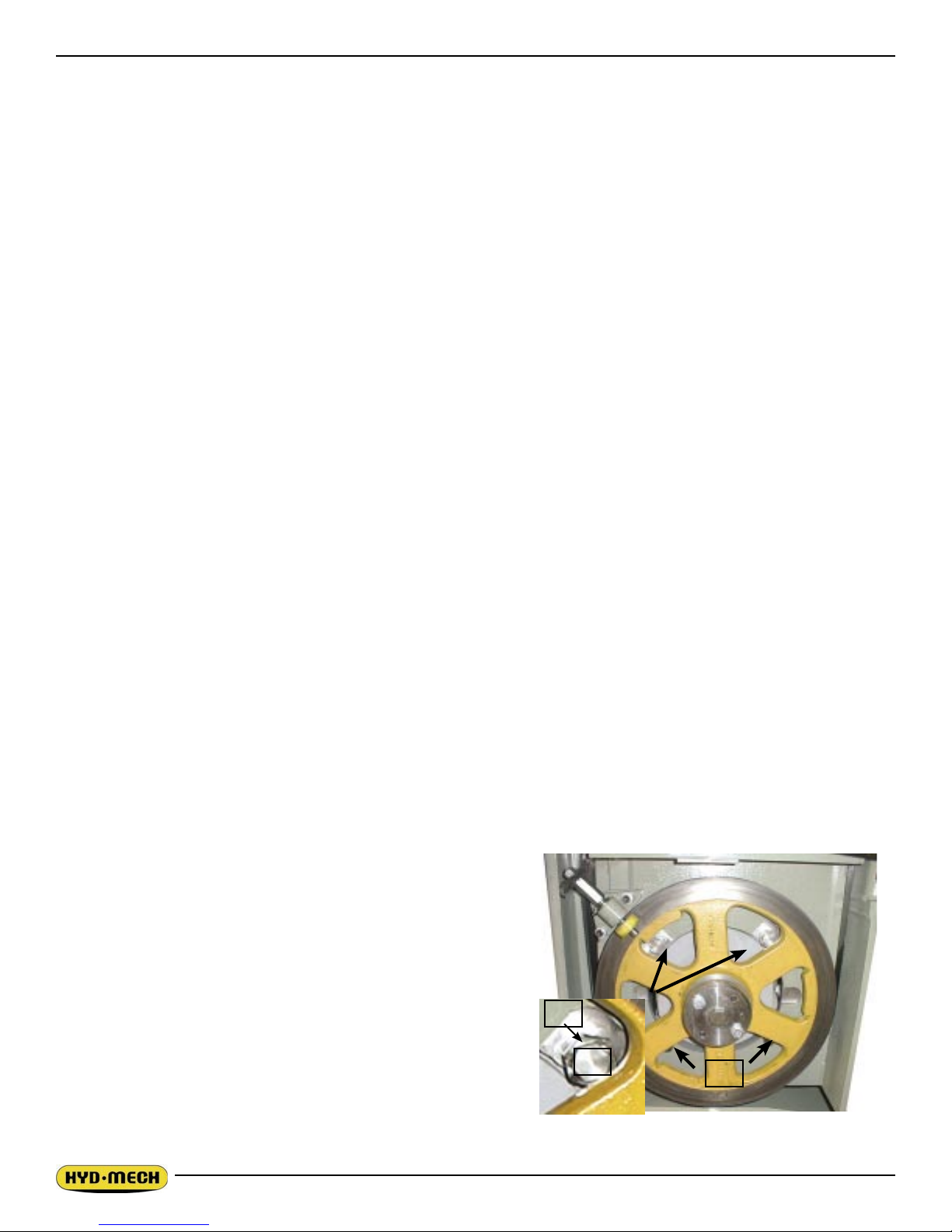
DRIVE WHEEL ADJUSTMENT
Adjustments should be made with the blade tension released
slightly. The drive wheel has two mounting bolts and two
adjusting bolt assemblies. The mounting bolts (A) should be
loosened but remain snug before making any adjustment
to the bolt assemblies (B & C). Both of the bolt assemblies
should be adjusted by equal amounts. To adjust the bolt as
C
semblies, release blade tension slightly, loosen bolts “B” and
turn bolts “C” in or out by equal amounts and tighten bolts “B”.
Turning bolts “C” out will pull the blade onto the wheel and
B
A
turning them in will push the blade off the wheel. Check the
tracking movement after each one quarter turn of bolts “C” by
-
3.2
Drive wheel mounting bolts and track-
ing bolt assemblies.
 Loading...