

Hyd-Mech V18 User Manual

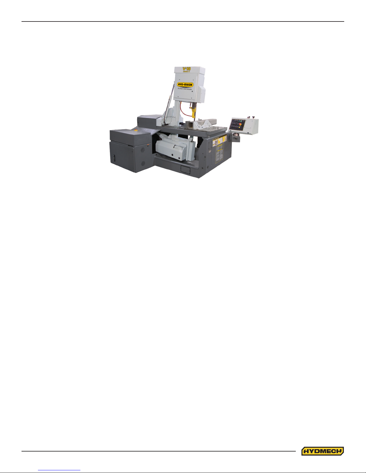
V18
393433
THANK YOU,
On behalf of everyone at HYD·MECH Group Limited, we would like to thank and congratulate you on your decision to
purchase a HYD·MECH bandsaw.
Your new machine is now ready to play a key role in increasing the eciency of your operation, helping you to reduce cost
while boosting quality and productivity.
To ensure you are maximizing the power and versatility of your new HYD·MECH bandsaw, please take the time to
familiarize yourself and your employees with the correct operation and maintenance procedures as outlined in this
manual. Please keep this instruction manual for future reference in a known location and easily accessible to all users of
the device.
HYD·MECH oers a great variety of options, components, and features for its various models. Therefore, some of the
equipment described in this manual (various illustrations and drawings) may not be applicable to your particular machine.
The information and specications provided in this manual were accurate at the time of printing. HYD·MECH reserves the
right to discontinue or change specications or design at any time without notice and without incurring any obligation.
Thank you.
Hyd·Mech Group Limited
P.O. Box 1659, 1079 Parkinson Road
Woodstock, Ontario, N4S 0A9
Phone : (519) 539-6341
Service : 1-877-237-0914
Sales : 1-877-276-SAWS (7297)
Fax : (519) 539-5126
e-mail : info@hydmech.com
Printed JULY 2016
1

2

2

TABLE OF CONTENTS
SECTION 0 - SAFETY INSTRUCTIONS
SUMMARY .......................................................................................................................................0.1
BASIC RULES ..................................................................................................................................0.3
RESPONSIBILITIES OF THE OWNER ............................................................................................0.3
RESPONSIBILITIES OF THE OPERATOR AND MAINTENANCE PERSONNEL ...........................0.4
SAFETY HAZARD LABELS .............................................................................................................0.6
SECTION 1 - INSTALLATION
SAFETY CONSIDERATIONS ..........................................................................................................1.1
LIFTING AND SHIPPING .................................................................................................................1.2
REMOVING HEAD RESTRAINT ......................................................................................................1.2
INSTALLATION OF THE CONTROL PANEL ...................................................................................1.3
LEVELLING THE V18 ......................................................................................................................1.4
HYDRAULIC OIL ..............................................................................................................................1.4
CUTTING FLUID ..............................................................................................................................1.4
WIRING CONNECTIONS .................................................................................................................1.5
BLADE TENSION CHECK ...............................................................................................................1.5
EARTH GROUNDING PROCEDURE ..............................................................................................1.5
SECTION 2 - OPERATING INSTRUCTIONS
START-UP ........................................................................................................................................2.1
CONTROL CONSOLE .....................................................................................................................2.1
SAW CUTTING CONTROLS ...........................................................................................................2.2
HYDRAULIC FEED CONTROL ........................................................................................................2.2
MANUAL OPERATION CONTROLS ................................................................................................2.2
ADDITIONAL MANUAL CONTROLS ...............................................................................................2.5
BLADE BASICS................................................................................................................................2.6
CUTTING PARAMETERS CHART ...................................................................................................2.6
MECHANICAL CONTROLS ............................................................................................................2.11
HEAD FORWARD LIMIT SETTING ................................................................................................2.11
CHIP CONVEYOR (OPTIONAL) .....................................................................................................2.11
HYDRAULIC CHIP CONVEYOR (OPTIONAL) ...............................................................................2.11
COOLANT FLOW ............................................................................................................................2.11
HEAD SWING BRAKE ....................................................................................................................2.12
i

SECTION 3 - MAINTENANCE AND TROUBLE SHOOTING
LOCK-OUT .......................................................................................................................................3.1
LOCK OUT PROCEDURE ...............................................................................................................3.1
BLADE CHANGE PROCEDURE .....................................................................................................3.2
BLADE INSTALLATION ....................................................................................................................3.3
BLADE TRACKING ..........................................................................................................................3.3
DRIVE WHEEL ADJUSTMENT ........................................................................................................3.3
IDLER WHEEL ADJUSTMENT ........................................................................................................3.4
BLADE BRUSH ADJUSTMENT .......................................................................................................3.4
BLADE GUIDES ...............................................................................................................................3.4
GEARBOX LUBRICATION (V18 WITH A412 GEARBOX) ...............................................................3.5
LUBRICATION ..................................................................................................................................3.5
HYDRAULIC MAINTENANCE ..........................................................................................................3.6
TROUBLE SHOOTING GUIDE ........................................................................................................3.7
ELECTRICAL TROUBLESHOOTING ..............................................................................................3.7
CUTTING AND BLADE TROUBLESHOOTING ...............................................................................3.8
SERVICE RECORD & NOTES .......................................................................................................3.10
SECTION 4 - ELECTRICAL
V18 COMPONENT LOCATION ........................................................................................................4.1
FOR ELECTRICAL SCHEMATICS AND PARTS LIST SEE PDF ON ATTACHED CD ....................4.8
SECTION 5 - HYDRAULICS
V18 HYDRAULIC PARTS LIST ........................................................................................................5.1
GLAND ASSEMBLIES......................................................................................................................5.2
PISTON ASSEMBLIES .....................................................................................................................5.2
FOR HYDRAULIC SCHEMATICS AND PLUMBING DIAGRAMS SEE PDF ON ATTACHED CD ...5.3
SECTION 6 - MECHANICAL ASSEMBLIES
MECHANICAL ASSEMBLY DRAWINGS & PARTS LIST: SEE PDF ON ATTACHED CD ................6.1
SECTION 7 - OPTIONS
OPTIONAL ASSEMBLY DRAWINGS: SEE PDF ON ATTACHED CD .............................................7.1
SECTION 8 - SPECIFICATIONS
V18 SPECIFICATIONS ....................................................................................................................8.1
V18 LAYOUT ....................................................................................................................................8.2
SECTION 9 - WARRANTY
WARRANTY .....................................................................................................................................9.1
ii

SECTION 0 - SAFETY INSTRUCTIONS
SUMMARY
All persons operating this machine must have read and understood all of the following sections of this Manual:
Section 0 SAFETY
Section 2 OPERATING INSTRUCTIONS
However, as a memory aid, the following is a summary of the Safety Section.
Put Safety First
Mandatory Information – What operators and maintenance people must have read and understood.
Signatures – Everyone involved with this machine must sign to conrm they have read and understood mandatory
information.
Basic Rules – only use this machine when
• It is in good working order.
• All safety equipment is in place and functional.
• Operations are in compliance with this manual.
• Materials are within designed specications and are non-hazardous.
Owner is responsible to
• Keep Manual accessible at the machine.
• Ensure only reliable, fully trained personnel work with the machine.
• Clearly dene responsibilities of all personnel working with the machine.
• Keep the machine in good working order.
Operator and Maintenance Personnel are responsible to:
• Keep all safety equipment in order, check its function at the beginning of each shift, and report any shortcomings.
• Shut down machine and report any faults or malfunctions that could impair safety.
• Understand and obey safety hazard labels.
• Not to wear un-restrained long hair, loose clothing or jewellery.
• Wear all required personal protective equipment.
• Not to wear gloves within 24 inches of moving blade.
• Maintain a clean working area and machine.
• Always use Lock-out when performing maintenance or repairs.
0.1

FOREWORD
Put Safety First!
This Safety Section contains important information to help you work safely with your machine and describes the dangers
inherent to bandsaws. Some of these dangers are obvious, while others are less evident.
It really is important to PUT SAFETY FIRST. Make it a habit to consider the hazards associated with any action BEFORE
you do it. If you feel any uncertainty, stop and nd a safer approach to the action. If you’re still uncertain, ask for advice
from your supervisor.
The SAFETY FIRST approach is particularly necessary when you do something new, or dierent, and most people
instinctively recognize this, although impatience may still cause them to take unnecessary risks.
Danger also lurks in the routine task that we have done over and over. Here, familiarity, boredom, or tiredness may lull us
into unthinking, automatic repetition. Be alert for this, and when you feel it happening, stop and assess your
situation. Review the safety hazards associated with what you are doing. That should get your brain working again.
Certainly production is important, but if you think you’re too busy to put safety rst, think how much production you’ll lose if
you get hurt.
You owe it to yourself, your family, and your co-workers to PUT SAFETY FIRST.
Mandatory Information
All persons operating this machine must have read and understood all of the following sections of this Manual:
Section 0 SAFETY
Section 2 OPERATING INSTRUCTIONS
Personnel involved in installation and maintenance of the machine must have read and understood all sections of the
manual
Persons who have diculty reading, or for whom English is not their rst language, must receive particularly thorough
instruction.
Signatures
Everyone involved in operation of this machine must sign below to conrm that:
I have read and understood all parts of Section 0 – Safety, and Section 2 – Operating Instructions.
Name Date Signature
Everyone involved in the installation, inspection, maintenance, and repair of this machine must sign below to conrm that:
I have read and understood all parts of this Operation and Maintenance Manual.
Name Date Signature
0.2

BASIC RULES
Intended Use
Exclusion of Misuse
Liability
Our machines are designed and built in line with the state of the art, and specically in accordance with
American National Standards Institute Standard B11.10 Safety Requirements for Metal Sawing Machines.
However, all machines may endanger the safety of their users and/or third parties, and be damaged,
or damage other property, if they are operated incorrectly, used beyond their specied capacity, or for
purposes other than those specied in this Manual.
Misuse includes, for example:
Sawing hazardous materials such as magnesium or lead.
Sawing work pieces which exceed the maximum workload appearing in the Specications.
Operating the machine without all original safety equipment and guards.
The machine may only be operated:
When it is in good working order, and
When the operator has read and understood the Safety and Operating Instructions Sections of the
Manual, and
When all operations and procedures are in compliance with this Manual.
Hyd-Mech Group cannot accept any liability for personal injury or property damage due to operator errors
or non-compliance with the Safety and Operating Instructions contained in this Manual.
RESPONSIBILITIES OF THE OWNER
Organization of work
This Operation and Maintenance Manual must always be kept near the machine so that it is accessible to
all concerned.
The general, statutory and other legal regulations on accident prevention and environmental protection
must also be observed, in addition to the Manual material. The operators and maintenance personnel
must be instructed accordingly. This obligation also includes the handling of dangerous substances and
the provision and use of personal protective equipment.
Choice and qualication of personnel
Ensure that work on the machine is only carried out by reliable persons who have been appropriately
trained for such work.
Training
Everyone working on or with the machine must be properly trained with regard to the correct use of the
machine, the correct use of safety equipment, the foreseeable dangers that may arise during operation of
the machine, and the safety precautions to be taken.
In addition, the personnel must be instructed to check all safety devices at regular intervals.
0.3

Dene responsibilities
Clearly dene exactly who is responsible for operating, setting-up, servicing and repairing the machine.
Dene the responsibilities of the machine operator and authorize him to refuse any instructions by third
parties if they run contrary to the machine’s safety.
Persons being trained on the machine may only work on or with the machine under the constant
supervision of an experienced operator. Observe the minimum age limits required by law.
Condition of Machine and Workplace
Ensure that the machine and its safety equipment are kept in good working order.
Ensure that the work area is well lit, and protected from the elements, such as rain, snow, abrasive dust,
and extremes of temperature.
Ensure that the machine is installed with sucient clearance around it for the safe loading and unloading
of work pieces.
RESPONSIBILITIES OF THE OPERATOR AND MAINTENANCE PERSONNEL
Safety equipment
All machines are delivered with safety equipment that must not be removed or bypassed during operation.
The correct functioning of safety equipment on the machine must be checked:
• At the start of every shift.
• After maintenance and repair work
• When starting for the rst time, and after prolonged shutdowns
Emergency Stop Button (E-Stops)
Always be aware of the location of the Emergency Stop Button(s). Do not allow material or objects to
block your access to an Emergency Stop.
Damage
If any changes capable of impairing safety are observed in the machine or its operation, such as damage,
malfunctions, or irregularities, then appropriate steps must be taken immediately, the machine switched
o, locked-out, and the fault reported to the responsible person.
Safe operation
The machine may only be operated when in good working order and when all protective equipment is in
place and operational.
Keep a safe distance from all moving parts – especially the blade and vises.
Stock should not be loaded onto the saw if the blade is running.
Long and heavy stock should always be properly supported in front of and behind the saw.
Faults
The machine must be switched o and locked-out before starting to remedy any faults.
Safety hazard labels
Safety hazard labels and other instructional labels on the machine must be observed. They must be
clearly visible and legible at all times. If they become damaged they must be replaced.
0.4

Clothing, jewellery, protective equipment
Personnel operating or working on the machine must not wear un-restrained long hair, loose-tting
clothes and dangling jewellery.
When operating or working on the machine, always wear suitable, ocially tested personal protective
equipment such as safety glasses and safety boots and any other equipment required by workplace
regulations.
Gloves
Experience has shown that careless use of gloves around machinery is a major factor in serious
hand injuries.
Gloves should not be worn when operating or adjusting the machine, except:
Wear protective gloves when handling bandsaw blades at blade changes.
Gloves may be worn when handling work pieces, only if the machine is in Manual Mode
and the bandsaw blade is not running.
If the machine is running in Auto Mode, and only if the cut parts are greater than 24
inches long, it may be possible to safely wear gloves for handling the cut parts, but the
wearer of the gloves must never put his hands near the blade for any reason. If the cut
parts are less than 24 inches long, it is required to arrange their automatic ow into a
parts bucket or other suitable arrangement to avoid the necessity to pick them o the
machine by hand.
Hearing protection
Ear protection must be worn whenever necessary.
The level and duration of noise emission requiring hearing protection depends upon the national
regulations in the country in which the machine is being used.
The actual level of noise emission by band sawing machines depends upon work piece size, shape and
material, blade type, blade speed and feed rate.
The only practical course of action is to measure the actual noise emission levels for the type of work that
is typically done. With reference to national standards, decide upon the necessary hearing protection
required.
In the absence of such measurements, it is advisable for anyone exposed to long periods of moderate to
loud noise to wear hearing protection. It is important to understand that hearing loss is gradual and easily
goes un-noticed until it is serious and irreversible.
Workplace
A clear working area without any obstructions is essential for safe operation of the machine. The
oor must be level and clean, without any build-up of chips, o-cuts, coolant, or hydraulic oil.
The workplace must be well lit, and protected from the elements, such as rain, snow, abrasive dust, and
extremes of temperature
Nothing may ever be placed on, or leaned against the machine, with the obvious exception of the work
piece on the table and conveyor of the machine.
Master Disconnect
Lock-out the machine before undertaking any maintenance or repair work on it. ‘Lock-out’ refers switching
o the master electrical disconnect switch, and locking it out so that it cannot be switched on again
without authorization.
0.5

On Hyd-Mech machines the Master Disconnect Switch will be of one of four types:
• Rotary switch mounted in electrical control cabinet door and inter-locked with door.
• Rotary switch mounted on the side of the operator interface console.
• Lever switch mounted in separate box on the machine.
• Supply disconnect switch supplied by user at installation and usually wall-mounted within sight of
the machine, depending upon local regulations.
In almost all jurisdictions, it is required that owners of industrial equipment establish and post
lock-out procedures. Know and use the lock-out procedures of your company or organization.
Residual Risks
The machine is still not completely de-energized if an electrical cabinet door type switch is
locked-out.
The line side of the disconnect switch itself remains energized.
Variable speed blade drives store dangerous voltage in their capacitors, and this requires time to
dissipate. After locking out power, wait 3 minutes before beginning to work on machine electrical
circuits.
If compressed air is supplied to the machine to power a mist lubrication system or other devices,
it should be disconnected, and any stored air pressure released before working on the machine.
The weight of individual machine components represents stored potential energy that can be
released if they fall when disconnected. Secure these components with adequate hoisting gear
before disassembly.
SAFETY HAZARD LABELS
The safety hazard labels attached to your machine represent important safety information to help you avoid
personal injury or death.
All supervisors, operators, and maintenance personnel must locate and understand the safety information
associated with each hazard label prior to operating or servicing the machine.
The safety hazard labels shown below are located at various positions on the machine to indicate possible safety
hazards. The location and re-order part number of all the safety labels associated with this particular model of
bandsaw are indicated at the end of this section of the manual. It is important to replace any safety hazard label
that becomes damaged or illegible.
HAZARDOUS VOLTAGE INSIDE
Contact with high voltage may cause death or serious injury. Never perform
maintenance on, or near, electrical components until the machine’s electrical
power source has been disconnected. Lock-out power in accordance with
your company’s lock-out procedures before any such maintenance. The
“Stop” or “Emergency Stop” push button does not disconnect the machine’s
power supply. Hazardous voltage is still present in the machines electrical
circuits.
The machine’s Electrical Disconnect Switch does disconnect voltage from
the machine’s circuits; however hazardous voltage is still present inside the main electrical cabinet, on the infeed
(line) side of the main fuses. Therefore keep hands and tools away from the infeed side of the control panel main
fuses. If these fuses need to be replaced, use a fuse puller.
Allow three minutes after locking-out power before opening any electrical enclosures. Your machine may be
equipped with a variable frequency drive that stores high voltage within its capacitors. Three minutes will allow
sucient time for this voltage to safely discharge.
Never spray coolant directly at electrical components or cabinets.
0.6
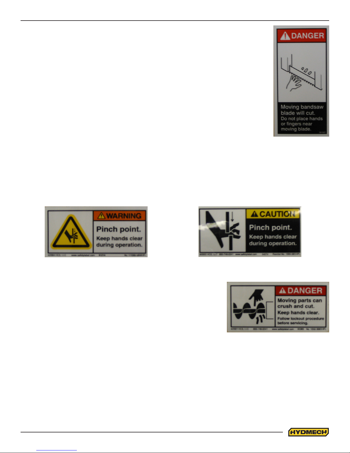
MOVING BANDSAW BLADE WILL CUT
Do NOT operate with guard removed.
Do NOT place hands or ngers near moving bandsaw blade.
For blade changing, always follow the proper Blade Changing Procedure, as given in
Section 3 of this manual.
PINCH POINT
Machine parts may move without warning, either because the machine is operating automatically, or because
another person initiates the motion. Keep hands clear of all labelled pinch points, whenever the machine is
running. Machine vises can exert great force and cause severe injury. Keep hands clear of vises and work piece
when vises are opened or closed. Be aware that vise closing or opening may result in potentially dangerous work
piece movement. Be aware also that the opening motion of a vise may create potential pinch points.
MOVING PARTS CAN CRUSH AND CUT
Keep hands clear of chip auger. Lock-out power in accordance with your
company’s lock-out procedures before attempting to clear a jam in the
chip auger.
Be aware that the chip auger may start unexpectedly, either because the
machine is operating automatically, or because another person initiates
the motion.
If the chip auger is stalled because of a jam, it may start without warning
when the jam is cleared, unless the machine power is locked out.
0.7
SECTION 1 - INSTALLATION
SAFETY CONSIDERATIONS
All safety precautions must be observed during installation, operation, or repair work on the V18 bandsaw machine.
Inspect the machine thoroughly before power hook-up. Pay special attention to the electrical and hydraulic systems to
ensure no damage was caused in shipping.
Power hook-up should be performed by qualied personnel.
If not performing properly, the machine should be stopped immediately and set-up, or repaired by a qualied person.
Stock must not be loaded while the blade is running and the V18 should not be operated unless all guards, covers, and
doors are in place and closed.
Long and heavy stock should be supported where it extends o the saw table.
The operator should keep a safe distance from all moving parts especially the blade and operating vises.
Long hair, loose clothing, or gloves, should not be worn while operating the V18.
The area around the machine should be kept clean and tidy.
The V18 machine should be used according to its specications.
The operator must wear eye protection.
No modications to the machine are allowed without Hyd-Mech’s prior approval. Any approved modications
shall be performed by trained personnel.
1.1
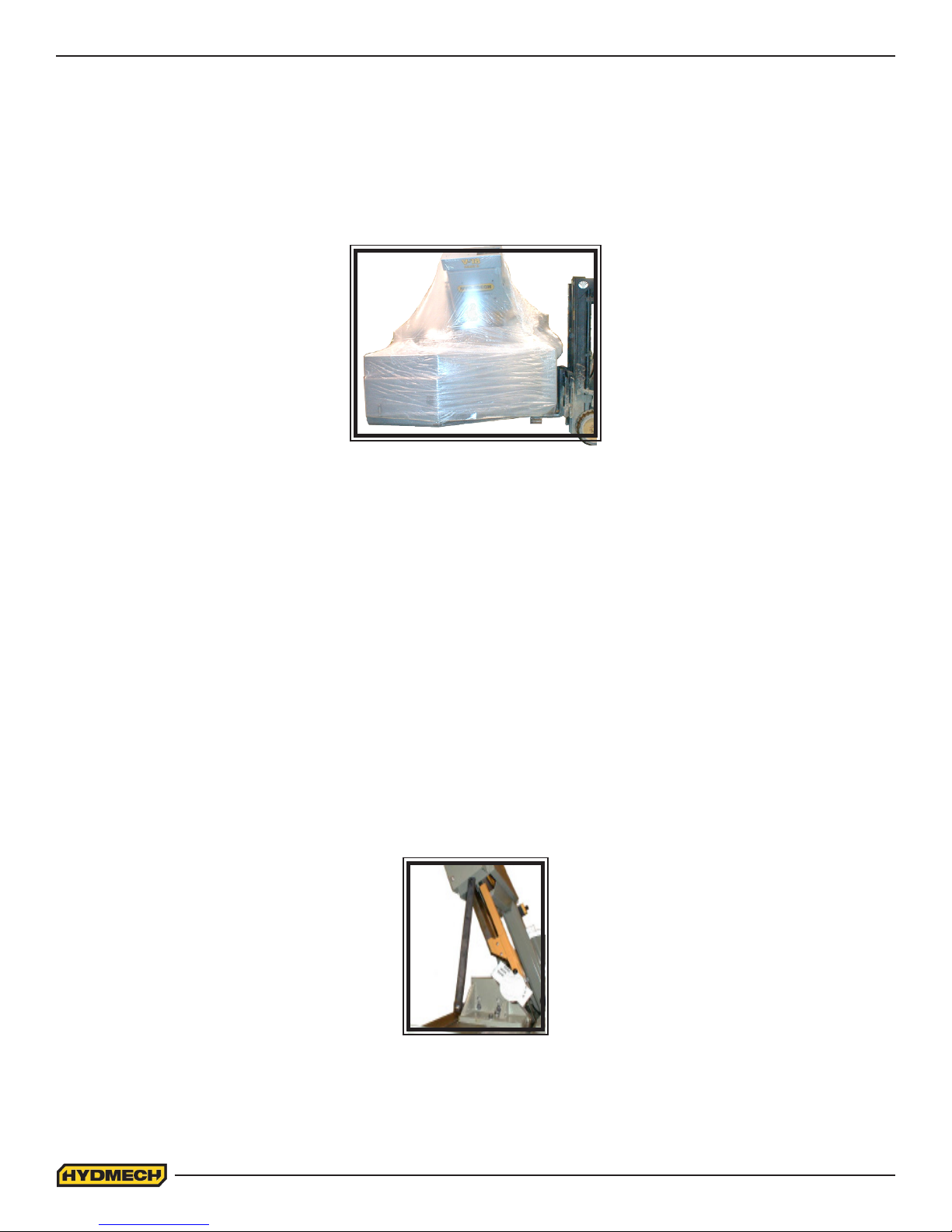
LIFTING AND SHIPPING
To lift a V18 bandsaw with a forklift, it must have a minimum capacity of 7500 LB. at 48” from the mast as well as 6’ forks.
Always lift the saw from the front as shown. The forks must not be under the electrical / hydraulic cabinet. The saw will
have 4 x 4 steel tubes under each leveling foot, these must be removed (save the bolts for anchoring) before positioning
the saw.
Lifting the V18 from the rear of
the machine.
REMOVING HEAD RESTRAINT
Before start-up remove the head support strut installed for shipping purposes to secure the head to the base. Replace the
two 5/16 NC countersunk screws which fasten the wearstrip down.
Head strut.
1.2
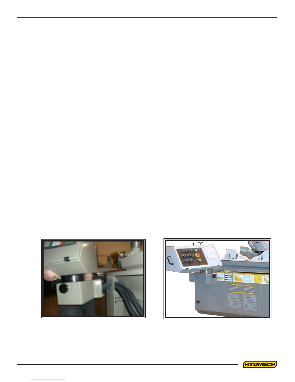
INSTALLATION OF THE CONTROL PANEL
The V18 comes equipped with an articulating control panel. This panel is normally removed and placed on the saw table
for shipping purposes. The control panel MUST BE REINSTALLED PRIOR TO MACHINE START UP. Take lifting precautions when installing the panel as it weights 150 LB.
To re-install the panel, follow these steps:
1 Remove all of the packing material.
2 Remove the base front cover from the machine to gain access to the interior of the base.
3 Lift the panel and move it into position as shown below. Insert the extra length of hoses and conduit back into the
front of the saw base enclosure.
4 Insert the four studs into their respective holes and fasten the panel using the supplied 3/8-16 UNC nuts and
washers.
5 Level the panel and fully tighten the nuts to lock assembly in place.
6 Place excess cord and hose length neatly inside the base enclosure and replace the base front cover.
WARNING! PANEL WEIGHT 150 LB.
Placing the control panel on to the front hole pattern.
The control panel installed.
1.3
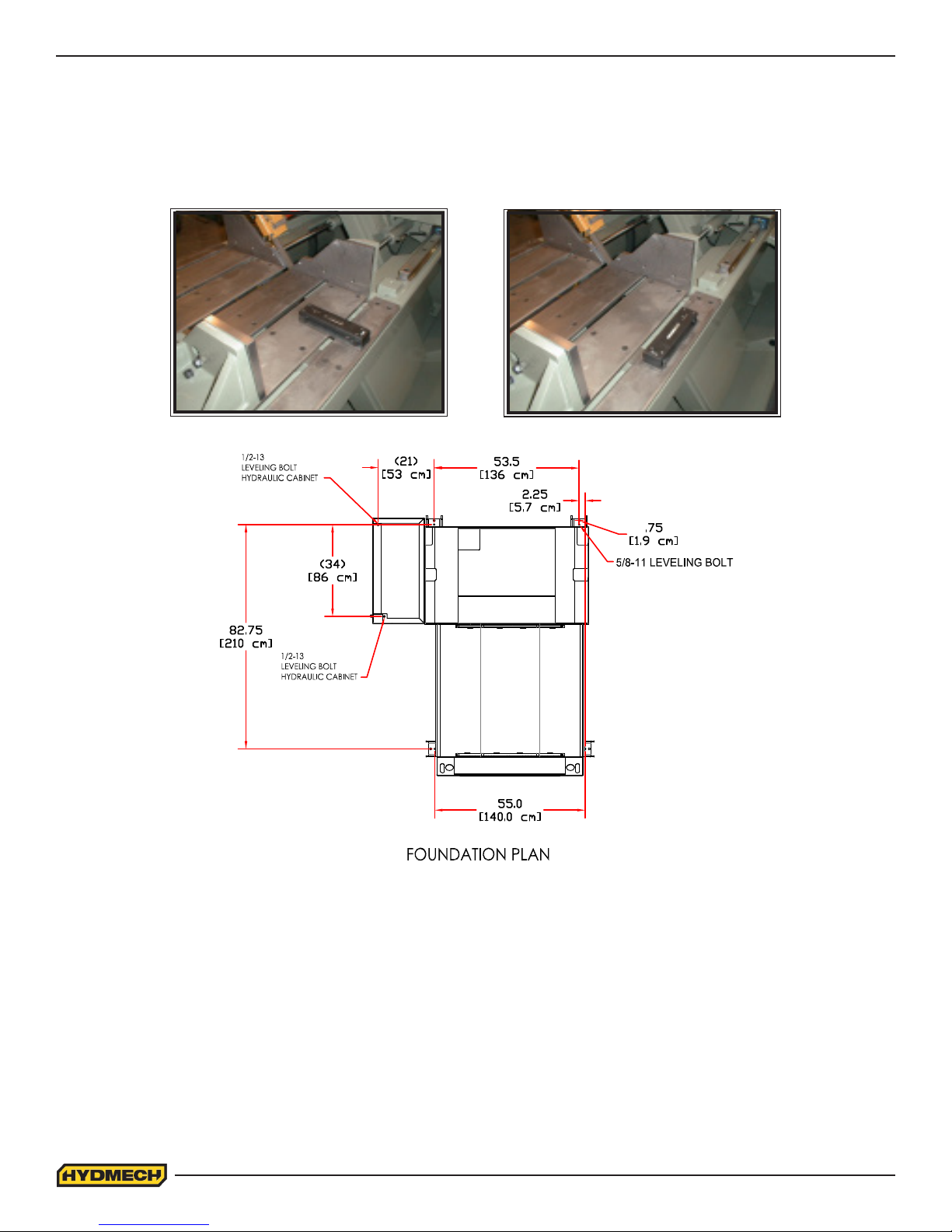
LEVELLING THE V18
It is important that the V18 be levelled and provision is made to secure the saw with concrete anchors to the oor.
* See foundation plan below *
Using a machinist’s level, level the saw from side to side and from front to back. When any additional conveyor(s) are being attached to the machine, they must be aligned to the table of the machine properly.
HYDRAULIC OIL
The V18 bandsaw is supplied with Texaco Rando HD46 oil. If it is necessary to change the oil to a dierent brand it is
good practice to empty the hydraulic tank using a pump. Fill the hydraulic tank approximately 1/3 full with the new brand
of oil and operate the saw through several cycles with maximum cylinder extension. Drain the hydraulic tank again and
then rell to capacity with the new brand.
CUTTING FLUID
As the V18 operates with an open reservoir to contain the cutting uid, no cutting uid can be shipped with the saw. There
are two main types of cutting uids available, oil based and synthetic. For oil based uids the dilution ratio is 1:10. One
part concentrate to ten parts water. For synthetic cutting uids dilution, if required, should be done to the specications as
recommended by the manufacturer.
1.4
WIRING CONNECTIONS
After the machine is levelled and anchored the necessary power hook-up needs to be performed. In order to provide safe
operation as well as to prevent potential damage to the machine, only qualied personnel should make the connections.
L1, L2, L3
BEFORE START-UP THE FOLLOWING TWO POINTS SHOULD BE
CHECKED
1. Signs of damage that may have occurred during shipping to
the electrical cables and the hydraulic hoses.
L1, L2, L3, G
(Cover in place)
2. The hydraulic oil level is between the upper and lower levels
on the gauge.
As supplied, the machine is set to run on three phase voltage as indicated on the serial plate and voltage label.
During the initial hook-up, it is very important to check that the phase
order is correct. This is indicated by the hydraulic system pressure gauge
registering a pressure rise and the blade running in a counter clockwise
direction. If the hydraulics do not register an immediate pressure rise,
SHUT THE HYDRAULICS OFF and change the phase order.
Power connection terminal
ATTENTION: Running the hydraulics “backwards” can damage the hydraulic pump!
Power connection to the machine is made to the L1, L2, L3 and ground terminals located inside the control panel as
shown in the photo.
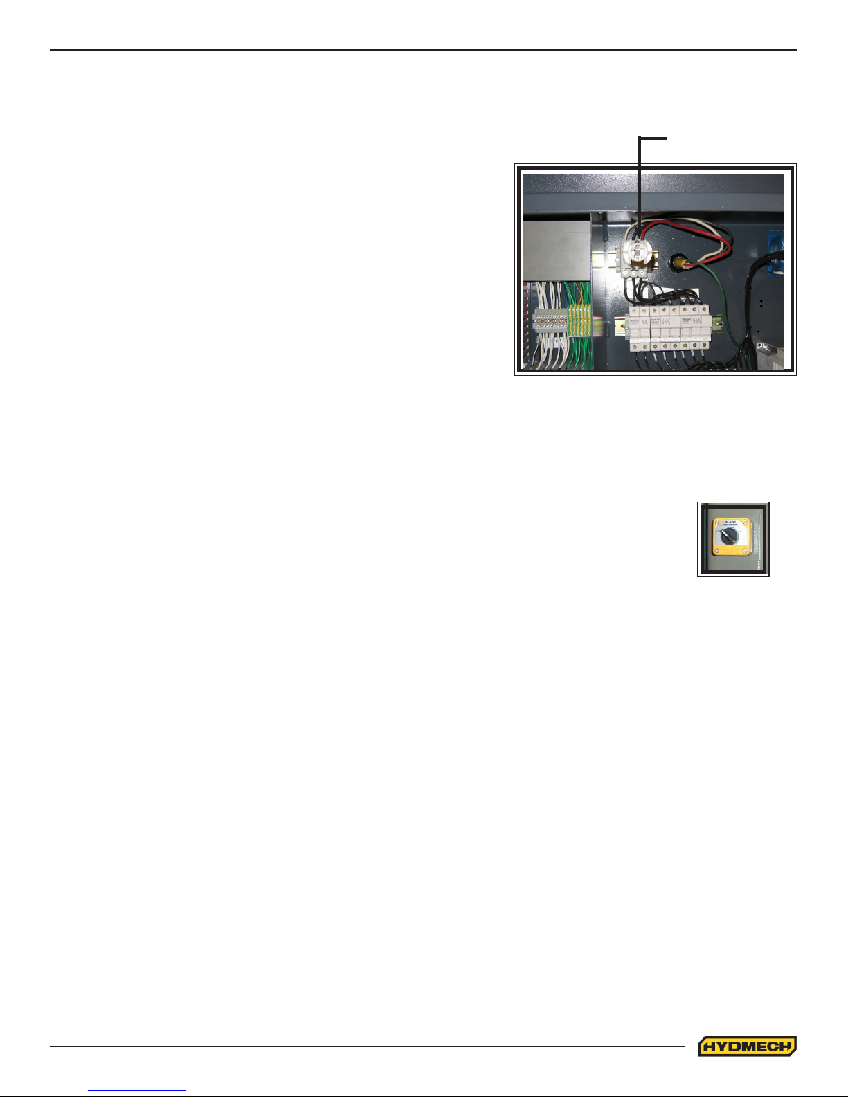
BLADE TENSION CHECK
When the machine is rst started, the blade position must be checked. Open the door at the top of the
head and see that the blade has not moved o of the wheel. It should not be overhanging the wheel
more than 1/4”. If it is consult “Blade Tracking” in Section 3 If it has stayed in it’s correct position, then
check that the blade tension switch is in the “+” position and close the door.
Blade tension
switch
EARTH GROUNDING PROCEDURE
1. The customer is to provide and install a ground rod approx. .60 (15mm) diameter, copper clad steel, to be driven
no less than 8’ (2.5m) into the ground, no more than 10’ (3m) away from control enclosure.
2. The ground rod is to be connected to customer’s in plant ground system. This connection shall be made directly
at the ground rod. (If applicable).
3. It is desirable that the overall resistance to ground measured at the ground rod does not exceed 3 ohms. Cus-
tomer is advised to consult local power company for further information on grounding.
4. The ground rod is to be connected to the ground terminal in the control enclosure using insulated, stranded 8
gauge copper wire.
5. An additional point to check is to ensure continuity of all ground within the control enclosure. Start with the main
power entrance ground terminal where the internal ground conductors should originate and then connect to, the
DIN terminal strip, control transformer, and the lid of control enclosure. Also, the PLC and Interface units should
have their own ground conductors connected to one of the main ground terminals.
6. A properly functioning ground system will:
- provide safety for personnel.
- ensure correct operation of electrical/electronic apparatus.
- prevent damage to electrical/electronic apparatus.
- help dissipate lightning strikes.
- divert stray radio frequency (RF) energy from electronic/control equipment.
1.5
 Loading...