


Dear Customer,
As a businessman you understand the necessity of keeping the cost of each step of production to an absolute
minimum without sacrificing quality. In the purchase of any new piece of equipment you are looking to increase your production and consequently reduce your cost, while maintaining or improving quality.
With these points clearly in mind we have designed the HYD-MECH S-25A. Our goal is to change stock cutoff from a "necessary evil" to a money making and time saving part of your operation.
Please use this manual to familiarize yourself and your employees on the proper operation and maintenance of
the S-25A.
We appreciate the confidence you have shown in our product and wish you every success in its use.
Sincerely,
HYD-MECH ENGINEERING LTD.
Stan Jasinski, P. Eng.,
President
HYD-MECH
P.O. BOX 1087 / WOODSTOCK, ONTARIO N4S 8P6 · PHONE (519) 539-6341 / FAX (519) 539-5126
PRINTED IN CANADA 1995

THIS PAGE INTENTIONALLY LEFT BLANK

TABLE OF CONTENTS
SECTION 1 - INSTALLATION
Safety......................................................................................................................................... 1.1
Lifting and Shipping.................................................................................................................... 1.1
Vise Cylinders............................................................................................................................. 1.2
Head Restraint Bar..................................................................................................................... 1.3
Leveling..................................................................................................................................... 1.3
Wiring Connections.................................................................................................................... 1.4
Hydraulic Oil and Cutting Fluid................................................................................................... 1.4
SECTION 2 - CONTROLS AND OPERATIONS
SUBSECTION 2A - The Control Console........................................................................................... 2.1
Start-up...................................................................................................................................... 2.1
S25 Manual Controls.................................................................................................................. 2.1
Shuttle Length Control................................................................................................................ 2.5
Conventional Length Control Set-up and Calibration................................................................... 2.5
S25 Automatic Controls (PLC 100)............................................................................................. 2.6
Blade Kerf......................................................................................................................... 2.6
PLC in Manual Mode ....................................................................................................... 2.7
PLC in Auto Mode - Single Job......................................................................................... 2.8
PLC in Auto Mode - Multi Job............................................................................................ 2.9
Important Notes With Respect To PLC Operation............................................................. 2.10
Interrupting the Auto Cycle...................................................................................... 2.10
Entering Blade Kerf................................................................................................. 2.11
Inch-Metric Input or Measuring................................................................................ 2.11
SUBSECTION 2B - Saw Cutting Controls........................................................................................... 2.12
Blade Basics............................................................................................................................... 2.12
Variable Speed Control............................................................................................................... 2.13
Hydraulic Feed Control............................................................................................................... 2.13
Using The Saw Cutting Parameters Door Chart........................................................................... 2.14
Step 1 Determine Effective MAterial Width....................................................................... 2.14
Step 2 Setting The Feed Force Limit................................................................................. 2.15
Step 3 Determine Optimum Blade Pitch............................................................................ 2.16
Step 4 Determine Optimum Blade Speed.......................................................................... 2.17
Step 5 Determine Feed Rate Setting................................................................................. 2.18
Cutting Control Set Up Examples................................................................................................ 2.20
SUBSECTION 2C - Mechanical Controls............................................................................................ 2.22
Head Up And Down Limit Setting................................................................................................ 2.22
Coolant Flow.............................................................................................................................. 2.23
Guide Arm Positioning................................................................................................................ 2.23
Blade Changing.......................................................................................................................... 2.24
SECTION 3 - MAINTENANCE AND TROUBLESHOOTING
Blade Brush................................................................................................................................ 3.1
Blade Guides.............................................................................................................................. 3.1
Lubrication............................................................................................................................... 3.2
Cleanliness................................................................................................................................. 3.3
Hydraulic Maintenance................................................................................................................ 3.3
Trouble Shooting......................................................................................................................... 3.4

SECTION 4 - ELECTRICAL SYSTEM
General Information.................................................................................................................... 4.1
Photos of Standard Electrical Components................................................................................. 4.1
Photos of Optional Electrical Components.................................................................................. 4.3
List of Electrical Components For An S-25A With the Optioanl PLC100.................................... 4.4
List of Electrical Components For A Standard S-25A.................................................................. 4.7
Standard Electrical Schematic S25-7-00-1.......................................................... 4.12
Standard Electrical Wiring Diagram S25-70-02 pg.1............................................... .... 4.13
Wiring Diagram S25-70-02 pg. 2 ................................................. 4.14
Wiring Diagram ( Contol Box) S25-70-02 pg.3.................................................... 4.15
Electrical Schematic (PLC Option) S25A-7-00-1A ..................................................... 4.16
Electrical Wiring Diagram PLC S25A-7-00-2A pg.1 ............................................. 4.17
Electical Wiring Diagram PLC (Control Box) S25A-7-00-2A2 pg.2 ........................................... 4.18
SECTION 5 - HYDRAULIC SYSTEM
General Information.................................................................................................................... 5.1
Parts List and Photos of Hydraulic Components.......................................................................... 5.1
Cylinder Components .................................................................................................................. 5.2
Positive Downfeed Valve Components ...................................................................................... 5.3
Hydraulic Schematic S25A-6-00-1 ...................................................... 5.4
Hydraulic Plumbing Diagram S25A-6-00-2 ....................................................... 5.5
Plumbing Diagram (VVP Option) S25A-6-00-2....................................................... 5.6
SECTION 6 - MECHANICAL ASSEMBLIES
Parts List and Photos:
Blade Guide Arm Assembly........................................................................................................ 6.1
Guide Arm Rack Assembly......................................................................................................... 6.2
Blade Brush Assembly................................................................................................................ 6.3
Drive Assembly.......................................................................................................................... 6.4
Idler Wheel Assembly................................................................................................................. 6.5
Vise Cylinder Mounting Assembly............................................................................................... 6.6
Front Table Assembly ................................................................................................................ 6.7
Gearbox Assembly.................................................................................................................... 6.8
Auxiliary Table Assembly............................................................................................................ 6.9
Shuttle Guide Assembly.............................................................................................................. 6.10
Infeed Conveyor assembly......................................................................................................... 6.11
Pivot Link Assembly.................................................................................................................. 6.12
Head Swing Assembly............................................................................................................... 6.13
Coolant System Assembly.......................................................................................................... 6.14
Outfeed Table Assembly............................................................................................................. 6.15
Length Control Assembly............................................................................................................ 6.16
SECTION 7 - OPTIONAL SAW EQUIPMENT
Overhead Bundling Attachment.................................................................................................. 7.1
Variable Vise Pressure................................................................................................................ 7.2
Blade Breakage Switch............................................................................................................... 7.3
Out of Stock Limit Switch............................................................................................................ 7.4
Remote Blade Speed Adjustment............................................................................................... 7.5
SECTION 8 - SPECIFICATIONS
Specification List........................................................................................................................ 8.1
Dimensional Drawings................................................................................................................ 8.2
SECTION 9 - WARRANTY
Warranty..................................................................................................................................... 9.1

SECTION 1 - INSTALLATION
SAFETY
All safety precautions must be observed during installation, operation, maintenance or repair work on the
S-25A bandsaw machine.
-Inspect the machine throughout before power hook-up. Special attention should be paid to electrical and
hydraulic systems keeping an eye out for any potential shipping damage.
-Power hook-up should be performed by qualified personnel.
-Machine should be used according to its specifications.
-Long hair, loose clothing, gloves, should not be worn while operating the machine.
-Stock must not be loaded while blade is running.
-Machine should not be operated unless all guards, covers and doors are in place and
closed.
1.1
-Long and heavy stock should be supported in where it extends off the saw table.
-Area around the machine should be kept clean and tidy.
-Operator should keep a safe distance from all moving parts especially the blade and vises.
-If not performing properly the machine should be stopped immediately and repaired by a qualified person.
-No modifications to the machine are allowed without Hyd-Mech’s prior approval. Any approved modifications
shall be performed by trained personnel.
LIFTING AND SHIPPING
To lift the S-25 bandsaw an overhead crane with a “T” shaped lifting harness should be used Fig. 1-1A and Fig.
1-2A. Hook the lifting harness to a chain shackle on the infeed base 'A' and to chain shackles on both sides of
the saw base 'B'. An experianced rigger should select the rigging based on the 7300 LB. weight of the saw.
WARNING: Under no circumstances should the lifting harness be pushing against any part of the saw.
B
B
A
Fig. 1-2AFig. 1-1A
1.2
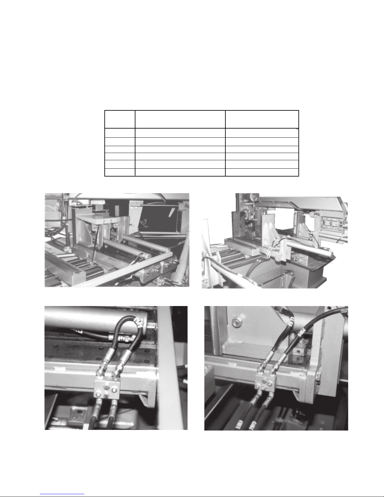
VISE CYLINDERS
To permit the S-25A to be shipped in a standard trailer, the three vise cylinders must be fully retracted, the
hydraulic hoses disconnected, and the mounting brackets unbolted from the infeed table Fig. 1-3. The cylinder
tube is then rotated around the cylinder rod so that the mounting bracket and tube are upside-down. This jaw
is now pushed completely toward the fixed jaw letting the bracket rest on the infeed table. Before the initial
start-up, reinstall the vise bracket and reconnect the vise cylinder hoses Fig. 1-4. TABLE 1 lists the hose
reconnections, Fig 1-5 shows one of the junction blocks as it appears when machine is shipped. Fig. 1-6
shows a junction block after the vise cylinder hoses have been reconnected.
HOSE # HOSE TO CYLINDER CONNECTING HOSE
CON NECTI ON AT JUNCTION BLOCK
34 ROD END (FRONT VISE) 32
33 PISTON END 31
24 ROD END (SHUTTLE VISE) 22
23 PISTON END 21
34C ROD END (AUX. VISE) 32 C
33C PISTON 31C
TABLE 1
Fig. 1-3 Vises disassembled for shipping.
Fig. 1-5 Junction block plumed for shipping.
Fig. 1-4 Reassembled vises.
Fig. 1-6 Vise cylinder plumed to junction block.
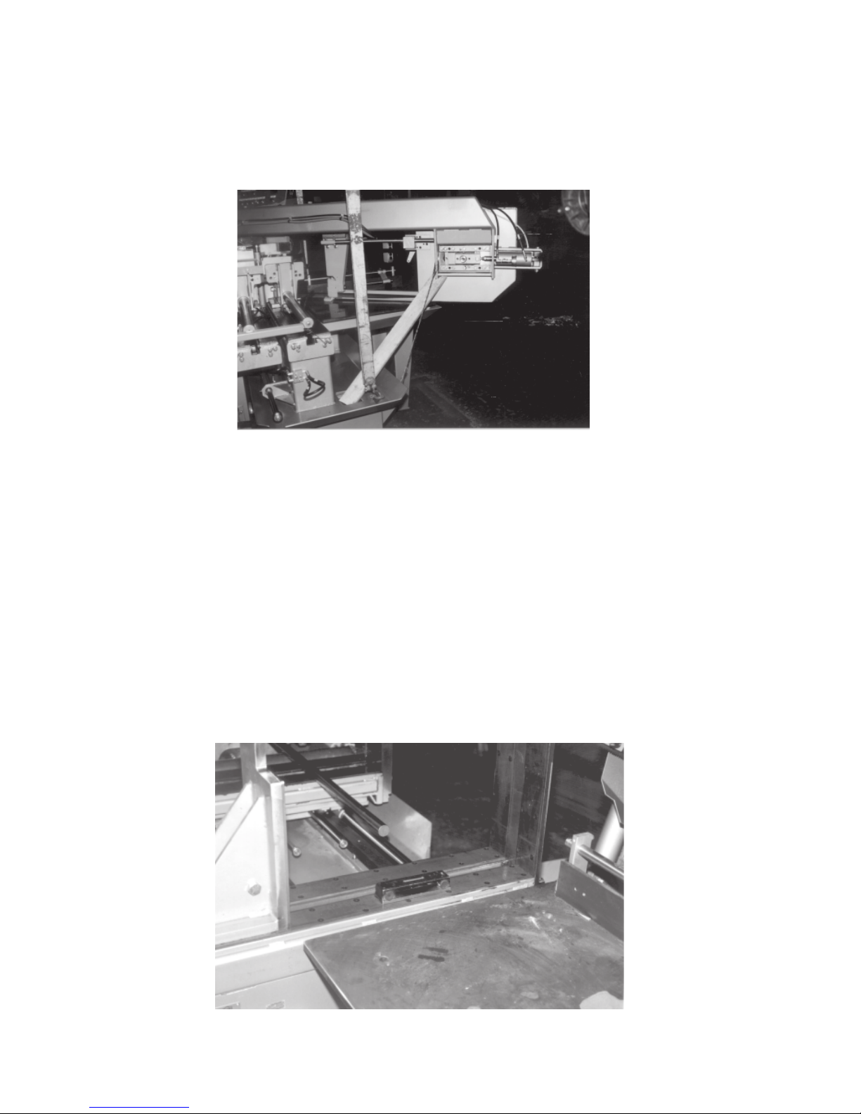
HEAD RESTRAINT BAR
The S-25A bandsaw is shipped with the head secured at the 45° position by a restraint bar and is wired down
to the base to ensure that the head can not move in any direction during shipping. After the saw has been lifted
into position, the head restraint bar must be removed along with the wire.
Fig. 1-7 Head restraint member and tie down wire.
1.3
LEVELLING
Machine location should be carefully selected. A flat concrete floor area should be chosen. It should have
enough free space surrounding the machine to enable free access for safe operation and maintenance.
Machine should be levelled in both directions ie. across its table and along its infeed conveyor especially when
machine is to be inserted into a large conveyor system.
Nine levelling screws are provided. Steel plates are to be placed under each screw to prevent their sinking into
the concrete floor. In cases when machine is to be anchored permanently, anchoring holes are provided. They
are located next to the levelling screws.
NOTE: In some cases levelling the saw infeed and auxiliary conveyors with a slight slope towards the blade is
recommended. This will prevent coolant from running down the raw stock. (This is especially true when cutting
tubing or bundles).
Fig. 1-8 Level the saw using a precision level.

1.4
WIRING CONNECTIONS
After the machine is levelled and anchored the necessary power hook-up needs to be performed. In order to
provide safe operation as well as to prevent potential damage to the machine, only qualified personnel should
make the connections.
BEFORE START-UP THE FOLLOWING TWO POINTS SHOULD BE CHECKED FOR
-signs of damage that may have occurred during shipping to the electrical cables and the hydraulic hoses.
-the hydraulic oil level is between the upper and lower lines on the level gauge (see SECTION 3 pg. 3.4).
As supplied, the machine is set to run on three phase voltage as indicated on the serial plate and voltage
label.
Power connection to the machine is made to L1, L2, L3 terminals at the junction block inside the control box
Fig.1-9. During the initial hook-up it is very important to check that the phase order is correct. This is indicated
by the hydraulic pressure gauge registering a pressure rise Fig. 1-10 and the blade running in a counter
clockwise direction. If the hydraulics do not register an immediate pressure rise, shut the hydraulics off and
change the phase order.
ATTENTION: Running the hydraulics "backwards" can damage the hydraulic pump.
L1, L2, L3
Terminals
Ground Clamp
Fig. 1-10 System pressure gauge.
Fig. 1-9 Electrical junction block.
HYDRAULIC OIL AND CUTTING FLUID
The S-25A bandsaw is supplied with Valvoline 150-46 hydraulic oil. If it is necessary to change the oil to a
different brand see the HYDRAULIC SECTION for an equivalent grade oil.
No cutting fluid is supplied with the machine. There are two types of coolant available:
- oil based; dilute 1:10 ratio
(one part concentrated coolant to 10 parts water)
- synthetic; dilute as recommended by the manufacturer.

SUB SECTION 2A - CONTROLS AND OPERATIONS
THE CONTROL CONSOLE
START-UP
The S-25A control console has been designed to simplify the operation of the saw, to give the operator the
ability to stop any function at any time, and to be able to control all the functions remotely. (See Fig. 2A-1)
We can not overstress the importance of familiarizing yourself with the controls of the S-25A prior to starting
the machine.
2.1
NOTE: WHEN STARTING THE S-25A FOR THE FIRST TIME
SWITCH IS IN IT'S
NEUTRAL
POSITION, THE BLADE IS RUNNING IN A
DIRECTION, AND THAT THE HYDRAULIC PRESSURE IS
pg. 3.4).
MAKE SURE
900 PSI
THAT THE MODE SELECTOR
COUNTER CLOCKWISE
± 25 PSI (see SECTION 3
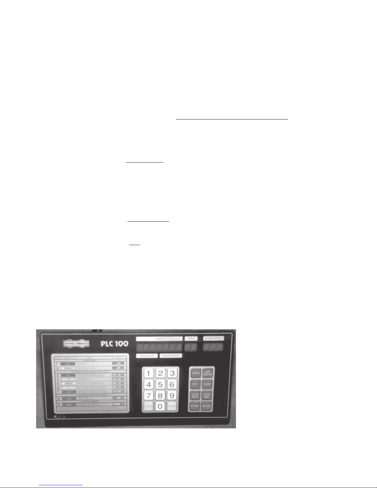
Fig. 2A-1 Standard S-25A operation control panel.
S-25A MANUAL CONTROLS
HYDR AULI C STAR T B UTTO N: Starts hydraulic pump motor and energizes the BLADE START BUTTON
BLADE MO TOR This button is only operative when the hydraulic system has been
STA RT BUTTO N: started. Momentarily depressing this button will start the blade
BLADE MOTOR Momentarily depressing this button will stop the blade motor.
STOP BUTTON:
and the MODE SWITCH.
The fixed vise will open or close according to its selector switch position.
The actions of all other functions are dependent upon the MODE SWITCH
position. (see MODE SWITCH)
motor.

2.2
EMERGENCY STOP
This button will stop both the hydraulic and blade motors and
BU TTO N: de-energizes the MODE SWITCH.
The head and shuttle motion will cease.
The vises will remain as they are, but if closed, they will gradually
lose gripping force. For this reason all long stock should be
supported so that in this eventuality, it will not fall.
HYDRAULIC AND B LADE Both of the drive motors are protected by individual overload relays.
MOTOR RES ET B UTTONS : If a motor draws excessive amperage, the corresponding relay will
open and the entire machine will shut down as if the EMERGENCY
STOP button had been pressed.
Depressing the corresponding RESET button will close the opened
contactor overload and allow the machine to be restarted.
MODE SWITCH: Has three positions, MANUAL, NEUTRAL, and AUTO
MANUAL: in manual all the following functions except the HEAD
SWING CONTROLS and the AUTO CYCLE DIAL,
are operative.
NEUTRAL:only the FIXED VISE SWITCH, the COOLANT SWITCH
and the HEAD SWING CONTROLS are operative.
AUTO: all of the functions are under the control of the AUTO
CYCLE DIAL, and the MANUAL CONTROL switches
are inoperative.
HEAD CONTR OL S WITCH: Inoperative unless MODE SWITCH is in MANUAL.
UP: the head will rise until it reaches the HEAD UP LIMIT SWITCH
SETTING.
HOLD: the head will remain stationary.
DOWN: the head will descend until it reaches the bottom. Descent
is controlled by the FEED RATE and FEED FORCE
controls.
INDE X F ORWA RD BUTTON : Button is inoperative except when MODE SWITCH is in MANUAL.
Depressing this button fully will cause the shuttle table to quickly
advance toward the saw table until the button is released or the
shuttle reaches the forward limit of travel.
Depressing this button partially will cause the shuttle table to
advance toward the saw table at a very slow rate until the button is
released or the shuttle reaches the forward limit of travel. This
control is intended to assist in the accurate positioning of heavy
pieces of stock.
INDEX REV ERSE BUT TON: Button is inoperative except when MODE SWITCH is in MANUAL.
Depressing this button fully will cause the shuttle table to quickly
retract away from the saw table until the button is released or the
shuttle reaches the rearward limit of travel.
Depressing this button partially will cause the shuttle table to retract
away from the saw table at a very slow rate until the button is
released or the shuttle reaches the rearward limit of travel. This
control is intended to assist in the accurate positioning of heavy
pieces of stock.
INDEX VISE SWIT CH: This switch is only operative when the MODE SWITCH is in
MANUAL. It operates in the same manner as the FIXED VISE
SWITCH but controls the vise mounted on the shuttle table.
2.3
FIXED VISE SWITCH:
This switch is operative as long as the machine is supplied with
power. Unlike the other function switches it is active when the
MODE SWITCH is in NEUTRAL. The FIXED VISE SWITCH
is wired this way to insure that the fixed vise will not release the
work piece when switching between AUTO and MANUAL, or if the
saw should shut down during a cut due to a motor overload. This
security is provided only if the FIXED VISE SWITCH is left in the
CLOSE position during automatic operation; the AUTO CYCLE
DIAL will open the front vise as required. The FIXED VISE
SWITCH should be turned to OPEN when shutting the saw down
for a prolonged period of time (i.e. overnight). When this switch
is in the CLOSE position, the fixed vise will stay closed even when
shutting the saw down with the EMERGENCY STOP button, but the
vise pressure will quickly drop off and it should not be relied upon
to hold unbalanced work pieces after shutdown.
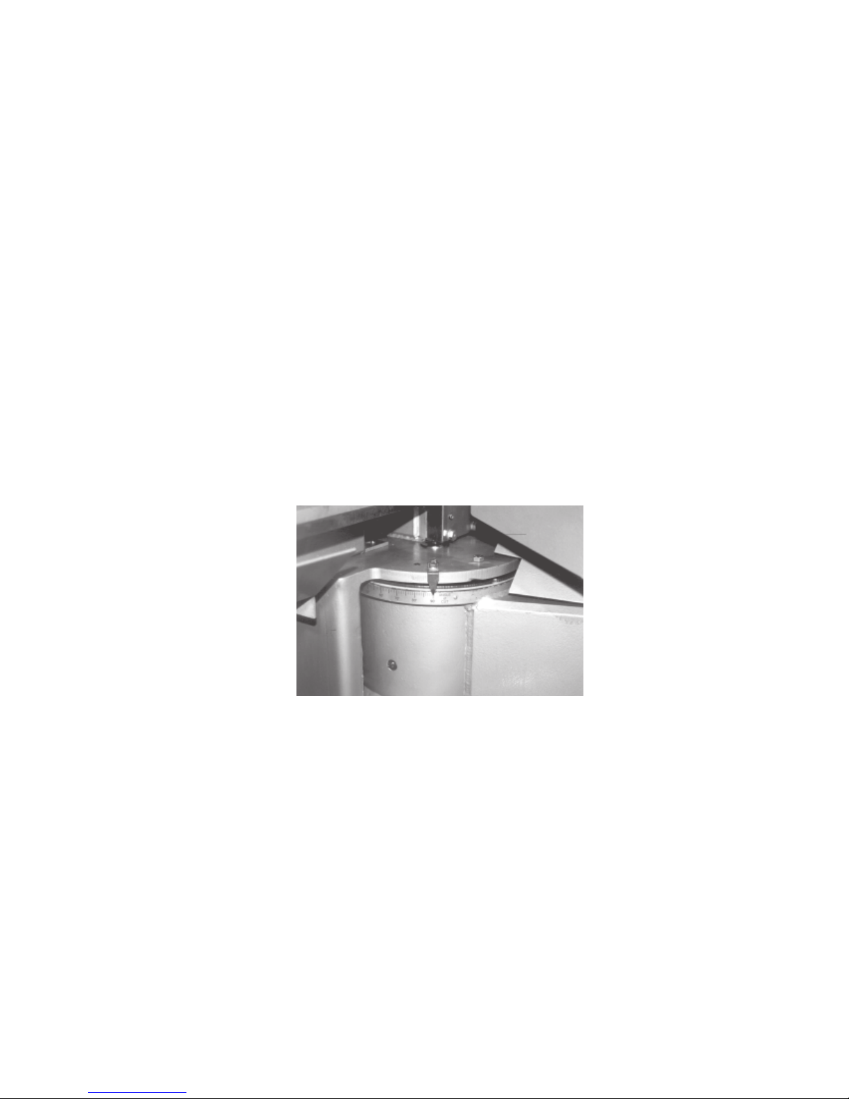
FAST SWING SWITCH: This switch is only operative when the MODE SWITCH is in the
NEUTRAL position.
Positioning this selector switch to 90° will swing the head fast towards the 90°
position. Likewise positioning this selector switch to 30° will swing the head
toward the 30° position. Leaving the switch on the lock position will restrain
the head from further angular motion. The angle change can be observed on
the angle scale located on the head swing drum Fig. 2A-2.
SLOW SWING SWITCH: Operates in the same manner as the FAST SWING SWITCH except it
swings the head at a slower rate making fine adjustment easier.
COOL AN T SWITC H: Has three positions ON, WASH, and OFF
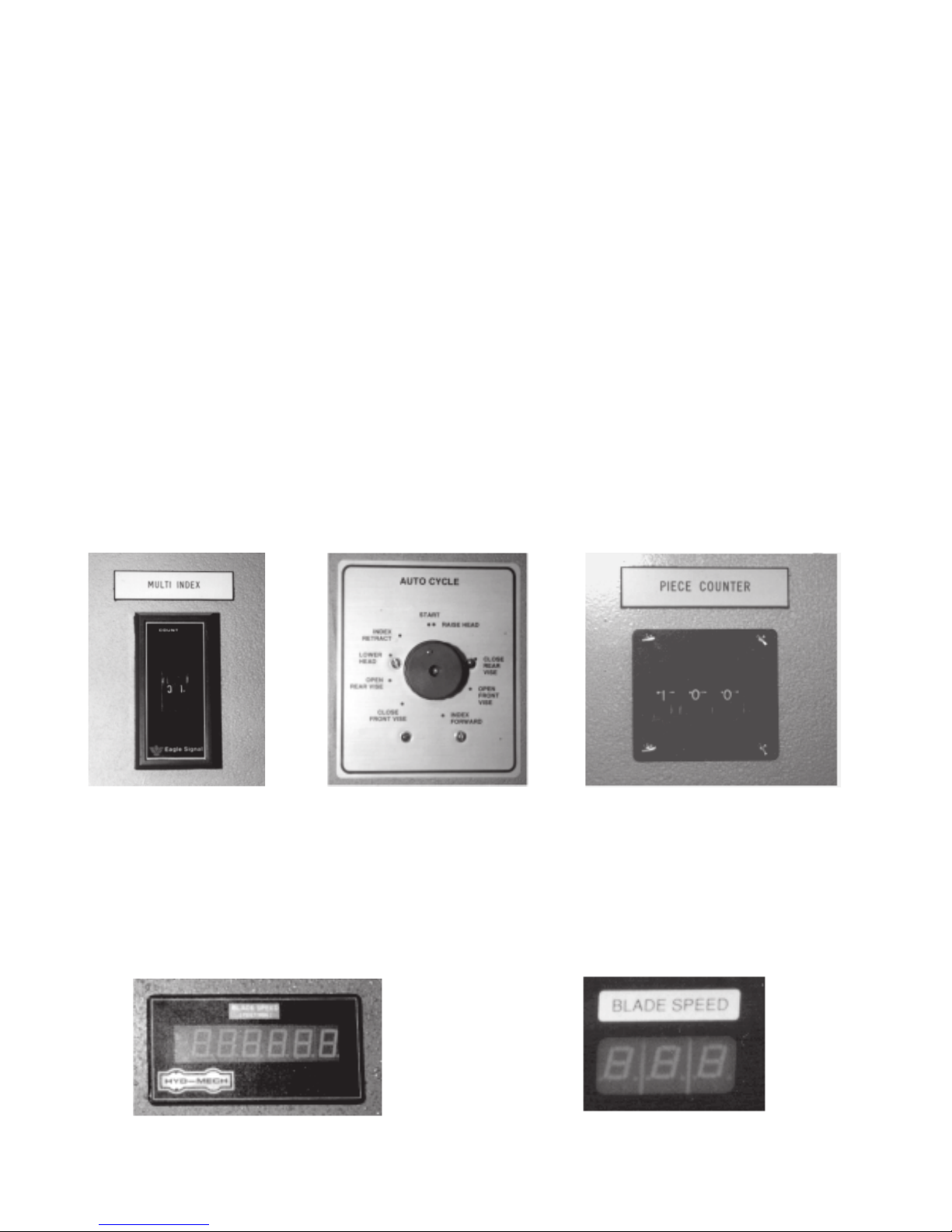
MUL TI I NDE X CO UNT ER:The counter is operative only in the AUTO MODE. The number on
Fig. 2A-2 Angle scale.
ON: the coolant flows only when the head descends
WASH: coolant flows any time the machine is under power, permitting
wash-down with the hand line without running the machine
OFF: no coolant flow
the manually set thumb wheel display, controls the number of
shuttles made by the shuttle table between each saw cut Fig 2A-3. If the
setting is changed during the shuttling portion of the AUTO CYCLE,
the new setting will not be accepted until after the current cutting
cycle.
2.4
AUTO CYCLE DIAL:
This knob rotates in a clockwise direction when the saw is running and the
MODE SWITCH is in AUTO Fig. 2A-4.
As it rotates it sends out control commands indicated on the dial. Whenever
the head or shuttle motion is initiated, the dial will stop and wait for the
motion to reach the end of its travel, and then it will resume its rotation.
It is recommended that the AUTO MODE always be initiated with the AUTO
CYCLE DIAL in the START position. This will result in the fixed vise closing,
the index vise opening, the head lowering (unless it is already down), and
the shuttle table retracting (unless it is already retracted). The head will then
rise to the limit set by the HEAD UP LIMIT SWITCH and the cycle will
proceed in order, as on the dial. When manually positioning the AUTO
CYCLE DIAL, it should always be turned in the clockwise direction.
NEVER TURN THE AUTO CYCLE DIAL COUNTER CLOCKWISE.
PIECE COUNTER: The counter is operative in both AUTO and MANUAL Fig. 2A-5. It is manually
set to the number of cuts desired and counts down to zero at which point it
turns the saw off. If the counter is set at zero it will not permit the saw to be
started. If in the MANUAL MODE it is desired to have the saw shut down at
the end of the cut, the PIECE COUNTER must be set to 1 (one) before the
cut. The counter counts one half count when the head down signal begins and
the other half count when the head down signal ends. Thus, if the AUTO
CYCLE is interrupted during cutting, a false count will be recorded. In this
event simply push the PIECE COUNTER back up one count.
Fig. 2A-3 Multi index
counter.
BLADE SPEED SWITCH: This optional switch controls the blade speed which can be infinitely adjusted
(OPTIONAL)
between 75 and 400 SFPM. The blade speed change can be observed on the
blade speed digital display, located on the front control panel (Fig. 2A-6). On
machines quipped with the optional PLC 100 controller the blade speed is
displayed in the blade speed window located on the PLC controller (Fig. 2A-
7). Switch is active only when blade is running.
Fig. 2A-6 Blase speed digital readout.
Fig 2A-4 Auto cycle dial. Fig. 2A-5 Piece counter.
Fig. 2A-7 Blade speed display
window on the PLC 100.

SHUTTLE LENGTH CONTROL
To adjust for desired stock for a production run,as shown in Fig. 2A-8, move the Adjusting block 'A' to the
desired position along the scale. Fine adjustments can be made using the micrometer 'B'. The zero point on
the micrometer is .250 inch. This gives you 1/4" in and 1/4" out for fine adjustment.
A
B
Fig. 2A-8 Length control block.
CONVENTIONAL LENGTH CONTROL SET-UP AND CALIBRATION
2.5
The calibration makes no allowance for kerf loss and this must be added by the operator. Although blade
thickness is standard with relation to blade size, blade kerf may vary due to different pitch or manufacturer. We
recommend that you measure the kerf of the blade which you are using by making a cut into a solid piece of
steel and measuring the width of the cut. In the following examples we will use a blade kerf of .080". The
procedure for setting and calibrating the conventional length control is as follows:
To obtain a desired piece length add the kerf allowance. If the resulting length is less then 40", fully advance
the shuttle and set the adjusting block pointer to the resulting length. Set the Multi-Index Counter to "1".
If the resulting length is greater than 40", divide it by the smallest number which will result in a dividend less
than 40". Fully advance the shuttle and set the adjusting block pointer to the resulting dividend. Set the MULTI
INDEX COUNTER to the divisor.
Example 1
Desired piece length 9 3/4"
+ Kerf aprox. 1/16"
= Total shuttle required 9 13/16"
The result is less than 40". Set the adjusting block pointer to 9 13/16" and the MULTI INDEX COUNTER to "1".
Example 2
Desired piece length 73 3/8"
+ Kerf 1/16"
= Total shuttle required 73 7/16"
The result is greater than 40". We must divide by 2 in order to get a dividend less than 40 inches.
Set the adjusting block to 36 23/32" and the MULTI INDEX COUNTER to "2".
73.4375
= 36.719
2
2.6
It is wise to make a trial cut in order to check the accuracy of the length setting. Start by being certain that the
head up limit switch is correctly set up for the work piece. Using the manual mode raise the head fully and
advance the stock about 1/16" - 1/8" beyond the blade for a trim cut. Make the required trim cut.
Set the PIECE COUNTER to "2" and the AUTO CYCLE KNOB to "START". Start the blade and switch the
MODE SWITCH to "AUTO". The stock will advance and a cut will be made resulting in a trial piece.
Check the length of this piece. If it is not accurate enough, use the micrometer head to zero in on exactly the
length you require. The general procedure for using the micrometer length adjustment is as follows:
NEW MICRO SETTING = OLD MICRO SETTING + (DESIRED LENGTH - ACTUAL LENGTH)
NUMBER OF INDEXES
If in example 1, the resulting piece was 9.775 inches rather than the disired 9.750" then:
NEW MICRO SETTING = .250 + 9.750 - 9.775
1
= .250 + (-.025)
= .225
If in example 2, the resulting piece was 83.313" rather than the required 83.275" then:
NEW MICRO SETTING = .250 + 83.375 - 83.313
3
= .250 + .062
3
= .271
Increasing the micrometer setting increases the part length, while decreasing the micrometer setting decreases the part length.
NOTE: Remember to reset the micrometer to exactly midscale at the end of each run.
S-25A AUTOMATIC CONTROLS
BLADE KERF
Although blade thickness is standard with respect to blade size, blade
kerf may vary due to different pitch
or manufacturer. We recommend
that you measure the kerf of the
blade which you are using by making a cut into a solid piece of steel
and measuring the width of the cut.
In the following examples we will
use a blade kerf of .080".
Fig 2A-9 Optional PLC 100 programmable controler.

2.12
SUBSECTION 2B - SAW CUTTING CONTROLS
This section has been prepared to give the operator the ability to set up the saw for most cutting situations.
The saw is equipped with variable speed control and hydraulic feed control, as well as an extensive door chart
to guide the operator in the correct setting of these controls.
BLADE BASICS
Technology is rapidly changing all aspects of production machining. Metal cut-off is no exception. The
advances made in the bandsaw blade industry have definitely brought down the cost per cut, despite the three
fold higher price of high technology blades.
Variable pitch, bi-metal blades (like the 2/3 or 4/6 bi-metal blade supplied with the S-25A series saws) last
much longer, cut faster, and more accurately than conventional carbon steel blades.
In order to take advantage of the superiority of bi-metal blades, it is critical to properly “break-in” a new blade.
This is accomplished by taking two or three cuts through solid four or five inch diameter mild steel at an
extremely slow feed rate. (utilizing a very slow blade speed is recommended)
These two or three slow cuts sufficiently lap (polish) the new blade so that it does not snag the material being
cut. Proper break-in will alleviate blade vibration, improve surface finish, accuracy, and blade life.
After “break-in” the following six points must be closely monitored to ensure long blade life:
1. Proper blade tension should be maintained. (see SECTION 3 pg. 3.4 BLADE TENSION)
2. Generous coolant application is essential with almost all materials. A high quality and well mixed
coolant will many times extend blade life, and also increase cutting rate quality. On those materials
where c oolant is undes irable forcutting, a slight coolant flow or periodic oiling of the blade is necessary
to prevent the blade from being scored by the carbide guides.
3. The stock being cut must be securely clamped in the vises.
4. The proper feed force must be chosen.
5. The proper blade speed must be selected.
6. The proper feed rate must be applied.
2.13
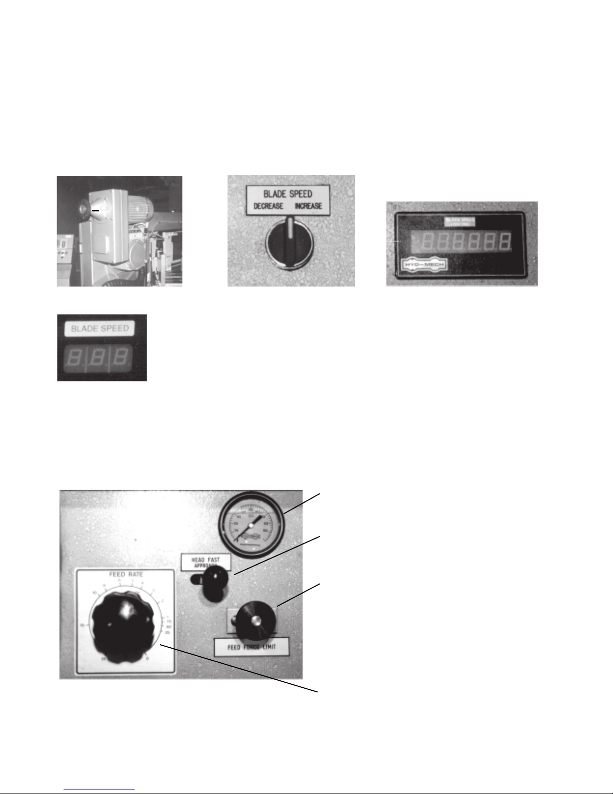
VARIABLE SPEED CONTROL
Blade speed can be adjusted infinitely between 75 and 400 SFPM (Surface Feet/Minute). Adjustment should
be made only when the blade is running. Clockwise rotation of handwheel “A” (Fig. 2B-1) increases the blade
speed while counter clockwise rotation decreases the blade speed. Blade speed is displayed on an indicator
located in the adjustment hand wheel. On machines equipped with the optional remote blade speed adjustment, adjustment is made using the BLADE SPEED selector switch Fig 2B-2 located on the control panel.
Blade speed is displayed on the digital blade speed display Fig. 2B-3 or on the blade speed display window
located on the optional PLC 100 controller Fig. 2B-4.
A
Fig. 2B-1 Blade speed adjustment.
Fig. 2B-2 Blade speed selector
switch.
Fig. 2B-3 Digital blade speed
display.
Fig. 2B-4 Blade speed display window.
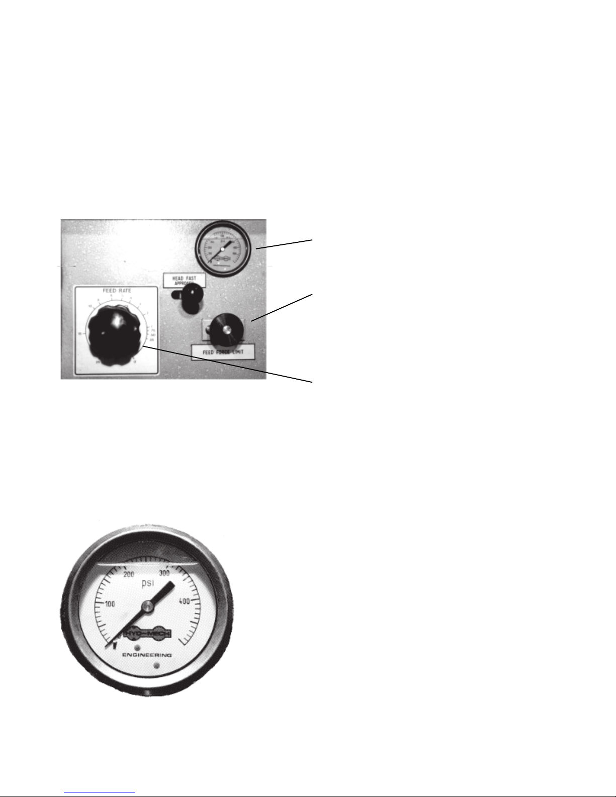
HYDRAULIC FEED CONTROL
The hydraulic feed control is located on the control panel below the electrical control console. These controls
allow independent control of Feed Force and Feed Rate. See Fig. 2B-5.
Feed Force Gauge
Fast Approach Lever
Depress for fast head descent
Feed Force Knob
Used to set Feed Force Limit
(clockwise rotation to increse
and counter clockwise rotation
to decrease).
Fig 2B-5 Hydraulic feed control.
Feed Rate Knob with feed rate scale
(calibrated in inches/minute)
Used to set Feed Rate (counter clockwise
rotation to increase and clockwise
rotation to decrease
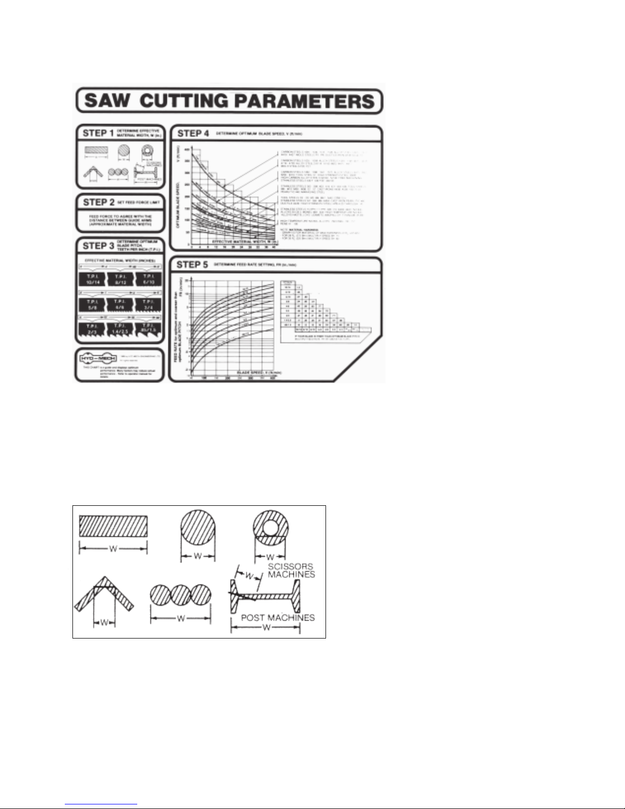
USING THE SAW CUTTING PARAMETERS ON CHART
2.14
A full size chart is mounted on the
panel. The chart contains five steps for
the operator to follow in order to achieve
optimum performance of the saw.
Fig. 2B-6 Saw cutting parameter door chart.
As Example #1 we will use the CHART to set up the saw, for cutting 8" Diameter, 1045 Carbon Steel.
STEP 1
DETERMINE EFFECTIVE MATERIAL WIDTH, W (in.)
Effective material width, W (in.) for most
common shapes of materials, is the widest
solid part of the material to be in contact with
blade during cutting. For simple shapes, as
illustrated on the chart, this can be diractly
measured. For bundles of tubes and
structuals, measuring the effective width is
difficult. For those cases effective width is
60% to 75% of the actual material width.
Fig. 2B-4
NOTE:
2.15
Both effective material width and guide arm width are used in setting the saw. Guide arm width is the distance
between the guide arms and is used in STEP 2. Effective material width, as determined here in STEP 1, can be
thought of as the average width of material “seen” by each tooth, and it is used in STEP 3 and 4.
In Example #1, for an 8" diameter solid, effective material width is 8".
STEP 2
SET FEED FORCE LIMIT
The Feed Force Limit is the maximum amount of force with which the head is allowed to push the blade into the
workpiece. The controls for setting the Feed Force Limit consist of:
Feed Force Gauge
Feed Force Knob
Feed Rate Knob
To set FEED
Fig. 2B-5 Hydraulic feed control.
FORCE LIMIT:
- With the Mode Switch in “manual” position, move the head fully down.
- After the head is down, open the feed rate valve, depress the yellow FEED
FORCE SETTING button and adjust the FEED FORCE.
Example #1
Set the feed force at 250-300 psi. This will protect
the blade from buckling. This amount of feed force
will also prevent the blade from cutting out of square.
If the cuts obtained are not square and the blade is
not at fault, reduce the feed force pressure. Generally a higher feed force can be used when cutting
solids. When cutting structuals or bundles a lower
feed force should be used.
Fig. 2B-6 Feed Force pressure.
2.16
SIGNIFICANCE OF GAUGE READING:
With the head down and yellow button depressed the (FEED FORCE “set” on manual control panel) FEED
FORCE gauge indicates the setting of the FEED FORCE LIMIT. During cutting the gauge shows the actual
force being applied by the blade to the workpiece.
In typical cutting situations, the needle on the gauge will rise toward the preset FEED FORCE LIMIT and
stabilize, usually at a lower level. If the material being cut is very hard or wide, the needle may rise all the way
to the preset FEED FORCE LIMIT, which it will not exceed.
When cutting soft materials and or narrow cross sections, the gauge reaging may be low, but the FEED RATE
will be maintained. Any changes during cutting, such as, material hardness or material cross section will
influence the gauge readings. Therefore, in some cutting situations the gauge reading may rise and fall. A very
low gauge reading is uaully observed when the blade is approaching the material to be cut, but not yeyt cutting.
STEP 3
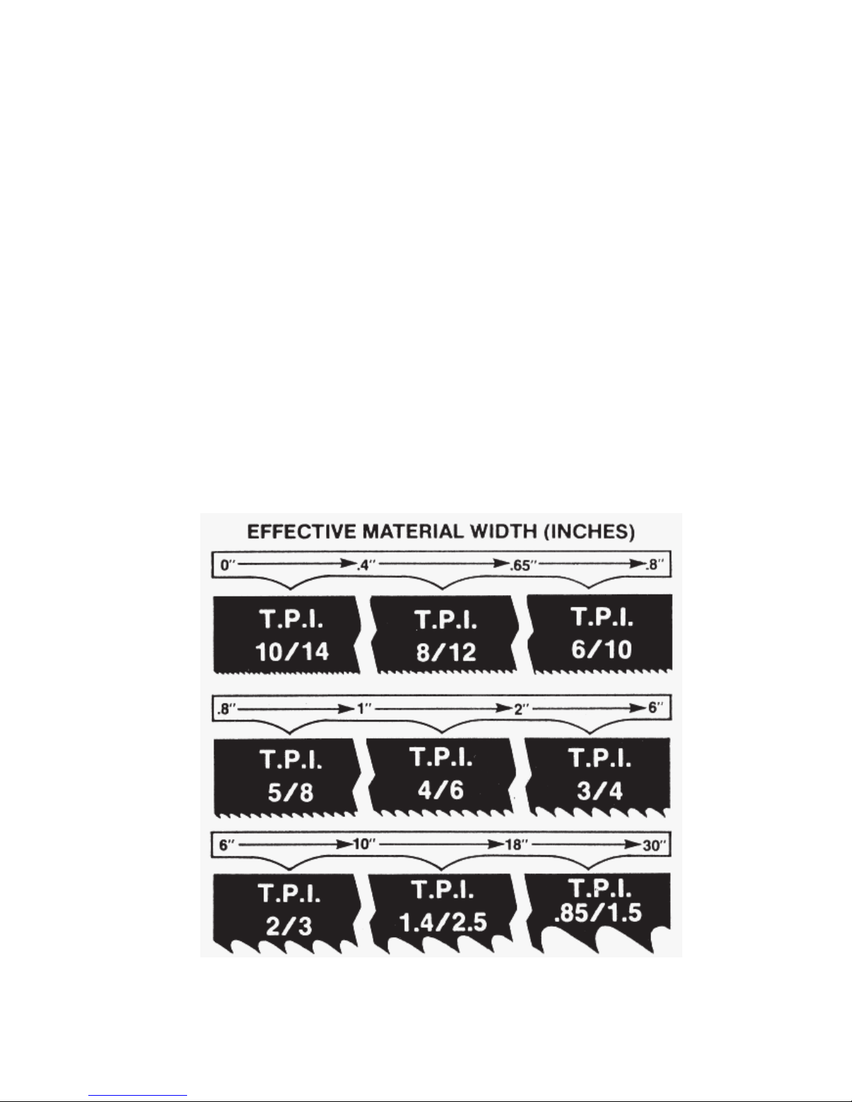
DETERMINE OPTIMUM BLADE PITCH, TEETH PER INCH (T.P.I)
Selecting a blade with proper tooth pitch is important in order to acheive optimal cutting rates and good blade
life.
For cutting narrow or thin wall structual materials a fine blade with many teeth per inch (T.P.I) is recommended.
For wide materials a blade with a coarse pitch should be used (see Fig 2B-7 below).
It is impractical to change the blade to the proper pitch every time a different width of material is cut and it is not
Fig. 2B-7 Optimum blabe pitch, teeth per inch (T.P.I.) for effective material
width, W (in.).
2.17
necessary, but remember that the optimum blade will cut most efficiently. Too fine a blade must be fed slower
on wide material because the small gullets between the teeth will get packed with chips before they get across
and out of the cut. Too coarse a blade must be fed slower because it has fewer teeth cutting and there is a limit
to the depth of a cut taken by each tooth. Allowance for the use of a non-optimum blade is made in STEP 5.
In our Example #1, for an effective material width of 8" the optimum blade has 2/3 teeth per inch.
STEP 4
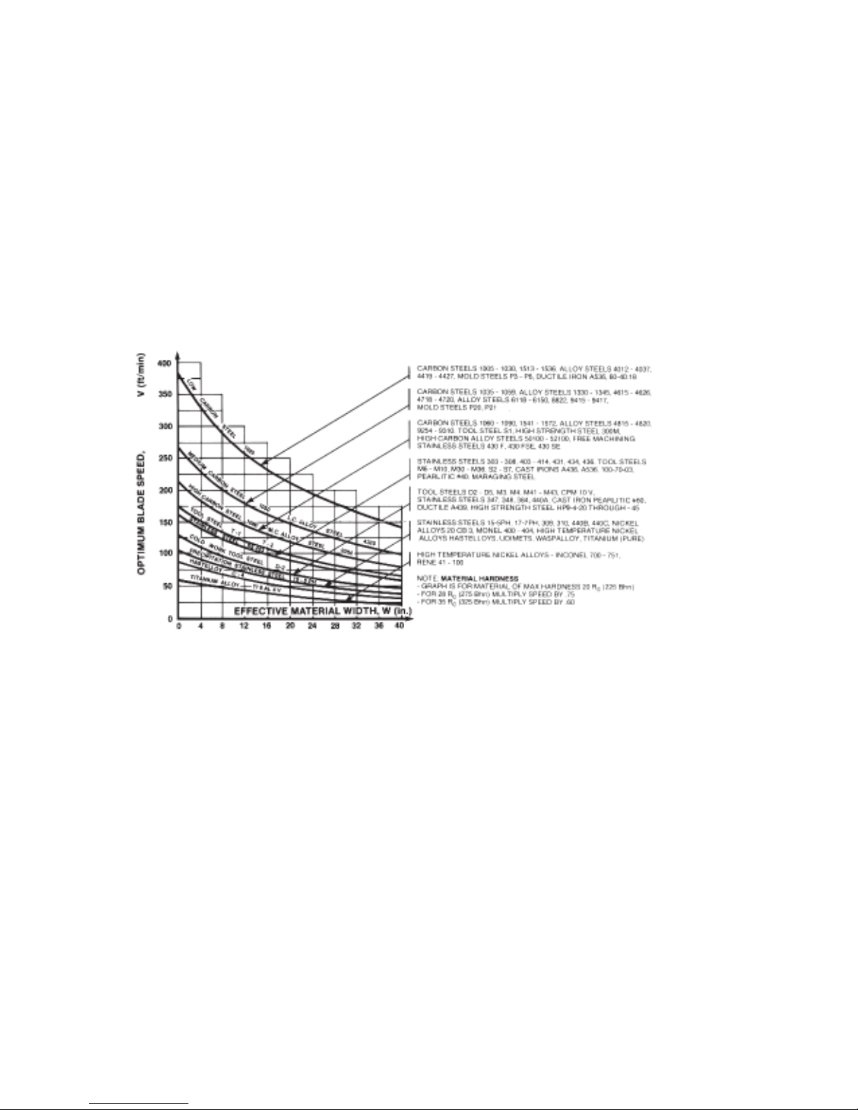
DETERMINE OPTIMUM BLADE SPEED, V (ft/min)
The relationship between optimum blade speed and effective material width for various materials is represented
on the graph Fig. 2B-8.
The graph shows that as effective material width gets wider or as material gets harder, lower blade speeds are
recomended. If material is narrower or soft, higher blades speeds should be selected.
Fig. 2B-8 Optimum blade speed curves.
In Example #1 8" Dia, 1045 Medium Carbon Steel solid bar is to be cut.
- On the graph above find the Medium Carbon Steel Curve which represents the optimum blade speeds for
1045 Carbon Steel.
- On the horizontal axis (effective material width axis) find number 8 which represent effective material width
of an 8" diameter solid.
- Find the point where a vertical line from 8" intersects the Medium Carbon Steel Curve.
- From this intersection point run horizontally left to the vertical axis (optimum blade speed axis) and find the
point marked “200”.
- Thus, for 8"diameter, 1045 Carbon Steel solid bar 200 ft/min is the optimum blade speed.
NOTE: Higher than optimum blade speed will cause rapid blade dulling. Lower than optimum blade speeds
reduce cutting rates proportionately and do not result in significantly longer blade life except where there is a
vibration problem. If the blade vibrates appreciably at optimum speed as most often occurs with structuals and
bundles, a lower blade speed may reduce vibration and prevent premature blade failure.
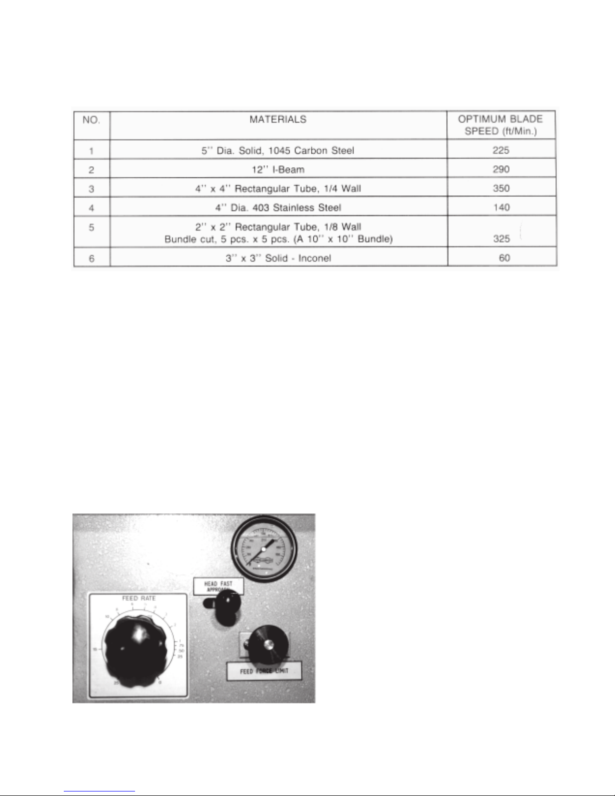
The table below shows a few examples of optimum blade speed for different materials.
TABLE 2B-1
NOTE: About Material Hardness
The Graph - Step 4, Fig 2B-8, illustrates blade speed curves for material hardness 20 Rc (225 Bhn) or lower.
If the material is harder , use multipliers from the NOTE (near the bottom) of the Graph.
2.18
For example, if the 5 diameter, 1045 Carbon Steel material, from the table above, had been hardened to 35 Rc
(325 Bhn) then we must multiply the blade speed of 225 ft/min by .60.
Thus 225 ft/min x .60 = 135 ft/min. (This is the optimum blade speed for 5" diameter, 1045 Carbon Steel, 35 Rc
hard).
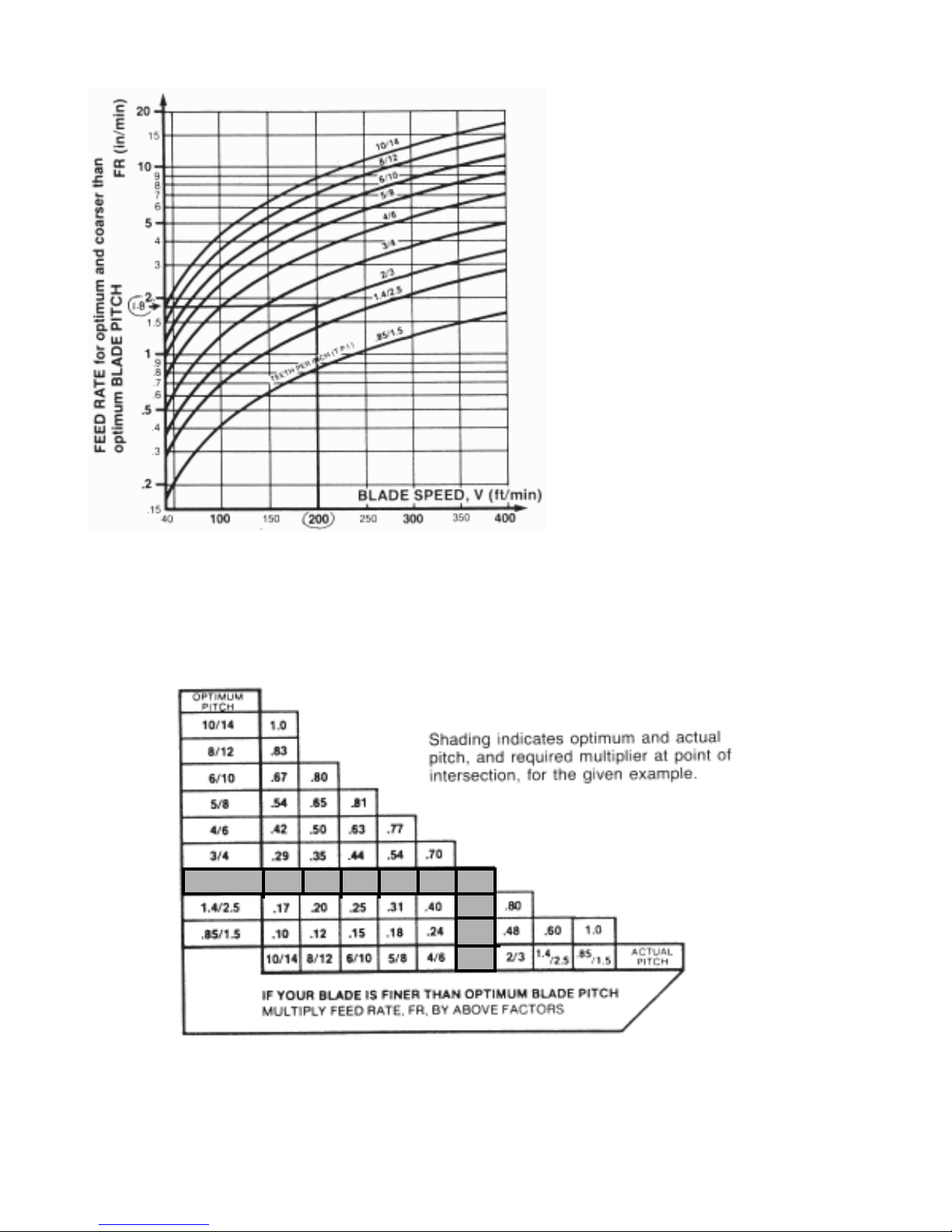
STEP 5
DETERMINE FEED RATE SETTING, FR (in/min)
FEED RATE is the vertical speed at which the blade descends through the workpiece.
FEED RATE Knob controls FEED RATE of the
blade in the range 0 to 25 in/min.
The FEED RATE should be adjusted only in one
direction (from “0” to required value). If you go too
far, go back to “0” and come back up.
To set FEED RATE for particular cutting situations
use the Graph, Fig 2B-10, which represents the
relationship between FEED RATE, blade speed
and blade pitch.
Fig. 2B-9 Hydraulic feed control.
2.19
` For Example #1, it is known from Step
3 that otimum blade pitch is 2/3, and
from Step 4 that blade speed ,200 ft/
min. From the graph, Fig. 2B-10 the
FEED RATE is determined in the
following way:
- On the horizontal axis (blade speed
axis), find 200 ft/min.
- Find the point where a vertical line
from 200 ft/min would intersect the
2/3 blade pitch curve.
- From this intersection point run
horizontally left to the vertical (FEED
RATE) axis, to arrive at 1.8 in/min
FEED RATE. Thus 1.8 in/min is the
FEED RATE for cutting 8" diameter,
1045 Carbon Steel when the optimum
2/3 pitch blade is used.
Fig. 2B-10
If the machine is fitted with a blade coarser than optimum (eg. 1.4/2.5 TPI) we can still use the graph, but we go
to the 1.4/2.5 curve. As a result we find that the FEED RATE is decresed to 1.3 in/min for this blade.
If however, the machine is fitted with a finer than optimum blade (eg. 3/4 TPI) we use the graph for the optimum
blade as before, and then use a multiplier given by the table 2B-2.
2/3 .21 .25 .31 .50.38 .71
.57
.34
3/4
TABLE 2B-2
As a result we find that we must decrease our FEED RATE of 1.8 in/min by a factor of .71. In this case we
should use FEED RATE of 1.8 in/min x .71 = 1.3 in/min.

CUTTING CONTROL SET UP EXAMPLES
FOR EXAMPLES #2 AND #3 PLEASE GO TO THE SAW AND FOLLOW STEPS 1-5 ON THE CHART:
Example #2
Material to be cut
-Round Steel Tube
SAE 4320
6" OD x 4" ID
-Hardened to 35 Rc (325 Bhn)
STEP 1
Effective Material Width: 4 1/2" (.75 x6)
STEP 2
Feed Force limit setting for 6" Diameter material 180 P.S.I.
STEP 3
Optimum blade pitch (TPI): 3/4 T.P.I.
Actual blade pitch on the saw: 4/6 T.P.I.
2.20
STEP 4
Optimum blade speed for 4 1/2" effective 225 ft/min
material width
Blade speed reduced by hardness factor: 225 ft/minx.60=135ft/min
STEP 5
Feed Rate for 3/4 TPI blade: 1.8 in/min
Feed Rate for 4/6 TPI blade: 1.8 in/minx.70=1.3in/min
(reduced by finer than optimum blade pitch factor,
Table 2B-2 - STEP 5)

2.21
Example #3
Material to be cut
-low carbon steel
-2" x 2" tube x 1/4" wall
-clamped in vises 12 pcs in a bundle (6" x 6")
STEP 1
Effective material width: 5" (6" x 8")
STEP 2
Feed Force limit for 8" wide material: 180 P.S.I.
STEP 3
Optimum blade pitch for 5" effective material width: 3/4 T.P.I.
STEP 4
Optimum blade speed for 5" effective material width: 320 ft/min
STEP 5
Feed Rate: 4.0 in/min

SUBSECTION 2C - MECHANICAL CONTROLS
HEAD UP AND HEAD DOWN LIMIT SETTING
Head Up Limit: In order to maximize production in the automatic cycle the HEAD UP LIMIT should be set
to match the height of the material. By adjusting the HEAD UP LIMIT SETTING KNOB
the head can be set to rise just above the material eliminating unnecessary head travel in
the cycle and therefore shortening the cycle time.
To Set Limit: As in Fig. 2C-1,for coarse adjustment depress button 'A' and slide knob 'B' up or down to
approximately the desired height. To finely adjust the height turn knob 'B'. Counter clock
wise rotation of the knob raises the upper limit of head travel and clockwise to lower the limit
of head travel. The head up limit should be set by starting with the head below the required
height and the knob screwed in to the limit switch. MANUAL mode must then be selected
and the HEAD CONTROL SWITCH rotated counter clockwise until the blade has at leas 1/
2" clearance above the material and slightly more when cutting bundles.
A
2.22
B
Fig. 2C-1 Head limit adustment.
Head Down The coolant pumpshuts off when the cut has been completed.
Limit Switch: The exact instant it shuts off the power supply can be set by the adjustment bolt 'A' as
shown in Fig. 2C-2
NOTE: This limit is factory set and under ordinary cutting requirements should not be
changed. If changed it may cause the machine to malfunction in the auto cycle.
A
Fig 2C-2 Head down limit switch

2.23
GUIDE ARM POSITIONING
It is desirable, in order to maintain maximum beam strength in the blade, to keep the guides as close together
as possible. This span is obviously determined by stock size. As shown in Fig. 2C-3 ,in order to increase or
decrease the span between the guide arms, simply undo the guide arm lock handle A and move the guide arm
closer to or further away from the other guide via the rack-and-pinion crank B. We cannot overstress the
importance to performance of keeping blade span to a minimum.
A
B
Fig. 2C-3
COOLANT FLOW
A generous flow of coolant should be applied in order to increase production and blade life.
Machine is provided with two independently controlled coolant spouts.
- One from the adjustable guide arm nozzle. This one should always flood the blade with coolant. Slight
readjustment may be required when changing the blade speed. A properly adjusted flow of coolant should cover
the blade which in turn will carry it into the cutting area. Flow adjusting tap is shown in Fig. 2C-4.
- The coolant hose on the fixed guide arm should be used in cases when cutting solid bars, bundles or wide
structurals. The flow of coolant should be directed into the opening created by the blade. Flow adjusting tap is
shown Fig. 2C-4.
NOTE: When cutting materials that do not need coolant (cast iron) some coolant flow is required to provide
blade lubrication to prevent blade scoring by carbides.
Coolant Flow
Adjusting Taps
Fig. 2C-4

BLADE CHANGING
1. Select manual mode and raise the head slightly (about two inches at the drive side guide arm).
2. Open the idler and drive doors.
3. Remove the blade guard Fig. 2C-5.
4. Release the carbide guides Fig. 2C-6.
5. Release the blade tension by positioning the blade tension selector switch to '-' Fig. 2C-7.
TURN THE HYDRAULICS OFF.
6. Push the blade out from between the carbide guides.
7. Remove the blade.
8. Install a new blade. The teeth should be facing away from the head of the saw. The teeth on the part of
the blade between the two guide blocks should point towards the drive side of the head.
9. Turn the hydraulics on and tension the blade by positioning the blade tension selector switch to '+'.
2.24
10. Start the blade for a few rotations in order for the blade to seat in the carbide guides and to track itself on
the wheels.
11. Replace the blade guard.
12. Close the carbide guides Fig. 2C-8.
13. Close the idler and drive doors.
Fig. 2C-5 Blade guard.
Fig 2C-6 Carbide handles (released).
Fig. 2C-7 Blade tension switch.
Fig. 2C-8 Carbide handles (locked).

THIS PAGE INTENTIONALLY LEFT BLANK

3.1
SECTION 3 - MAINTENANCE AND TROUBLESHOOTING
BLADE BRUSH
The blade brush is properly set when machine leaves the factory but it wears out during operation and needs to
be readjusted periodically. The blade brush assembly is shown in Fig. 3-1. In order to readjust it, the nut on the
adjusting screw needs to be loosened and the screw turned counter clockwise until wires from the brush touch
the bottom of the blade gullets Fig. 3-2.
NOTE: Proper adjustment and operation of the blade brush is essential to the correct operation of the bandsaw
and the longegivity of the blade. Therefore periodic maintenance and inspection of the machine should not be
neglected.
If the brush gets worn to approximately 70% of its original diameter 3 " OD it should be replaced. A brush may
be purchased through a HYD-MECH dealer in your area.
Adjusting screw
Fig. 3-1 Blade brush assembly
Fig. 3-2 Properly adjusted blade brush
BLADE GUIDES
Each guide arm is provided with a set of blade guides. Both sets are identical, except for the top carbides. Each
set consists of: top carbide, fixed carbide and adjustable carbide pad. Guide blocks fitted with blade guides are
shown in Fig. 3-3.
Fig. 3-3 Assembled blade guides.
Adjustable
carbide pad
Fixed carbide pad
Fig. 3-4 Disassembled blade guides.
Top servo carbide
Top carbide

3.2
LUBRICATION
The design of the S-25A was intended to minimize maintenance, although periodically certain moving parts
need lubrication. We recommend that this periodic lubrication be done once a month using any general purpose
grease at the points indicated G.
Fig. 3-5 Vertical Pivot.
G
G
Fig. 3-6 Horizontal Pivot.
G
G
Fig. 3-7 90 Degree Shaft.
G
G
Fig. 3-9 Idler Wheel Slider.
Fig. 3-8 Vise Ways.
G
Fig. 3-10 Guide Arm Positioning Shaft.

3.3
G
G
Fig. 3-11 Counterbal-
Fig. 3-12 Shuttle Bearing Housing.
ance Shaft.
CLEANLINESS
The S-25A series design should endure heavy operating conditions and provide the customer with flawless
machine performance. To extend good performance some care is required, especially cleanliness.
The following areas should be kept clean of dirt, grease and chips:
-CONTROL CONSOLE -OUT FEED TABLE
-DOOR CHARTS -LARGE BUILD UP OF CHIPS IN THE SAW BASE
-WHEEL BOXES -VISE WAYS
-BLADE GUIDES
NOTE: All parts should be cleaned before any repair or service is performed on them.
A wash gun is supplied for washing chips off the table and vise ways Fig. 3-14.
Oil filter
Level gauge Oil fill cap
Fig. 3-13 Oil tank.
HYDRAULIC MAINTENANCE
There are only four items of routine maintenance associated with the hydraulic system.
1. OIL FILTER - Ten micron filtration of the hydraulic oil is provided by a spin on type filter mounted on the
tank return line. The element should be changed every 1000 working hours or once per year. Suitable
replacement elements are:
Fig. 3-14 Wash down hose.
CANFLO RSE-30-10
GRESEN K-23018
LHA SPE-15-10
ZINGA AE-10

3.4
2. OIL LEVEL - Oil level should be maintained in the upper half of the level gauge. Normally the rate of oil
consumption will be very low and it should be unnecessary to add oil more often than at filter changes. Add oil
only to the top line on level gauge.
The S-25A is shipped from the factory with Valvoline 150-46 hydraulic oil. Generally any brand of recognized
mineral hydraulic oil with the same properties should be compatible with Valvoline 150-46, but to avoid any risk
we suggest staying with Valvoline 150-46. If it is desired to change brands, it is necessary to drain the tank and
1/3 refill it with the new oil, operate through several automatic cycles with the index set to full stroke and head
to full rise, drain the tank again, and finally fill the tank with the new brand.
Hydraulic tank capacity is approximately 17 US gallons.
Recommended replacement oils: Chevron AW Hydraulic Oil 46
Esso - NUTO H46
Mobil - Mobil DEC 25
Petro Canada - Harmony AW 46
Texaco - Rando HD 46
Shell Tellus 46
3. OIL TEMPERATURE - Oil temperature is indicated by a thermometer contained in the level gauge Fig 3-13.
Oil temperature during steady operation should stabilize at about 50 - 55 F° above room temperature. Thus in a
70 F° shop one might expect an oil temperature of about 120 F°. Oil temperature should never exceed 160 F°.
4. SYSTEM PRESSURE - System pressure is factory set to 900 ± 25 psi and should not require further
attention except precautionary observation at start-up and occassionally thereafter.
5. BLADE TENSION - Is controlled by system pressure.
6. VISE PRESSURE - Is controlled by system pressure. If machine is equipped with the optional variable vise
pressure; vise pressure is operator adjustable.
TROUBLE SHOOTING
Most problems which may occur have relatively simple solutions which appear in this section. If the solution is
not found here, contact the Hyd-Mech Distributor from whom you purchased your bandsaw. They have trained
field service people who will be able to rectify the problem.
PROBLEM
1. Saw is cutting out of square
vertically.
2. Saw is cutting out of square
horizontally.
PROBABLE CAUSE
1a. Blade worn.
1b. Carbide guides loose.
2a. Angle not set correctly.
2b. Angle pointer has moved.
2c. Stock not square in vise.
SOLUTION
1a. Change blade.
1b. Adjust
2a. Adjust accordingly.
2b. The scale is accurate. Adjust
and tighten the pointer.
2c. Adjust accordingly.
3. Blade comes off wheels.
3a. Not enough blade tension.
3b. Improper tracking.
3a. Blade tension is determined
by system pressure. Check
that system pressure is as
specified earlier in this
section.
3b. Adjust accordingly

3.5
PROBLEM
4. Blade stalls in cut.
5. Blade vibrating excessively.
6. Excessive blade breakage.
PROBABLE CAUSE
4a. Not enough blade tension.
4b. Excessive feed force.
5a. Blade speed too fast.
5b. Guide arms too far apart.
5c. Not enough blade tension.
6a. Excessive blade tension.
6b. Excessive feed rate.
SOLUTION
4a. Blade tension is determined
by system pressure. Check
that system pressure is as
specified earlier in this
section..
4b. Reduce.
5a. Reduce.
5b. Adjust accordingly.
5c. Blade tension is determined
by system pressure. Check
that system pressure is as
specified earlier in this
section.
NOTE: New blades tend to vibrate
until they are "broken in".
6a. Blade tension is determined
by system pressure. Check
that system pressure is as
specified in this section.
6b. Reduce.
7. No coolant flow.
8. Saw will not start.
9. Saw starts but will not run after
Start Button has been released.
10. Saw starts but no hydraulic
functions.
7a. No coolant.
7b. Coolant line blockage.
7c. Coolant pump inoperable.
8a. Piece counter set at "0".
8b. Motor overload has tripped.
8c. Control circuit fuse has
blown.
9a. On machines so equipped,
the out-of-stock or blade
breakage limit switch has
been tripped.
10a.If blade wheels run clock
wise, wrong phase order in
power connection to saw.
10b.If pump is noisy, low hydrau-
lic oil.
7a. Add coolant.
7b. Blow out coolant lines.
7c. Check and replace if it is
necessary.
8a. Reset Piece Counter.
8b. Depress each of the reset
buttons on the main control
box. Depressing one reset at
a time and trying to start the
saw will indicate which motor
was overloaded.
8c. Replace the fuse with a 5
Amp 250 Volt AG1 type fuse.
Random blowouts may occur
but a quickly repeated blow
out indicates an internal
wiring fault.
9a. Reload with stock or remount
blade.
10a. Stop immediately; reverse
any two of the three line
phase connections.
10b. Stop immediately; add
hydraulic oil (see hydraulic
maintenance earlier in this
section).

3.6
11. Saw starts but only front vise
functions.
IN MANUAL MODE
12. Head will not rise.
13. Head will not descend.
14. Head still will not rise or fall,
or any individual function will
PROBABLE CAUSE
11a.Mode Selector Switch is in
"Neutral".
Head up limit switch is set
12a.
fully down.
13a. Feed Rate valve is fully
closed (pointer is set on "0"
or close to "0" in/min).
13b.Feed Force Limit is set too
low.
13c. Pointer is adjusted incor-
rectly.
14a.Observe pilot light(s) on
relevant valve, visible by
removing the side panel on
infeed base. If pilot light
related to inoperable function
fails to light, problem is
electrical.
14b.If pilot light related to inoper
able function does light,
problem may still be the coil
(see 14a. SOLUTION). If
problem remains it probably
results from dirt in the valve
spool. If the problem is
related to index forward or
retract, or head swing it may
also be dirt in the cushion
valve mounted near the
manifold.
SOLUTION PROBLEM
11a. Select "manual" mode.
Readjust head up limit
12a.
switch.
13a. Turn Feed Rate Knob count-
er clockwise to open valve.
13b. Increase Feed Force limit to
at least 150 psi.
13c. Loosen pointer, turn knob
clockwise until it bottoms;
tighten pointer at "0".
14a.In case of head and index
functions check operation of
related limit switches. Limit
switch buttons should operate freely and emit an audible click on both depress and
release. If not replace the
switch. Look for cause of
switch damage. To check
the switch unit itself, remove
the switch lid and wire
together the two terminals
closest to the wiring port. If
function now responds to
manual switch replace the
switch. If function still
does not respond then...
Remove the side
panel on the infeed to gain
access to the valves. Re
move coil retaining nut and
withdraw problem related
coil, replace it with any other
coil from the group. If the
problem remain it requires
the attention of a qualified
service person.
14b.Disassembly of hydraulic
valves should be undertaken
only by qualified service
personnel or those knowledg
able with hydraulic components.

PROBLEM PROBABLE CAUSE SOLUTION
not respond to its manual
control switch.
15a. Pointer of Feed Rate valve is
15a.Readjust pointer as in 13c.
stopped by stop bolt but not
15. Head descends when Feed
fully closing the valve.
Rate valve pointer is set to
"0" on the scale and Feed
Force limit gauge is more
than 150 psi.
16a Cushion limit switch is
stuck or damaged.
16a.As in 14a check and repair or
replace.
16. Index retracts but only very
slowly.
3.7
IN AUTOMATIC MODE
17. Auto cycle stops.
17a.If cycle seems to stop be
cause of a particular function
is inactive, switch to manual
and see it that function is still
inactive. If so see previous
section "IN MANUAL
MODE".
17b.If the function is active in
"manual" mode.
17c. If the cycle does not respond
to limit switch prodding.
check for a damaged limit
switch as outlined in 14a.
SOLUTION, above. In this
case wire together the two
switch terminals furthest from
the wiring port.
17a.Readjust limit switch actua-
tor.
17b. Begin auto cycle over again
from start position on Auto
Cycle Dial. Note last function
motion before the cycle stops
and check related limit switch
function. For example, if the
head comes down and then
the cycle stops, check that
the head down limit switch is
being actuated by prodding it
with a screwdriver. If the
auto cycle resumes, the limit
switch actuating bolt must be
readjusted. Similarly if the
shuttle advances and then
the cycle stops, check that
the shuttle forward limit
switch is being actuated.
17c. Check for cause of damage
and replace limit switch
as needed.
18. Piece length gradually in
18a.Length adjustment block not
tight.
18b.Micrometer adjustment is
creeping.
18a. Tighten the knob.
18b.Very slightly tighten the set
screw which retains the
micrometer in the adjusting
block. This will increase the
stiffness of the micrometer
threads.

3.8
PROBLEM PROBABLE CAUSE
creases during production
run.
19a.Stock is slipping in rear vise
during advance or in front
19. Piece length shows large
vise during retraction.
erratic decreases from set
value.
IN AUTO MODE (Optional) PLC
20a.No job or job que pro
grammed to run.
20. Auto cycle will not start.
21a. Headup, head down, or
shuttle home limit switch not
21. Auto cycle stops before
being contacted.
completion.
SOLUTION
19a. Apply oil to front and rear
vise jaws.
20a.Enter job number(s) and job
data as in SECTION 2A
CONTROL CONSOLE.
21a.Run saw in auto cycle. Note
last function motion before
the cycle stops and check
related limit switch function.
For example, if the head
comes down and then the
cycle stops, check that the
head down limit switch is
being actuated by prodding it
with a screwdriver. If the auto
cycle resumes, the limit
switch actuating bolt must be
readjusted. Similarly if the
shuttle advances and then
the cycle stops, check that
the shuttle forward limit
switch is being actuated.

SECTION 4 - ELECTRICAL SYSTEM
GENERAL INFORMATION
The power connection to the machine is made to the L1, L2 and L3 terminals of the contactor located in the
main control box. As supplied, the machine is set to run on three phase voltage as indicated on the serial plate
and the voltage label.
In order to use the machine on a different supply voltage the following changes must be made:
1. Change the blade motor (or if equipped with a dual voltage motor, rewire it)
2. Change the hydraulic pump motor (or if equipped with a dual voltage motor, rewire it)
3. Change the control transformer (or if equipped with a dual voltage unit, rewire it)
4. Change the blade and pump motor overloads, located adjacent to the contactor, to suit the full load
current of the new or rewired motor.
All other components are supplied from the control transformer and operate on 115V, single phase. They do not
need altering.
4.1
The machine is supplied for use on a 60HZ supply. For use on a 50HZ supply consult the factory.
WHEN CHANGING THE SUPPLY VOLTAGE, CAREFULLY OBSERVE THE ABOVE STEPS. THESE STEPS
ARE ESSENTIAL TO AVOID SEVERE DAMAGE TO THE MOTOR AND CONTROLS.
At initial hook-up it is important to check that the phase order is correct. This is indicated by the blade drive
wheel revolving in a counterclockwise direction and the hydraulic pressure gauge registering a pressure rise.On
the following pages are the electrical schematics and physical wiring diagrams along with a list of electrical
components.
PHOTOS OF STANDARD ELECTRICAL COMPONENTS
L 1
L 2
L 3
GND
TR 1CR 2C R 1M
2M
Fig. 4-1 Inside of the standard electrical control box.

4.2
9SS 1PB8SS4SS7SS 4PB
6SS 3SS 5SS 5PB 2PB 4PB
TM
MI
2SS
FU
Fig. 4-2 Back of the control panel.
1SS
1CNT
Fig. 4-3 Blade Tension selector switch 6SS,
10SS.
Fig. 4-5 Head Down limit switch 2LS.
Fig. 4-4 Head Up limit switch 1LS.
4LS
6LS
Fig. 4-6 Shuttle control limit switches.
3LS
5LS

4.3
Fig. 4-7 Blade motor 2MTR.
Fig. 4-8 Hydraulic pump motor 1MTR.
Fig. 4-9 Coolant pump motor 3MTR.
PHOTOS OF OPTIONAL ELECTRICAL COMPONENTS
Fig. 4-10 Hirschman connectors and directional
valve solenoids.
1PB
3PB
FE
Fig. 4-11 Back of the control panel with the optional PLC 100 controler.
5PB 7PB 5SS 8SS 7SS
2SS
6PB
3SS
4SS
1SS
9SS
2PB
4PB
PLC100

4.4
Fig. 4-12 Encoder.
Fig. 4-13 Shuttle hohe limit switch 3LS.
Fig. 4-14 Blade speed pickup PROX.
LIST OF ELECTRICAL COMPONENTS FOR AN S-25A WITH THE OPTIONAL PLC100
Item Cose Function Description Component Component
as on Manufacturer Number
S-25A Sch.
1PB Emergency Stop Operating head (red mushroom) Telemecanique ZB2BC4
push button 1 NC contact block Telemecanique ZB2BE102
2PB Hydraulic Start Operating head (green illuminated, Telemecanique ZB2BW33
push button flush style)
Light block Telemecanique ZB2BW061
130 V Lamp Telemecanique SP106
1 NO contact block Telemecanique ZB2BE101
3PB Blase Stop Operating head (black flush style) Telemecanique ZB2BA2
push button 1 NC contact block Telemecanique ZB2BE102
4PB Blade Start Operating head (green illuminated, Telemecanique ZB2BW33
push button flush style)
Lamp block Telemecanique ZB2BW061
130V Lam p Telemecanique SP105
1 NO contact block Telemecanique ZB2BE101

Item Cose Function Description Component Component
as on Manufacturer Number
S-25A Sch.
5PB Feed Force Limit Operating heaf (yellow flush Telemecanique ZB2BA5
setting push style)
button 1 NO contact block Telemecanique ZB2BE101
6PB Index Forward Booted push button operator Telemecanique XACB9212
push button 2 speed 2 contact block assembly
1 NO, 1 NO early close Telemecanique XENB1181
7PB Index Reverse Booted push button operator Telemecanique XACB9212
push button 2 speed 2 contact block assembly
1 NO, 1NO early close Telemecanique XENB1181
1SS Mode Operation head (3position Telemecanique ZB2BJ3
Man/Off/Auto maintained, long)
selector switch 1 NO early close Telemecanique ZB2BE201
1 NC late open Telemecanique ZB2BE202
1 NO Telemecanique ZB2BE101
2 NC Telemecanique ZB2BE102
4.5
2SS Head Operating head (3 position Telemecanique ZB2BJ3
Up/Hold/Down maintained, long)
selector switch 2 NO contact blocks Telemecanique ZB2BE101
3SS Coolant Operating head (3 position Telemecanique ZB2BD3
selector switch maintained)
2 NO contact blocks Telemecanique ZB2BE101
4SS Fixed Vise Operating head (3 position, one Telemecanique ZB2BJ7
selector switch maintained, one spring return to
center, long)
2 NO contact blocks Telemecanique ZB2BE101
5SS Shuttle Vise Operating head (3 position, one Telemecanique ZB2BJ7
selector switch maintained, one spring return to
center, long)
2 NO contact blocks Telemecanique ZB2BE101
6SS Blade Tension Selector switch and housing Telemecanique XALJ133
selector switch assembly (3 position maintained)
2 NO contact blocks Telemecanique ZB2BE101
7SS Slow Head Operating Head (3 position with Telemecanique ZB2BD5
Swing selector spring return to center)
switch 2 NO contact blocks Telemecanique AB2BE101
8SS Fast Head Operating Head (3 position with Telemecanique ZB2BD5
Swing selector spring return to center)
switch 2 NO contact blocks Telemecanique AB2BE101
9SS PLC on/off Operating head (standard 2 position Telemecanique ZB2BJ2
selector switch maintained)
1 NO contact blocks Telemecanique ZB2BE101

4.6
Item Cose Function Description Component Component
as on Manufacturer Number
S-25A Sch.
1LS Head Up R od Plung er Telemecanique XCKL110H7
limit switch
2LS Head Dow n Rod Plun ger Telemecanique XCKL110H7
limit switch
3LS Shuttle Home Rod Plunger Telemecanique XCKL110H7
limit switch
TR Transformer Open Style 500VA
60Hz single phase
Prim. V. - Sec. V.
240V-120V Hammond HT97838
480V-120V Hammond HT97818
600V-120V Hammond HT96808
1M Motor Contactor Open Style
(hydr aulics) 240V Telemecanique LC1D5811G6
480/600V Telemecanique LC1D1810G6
2M Motor Contactor OPen Style
(blade) 240V Telemecanique LC1D5811G6
480/600V Telemecanique LC1D1810G6
1AC Auxiliary Contact 2 NO contacts Telemecanique LA1DN20
Block
1CR Auto-Manual 4 NO contacts Telemecanique CA2DN40G6
relay
2CR Head Down 2 NO, 2 NC contacts Telemecanique CA2DN22G6
relay
1OL Motor Overload Triple Pole Thermal
(hydr aulics) 3HP 208/24 0V Telemecanique LR2D1314
3HP 480V Telemecanique LR2D1310
3HP 600V Telemecanique LR2D1308
2OL Motor Overload Triple Pole Thermal
(blade) 10HP 208/240V Telemecanique LR2D3353
10H P 480V Telemecanique LR2D1316
10H P 600V Telemecanique LR2D1316
1MTR El. Motor 182TC/3PH/3HP US Motors 2HP182TC
(hydraulics) 208/240V
480V
600V
2MTR El. Motor 215TC/3PH/10HP US Motors 5HP215TC
(blade) 208/240V
480V
600V

Item Cose Function Description Component Component
as on Manufacturer Number
S-25A Sch.
3MTR El. Motor 1PHZ 120VAC Little Giant 2E-NT502186
(coolant pump)
(with pump assembly)
PLC Length Programable logic control Hyd-Mech PLC100
Controller
FH Fuse holder Standard for 1 1/4" x 1/4" Little Fuse H342-858
Fuse 5A 250V BUSS MDL-5
PROX Blade speed Inductive proximity switch Omron TL-X2C1-E
pickup
Hirschman Female connector with light GDM 927811-011
connectors indicator GDM 2011
Encoder Incremental shaft encoder Deem MBE-3122-1000-QWCY
Directional Vickers Y(120 VAC)
valve
solenoid
4.7
LIST OF ELECTRICAL COMONENTS FOR A STANDARD S-25A
Item Cose Function Description Component Component
as on Manufacturer Number
S-25A Sch.
1SS Mode selector Operating head (3 position Telemecanique ZB2BJ3
switch maintained, long)
1 NO contact block Telemecanique ZB2BE101
1 NC contact block Telemecanique ZB2BE102
2SS Coolant selector Operating head (3 position Telemecanique ZB2BD3
swi tch maintained)
2 NO contact blocks Telemecanique ZB2BE101
3SS Fixed Vise Operating head (3 position, Telemecanique ZB2BJ7
selector switch one maintained, one spring return
to center, long)
2 NO contact blocks Telemecanique ZB2BE101
4SS Shuttle Vise Operating head (3 position, Telemecanique ZB2BJ7
selector switch one maintained, one spring return
to center, long)
2 NO contact blocks Telemecanique ZB2BE101
5SS Head Up/Hold/ Operating head (3 position Telemecanique ZB2BJ3
Down selector maintained, long)
switch 2 NO contact blocks Telemecanique ZB2BE101
6SS Fast shuttle Operating Head (spring return Telemecanique ZB2BD5
selector switch to center, short)
4 NO contact block Telemecanique ZB2BE101

4.8
Item Cose Function Description Component Component
as on Manufacturer Number
S-25A Sch.
7SS Slow shuttle Operating head (spring return Telemecanique ZB2BD5
selector switch to center, short)
2 NO contact block Telemecanique ZB2BE101
8SS Fast head swing Operating head (3 position with Telemecanique ZB2BD5
selector switch spring return to center)
4 NO contact blocks Telemecanique ZB2BE101
9SS Slow head swing Operating head (3 position with Telemecanique ZB2BD5
selector switch spring return to center)
2 NO contact blocks Telemecanique ZB2BE101
10SS Blade Tension Selector switch and housing ass'y Telemecanique XALJ133
selector switch (3 position maintained)
2 NO contact blocks Telemecanique ZB2BE101
1PB Emergency Stop Operating head (red mushroom) Telemecanique ZB2BC4
push button 1 NC contact block Telemecanique ZB2BE102
2PB Hydraulic Start Operating head (green illuminated, Telemecanique ZB2BW33
push button flush style)
Light block Telemecanique ZB2BW061
130 V Lamp Telemecanique SP105
1 NO contact block Telemecanique ZB2BE101
3PB Blade Start Operating head (green illuminated, Telemecanique ZB2BW33
push button flush style)
Lamp block Telemecanique ZB2BW061
130V Lam p Telemecanique SP105
1 NO contact block Telemecanique ZB2BE101
4PB Blade Stop Operating head (black flush style) Telemecanique ZB2BA2
push button 1 NC contact block Telemecanique ZB2BE102
5PB Feed Force Limit Operating heaf (yellow flush Telemecanique ZB2BA5
setting push style)
button 1 NO contact block Telemecanique ZB2BE101
1LS Head Up R od Plung er Telemecanique XCKL110H7
limit switch
2LS Head Dow n Rod Plun ger Telemecanique XCKL110H7
limit switch
3LS Shuttle forward Rod Plunger Telemecanique XCKL110H7
limit switch
4LS Shuttle back Rod Plunger Telemecanique XCKL110H7
limit switch
5LS Shuttle forward Roller Arm Telemecanique XCKL115H7
cushion L.S.

Item Cose Function Description Component Component
as on Manufacturer Number
S-25A Sch.
6LS Shuttle back Roller Arm Telemecanique XCKL115H7
cushionlimit
switch
FU Fuse holder Standard for 1 1/4" x 1/4" Little Fuse H342-858
Fuse 5A 250V BUSS MDL-5
TR Transformer Open Style 500VA
60Hz single phase
Prim. V. - Sec. V.
240V-120V Hammond HT97838
480V-120V Hammond HT97818
600V-120V Hammond HT96808
1M Motor Contactor Open Style
(hydr aulics) 240V Telemecanique LC1D5811G6
480/600V Telemecanique LC1D1810G6
4.9
2M Motor Contactor OPen Style
(blade) 2 40V Telemecanique LC1D5811G6
480/600V Telemecanique LC1D1810G6
1M5,6 Auxiliary Contact 2 NO contacts Telemecanique LA1DN20
Block
1CR Auto-Manual 4 NO contacts Telemecanique CA2DN40G6
relay
1CR5-8 Auxiliary Contact Telemecanique LA1DN13
on 1CR
2CR Head Down 2 NO, 2 NC contacts Telemecanique CA2DN22G6
relay
1OL Motor Overload Triple Pole Thermal
(hydr aulics) 3HP 208/24 0V Telemecanique LR2D1314
3HP 480V Telemecanique LR2D1310
3HP 600V Telemecanique LR2D1308
2OL Motor Overload Triple Pole Thermal
(blade) 1 0HP 208/240 V Telemecanique LR2D3353
10H P 480V Telemecanique LR2D1316
10H P 600V Telemecanique LR2D1316
1MTR El. Motor 182TC/3PH/3HP US Motors 2HP182TC
(hydraulics) 208/240V
480V
600V

4.10
Item Cose Function Description Component Component
as on Manufacturer Number
S-25A Sch.
2MTR El. Motor 215TC/3PH/10HP US Motors 5HP215TC
(blade) 208/240V
480V
600V
3MTR El. Motor 1PHZ 120VAC Little Giant 2E-NT502186
(coolant pump) (with pump assembly)
TM Timing motorSequencer SAIA KKB50-6-5-105-120/60 CW
& KNOB 4 268 4904 0
1CNT Piece counter Durant 34-11564 115VAC
MI(RE)
MI(CNT) Multi Index Eagle Signal D2101 A3 115VAC
Counter
LMP Work Lamp Moffat 0618-3-AS
Hirschman Female connector with light GDM 927811-011
connectors indicator GDM 2011
Directional Vickers Y(120 VAC)
valve
solenoid


SECTION 5 - HYDRAULIC SYSTEM
The S-25A hydraulic system does not require any special work on a new machine before its start-up. The
hydraulic tank is filled with Valvoline 150-46 hydraulic oil and all machine functions have been tested at the
factory to ensure proper operation upon initial start-up.
PARTS LIST AND PHOTOS OF HYDRAULIC COMPONENTS
ITEM QTY DESCRIPTION OF PART PART NUMBER
1 1 Head Cylinder S25-C4-00
2 1 Shuttle Cylinder S25-C1-00
3 1 Blade Tension Cylinder S25-C5-00
4 3 Vice Cylinders S25-C3-00
5 1 Head Swing Cylinder S25-C9-00
6 3 Bundling Cylinder (Optional) S25-C23-00
7 1 Remote Blade Speed Cylinder (Optional) VSL-C9-00
8 1 Head Force Servo Valve T25-325-00
9 1 Positive Downfeed Valve DF2-0-00
10 1 Extension Block 2 position (Optional) EB-01
11 1 Manifold Block MB6P
12 3 Double Pilot Check DPCH-1
13 2 Pressure Gauge (1000 psi) PG-10
14 2 Pressure Gauge (500 psi) PG-5
15 2 Vice Valves DCV3P-AB-C
16 1 Remote Blade Speed Adjustment Valve (Optional) DCV3P-AB-T
17 1 Head Lift Valve DCV3P-AB-T
18 1 Head Swing Valve DCV3P-AB-T
19 1 Blade Tension Valve DCV3P-AB-C
20 1 Shuttle Valve DCV3P-AB-T
21 1 Relief Valve RV22-00
22 2 Poppet Valve PV2P-A-C
23 1 Swing Cushion Block CHB-15
24 1 Shuttle Cushion Block CHB-35
25 3 "o" Ring Plate MH-01
26 1 Pump HYP-1
27 1 Suction Strainer ZINGA SS-100-00
28 1 Return Filter ZINGA AE-10
or GRESEN K-2201
5.1
Fig. 5-2 Pump Motor AssemblyFig. 5-1 Hydraulic Manifold

Spring
DF-2-03
'O' Ring Plug
DF-2-04
Pusher
DF-3-01
Spring
DF-3-02
Screw
DF-3-03
Shaft
DF-3-04
Pushing Finger
DF-3-05A
Spring
Bushing
DF-3-09
Spool
DF-4-01
Spring
DF-4-03
Spring Guide
DF-4-04
Spring
Guide
DF-4-02
'O' Ring
1/2"OD x 3/8" ID x 1/
16"
Spool
DF3-1-01A
Needle
DF1-1-01A
Pointer
DF-1-02
Hex Jam Nut
5/8"-18
Black Knob
5/8-18 x 5/8
Plug
1/8" NPT
Spool
DF-2-01
'O' Ring
3/8" OD x 1/4" ID x 1/16"
Plug
1/8" NPT
Spring
DF-1-03
Spring Guide
DF-2-02
Snap Ring Ext.
3/8" DIA
Lever
- DF-3-07
Tube
- 3/8" ID x 1.625"
Spring
DF-1-03
2 of Snap Ring Ext
3/8" DIA
'O' Ring
1/4" OD x 1/8" ID x 1/16
Bolt
10-24 x 1/2"
Snap Ring
1/8" DIA
Plastic Ball
- 1" DIA x 1/4" NC
Spring
DF-3-08
Ball
1/4" DIA
Roll Pin
1/8" DIA x 2"
Plug
1/8" NPT
2 of Back-Up Ring
for 'O' Ring
1/2" OD x 3/8" ID x 1/
16"
Plug
1/8" NPT
Orfice .013"
Back -Up Ring
for 'O' Ring
1/2" OD x 3/8" ID x 1/16"
'O' Ring
1/2" OD x 3/8" ID x 1/16"
Valve Body
DF-0-01
Needle
DF-4-05B
Knob
DF-4-06
Collar
DF-3-06
POSITIVE DOWNFEED VALVE COMPONENTS
5.2

THIS PAGE INTENTIONALLY LEFT BLANK

GUIDE ARM ASSEMBLY
GUIDE ARMS ASSEMBLED
6 of Socket Head Cap Screws
3/8"NC x 1" LG
Guide Bar
S25-32-01A
12 Set Screws
5/16"NC x 3.4" LG
Drive Side Guide Arm
S25-321-00A
Idler Side Guide Arm
S25-322-00A
Guide Block Pivot Pin
S25-323-03A
Servo Valve Cap
S25-324-01
Servo Valve Spool
S25-323-05
Servo Needle
S25-324-03
'O' Ring 3/4"x1/2"x1/8"
Idler Side Guide Block
S25-3241-00A
Guide Arm Handle Hub
S25-327-01
PLastic Tub 1/2"ID x 3 1/4"LG
Rod 1/2"NC x 4 1/2"LG
Ball 1 3/8"DIA x 1/2"NC
Roll Pin 3/16"DIA x 1 1/4"LG
Rod 5/8NF x 3 2/8"LG
Flat Washer 1/2"ID x 1 3/4"OD
Coolant Nozzle
Cool-02
'O' Ring 1/2"ODx1/4"ID
2 of Flat HEad Cap Screw
10-24 x 1"LG
Carbide Lock
Carbide Loader Hub H16-461-01
Rod HAndle S20-326-03
Plastic Tube 1/4" IDx 2 1/4"LG
Set Screw 1/4"NC x 1/4"LG
Carbide Loader Bolt
S25-323-01A
3 of Disc Springs
1"OD x 1/2"ID x 0.35"
Front Carbide Pad
1 1/4" BLADE CRB-125-41-00
1 1/2" BLADE CRB-150-21-00
Exterior Retaining Ring
1/4" DIA
Top Carbide
S25-324
Roll Pin
5.16"DIA x 5/8"LG
Rear Carbide Pad
1 1/4"BLADE CRB-150-42-00
1 1/2" BLADE CRB-150-22-00
Flat Head Cap Screw
3/8"NC x 3/4"LG
4 of Hex Head Bolt
1/4"NC x 3/4" LG
Head Nut
1/2" NF
Drive Side Guide Block Assembly
Carbide Loader Bolt S25-323-01A
Block Pivot Shaft S25-323-03A
Carbide Loader Hub H16-461-01
Rod Handle S20-328-03
Knob 1"DIA x 1/4"NC
3 of Disc Springs 1"ODx1.2"IDx.035
Retaining Ring Exterior 1/4"DIA
Plastic Tube 1/4"IDx2 1/4" LG
Roll Pin 5/16"DIAx2"LG
Flat Head Socket Head Cap Screw 3/8"NC x
3/4"LG
Top Carbide CRB-TL-770
FOR 1 1/4" BLADE
Front Carbide Pad CRB125-41-00
Rear Carbide Pad CRB125-42-00
FOR 1 1/2" BLADE
Front Carbide Pad CRB150-21-00B
Rear Carbide Pad CRB150-22-00B
6.1
Guide Arm Clamp Block
S25-32-02

GEAR BOX ASSEMBLY
- Cover
S25-33-01
-Roll Pin
1/8"DIA x 7/8"LG
- Spur Gear
Boston
NA20B-1/2"
- Snap Ring
Spae Naur
R3100-100
- Spacer Sleeve
S25-33-04
- 2 of Bushing
Boston 1620-8
1" ID x 1 1/4" OD x 1" LG
- Gear Box Weldment
S25-331-00
- 2 of Bushing
Fiberglide CJS-1812
- 1" Shaft Collar
Ring Ball
- Crank Shaft
S25-3302 -02
- Roll Pin
5/16" DIA x 1 3/4" LG
- Crank Weldment
S25-333-00
- Hex Bolt
1/2" NC x 1" LG
3 of Set Scw.
3/8" NC x 1/2" LG
3 of Sc. Hd. Cap. Scw.
3/8" NC x 1" LG
3 of L/Washer
3/8"
-Rack Shaft Assembly
S25-332-00
- Gear Rack
S25-332-03
Guide Arm Bracket
S25-33-03
4 of Hex Bolt
1/2" NC x 1 1/2" LG
2 of Nex Nut
1/2" NC
2 of 1/2" F/Washer
Hex Jam Nut
3/8" NC
Handle
Jergens 32114
Sc. Hd. Cap Scw.
3/8" NC x 3 1/2" LG
4 of 1/2" L/Washer
GUIDE ARM RACK ASSEMBLED
GUIDE ARM RACK ASSEMBLY
6.2

Shaft Extension
S20-025-02
Bearing
FAG W6433-2
Set Screw
3/8" NC x 2 1/2" LG
Hex Nut
3/8" NC
Set Screw
1/4" NC x 1/4" LG
Bearing Plate
S20-922A-00
Friction Wheel
S20-925-03
4 of 3/8" Flat Washer
2 of Spring
Trakar MW 123
2 of Threaded Rod
3/8" NC x 5" LG
2 of 3/8" NC Hex Huts
BLADE BRUSH ASSEMBLY
BLADE BRUSH ASSEMBLED
Hex Nut
1/2" NC
2 of 1/2" Flat Washer
2 of Blade Brush
1/2" ID x 3 1/2" OD
M311 1/2
6.3

Pulley Spacer
S25-371-01
Pulley Shim
371-04-060 Thick
371-05-020 Thick
As Required
Key
5/16" x 5/16" x 2 3/8" LG
Key Retainier Waldes
5015-137
Speed Indicator
Lenze HA1524:1 Ratio
with Hyd-Mech label
S25-95-30A
4 of Hex Bolt
3/8" NC x 3/4 LG
Speed Adjuster
Lenze 11.430.25.931
6 of Hex Bolt
3/8" NC x 5/8" LG
Drive Housing Outer
S25-3712-00
Hex Bolt
M12 x 130
Key
8mm x 10mm x 60 mm
Drive Pulley
Lenze 11.213.25.920
38mm Bore
Drive Belt
Lenze
47x1060mm
Key
10mm x 16mm x 100mm
Gear Box
HM5
4 of Hex Bolt
M16 x 70 or 75mm
Gear Box Mounting Bracket
S25-312-04
Blade Drive Wheel
S25-3-07
Blade Motor
US Motors
10HP 1800 RPM
215 TC Frame TEFC
Drive Housing, Inner
S25-3711-00
2 of Hex Bolt
M16 x 50mm
DRIVE ASSEMBLED
Drive Wheel Keeper
H16-4-02
Hex Bolt
M20 x 60mm
2 of Socket Head Cap Screw
1/2" NC x 1 1/2" LG
2 of Set Screw
1/2" NF x 1 1/4" LG
Mechanical Pulley
Lenze 11.213.25.911
1 3/8" Bore.
Drive Wheel Cap Spacer
H16-4-03
DRIVE ASSEMBLY
Adjuster Handwheel
HA 15 x 15
6.4

Spacer
S25-3-03B
2 of Bearing
6308 2RS
Snap Ring
N5000-354
Retainer
S25-3-04
1/2" L/Washer
Hex Bolt
1/2" NC x 1 1/2" LG
Hex Bolt
5/8" NC x 6" LG
5/8" L/Washer
Hex Nut
5/8" NC
Blade Tension Cylinder
S25-C5-00
Hex Nut
5/8" NF
Rod End
5/8" DIA CM-10 RH
Hex Bolt
5/8" NC x 2 1/4" LG
Socket Set Scw.
3/8" NC x 1/2" LG
Carrier Weldment
S25-3411-00
Idler Wheel Shaft
S25-3-02
10 of Hex Bolt
1/2" NC x 1 3/4" LG
4 of Hex Bolt
1/2" NC x 2 1/2" LG
Base Plate
S25-341-01
4of Soc. Hd. Set Scw.
1/2" NC x 1 1/2" LG
2 of Idler Track
S25-341-02
2 of Grease Nipple
1/8" NPT
Idler Wheel
S25-3-06
14 of 1/2" L/Washer
IDLER WHEEL ASSEMBLED
IDLER WHEEL ASSEMBLY
6.5

2 of Snap Ring
N5100-237
Cylinder Mount
S25-533-00A
VISE CYLINDER ASSEMBLED
Hex Nut
3/4" NC
3/4" L/Washer
Hex Bolt
3/4" NC x 5 LG
Vise Cylinder
S25-C3-00
Vise Hose JCT Block
S25-6-05
6 of 1/2" L/Washer
6 of Hex Bolt
1/2 NC x 2 LG
'O' Ring
2 1/4" ID x 2 5/8"OD
VISE CYLINDER MOUNTING ASSEMBLY
2 of
6.6

VISE ASSEMBLED
Front Vise
S25-534-00
2 of Hex Bolt
1/2" NC x 3" LG
3 of 1/2" L/Washer
2 of Washer
S25-32-05
Hex Bolt
1/2" NC x 2 3/4" LG
Vertical Wear Strip
S25-2-04
Vertical Wear Strip
S25-53-06
Vise Key
S25-53-02
1/2" x 3/4" Arbor Shim
( # of shims depends on
clearance needed)
Vise Gib
S25-53-03
2 of Wear Sptrip
S25-2-01
Fixed Vise Jaw
S25-2-06
2 of Roll Pin
3/8" DIA x 2 1/2" LG
8 of Hex Bolt
1/2" NC x 2 1/2" LG
8 of 1/2" Spring Washer
2 of Vertical Wear Strip
S25-2-05
32 of Flat Head Hex Cap Screws
5/16" NC x 1/2" LG
FRONT TABLE ASSEMBLY
6.7

ITRM # QTY. DESCRIPTION
1 1 GEARCASE
2 1 WORMSHAFT CAP
3 1 WORMSHAF COVER
4 1 WHEELSHAFT CAP
5 1 WHEELSHAFT COVER
6 1 WORMSHAFT SINGLE START
7 1 WORMWHEEL 53 TEETH
8 1 WHEELSHAFT
9 1 WHEELSHAFT SPACER
10 VAR WORMSHAFT SHIMS
11 VAR WHEELSHAFT SHIMS
12 2 TAPER ROLLER BEARING REF:31309
13 1 TAPER ROLLER BEARING REF:30312
14 1 TAPER ROLLER BEARING REF:30314
15 1 OILSEAL 42X62X7 SEMI DUAL
16 1 OILSEAL 65X90X8 SEMI DUAL
17 1 WORMWHEEL KEY 0.625"X0.625"X3.75" R.B.E.
18 12 LOW HEAD SOCKET CAP SCREWS M10X25
19 12 LOW HEAD SOCKET CAP SCREWS M10X20
20 3.5 L MOBIL SHC 632 OIL (NOT SHOWN)
22 1 NAMEPLATE SIZE4
23 1 LUBRICATION PLATE SIZE 4
26 1 1/2" BSPT TAPER PLUG
27 1 3/8" BSPT TAPER PLUG
S-25 GEARBOX ASSEMBLY
6.8

Drip Trough
S25-82-00
SHUTTLE TABLE ASSEMBLED
2 of Wear Strip
S25-2-01
Table Weldment
S25A-211-00
2 of Vertical Wear sptrip
S25-2-05
Fixed Vise Jaw
S25-A22-06
8 of 1/2" L/Washer
7 of Hex Bolt
1/2" NC x 2 1/4" LG
31of 1/2" NC x 1 1/2" LG
2 of Roll Pin
3/8" DIA x 2 1/2" LG
2 of Retainer
S25-A22-02A
2 of Mounting Key
S25-A22-01A
4 of 1/2" L/Washer
4 of Hex Bolt
1/2"NC x 1 3/4"LG
2 of Table Mounting Key
S25-A22-04
4 of Hex Bolt
1/2"NC x 1 1/2" LG
4 of Hex Bolt
1/2"NC x 1 3/4"LG
4 of 1/2" L/Washeer
Shim 1/2" x 3/4" Arbon
( # of shims depends on
clearance needed)
70 of Fl. Hd. Soc. Scw.
5/16" NC x 1/2" LG
Vise Gib
S25-53-03
Vise Key
S25-53-02
Vertical Wear Strip
S25-2-04
Hex Bolt
1/2" NC x 2 3/4" LG
Rear Vise
S25-532-00
3 of 1/2" L/Washer
2 of Washer
T25-32-07
2 of Hex Bolt
1/2" NC x 3" LG
2 of Soc. Set Scw.
5/16" NC x 3/4" LG
2 of Soc. Hd. Cap Scw.
5/16" NC x 3/4" LG
SHUTTLE TABLE ASSEMBLY
6.9

Auxillary Roller
S25-312-00
SHUTTLE GUIDE ASSEMBLY
4 of Set Scw.
1/2" NC x 1/2" LG
4 of Hex Bolt
3/8" NC x 3" LG
2 of Mounting Block
S25-24-01
2 of Bushing
S25A-312-02
2 of Bearing
2RS-630707
Roller Shaft
S25A-24-03
2 of Set Scw.
5/16" NC x 1/2" LG
4 of 3/8" L/Washer
Rear Shaft Mounting Plate
S25A-252-00A
Roller Tray
S25A-242-00A
8 of Wiper
CUSTOM SEAL
H2250
Rear Cylinder Pin
S25-676-00
Hydraulic Hose
Hyd-Mech #12
Hydraulic Hose
Hyd-Mech #11
Cylinder Rod Pin
S25-675-00
8 of Wear Ring
7"x1"x1/8" 702 Strip
Shuttle Cylinder
S25-C1-00
2 of Shuttle Shaft
S25-A25-01
Front Shaft Mounting Plate
S25A-251-00A
Shuttle Vise Carriage
S25A-231-00A
2 of Bearing Housing
H12-231-00
Infeed Shuttle Track
S25A-2-01
Shuttle Slider
S25A-233-01A
Shuttle Slider Carrier Weldment
S25A-2331-00A
SHUTTLE GUIDE ASSEMBLED
6.10

Conveyor Frame
S25A-311-00
4 of Hex Bolt
3/8" NC x 5/8" LG
4 of Hex Bolt
1/2" NC x 2 1/2" LG
8 of Sec. Set Scw.
1/2" NC x 1 1/2" LG
2 of Roll Off Guard
S25A-31-01
4 of Roller Assembly
S25-A312-00
- 1 of Roller Tube
S25-A312-01
- 2 of Bearing
6307-2RS
- 2 of Bushing
S25-A312-02
4 of Shaft Weldment
S25-A313-00
4 of Hex Bolt
3/8" NC x 5/8" LG
4 of 3/8" L/Washer
INFEED CONVEYOR ASSEMBLY
6.11

Head Cylinder
S25-C4-00
- Thrust Washer
Torrington
TRF-3648
- Thrust Washer
Torrington
TRB-3648
- 2 of Bushing
S25-4-04
- Horizontal Pivot Shaft
S25-3-01
- 3 of Hex Jam Nut
3/8" NF
- 3 of Soc. Set Scw.
3/8" NF x 1 1/4" LG
Pivot Link Weldment
S25-41-00
- Spring Shaft Weldment
S25-3421-00
- 2 of Springs
Dieco MH81
Angle Pointer
S25-9-01
Angle Scale
S25-9-21
Grease Fitting
1/8" NPT Straight
- Damping Plate
S25-4-02
- 2 of Support Washer
S25-4-03
- 2 of Bushing
S25-4-04
Vertical Pivot Shaft
S25-4-01
PIVOT LINK ASSEMBLY
6.12

2 of Shaft Collar
1 1/8" DIA 1 PC Split
Head Swing Cylinder
S25-C7-00
2 of Rod Wiper
Custom Seal D1125
Washer
S20-3-10
Hex Bolt
1/2" NC x 1 1/4" LG
2 of Cylinder Pin
S25-625-00
2 of Fl. Hd. Soc. Cap Scw
3/8" NC x 3/4" LG
Hex Head Bolt
1/2" NC x 1 3/4" LG
1/2" NC Hex Head Nut
Rod End
1/2" DIA
1/2" NF Hex Nut
Angle Stop Shaft
S25-43-01
HEAD SWING ASSEMBLY
6.13

Hose Adapter
1/4"NPT to 3/8" DIA Hose
Versa 125-6B
Elbow Adapter
1/4"NPT Male to 1/4" NPT Female
Versa 139-6B
Needle Valve
1/4"NPT Male to 1/4" NPT Female
Versa 3120-B
1/4 NPT adapter
Lock-Line
Hose 12" LG
Lock-Line
36401
Nozzle
Lock-Line
36403
Coolant Hose
3/8" DIA x 18" LG
Check "Y"
S20A-82-02
Coolant Pump
Little Giant 502186 2E-NT
Wash Gun
Continental
22.CB
Connector
Versa 193-6
Coolant Hose
3/8" DIA x 23' LG
Coolant Hose
3/8" DIA x 16' LG
NOTE: Coolant tank not shown S25-81-00
COOLANT SYSTEM ASSEMBLED
COOLANT SYSTEM ASSEMBLY
Hose Adapter
1/4"NPT to 3/8"DIA Hose
Versa 125-6B
Elbow Adapter
1/4"NPT Male to 1/4" NPT Female
Versa 139-6B
Needle Valve
1/4"NPT Male to 1/4" NPT Female
Versa 3120-B
Hose clamp at each hose end SPAE- NAUR 080-035
Coolant Hose
3/8" DIA x 6' LG
- Junction Block
S20-8-01
- 2 of Elbow Adapter
1/4"NPT to 3/8" DIA
Hose
Versa 139-6B
- Hose Adapter
1/4"NPT to 3/8"DIA
Hose
6.14

OUTFEED TABLE ASSEMBLY
6.15
Material Stop Flag
S20-01122-00
- Knob Assembly
S20-914-00
- Clamp
S20-912-00
Material Stop Bracket
S20-911-00
Knob
S20-912-02
Material Stop Shaft
S25-0112B-01
Material Stop Frame
S25-01121B-00
Fence
S25-0112B-02
Outfeed Table
S25-0111B-01
Outfeed Tray Weldment
S25-01111B-00

Arm Weldment
S25-7221-00
Hex Bolt
1/2" NC x 2 1/2" LG
Mounting Lever
S25-722-03
Hex Bolt
1/2" NC x 1 1/2" LG 1/2" L/Washer
Mounting Clamp
S25-722-04
Bushing
Fiberglide CJS-1812
2 of Hex Nut
3/8" NC
3/8" L/Washer
Guide Arm
S25-72-03
2 of Hex Bolt
3/8" NC x 1 1/2" LG
Forward Limit Switch Finger
S25-72-02
2 of Jam Nut
5/16" NC
Contact Bolt
S25-72-06
Contact Finger
S25-72-05
Shaft
S25-72-01
Contact Bolt
S25-72-05
Pointer
S25-724-07
Adjusting Block
S25-724-01
3 of Soc Hd. Scw.
10-24 NC x 3/4"
LG
Back L/S Finger
S25-724-02A
Nex Nut
1/2" NC
1/2" L/Washer
Hex Bolt
1/2" NC x 1 1/2"
LG
2 of Hex Bolt
3/8" NC x 3" LG
Hex Bolt
3/8" NC x 2" LG
3/8" L/Washer
LENGTH CONTROL ASSEMBLED
LENGTH CONTROL ASSEMBLY
Knob
Dimco Gr
1-2311-006
NOTE: Length control box weldmwnt not shown S25A-7211B-00.
Limit switches listed in SECTION 4 ELECTRICAL.
Micrometer, Mitutoyo
Metric 149-131
Imperial 149-147
Knob
Dimco GR
1-2311-006
6.16

Bundling Cylinder
S25-c-23-00
Cylinder clamp
S25-555-00
Cylinder Rod Extension
A20-55-02
Jaw Carrier
A20-55-01
Clamp Bolt Assembly
S25-556-00
NOTE: The hydraulic hose lengths used
fot the shuttle vises are 39" and 40" long.
The hydraulic hose lengths used for the
fixed vise are 59" and 60" long.
The hydraulic hose is SAE 100R1Female
1/4" JIC at both ends.
BUNDLING ASSEMBLY
Idler End Mounting Post
S25-553-01B for short vises
S25-55C-01 for tall 17" vises
1/2" L/Washer
Q/C Pin 4" LG
S25-5573-00
Hex Bolt
1/2" NC x 6" LG
1/2" Nc Hex Head
2 of Q/C Pin 2" LG
S25-5571-00
2 of Soc. Hd. Cap. Scw.
3/8" NC x 3/4" LG
Jaw Plate
S25-55-03
Bundling Beam Rail
S25-551C-01
Bundling Beam Rail
S25-551C-02
Bundling Beam Spacer
S25-551C-03
2 of Socket Head Cap Screw
1/2" NC x 2: LG
7.1

1/4" JIC to 1/4" NPT Elbow
Pressure Gauge 1000psi
Junction Block
JB-02
2 Elbow
1/8"NPT x 1/4" JIC
2 of 'O' Ring Plate
MH-01
8 of Rod
10-24 x 3 1/2" LG
8 of 10-24 Hex Nut
8 of Flat Washer
Pressure Raducing Valve
PRV1
3 of Elbow
SAE 6 to 1/4" JIC
2 of Hex Head Bolt
1/4" NC x 1 3/4" LG
2 of 1/4" Spring Washer
2 of 1/4"NC Nut
2 of Philips Head Screw
1/4"NC x 1/2" LG
2 of 1/4" NC Nut
Mounting Plate
S25-6-04
NOTE: Hoses Not Shown
Hose #20 - 48" Long
Hose #30 - 48" Long
Hose #33T - 48" Long
Hose #35 - 13" Long
7.2
VARIABLE VISE PRESSURE ASSEMBLY
VARIABLE VISE PRESSURE

Lever
S25-77-01
2 of Socket Head Cap Screw
5/16"NC x 3/4"LG
Blade Breakage Limit Switch
Roller Arm Telemecanique XCKL115H7
7.3
For customers who plan to cut in automatic cycle with limited supervision a "Blade Breakage" switch is available. It will stop the machine operation as
soon as the blade breaks. It will also provide an additional feature. The machine will not start until the blade is tensioned properly.
BLADE BREAKAGE LIMIT SWITCH ASSEMBLY

OUT OF STOCK LIMIT SWITCH ASSEMBLY
7.4
Collar
S25-76-01
2 of 'O' Ring
13/32 ID x 5/8" OD
Rod
S25-761-01
Out of Stock Limit Switch
Roller Arm Telemecanique XCKL115H7
For customers who plan to cut in the automatic cycle with limited supervision an "Out of Stock" Limit Switch is available. It will stop the machine as soon
as there is not enough material for the next cut in a cycle.

S-25A OPTIONAL REMOTE CONTROL VARIABLE SPEED DRIVE ADJUSTMENT
Hydraulic Hose
2 of Cords and Hirschman Connectors
7.5
Hydraulic Hose
External Snap Ring 1"
SH-100
Adjuster Cup
VS25-32-00
2 of Adjuster Nut
VS25-3-01
Housing
VS16-31-00
Directional Control Valve
DCV3P-AB-T
'O' Ring Plate
HYM-01
2 Position Junction Block
JB-02
4 of Hex Bolt
5/16" NC x 3/4" LG
4 of 5/16" Spring Washer
Speed Changer Cylinder
VSL-C9-00
-Electrical Switch
Operating Head (3 position,spring return to
centre) Telemecanique ZB2BJ5
- 1 NO Contact
Telemecanique ZB2BZ103
-Designation Lable

THIS PAGE INTENTIONALLY LEFT BLANK

SECTION 8 - SPECIFICATIONS
SPACIFICATION LIST
MODEL S-25A DIMENSIONS ( IMPERIAL)
Capacity: Round 18" Diameter
Rectangular 18" high, 27" wide
At 45° angle Round 18" Diameter
At 30° angle Round 12" Diameter
Blade:Length 18' 10"
Width 1 1/2", 1 1/4" (optional)
Thickness .050" (.042", 1/14" blade)
Blade s peed 75-400 SFM (infinitely variable)
Blade tension Hydraulic
Blade guides Carbide (coolant lubricated)
Blade wheel diameter 22"
8.1
Motors Blade drive 10 HP
Hydraulic drive 3 HP
Pumps Hydraulic pump Pressure compensated
constant pressure variable flow
(6.5 GPM)
Coolant pump 3.5 GPM (150W)
Hydraulic tank 17 US Gal.
Hydraulic system pressure 900 p.s.i.
Vise control Hydraulic
Shuttle stroke 0-40" single stroke
Multi shuttle capability of up to 99 strokes
Table height 36"
Control panel Waist height
Outfeed table 32" L x 22" W
Machine weight 7300 lbs.
Maximum work load 8000 lbs.
Overall dimensions 111 " wide
160" long
72" high

8.2
S-25A OVERALL DIMENSIONS
160"

SECTION 9 - WARRANTY
Hyd-Mech Engineering Ltd. warrants each new S-25A bandsaw to be free from failure resulting from defective
material and workmanship under proper use and service for a period of one year following the date of shipment
to the user. Hyd-Mech's sole obligation under this warranty is limited to the repair or replacement without
charge, at Hyd-Mech's factory, warehouse, or approved repair shop any part or parts which Hyd-Mech's inspection shall disclose to be defective. Return freight must be prepaid by the user.
This warranty in its entirety, does not cover maintenance items, including but not limited to lubricating grease
and oils, filters, V-belts, saw blades, etc., nor any items therein which show signs of neglect, overloading,
abuse, accident, inadequate maintenance, or unauthorized altering.
MOTOR, GEARBOX, PUMP, ELECTRIC COMPONENTS, VALVES, HOSES, FITTINGS, and any other items
used in the manufacture of the S-25A, but not originally manufactured by Hyd-Mech are subject to the original
manufacturer's warranty. Hyd-Mech will provide such assistance and information as is necessary and available
to facilitate the user's claim to such other manufacturer.
Liability or obligation on the part of Hyd-Mech for damages, whether general, special or for negligence and
expressly including any incidental and consequential damages is hereby disclaimed. Hyd-Mech's obligation to
repair or replace shall be the limit of its liability under this warranty and the sole and exclusive right and remedy
of the user.
9.1
THIS WARRANTY IS EXPRESSLY IN LIEU OF ALL OTHER WARRANTIES, EXPRESSED OR IMPLIED,
WRITTEN OR ORAL, INCLUDING WITHOUT LIMITATION ANY IMPLIED WARRANTIES OF
MERCHANTABILITY OR FITNESS FOR A PARTICULAR PURPOSE.
This warranty may not be changed, altered, or modified in any way except in writing by Hyd-Mech.
HYD-MECH ENGINEERING LTD.
239 Beards Lane
P.O. BOX 1030
Woodstock, Ontario
N4S 8A4
Phone: (519) 539-6341
 Loading...