

Hyd-Mech S-20H Operations & Maintenance Manua

IN BANDSAW TECHNOLOGY
OPERATIONS &
MAINTENANCE
MANUAL

THANK YOU,
S-20H
2002, rev b, 393320
On behalf of everyone at
HYD.MECH
Y our new machine is now ready to play a key role in increasing the efficiency of your operation, helping you to
reduce cutting costs while boosting quality and productivity .
T o ensure you are maximizing the power and versatility of your new
to familiarize yourself and your employees with the correct operation and maintenance procedures as outlined in this
manual.
We sincerely appreciate the confidence you have demonstrated in purchasing our product and look forward to
building a long and mutually beneficial relationship.
Thank-you.
HYD.MECH GROUP LIMITED
P .O. BOX 1030, 1079 Parkinson Road
Woodstock, Ontario Canada, N4S 8A4
Phone: (519) 539-6341
Service 1-877-237-0914
Sales 1-800-276-SAWS(7297)
Fax (519) 539-5126
e-mail, info@hydmech.com
band saw.
HYD.MECH
, I would like to thank and congratulate you on your decision to purchase a
HYD.MECH
band saw, please take the time

THIS PAGE INTENTIONALLY LEFT BLANK

S20H Series II Table of Contents
INSTALLATION and SPECIFICATIONS
SAFETY PRECAUT IONS ........................................................................................................................................ 1
SPECI FICA TI ONS ................................................................................................................................................... 2
LA YO UT DR AW INGS............................................................................................................................................... 3
LIFTING THE S-20 SERIES I I ................................................................................................................................. 5
WRAPPED FOR SHIP PING .................................................................................................................................... 5
REMOVING THE SA W FROM SHIPP ING SKID ...................................................................................................... 5
CUTT ING FL UID...................................................................................................................................................... 6
HYD RAUL IC OI L ...................................................................................................................................................... 6
LEVELLIN G THE SAW............................................................................................................................................. 6
POWE R WIRI NG CON NECTI ONS........................................................................................................................... 7
OPERATING INSTRUCTIONS
OPER A TOR CONT ROL P ANE L................................................................................................................................ 9
ELEC TRICA L CON TROLS.................................................................................................................................. 9
VISE CON TROLS............................................................................................................................................... 9
HEAD CONT ROLS ............................................................................................................................................. 9
BLADE BASICS ................................................................................................................................................... 10
DETERMINE OPTIMUM B LADE PITCH........................................................................................................... 1 1
BLADE SPEED SELECTION................................................................................................................................. 12
CHANGING BELT POSITION ................................................................................................................................ 12
V ARIABLE SPE ED CONTROL .............................................................................................................................. 12
HEAD SWING and BREAK................................................................................................................................... 12
GUIDE ARM POSITI ONING .................................................................................................................................. 13
COOL ANT F LOW................................................................................................................................................... 13
OPTI ONAL C ONTRO LS ........................................................................................................................................ 14
WORK S TOP......................................................................................................................................................... 1 4
HYD RAU LIC B UNDL ING........................................................................................................................................ 14
VARIABLE VISE PRESSURE ............................................................................................................................... 14
MAINTENANCE and TROUBLESHOOTING
SAFETY LOCKO UT and P ROCEDU RE ................................................................................................................. 15
BLADE CHANG ING PR OCEDU RE ........................................................................................................................ 16
BLADE TRACK ING ADJUS TMENT ....................................................................................................................... 17
IDLER WHEELADJUSTMENT ......................................................................................................................... 17
DRIVE WHEELADJUSTMENT......................................................................................................................... 1 7
BLADE BRUS H A DJUSTMENT............................................................................................................................. 1 8
ANGLE BRAKE ADJUSTMENT a nd PROCEDUR E............................................................................................... 1 8
BLADE GUIDE AD JUSTMENT.............................................................................................................................. 18
HEAD DOWN LI MIT SWITCH................................................................................................................................ 19
BEL T TENSION ADJUSTMENT............................................................................................................................ 19
LUB RIC AT ION ....................................................................................................................................................... 1 9
TROUB LE SHO OTING GUIDE .............................................................................................................................. 21
SERVIC E RECORD & NOTES............................................................................................................................... 22
ELECTRICAL SYSTEM
CONTROL P ANE L & COM PONENTS.................................................................................................................... 23
ELECTRIC AL COMPON ENTS LISTS.................................................................................................................... 2 4
ELECT RICAL SCHE MA TIC an d WIRIN G DRA WINGS ........................................................................................... 27
---- Continued ----
i S22H ce 2002a

HYDRAULIC SYSTEM
HYD RAUL IC CO MPON ENTS................................................................................................................................. 29
HYDRAUL IC CYLIND ER AS SEMBLIES ................................................................................................................ 30
HYDRAUL IC SER VICE KI TS ................................................................................................................................. 30
S22H HYDR AULIC SCHE MA TIC............................................................................................................................ 31
S22H PLUM BING DIAG RAM................................................................................................................................. 3 2
MECHANICAL ASSEMBLIES
GUIDE ARM & CARBIDE ASSEMBL IES .............................................................................................................. 33
BLADE DRIVE AS SEMBLY ................................................................................................................................... 34
3 HORSE POWER DRIVE OPTION ...................................................................................................................... 3 6
IDLER WHEELASSEMBLY.................................................................................................................................. 38
BLADE BRUSH ASSE MBL Y .................................................................................................................................. 39
COUNTER BALAN CE SPRING ASSEMB L Y.......................................................................................................... 4 0
PIVOT LINK ASSEMBL Y ....................................................................................................................................... 41
FRONT VISE ASSEMBLY .................................................................................................................................... 42
WORK STOP ASSEMBLY ..................................................................................................................................... 43
COOLAN T GROUP............................................................................................................................................... 4 4
DOOR S and C OVERS ........................................................................................................................................... 45
BLADE BREAKAGE.............................................................................................................................................. 4 5
ii S22H ce 2002a

SECTION 1 - INSTALLATION
SECTION 1
INSTALLATION

SECTION 1 - INSTALLATION

SPECIFICATIONS and INSTALLATION
Upon delivery of your new S-20 Series II saw, it is imperative that a thorough inspection be undertaken to
check for any damage that could have been sustained during shipping. Special attention should be paid to the
electrical and hydraulic systems to check for damaged cords, hoses and fluid leaks. In the event of damage
caused during shipping, contact your carrier to file a damage claim. At the begining and through out this manual
there are precuationary indicators, these will inform you of areas which require special attention.
SAFETY PRECAUTIONS
The S-20 Series IIhas been designed to give years of reliable service. It is essential that operators be alerted to
the safe operation of this saw, and the practices to avoid that could lead to injury. The following safety rules are at
the minimum necessary for the safe installation, operation, and maintenance of the saw. T ake every precaution for
the protection of operators and maintenance personnel.
Ø POWER HOOK-UPS AND RE PAIRS SHOULD BE A TTEMPTED ONL Y BY QUALIFIED TRADESMEN.
Ø THE SAW SHOULD BE LOCA TED IN AN AREA WITH SUFFICIENT ROOM TO SAFEL Y LOAD STOCK
INTO THE SAW . SECURE THE SAW TO THE FLOOR.
Ø THE AR EA AROUND THE SA W SHOULD BE MAINT AINED IN A CLEAN AND TIDY CONDITION TO A VOID
OBST ACLES OPERAT ORS COULD TRIP OVER.
Ø THE S-20 SERIES II SHOULD ONL Y BE OPERA TED ACCORDING TO THE SPECIFICA TIONS OF THE
SAW . AVOID UNSAFE USAGE PRACTICES.
Ø IF AT ANY TIME THE SA W DOES NOT AP PEAR TO BE OPERATING PROPERL Y IT SHOULD BE
STOPPED IMMEDIA TEL Y AND REP AIRED.
Ø OPERATOR : THE SAW SHOULD NEVER BE OPERA TED UNLESS ALL G UARDS AND DOORS
ARE IN PLACE AND CLOSED.
Ø OPERATOR : KEEP A SAFE DISTANCE FROM ALL MOVING PARTS - ESPECIALLY THE BLADE
AND VISES.
Ø OPERA T OR : LOOSE CLOTHING AND GLOVES SHOULD NEVER BE WORN WHILE OPERA TING
THE SAW . COVER LONG HAIR.
Ø OPERATOR : STOCK SHOULD NOT BE LOADED ONTO THE SAW IF THE BLADE IS RUNNING.
Ø OPERATOR : LONG AND HEA VY STOCK SHOULD AL WA YS BE PROPERLY SUPPORTED IN
FRONT OF AND BEHIND THE SAW .
Ø OPERATOR : NEVER A TTEMPT TO DISLODGE OR MOVE ST OCK WHILE THE BLADE IS MOVING.
T AKE THE TIME T O STOP THE SA W BLADE, REMOVE OBSTRUCTIONS, AND
RESTAR T BLADE.
Ø OPE RA T OR : MUST WEAR EYE PROTECTION
Ø OPE R ATO R: MAINTAIN PROPER ADJUS TMENT OF BLADE TENSION, BLADE GUIDES AND
BEARING SURFACES.
Ø OPE RATOR: HOLD WORK PIECE FIRMLY AG AINST T ABLE.
Ø OPE RATOR: DO NOT REMOVE JAMMED CUTOFF PIECES UNTIL BLADE HAS STOPPED.
NO MODIFICATIONS T O THE MACHINE ARE PERMITTED WITHOUT PRIOR APPROV AL FROM HYD.MECH.
ANYAPPROVED MODIFICATIONS SHOULD ONL Y BE UNDERT AKEN BY TRAINED PERSONNEL.
Pg 1 S22Hce 2002a

SPECIFICA TIONS
IMPERIAL DIMENSIONS METRIC DIMENSIONS
Cutting Capacity
rect an g ul ar 13" High x 18" Wide 325mm x 450mm
ro u n d 12" dia @ 45 deg 300mm dia @ 45 deg
Blade length 13' 6" 4115mm
widt h 1 " (1.075" including teeth) 25mm (27.3mm including teeth)
thickness .032 " 0.8mm
Blade speed (with 50Hz, 1450 RPM motor)
Standard step pulley 90/140/2 20/310 S FM 22/34/58/90 m/min
V ariable speed option 65 to 330 SFM - V ariable 22 to 122 m/min - V ariable
Blade guides Carbide Inserts
Blade wheel diameter 16" 400 mm
Motors Standard 2 HP 1.5 kW
V ariable Speed Option 3 HP 2.2 kW
Hydraulic Drive 1/4 HP 0.2 kW
Hydrau lic Optional - Micro Powerpack gear pump
Coola nt pum p 2.4 US Gal/min 9 L/min
Coolant reservoir 6 Gallons 23 Litre
Table height 30 " High 762 mm
Machine weight 1800 pounds 810 kg
Overall Dimension s 80" W x 80.5" L x 55.5" H 2037mm W x 2046mm L x 1408mm H
Pg 2 S22Hna 2002a

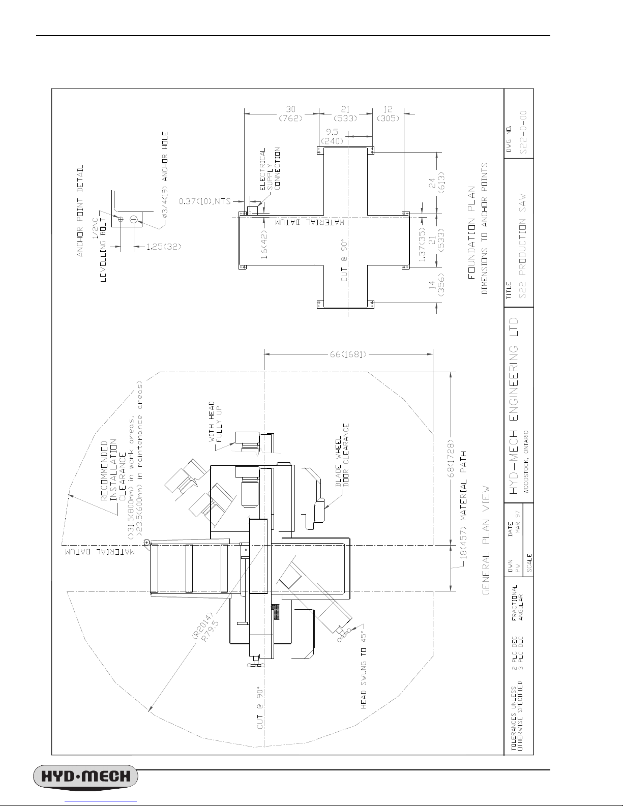
LAYOUT DRAWINGS
Pg 3 S22Hce 2002a
Pg 4 S22Hna 2002a
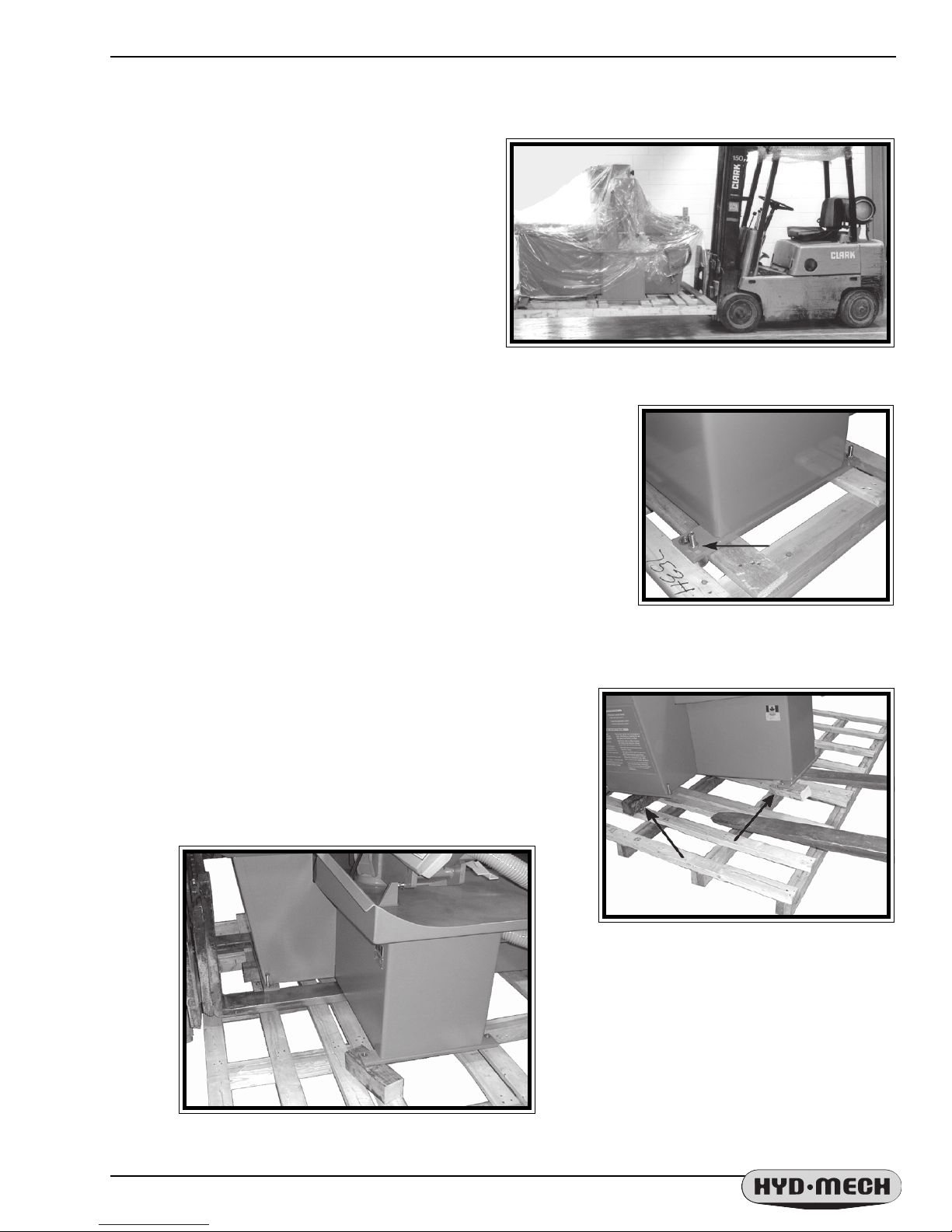
LIFTING THE S-20 SERIES II
The S-20 is shipped with a shipping pallet attached
to the saw. When lifting the pallet with a forklift truck
make sure that the load is firmly balanced. The
following photo shows a lift truck lifting the saw and
pallet from the correct side. The pallet length dimension
is 87” (213cm). Minimum fork length of 72” (182cm) is
recommended to safely lift the pallet.
WRAPPED FOR SHIPPING
The S-20 Series II is shrink-wrapped for shipping
from our plant. Remove the wrapping from around the
saw. Complete the inspection for signs of damage. The
photo shows the floor mounting plates located at the
corners of the saw. Undo the bolts that hold the saw to the pallet. Retain
these bolts to use for levelling. The larger diameter hole is used for
retaining during shipping and for use with concrete floor anchors. The
smaller diameter, threaded holes at each corner are used for levelling the
saw properly .
Lifting the packaged S-20 Series II with a lift truck.
REMOVING THE SAW FROM SHIPPING SKID
Lift the right (drive) side of the saw as shown with a lift truck and
place two blocks under the saw as shown. With a lift truck (fork
length 60” (150cm) and rated for 1800lb (810kg) minimum), lift the
saw from the skid at the FRONT of the machine as shown and place
it where required.
Bolt holding the saw to the skid (4
places).
Blocks placed under the saw.
Lifting the machine with a lift truck from the front
of machine.
Pg 5 S22Hce 2002a
LEVELLING THE SAW
Use a machinist's level across the vise table
to level the saw. Adjust the level with the
levelling bolts supplied. Consideration should be
given to the flow of the coolant as it returns to
the coolant trough at the vise end of the saw.
Levelling to give a small incline towards this
area helps to ensure the coolant supply returns
to the container.
Coolant filter
S25-1-03 &
screen, S22-1-11
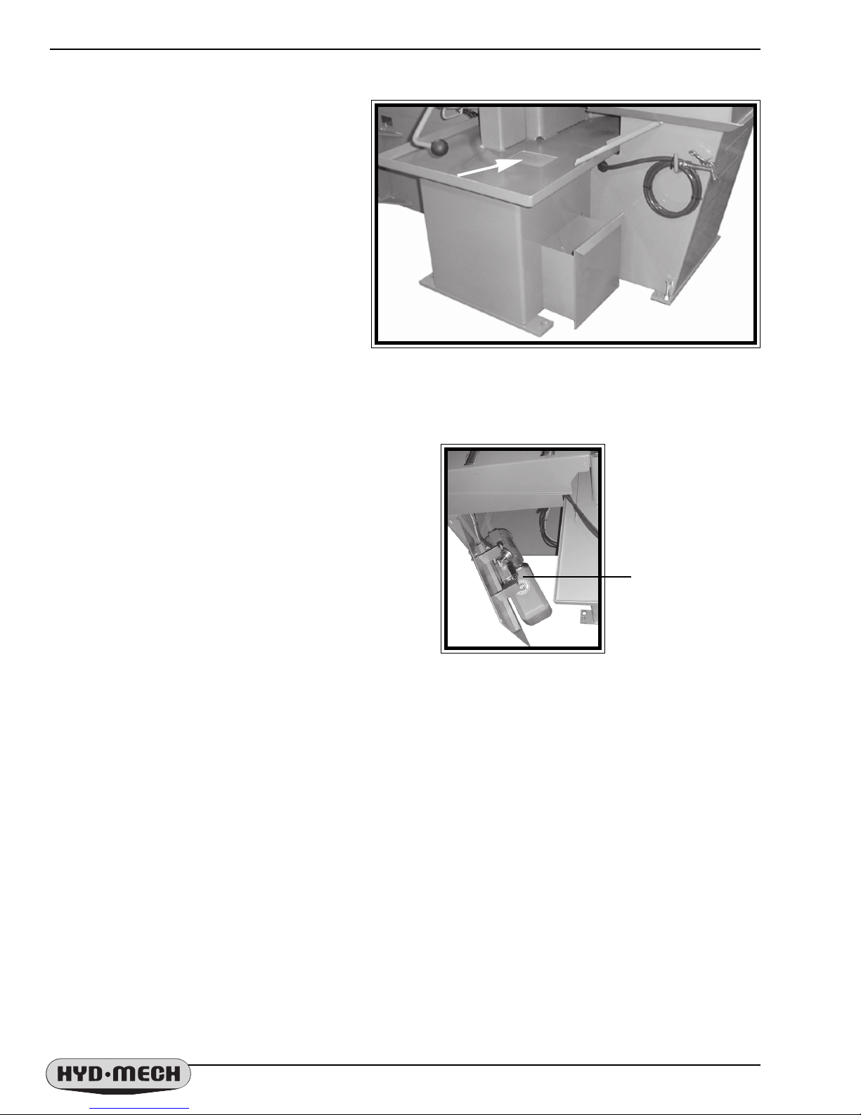
HYDRAULIC OIL
The S-20H option is supplied with T exaco Rando HD46
hydraulic oil. Substitutes should be a #46 hydraulic oil. The
power pack and tank is mounted on the inside of the door
found at the idler side of the infeed table. The tank should
be at least 3/4 full at all times.
Wash Down
Hose
,
Coolant
T ank & Pump
Coolant components (Shown with tank removed).
Hydraulic tank
filler cap is
found
near the pump
& motor
assembly .
The power pack with the
door opened.
CUTTING FLUID
The S20 uses a pump and reservoir to circulate the necessary cutting fluid to the blade for maximum blade life.
Y our saw blade supplier will be able to provide information to the cutting fluid products that are available for your
needs.
No cutting fluid (coolant) is supplied with the machine. There are two types of coolant available:
- oil based; dilute 1:10 ratio (one part concentrated coolant to 10 parts water)
- synthetic; dilute as recommended by manufacturer.
Pg 6 S22Hna 2002a
POWER CABLE ROUTING
The main power cable can be routed up through the bottom of the
head frame to the access holes in the end of the control panel. Cable
liquide tight reliefs should be used to secure the cable into the control
panel to ensure there is no movement of the cable when the machine is
operated.
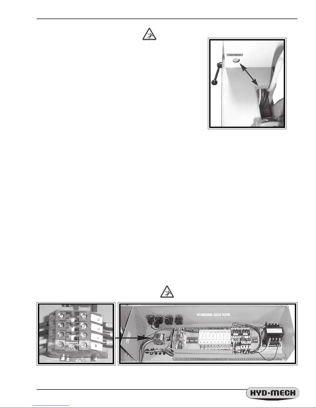
POWER WIRING CONNECTIONS
When the machine has been anchored and levelled the power hook-up is the last installation step. In order to
provide safe operation and to prevent potential damage to the machine, only qualified personnel should make the
electrical connections.
As supplied your new S-20 Series II is set to run on three phase voltage or single phase. The supply voltage of
the machine is displayed on the Serial # Plate and the Voltage Label.
Connection from the Main supply is made to L1, L2, L3, (or L1 & L2 for single phase) and Ground terminals
between the contactor & transformer.
Supply conductors should be rated for the current supplied and should be protected by time delay fusing rated for
the amperage stated on the machine serial plate
CHECK FOR:
- Signs of damage to the electrical cables from shipping or installation.
- Correct phase order. The blade should be running counter clockwise.
(If the blade direction is wrong, two lines should be reversed to correct)
The S-20, with "H" option control panel, opened.L3, L2, L1 and Ground
Pg 7 S22Hce 2002a

THIS PAGE INTENTIONALLY LEFT BLANK

SECTION 2 - OPERATING INSTRUCTIONS
SECTION 2
OPERATING INSTRUCTIONS

SECTION 2 - OPERATING INSTRUCTIONS

OPERATING INSTRUCTIONS
OPERA TOR CONTROL PANEL
The operator control panel provides the operator with all the controls necessary to operate the saw after the
cutting angle has been set and the stock has been loaded and secured. All of the electrical functions are operated
from the control panel. The Vise and Feed Rate setting are both controled with the hydraulic controls shown on the
next page.
ELECTRICAL CONTROLS
COOLANT SWITCH
ON :
OFF :
WASH :
Coolant flow when
blade is running.
No coolant flow.
Constant flow.
BLADE SWITCH
This selector switch starts and
stops the saw blade. The blade will
not start with the Head in the down
position.
HYDRAULIC BUTTON
This button will start the hydraulic
ST AR T Button, system. It will
illuminate when pressed and held
momentarily .
EMERGENCY STOP BUTTON
Pressing the red EMERGENCY STOP
Button STOP Button will turn OFF all
machine functions with the exception of
the coolant if the selector switch is in
the WASH position.
VISE CONTROL
OPEN
the lever is pushed up.
HOLD
position when the lever is in the
center position.
CLOSE
the lever is pushed down.
NOTE:
option is present.
The vise will open when
The vise will hold it's
The vise will close when
See page 14 if the bundling
Pg 9 S22Hna 2002a
HEAD CONTROLS
UP
The head will rise as long as the
lever is pushed up.
HOLD
current position when the lever is in this
position.
DOWN
Feed Rate.
FEED RA TE DIAL
the head will descend can be set on the
scale of 1 to 10. As the number
increases so does feed rate.
The head will stay at it's
The Head will descend at set
The speed at which

BLADE BASICS
Technology is rapidly changing all aspects of production machining. Metal cutoff is no exception. The
advances made in the bandsaw blade industry have definitely brought down the cost per cut, despite the three fold
higher price of the newer technology blades. V ariable pitch (following page), bi-metal blades (like the 3/4 or 4/6 bimetal blade supplied with the machine) last much longer, cut faster , and more accurately than the conventional
carbon steel blades. In order to take advantage of the superiority of bi-metal blades, it is critical to property “breakin” a new blade. This is accomplished by taking two or three cuts through solid four or five inch diameter mild steel
at an extremely slow feed rate. These two or three slow cuts sufficiently lap (polish) the new blade so that it does
not snag the material being cut. Proper break-in will alleviate blade vibration, improve surface finish and accuracy ,
and improve expected blade life.
1. A new blade must be properly "broken-in". Proper break-in will alleviate blade vibration, improve surface
finish and accuracy , and extend blade life. The most convenient way to do this is to cut the intended work-piece,
at the standard recommended blade speed for that material, but with the feed rate reduced to about 25% of
normal. Near the end of the first cut, increase the feed rate again, and once again when the blade approaches
the end of the second cut. Keep increasing feed rate in this fashion, so that normal feed rate is reached after
300 to 500 sq. cm of cutting.
2. Generous coolant application is essential with almost all materials. A high quality and well mixed
coolant will dramatically extend blade life, and will increase cutting rate and surface finish. On those few
materials where coolant is undesirable, a slight coolant flow or periodic oiling of the blade is necessary to
prevent the blade from being scored by the carbide guides.
3. The stock being cut must be securely clamped in the vises. Stock movement during cutting will strip
blade teeth. Noticeable stock vibration reduces cutting performance and blade life - consideration should be
given to reorientation of the stock, or additional clamping measures (e.g. wood between vise jaws and work-
piece).
4. The proper blade speed for the work-piece material must be selected.
Use the following chart as a starting point.
- Blade speeds higher than recommended will quickly dull the blade. Blue chips are evidence of excessive
blade speed.
- Lower than recommended speeds will not prolong blade life, and will require reduced feed rate - but
reduced speeds may be helpful in reducing vibration, and will increase blade life in that case.
5. The proper feed rate must be applied. Feed Rate is the speed which the head "free-falls", and is set with
the feed rate control knob. The head will descend more slowly when the blade encounters the work-piece but
the force of the blade on the work will not be changed unless the setting is changed. Verification of proper feed
rate is provided by the appearance of the cut chips which ideally form nicely curled "clock springs". (Note that
cast irons, and interrupted cuts result in short, broken chips even at ideal feed rates).
- Excessive feed rate will result in short blade life and/or crooked cuts.
Pg 10 S22Hna 2002a
( in SFM )( in SFM )
( in SFM )
( in SFM )( in SFM )
(
310310
310
310310
220220
220
220220
140, 220140, 220
140, 220
140, 220140, 220
140, 220140, 220
140, 220
140, 220140, 220
90, 14090, 140
90, 140
90, 14090, 140
140, 220140, 220
140, 220
140, 220140, 220
90, 14090, 140
90, 140
90, 14090, 140
140, 220140, 220
140, 220
140, 220140, 220
140, 220140, 220
140, 220
140, 220140, 220
140, 220140, 220
140, 220
140, 220140, 220
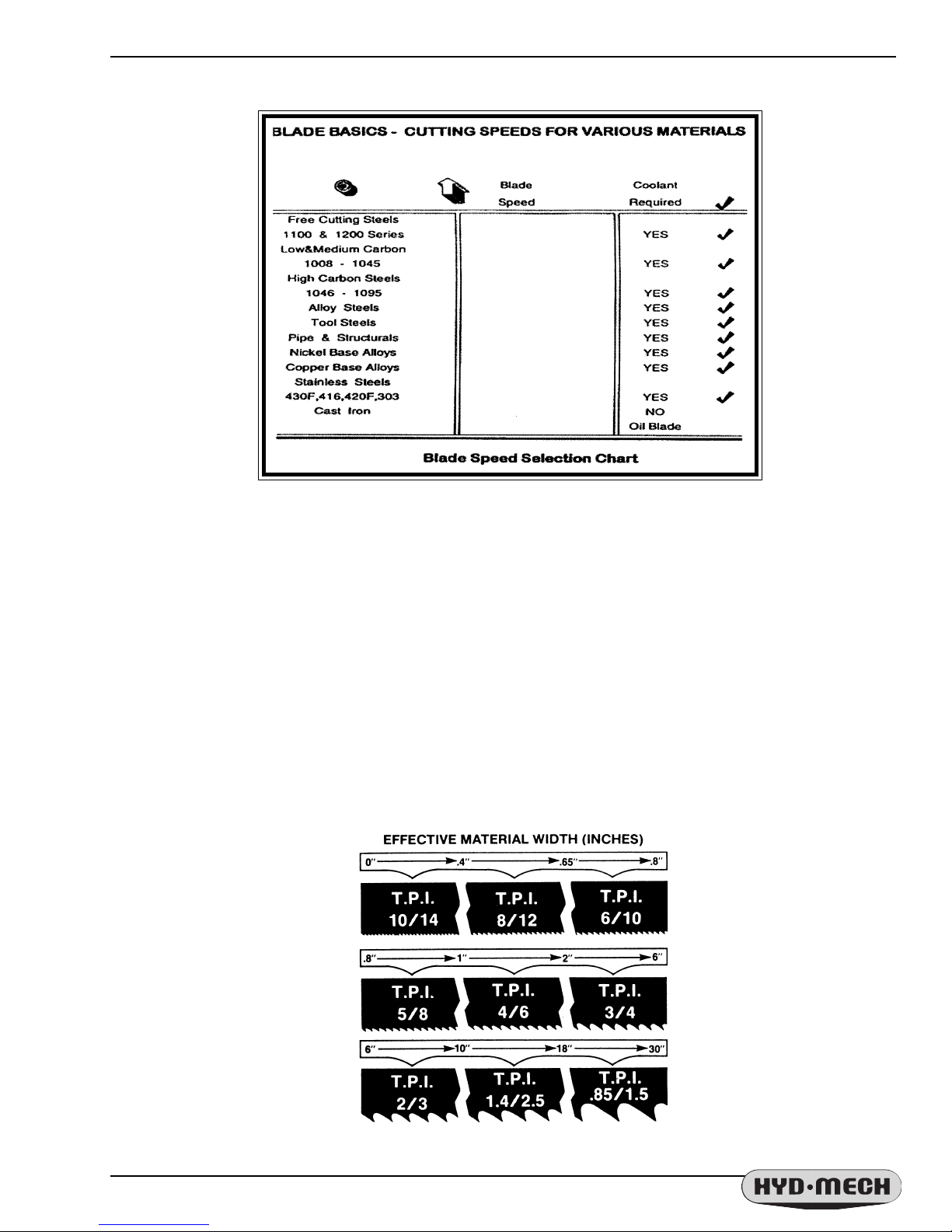
DETERMINE OPTIMUM BLADE PITCH - TEETH PER INCH (T.P.I.)
Selecting a blade with proper tooth pitch is important in order to achieve optimal cutting rates and good blade
life.
For cutting narrow or thin wall structural materials a fine, blade with many teeth per inch (T.P.I.)is recommended.
For wide materials a blade with a coarse pitch should be used. See the sketch below for the blade pitch changes
fordiffering effective material widths.
It is impractical to change the blade to the proper pitch every time a different width of material is cut and it is not
necessary , but remember that the optimum blade will cut most effic iently. T oo fine a blade must be fed slower on
wide material because the small gullets between the teeth will get packed with chips before they get across and out
of the cut. Too coarse a blade must be fed slower because it has fewer teeth cutting and there is a limit to the depth
of a cut taken by each tooth.
Optimum Blade Pitch ( T.P.I. ) for Material Width ( Inches )
Pg 11 S22Hna 2002a
 Loading...