

YEAR OF MANUFACTURE: ______________
USE AND MAINTENANCE MANUAL
S20DSP
EN


Introduction and technical specifications 1---1......................
Foreword 1---1..........................................................
Machine presentation 1---1...............................................
Machine specification 1--- 2...............................................
Dimensions 1 --- 4........................................................
F un c t io n a l p a r t s 2 --- 1............................................
S20DSP model 2 --- 1.....................................................
Cutting head 2---2.......................................................
Vice 2 --- 3..............................................................
C o n t r o l P a n e l 2 --- 3......................................................
Tu r nt a b l e 2 --- 4..........................................................
F i x e d p l at f or m 2 --- 4.....................................................
M o t i o n --- v a ri a t o r --- r e d u c e r u n i t 2 --- 5.......................................
Base 2 --- 6..............................................................
Safety and accident prevention 3---1................................
U se o f t h e m a ch i ne 3 --- 1.................................................
General recommendatio ns 3---2...........................................
Recommendations to the operator 3--- 3....................................
Machine safety devices 3--- 5..............................................
Reference standards 3---5................................................
Protection against accidental contact with the blade 3--- 6......................
Electrical equipment 3--- 6................................................
Emergency devices 3---7..................................................
Noise level of the machine 3---8...........................................
Noise level measurement 3--- 8............................................
Noise level values 3--- 8...................................................
Vibration emission 3 --- 9..................................................
Electromagnetic compatibility 3--- 9........................................
Machine installation 4--- 1........................................
Packaging and storage 4---1...............................................
Anchoring the machine 4--- 4..............................................
Minimum requirements 4--- 4..............................................
C h e c k l i s t 4 --- 5..........................................................
Connection to t he power supply 4 --- 6.......................................
Description of machine operation 5---1.............................
Control panel description 5---1............................................
Basic instructions for carrying out a cutting operation cycle 5--- 3................
Manoeuvring the cutting head 5---3........................................
Clamping the work piece in the vice 5--- 3...................................
Rapid vice positioning 5---4...............................................
R a p i d v i c e t r a n s l a t i on 5 --- 6...............................................
Wi d t h o f c u t 5 --- 6.......................................................
Preliminary check list for cutting operation 5---7.............................
Semi---automatic operating cycle 5--- 7......................................
Execution of inclined cuts 5---10............................................
Loading side rollerway position 5---10.......................................
Angled cuts 45˚ to the left 5--- 11...........................................
Angled cuts 60˚ to the left 5--- 12...........................................
Angled cuts 45˚ to the right 5--- 14..........................................
Angled cuts 60˚ to the right 5--- 15..........................................

Diagrams, exploded views and replacement parts 6---1................
Hydraulic diagram 6---2..................................................
How to read the wiring diagrams 6---3......................................
D2 --- Letter codes used to designate the type of component 6--- 5...............
Standardised Wiring Diagrams S20DSP (CENELEC Standard) 6---8............
IUD/IUV card 6 --- 21.....................................................
Exploded views 6--- 22.....................................................
M o t o r u n i t 6 --- 2 2.........................................................
Driving pulley unit 6---24..................................................
Front flywheel assembly 6--- 26..............................................
F i x e d w o rk t ab l e 6 --- 2 8....................................................
Cutting head cover 6---30..................................................
C y l i n d e r s 6 --- 3 2.........................................................
Base assembly 6---34......................................................
C o n t r o l p a n e l 6 --- 3 6......................................................
Vice assembly 6---38......................................................
A d j u s t me n t s 7 --- 1...............................................
Displaying and editing the set---up parameters 7--- 1..........................
Set language parameter 7---2..............................................
Set parameter for machine type 7--- 2.......................................
Semiautomatic---Dynamic and Manual operation setting (optional) 7 --- 2.........
Pedal control setting (optional) 7--- 3.......................................
Optional inverter presence settings 7--- 3....................................
Blade speed proximity settings 7--- 3........................................
Minimal lubrication system settings 7---3....................................
FCTI / FCTA digital output enabling setting 7--- 3............................
Blade stop setting 7---3...................................................
Cutting vice opening setting 7--- 4..........................................
Cutting vice opening/closing time setting 7---4...............................
Machine maximum power input setting 7---4................................
Measurement unit setting 7---4............................................
Setting minimum blade tensioning 7---5.....................................
Display backlighting time setting 7---5......................................
Cutting head stroke 7 --- 5.................................................
Software version and total use time of the machine 7--- 8......................
Adjusting the display brightness 7--- 8.......................................
Machine working pressures 7---9...........................................
Hydraulic pressure 7 --- 9..................................................
Cutting head 7---10.......................................................
Blade tensioner slide play adjustment 7--- 10..................................
B la d e g ui d e c o m p o n e n t s 7 --- 1 1.............................................
Blade guide heads 7--- 11..................................................
Blade steady buttons 7 --- 11................................................
Blade guide plates 7--- 11..................................................
Blade 7 --- 1 4.............................................................
Tool changeover 7--- 14....................................................
Blade perpendicularity 7--- 16..............................................
Blade orthogonality 7---17.................................................
Front flywheel 7--- 18......................................................
Rear flywheel 7---18......................................................
Maintenance and choice of consumables 8---1.......................
The role of the operator 8--- 1.............................................

Maintenance requirements 8--- 2...........................................
General maintenance 8--- 2...............................................
Daily 8 --- 2.............................................................
Weekly 8 --- 2............................................................
Monthly 8---3...........................................................
Maintenance of working parts 8 --- 3........................................
Consumable materials 8 --- 3...............................................
Oils for oleopneumatic circuit 8--- 3........................................
Oil for lubricant/coolant fluid 8--- 4.........................................
Cutting speed and choice of tools 9---1..............................
Cutting speed 9--- 1......................................................
Standard machine 9---1..................................................
Choice of blade 9---2....................................................
Saw tooth pitch 9---2.....................................................
Cutting speed and downstroke speed 9--- 2..................................
Ty p e s o f s w ar f : 9 --- 3.....................................................
Lubricant/coolant fluid 9---4..............................................
Blade structure 9---4.....................................................
B la d e t y pe s 9 --- 5........................................................
C o n v e n t i on a l r ak e 9 --- 5..................................................
Po s it i v e r a ke 9 --- 5.......................................................
Va r i a b le p i tc h 9 --- 5......................................................
Variable pitch blades with 0˚ cutting angle 9--- 6..............................
Variable pitch with positive rake (from 9 to 10 degrees) 9---6...................
Set: 9 --- 6...............................................................
Standard or splayed set 9---6..............................................
U nd u la t ed s e t 9 --- 7......................................................
Alternating grouped sets 9---7.............................................
A lt e rn a t i n g s e t 9 --- 7.....................................................
Blade selection table relating to cutting speed and downstroke speed 9--- 8.......
Classification of steels 9---9...............................................
Classification of steels 9 --- 10...............................................
Troubleshooting 10---1............................................
Troubleshooting blade and cutting problems 10--- 1............................
Troubleshooting 10---7....................................................
D i a g n o s t i c s s y st e m 1 0 --- 8..................................................
Machine alarms and emergencies 10---10.....................................


1--1
Introduction and
technical
specifications
Foreword
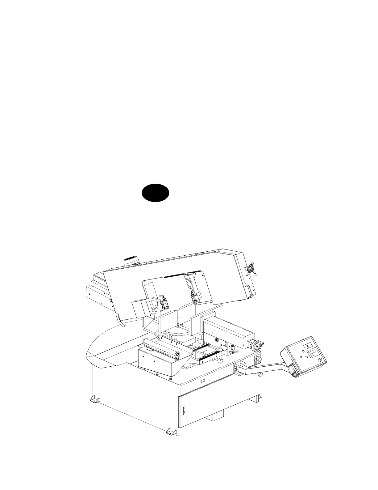
Hyd---Mech in response to modern production techniques, has developed the new
S20DSP.
This work tool has been designed to satisfy the wide range of cutting needs of a
modern workshop with simplicity and reliability, while at the same time complying with all EEC safety standards.
The S20DSP is structurally rigid, silent and safe: it produces a minimum of waste
while its great versatility makes it suitable for cutting various materials such as
stainless steel light alloys, aluminium, copper and bronze at high speed and with
high precision.
Its high cutting capacity, combined with the possibility of making inclined cuts
from 60˚ left to 60˚ right, make this model the ideal solution for satisfying the
wide strange of cutting needs of machine shops, turneries, structural steel shops
and engineering workshops.
We congratulate our clients on having chosen this product, which will give
effective and faithful service for many years, especially if the instructions
contained in this use and maintenance manual are carefully followed.
This band saw has been exclusively designed to cut metals.
Machine presentation
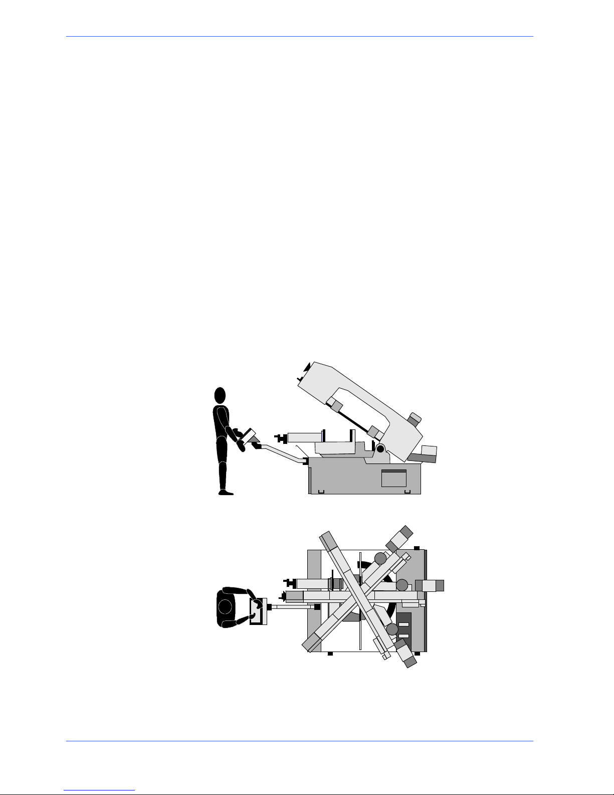
Functioning is SEMI ---AUTOMATIC.
In Semi ---automatic mode, after setting the head cutting stroke on the control
panel and the head downstroke speed, the operator positions the vice 2÷3 mm
from the workpiece and presses the start button (or optional foot pedal if fitted)
on the control panel to start up the band saw. The vice then clamps the material,
the head lowers, cuts the piece and returns to its start position and the vice opens
again.
1.Thecuttervicecloses
2. The head lowers until the cut is made
(FCTA)
3. The head returns to
start position (FCTI)
4. The cutter vice
opens
Warning
1
1--2
2
Use and maintenance manual S20DSP
Machine specification
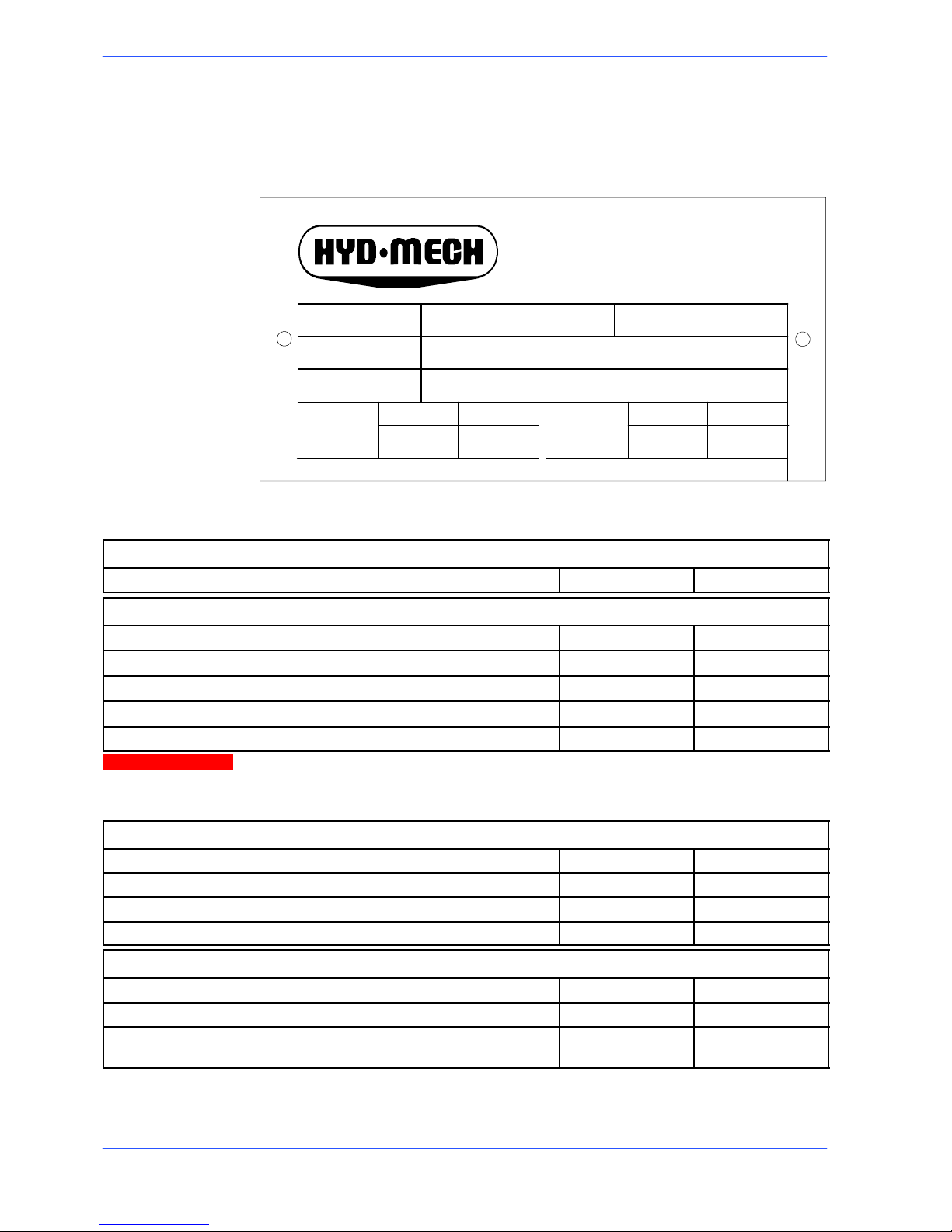
Theanodisedaluminiumnameplateisrivetedonthesideofthemachine;the
same data are reproduced on the declaration of conformity included with this use
and maintenance manual.
bar bar
------ --
V
1PH
AVA
3PH
model
air pressure
data code
oil pressure
HYD--MECH
The Rock Solid Solution
When communicating with the Technical Service department, the model, serial
number and year of manufacture of the machine must be quoted.
CUTTING SPEEDS
Blade rotation speed mt/min
15 100
BAND SAW
Rated size mm
4500 x 27 x 0,9
Max/min blade length mm
4500 ± 40
Blade height mm
27
Blade width mm
0,9
Band saw tension Kg
1250
When choosing the cutting tool, if its dimensions do not correspond to those
included in the ”Rated size” section, check that the dimensions at least fall
within the admissible max/min specifications.
RATED ELECTRICAL POWER
Head spindle motor KW 1.,5
Electric coolant pump motor KW 0,1
M1 power pack motor (optional) KW
0,37
Max installed power KW 1,97
WORKING PRESSURE
Working pressure blade tensioning/detensioning
Kg
1250/900
Head working pressure in the ascent phase (optional) Bar 20
Vice working pressure during opening/closure phase (AV ver-
sion)
Bar 6
N.B.
Attention

1--3
3
Introduction and technical specifications
LUBRICANT/COOLANT FLUID AND OIL
Oil for blade t ensioner unit (optional) capacità Lt 8,5
Lubricant/coolant fluid (oil concentration 5---6%) capacità Lt 200
VICE
Vice max. opening mm 455
SPINDLE MOTOR
No.of poles Current (Volts) Absorption
(Amps)
Power (Kw) rpm
4 400 3,7 1,5 1410
Stator wound with enamelled copper wire, class H 200˚C.
Class F insulation (limit temperature TL 155˚C).
IP 55 protection rating (total against contact with live parts, water sprayed from all directions, with shaft oil
seal).
Conforming to CEI norms, publication: IEC 34 of 01/07/1985.
Example of class F insulation: in air--cooled machines at an ambient temperature of 40˚ C (according to CEI 2--3 and IEC 85), the allowable overtemperature is 100˚ C (where 100
ٛ
C represents the allowable DT).
ELECTROPUMP MOTOR
Single phase; Frequency 50 Hz.
Voltage ( Vo l ts) Absorption
(Amps)
Power (Kw) rpm Delivery rate
lt/min
Head (mt. )
230 0,30 0,09 2800 24 1,5
400 0,18 0,09 2800 24 1,5
Protection rating IP 55.
Conforming to CEI norms, publication: IEC 34 of 01/07/1985.
CUTTING CAPACITY
Section
0˚ 330 330 450x330
45˚ a 320 300 300x300
60˚ a 210 200 200x200
45˚ ' 320 300 300x300
60˚ ' 210 200 200x200
N.B.

1--4
4
Use and maintenance manual S20DSP
Dimensions
MACHINE INSTALLED
Work table he ight mm 880
Weight Kg 1110
12001300800
2260
1200 310230
880
2580
1200
3300
1300 800
1200 780600
650
PAC KED WEIGHT
Wooden cage and pallet Kg 130
Wooden pallet Kg 70
2900
1800
1800
2--1
Functional parts
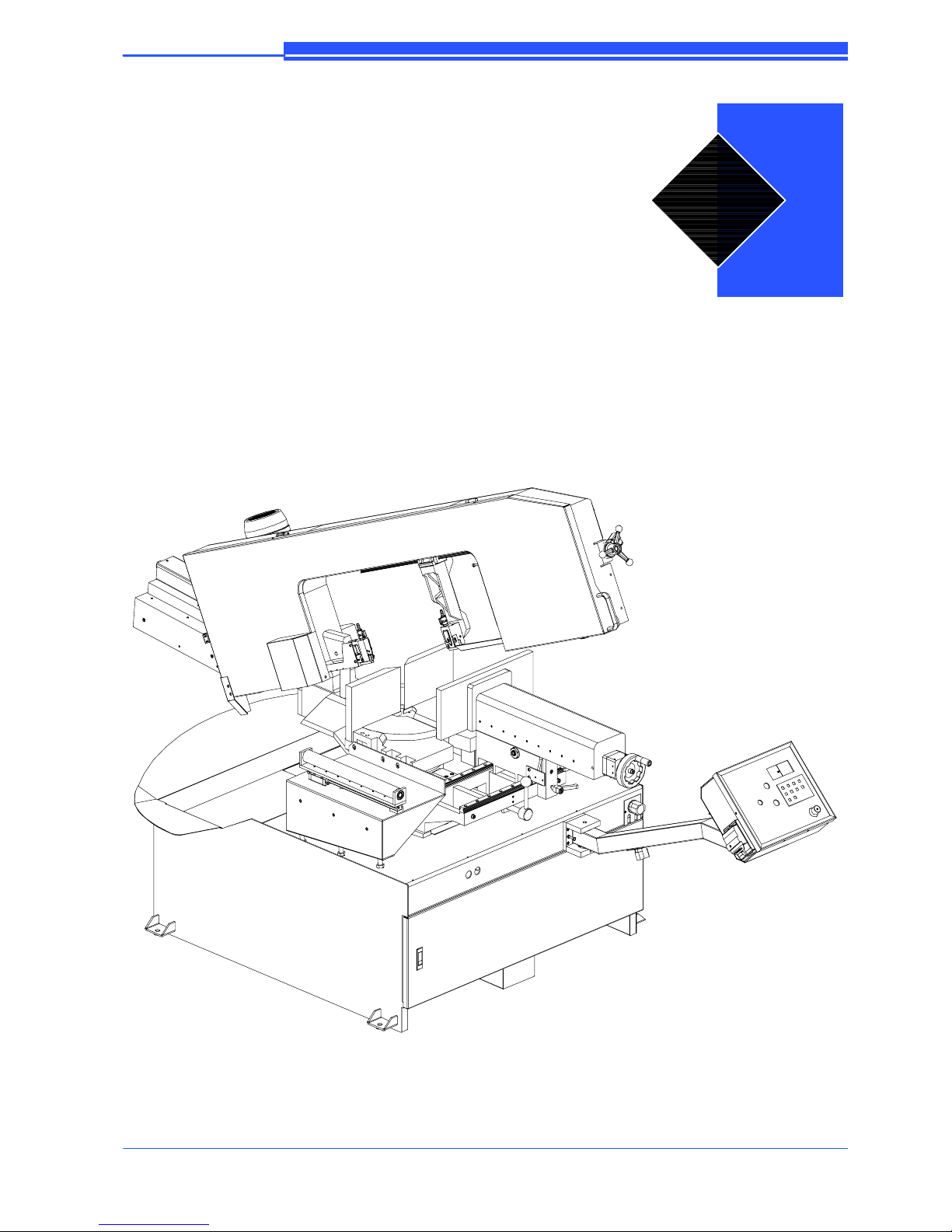
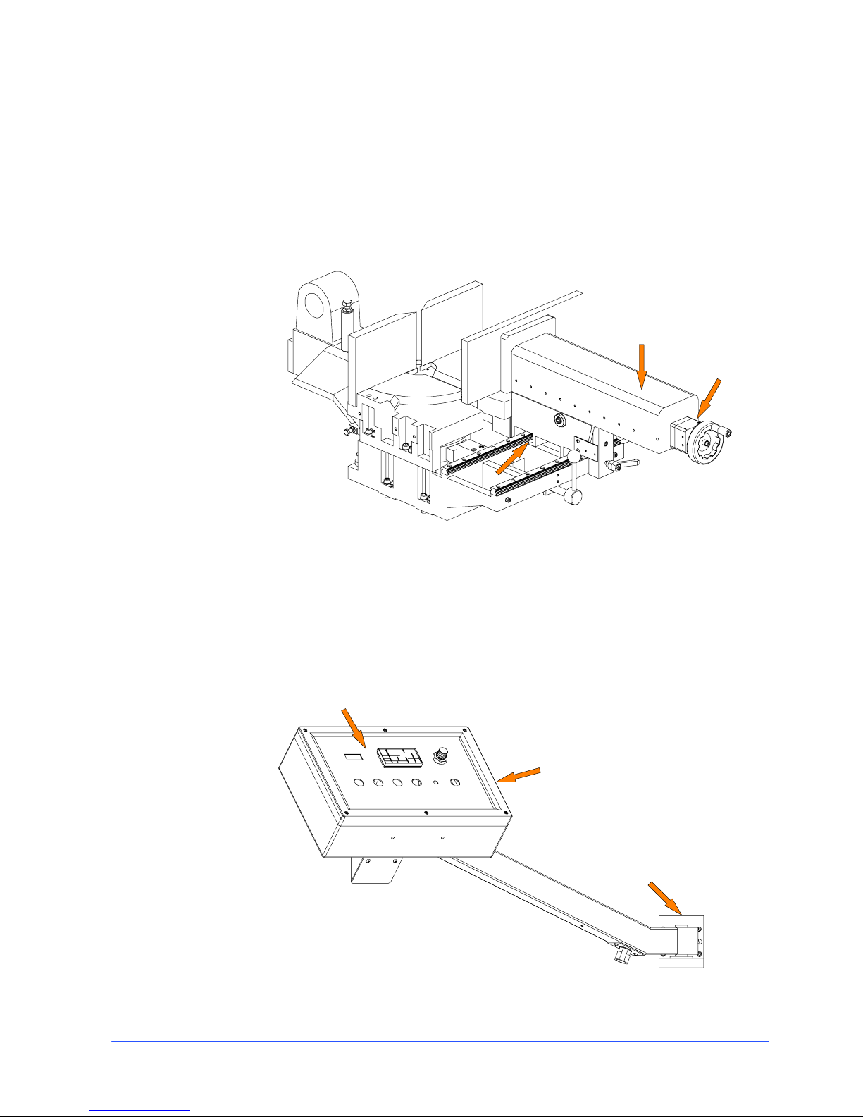
S20DSP model
In order for the user to move towards a full understanding of how the machine
works, which is described in detail in the chapter 5, this chapter deals with the
main units and their locations.
CUTTING HEAD
CONTROL
PANEL
VICE
TURNTABLE
BASE
2
2--2
6
Use and maintenance manual S20DSP
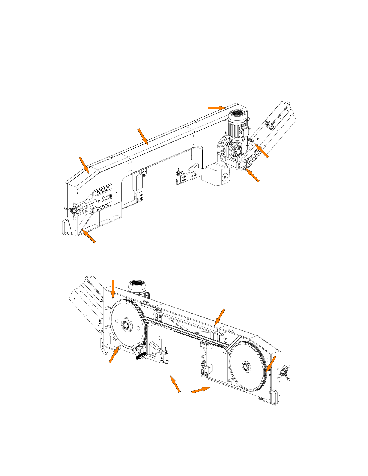
Cutting head
The oerating head is the element that performs the cut and is made up of a bow
made from a fusion of cast iron onto which the band, the band guide elements,
the band tensioning unit and the mechanical speed variator are mounted. The
operating head is restricted in its movements by the articulated joint on the
rotatng platform.
Motor
Blade guide heads
Belt tensioning wheel
Transmission box
Drive pulley
Idle pulley
Rear flywheel
Speed variator
Cutting head beam
Front flywheel
Blade casing
2--3
7
Functional parts
Vice
The vice is the unit that clamps the workpiece during cutting. It consists of a vice
support, commonly known as a “lead nut”, fixed to the work table, and a lead
screw with a sliding support on which the mobile jaw is mounted. It can run
transversely with respect to the cutting surface, or lengthways, for opening and
closing, on the linear guides and slides with recirculation of pre---loaded spheres.
Theviceismanuallynearedtothematerialtobecutusingahand---wheeland
blocking is performed using a hydraulic cylinder (in the AV version).
Slideway
Handwheel
Vice support (lead nut)
Control Panel
The control panel has a protection rating of IP 54 and contains the electronic
equipment. Access to the control panel is protected by a safety panel mounted on
hinges and fastened with screws, specially designed to prevent tampering. The
control panel swivels on two articulated joints so that it can be positioned by the
operator for greater ease---of---use and safety.
Control panel
Articulated joints
Control console
2--4
8
Use and maintenance manual S20DSP
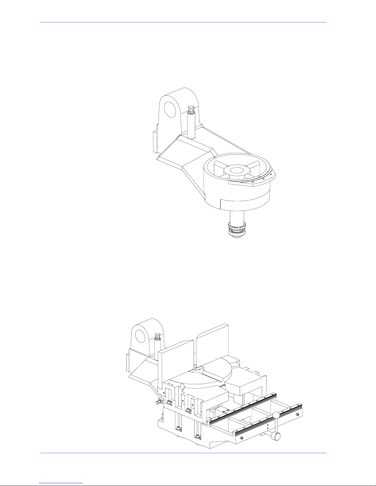
Turntable
Made from a fusion of cast iron it makes up the fulcrum of the cutting band. By
releasing the blocking lever on the fixed platform right and left rotation of the
bow is consented.
Fixed platform
It is made up of two parts, upper and lower, which close the rotating and platform
and support the cutting surface in interchangeable steel.
The lower part is the resting base of the rotating platform, cutting surface and
vice. It is free to run transversely on linear guides and slides with re---circulation
of pre ---loaded spheres. It is integral to the base and the rear part has the
reference strokes for 60˚ left and 60˚ right cuts.
2--5
9
Functional parts
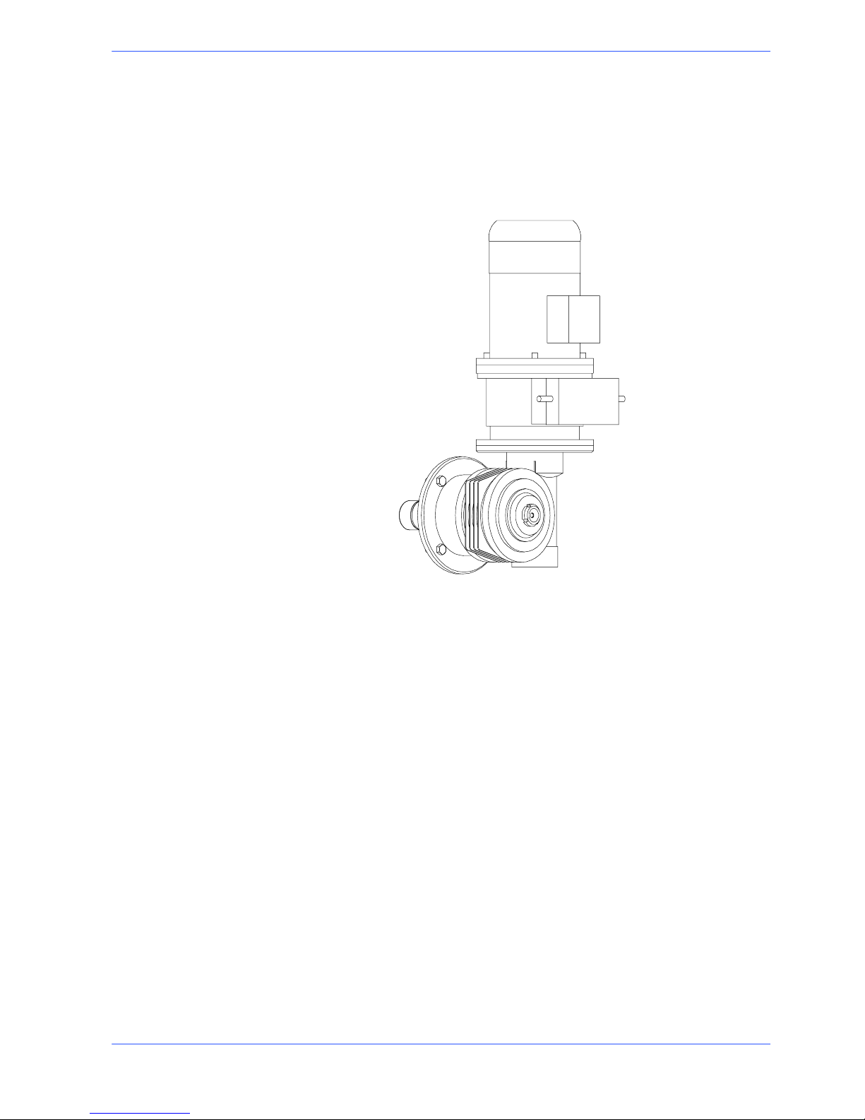
Motion--variator--reducer unit
Rotation of the band is performed by a system made up of a motor connected to a
variator and a mechanical speed reducer.
This unit allows rotation of the band in a continuous adjustment range that goes
from 20 to 100m/min.
2--6
10
Use and maintenance manual S20DSP
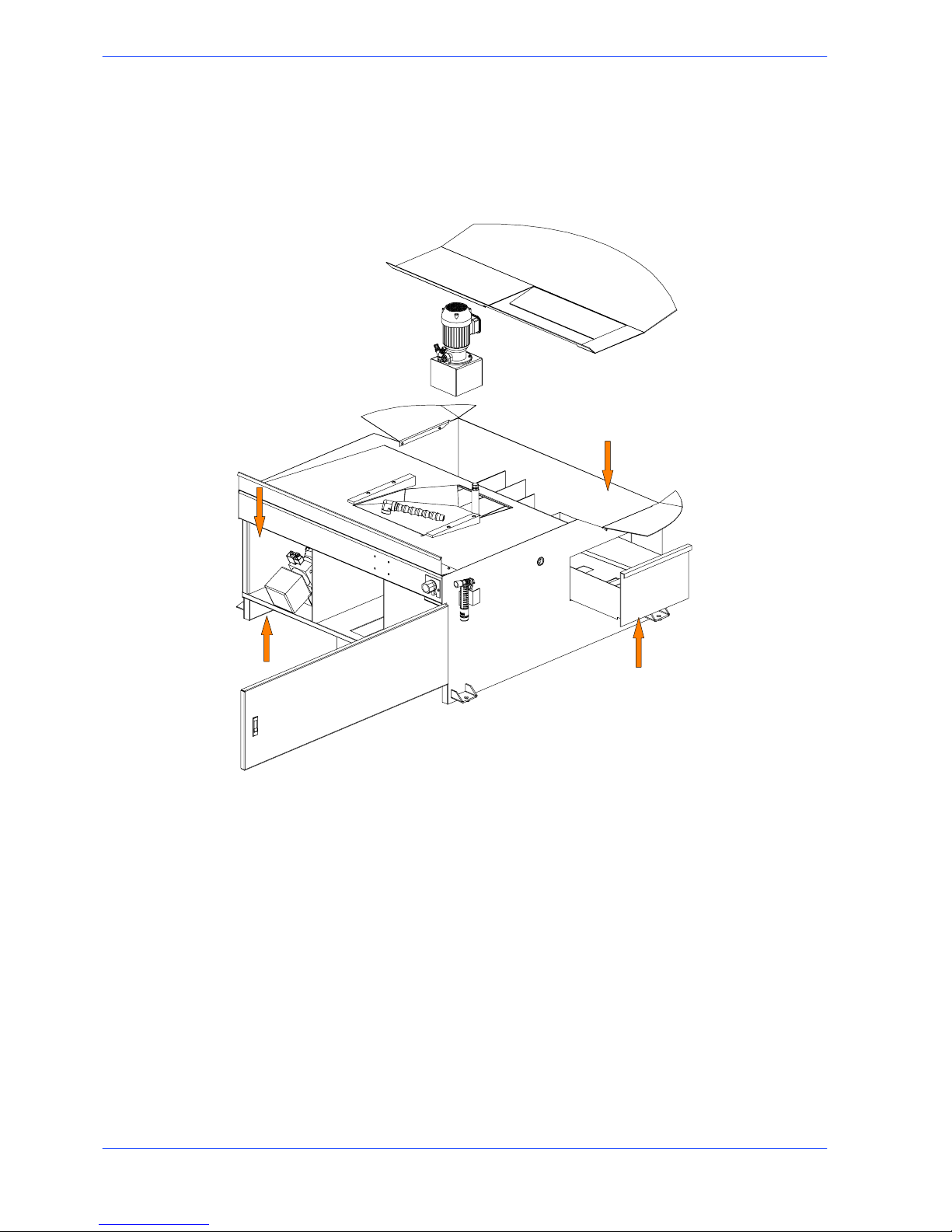
Base
This unit features a large coolant collection surface which conveys the coolant to
the rear tank via the tank cover, and a swarf collection drawer. An electric pump
is housed inside the tank which draws the clean fluid from the filter system.
Lubricant/coolant tank
Electric pump housing
Swarf collection drawer
Hydraulic single box housing

3--1
Safety and accident
prevention
The S20DSP has been designed and produced in accordance with European
standards. Forthecorrectuseofthemachinewerecommendthattheinstructions contained in this chapter are carefully followed.
Use of the machine
The S20DSP band saw cutting machine is intended exclusively for cutting metallic
materials, ferrous or non ---ferrous, in section or solid.
Other types of material and machining are not compatible with the s pecific
characteristics of the saw.
The employer is responsible for instructing the personnel who, in turn, are
obliged to inform the operator of any accident risks, safety devices, noise
emission and accident prevention regulations provided for by international
standards and national laws regarding the use of the machine. The operator must
be perfectly aware of the position and function of all the machine’s controls.The
instructions, warnings and accident prevention standards in this manual must be
respected without question by all those concerned.The following definitions are
those provided for by EEC MACHINES DIRECTIVE 98/37/CE :
H “Danger zone”: any zone in and/or around a machine in which the presence of a
person constitutes a risk for the safety and health of that person.
H “Person exposed”: any person finding himself either completely or partly in a
danger zone.
H “Operator”: the person or persons given the responsibility of installing, operating,
adjusting, maintaining, cleaning, repairing or transporting the machine.
The manufacturer declines any responsibility whatsoever, either civil or criminal, should there be unauthorised interference or replacement of one or more
parts or assemblies on the machine, or if accessories, tools and consumable
materials are used that are different from those recommended by the manufacturer itself or if the machine is employed in a plant system and its proper
function is thereby altered.
Attention
3
3--2
12
Use and maintenance manual S20DSP
General recommendations
LIGHTING
Insufficient lighting for the types of operation envisaged could constitute a safety
hazard for the persons concerned. For this reason, the machine user must provide
lighting in the working area sufficient to eliminate all shadowy areas while also
avoiding any blinding light concentrations. (Reference standard ISO 8995---89
“Lighting in work environments”).
CONNECTIONS
Check that the power supply cables and pneumatic feed systems comply with the
maximum machine absorption values listed in the “Machine Specification” tables;
replace if necessary.
EARTHING
The installation of the earthing system must comply with the requirements set out
in IEC STANDARD 204.
OPERATOR POSITION
The position of the operator controlling machine operations must be as shown in
the diagram below.
3--3
13
Safety and accident prevention
Recommendations to the operator
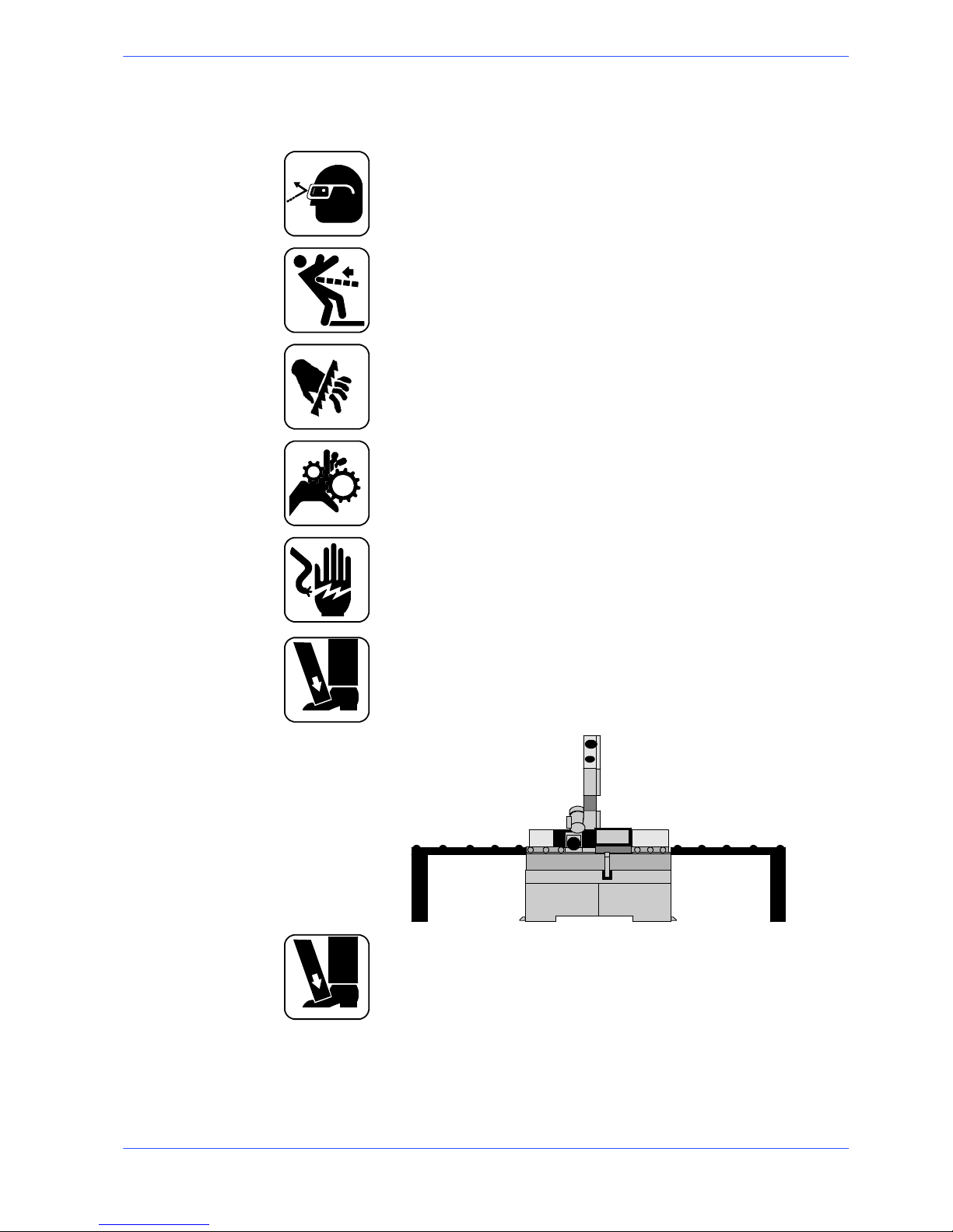
Always wear proper goggles or protective glasses.
Do not use the machine wit hout the guards in position. Replace the polycarbonate windows , if subject to corrosion.
Do not allow ha nds or arms to encroach on the cutting zone while the
machine is in operation.
Do not wear oversize clothing with long sleeves, oversize gloves, bracelets, necklaces or any other object that may become entangled in the machine duri ng working; long hair must be tied back and bunched.
Alwaysdisconnectthepowersupplytothemachinebeforecarryingout
any maintenance work whatsoever, including in the case of abnormal
operation of the machine.
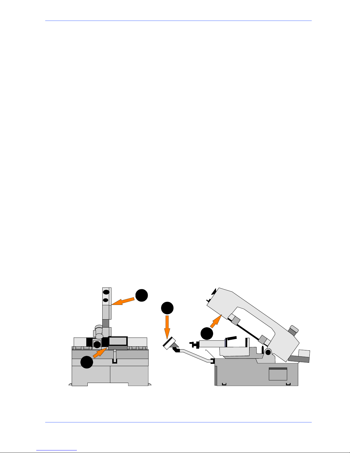
Before starting cutting operations, support the material at both ends of
the machine using the support arm --- standard, or OPTIONAL accessories such as the feed and discharge roller tables shown in the diagram
below. Before removing the devices supporting and moving the material,
fasten the latter in place using the machine’s clamping devices or other
suitable equipment.
mm. 1500
mm. 1500
FEED ROLLER TABLE DISCHARGE ROLLER TABLE
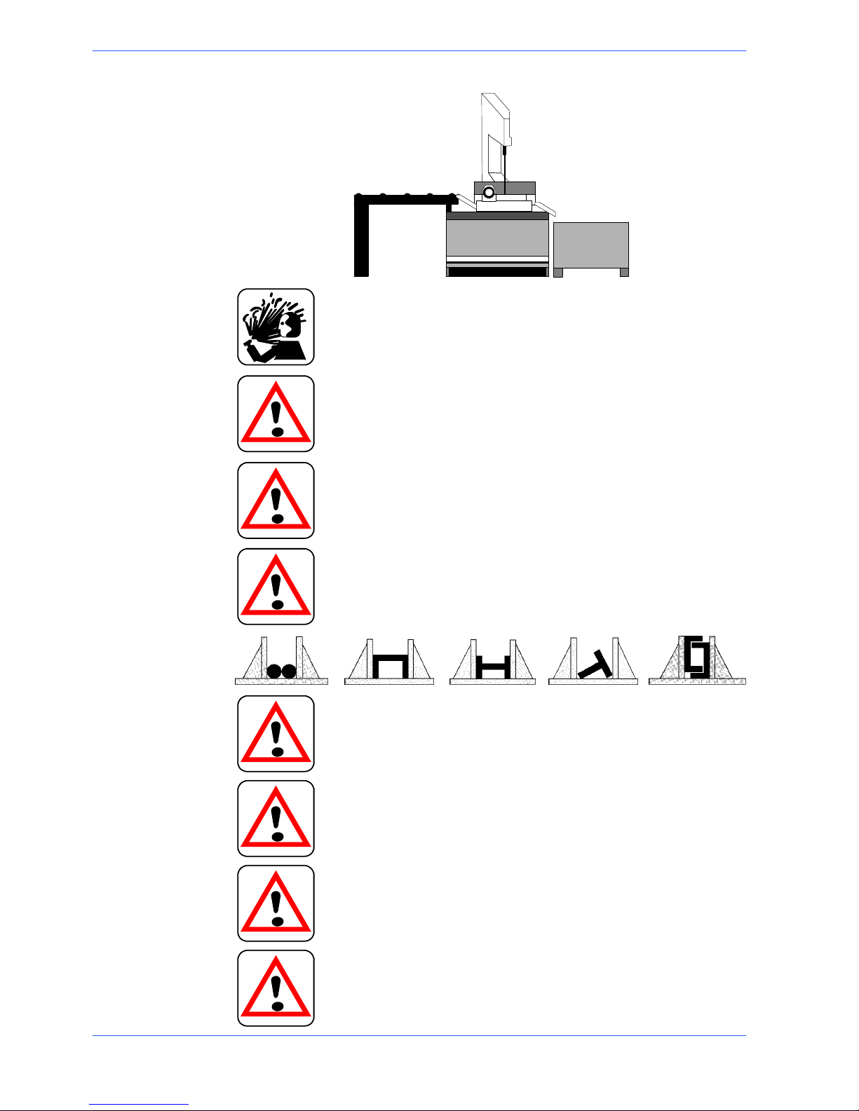
Arrange recovery/collection systems for the cut pieces, such as metal
baskets, for example.
3--4
14
Use and maintenance manual S20DSP
mm. 1500
FEED ROLLER TABLE
COLLECTION BASKET
Any maintenance work on the hydraulic or pneumatic systems must be
carried out only after the pressure in the system has been released.
The o perator must not perform any risky operations or operations not
required for the machining operati on under way (e.g. remove swarf or
metal shavings from the machine while cutting).
Remove equipment, tools or any other objects from the cutting zone;
always keep the working area as clean as possible.
Before starting any cutting operations, ensure that the workpiece is
securely held in the vice and the machine has been set correctly. A
number of examples of how to clamp different profiles correctly in our
machines are shown below.
Do not use the machine to cut pieces that exceed the capacity of the
machine as listed in the machine specifications.
Never move the machine while it is cutting.
Do not use blades of dif ferent sizes to those recommended in the
machine specifications.
When cutting very short pieces, make sure that they are not dragged
behind the support shoulder, where they could jam in the blade.

3--5
15
Safety and accident prevention
When the hydraulic vice is used automatically, check it actually locks the
piece, as its stroke is 8 mm only, and that the tightening pressure is correct.
When working on the band saw, wear gloves only when handling
materials and for tool changing or adjustment operations. Only perform
one operation at a time and do not hold more than one item or operate
more than one device simultaneously. Keep hands as clean as possible.
Warning: if the blade jams in the cut, press the emergency stop push--button immediately. If this does not free the blade, slowly loosen the
vice, remove the piece and check the blade or blade teeth for breakage.
Replace the blade if necessary.
Before carrying out any repair work on the machine, consult the
Hyd--- Mech Technical Assistance Service: this can be done through a
representative in the country of use of the machine.
Adjustmentoftheblade---guideheadmustonlybecarriedoutwiththe
machine at a standstill.
Machine safety devices
This use and maintenance manual is not intended as purely a guide for the use of
the machine in a strictly productive environment, it is instead an instrument
providing information on how to use the machine correctly and safely. The
following standards are those specified by the EEC Committee in the directives
regarding safety of machinery, health and safety at work, personal protection and
safeguarding of the environment. These standards have been applied to the
S20DSP band saw.
Reference standards
MACHINE SAFETY
H EEC MACHINES DIRECTIVE 98/37/CE ;
H EEC directive no. 89/336 ”EMC -- Electromagnetic Compatibility”;
H EEC Directive No. 73/23 known as ”Low voltage directive”.
HEALTH AND SAFETY AT WORK
H EEC Directive No. 80/1107; 83/477;86/188;88/188; 88/642 for the protection of
workers against risks caused by exposure to physical, chemical and biological agents during working;
H EEC Directive No. 89/391 and Special EEC Directives No. 89/654 and No. 89/655
for improvements in health and safety at work;
H EEC Directive No. 90/394 for the protection of workers against risks deriving from
exposure at work to carcinogenic substances;
3--6
16
Use and maintenance manual S20DSP
H EEC Directive No. 77/576 and No. 79/640 on safety signs at work.
PERSONAL PROTECTION
H EEC Directive No. 89/656 and No. 89/686 on the use of personal protection de-
vices.
ENVIRONMENTAL PROTECTION
H EEC Directive No. 75/442 on waste disposal;
H EEC Directive No. 75/439 on the disposal of used oil.
H Directive 2002/95/EC on the restriction of the use of certain hazardous substances
in electrical and electronic equipment (RoHS).
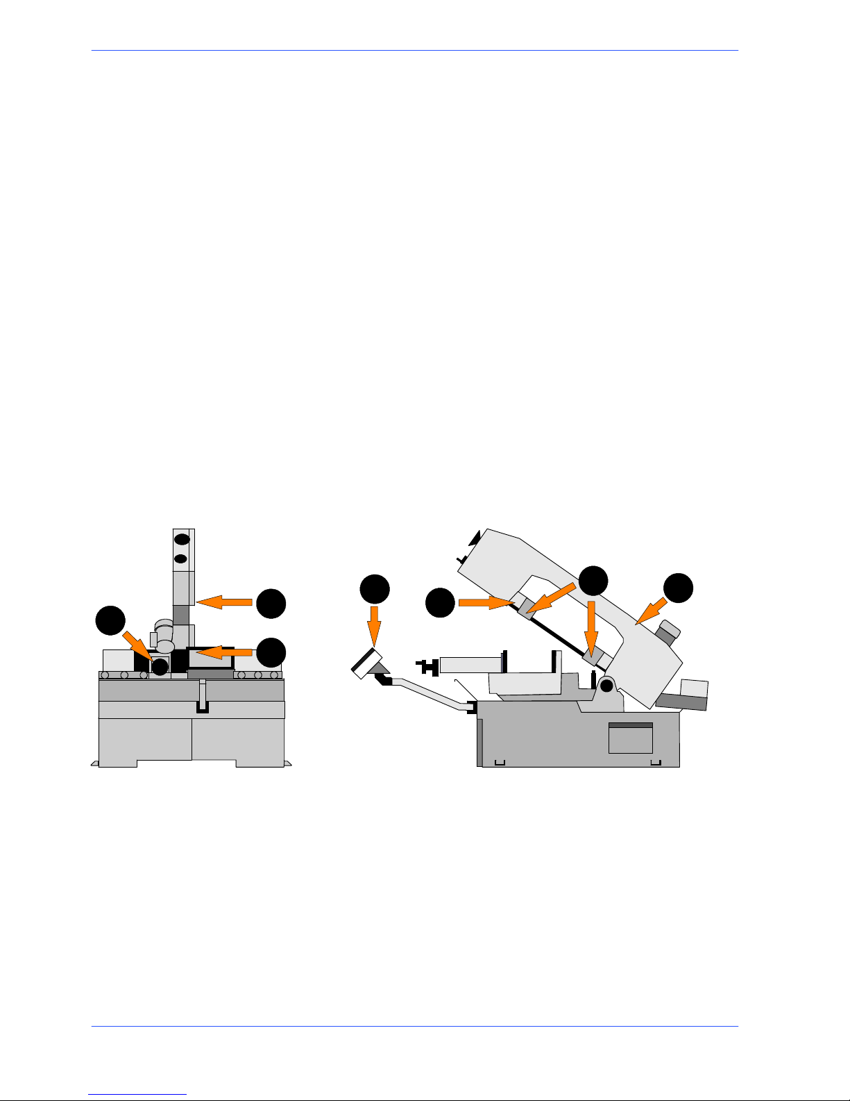
Protection against accidental contact with the blade
1. Metal guard screwed to the rear blade guide head (machine side);
2. metal guard screwed to the front blade guide head (operator side);
3. front head sliding support: when the head is at maximum aperture, the
support ensures that the blade is covered, leaving free only the part of the
blade engaged in the actual cutting, in accordance with Presidential Decree
no. 547/55, art. 108;
4. hinged protective cover over blade, fitted with removable closing devices;
5. blade guide plates completely covering the blade teeth;
6. the cutting vice is operated by hydraulic devices, with a max. stroke of 8 mm;
the jaws locking the piece must be moved at a distance of 2P3 mm from the
piecetobemachined.
7. programming and control panel mounted on an articulated, adjustable arm,
so that the operator is always at a safe distance from moving components.
5
2
1
6
4
3
7
Electrical equipment
In accordance with Italian standard CEI 60204---1, April 1998, derived from
European Standard EN 60204---1 publication IEC 204---1, 1997:
H Access to electrical control panel limited by screws and panel ---lock device,
allowing panel to be opened only after the electricity supply has been turned
off;
H 24 Vac Control voltage for actuators, in accordance with chapter 6 or
European Standard ”Control and indication circuits”, paragraph 2 ”Control
Circuits” sub---section 1 ”Preferential voltage values for control circuits”;
3--7
17
Safety and accident prevention
H plant short---circuit protection by means of rapid fuses, earthing of all plant
parts connected with work as well as all foreseeable accidental contact; a
thermal ---magnetic overload cutout switch shuts down the motor;
H protection from accidental start---up by a minimum voltage relay in case of
power failure.
Emergency devices
In accordance with Standard CEI 204 ---1:
H Chapter 5 Section 6 Sub--section 1 ”Emergency stop device”: «the emergency
stop device immediately stops all the dangerous and other functions of the machine»;
H chapter 6 Section 2 Sub--section 4 Point 7 ”Protective guards”: «the removal of
protective guards designed to prevent access to dangerous parts or zones causes the
machine to stop immediately; replacing the guards does not restart the functions,
which must be reset».
...Emergency devices applicable to the S20DSP:
1. Emergency stop: a non---return mushroom---head pushbutton, colour red on
yellow background, is located on the control panel of the machine. To release
the pushbutton, the actuator must be rotated 45˚. After the emergency situation has been resolved, the machine must be reset.
2. Automatic thermal ---magnetic cutout switch with thermal--- magnetic relay:
The machine’s automatic switch, positioned on the left---hand side of the
base, has two protective systems against the lack of voltage. In fact, if there is
a lack of voltage, it disconnects all electrical devices, blocking the machine
immediately and impedes the automatic restore of the voltage. The other
function is that of re---arming the circuit breaker relay, positioned to protect
from the overloads of current.
3. Pressure transducer for monitoring the blade tension: the machine stops immediately if the blade breaks or the tensioner cylinder pressure drops.
4. Protective guard for blade: a coded key microswitch is operated if the blade
cover is accidentally or intentionally opened during the machine operating
cycle, immediately shutting down all functions.
1
2
3
4

3--8
18
Use and maintenance manual S20DSP
Noise level of the machine
Noise can cause hearing damage and represents one the problems faced by many
countries who adopt their own standards. In accordance with the EEC
MACHINES DIRECTIVE 98/37/CE , we are listing the standards that specify
noise levels for machine tools. This chapter also reports the noise levels produced
by the S20DSP during its various operating phases and the methods used for
measuring these levels. The Italian standard governing this aspect is
D.M.n.277/91 drawn from EEC Directives 80/1107, 82/605, 83/477, 86/188, 88/642,
UNI EN ISO 4871 (1998).
Noise level measurement
Noise levels are measured using an instrument known as an Integrator noise--meter which registers the equivalent continuous acoustic pressure level at the
work station.The damage caused by noise depends on three parameters: level,
frequency and duration. The equivalent level concept Leq combines the three
parameters and supplies just one indication. The Leq is based on the principle of
equal energy, and represents the continuous stationary level containing the same
amount of energy, expressed in dBA, as that actually fluctuating over the same
period of time.This calculation is made automatically by the integrator noise --meter. The measurements are taken every 60 seconds, in order to obtain a
stabilised value. The reading stays on the display for a sufficient time to enable a
reading to be taken by the operator.Measurements are taken by holding the
instrument at approximately 1 metre from the machine at a height of 1.60 metres
above the platform at the operator’s work station.
Two measurements are taken: the first while the machine operates without cutting
anything, the second while cutting in manual mode.
Noise level values
Identification
Machine type Band saw for metal applications
Model
S20DSP
Reference standard ISO 3746
Results
Description
C53 ste el cut --- pipe 356 x 286 mm
Bimetal band 4500 x 27 x 0, 9
Tes t 1st 0
Results
Mean sound level (Leq) 71,00 dB (A)
Environmental correction (K) 3,76 dB(A)
Peak sound power (Lw) 81,93 dB(A)
Descriprion
C 40 steel cut --- HPE 400 x 300 mm
Bimetal band 4500 x 27 x 0, 9
Test 2nd
Results
Mean sound level (Leq) 68,92 dB(A)
Environmental correction (K) 3,76 dB(A)
Peak sound power (Lw) 81,90 dB(A)
Description
34CND6 material cut ---pipe Ø 150 mm
Bimetal band 4500 x 27 x 0, 9
Test 3rd
Results
Mean sound level (Leq) 69,07 dB(A)
Environmental correction (K) 3,76 dB(A)
Peak sound power (Lw) 79,78 dB(A)

3--9
19
Safety and accident prevention
Vibration emission
This sawing machine complies with the norms EN1299 and EN1033, as the
machine vibration emission on the devices controlled by the operator does not
exceed the threshold of 2.5 m/s
2
Electromagnetic compatibility
As from 1 January 1996 all electrical and electronic appliances bearing the CE
marking that are sold on the European market must conform to Directive
89/336/EEC and 70/23/CEE and 98/37/CEE. The prescriptions regard two specific
aspects in particular:
1. “EMISSIONS: during its operation, the appliance or system must not emit spurious
electromagnetic signals of such magnitude as to contaminate the surrounding
electromagnetic environment beyond clearly prescribed limits”;
2. “IMMUNITY: the appliance or system m ust be able to operate correctly even when
it is placed in an electromagnetic environment that is contaminated by disturbances
of defined magnitude”.
The following text contains a list of the applied standards and the results of the
electromagnetic compatibility testing of machine model S20DSP; Test report no.
140201.
Product family standards
H CEI EN 55011 (1999) Industrial, scientific, and medical radio frequency appliances
(ISM). C haracteristics of radio frequency disturbance -- Limits and methods of
measurement.
H CEI EN 50370--2 (2004): Electromagnetic Compatibility (EMC) -- Product family
for machine tools -- Part 2: Immunity.
Basic standards
H EN 61000--4--2 + A1 + A2 (1996--1999--2001) Electromagnetic Compatibility
(EMC) -- Part 4: Test and measurement techniques -- Section 2: Electrostatic discharge immunity tests -- Basic publication.
H EN 61000--4--3 + A1 + A2 (2003 -- 1999 -- 2001): Electromagnetic Compatibility
(EMC) Part 4: Test and measurement techniques -- Section 3: Radiated, radio-- frequency, electromagnetic field immunity test.
H EN 61000--4--4 + A1 + A2 (1996 -- 2001 -- 2002) Electromagnetic Compatibility
(EMC) -- Part 4: Test and measurement techniques -- Section 4: Fast transients/
bursts immunity tests -- Basic publication.
H EN 61000--4--5 + A1 (1995 -- 2001): Electromagnetic Compatibility (EMC) -- Part
4: Test and measurement techniques -- Section 5: Surge immunity test.
H EN 61000--4--6 + A1 (1997 -- 2001) Electromagnetic Compatibility (EMC) -- Part
4: Test and measurement techniques -- Section 6: Immunity to conducted interference, induced by radio frequency fields.
H EN 61000--4--11 + A1 (1995 -- 2001): Compatibilità Elettromagnetica (EMC) Part
4: Test and m easurement techniques -- S ection 11: Voltage dips, short interruptions
and voltage variations immunity tests.

3--1020Use and maintenance manual S20DSP
Emissions
CONDUCTED EMISSIONS
Gate A Freq. (MHz) Q --- p e a k l i m i t ( d B u V) Mean value limit (dBuV) Result
A.C. power supply
input
0.15 --- 0.5
0 . 5 --- 5
5 --- 3 0
79 --- 73
(linear reduction with
log of frequency)
73
73
66 --- 60
(linear reduction with log of fre-
quency)
60
60
Complies
IRRADIATED EMISSIONS
Gate Freq. (MHz) Q--- peak limit (10 m)
(dBuV/m)
Result
Enclosure 30 --- 230
230 --- 1000
40
47
Complies
Immunity
IMMUNITY TO ELECTROSTATIC DISCHARGES
Gate Test levels Evaluation criterion Result
Enclosure contact 4 kV
steel plate 4 kV
in air 8 kV
B Complies
IMMUNITY TO VOLTAGE (BURSTS)
Gate Test levels Evaluation criterion Result
A.C. power supply in-
put
2kV B Complies
IMMUNITY TO HIGH VOLTAGE PULSES (Surge)
Gate Test levels Evaluation criterion Result
A.C. power supply in-
put
1 kV (Phase --- phase)
2 k V ( P ha s e --- e a r th )
B Complies
IMMUNITY TO DIPS AND SHORT VOLTAGE INTERRUPTIONS (PQT)
Gate Test levels Evaluation criterion Result
A.C. power supply in- 70% per 0.5 periods B Complies
ppp
y
put
0% per 0.5 periods
40% per 5 periods
40% per 50 periods
B
p
IMMUNITY TO CONDUCTED ELECTROMAGNETIC FIELDS
Gate Test levels Evaluation criterion Result
A.C. power supply in-
put
10V A Complies
IMMUNITY TO IRRADIATED ELECTROMAGNETIC FIELDS
Gate Test levels Evaluation criterion Result
Enclosure 10 V/m A Complies
4--1
Machine installation
Packaging and storage
Hyd---Mech use packing materials that guarantee the integrity and protection of
the machine during its transport to the customer.
The type of packing differs according to the size, weight and destination.
Therefore the customer will receive the machine in one of two following ways:
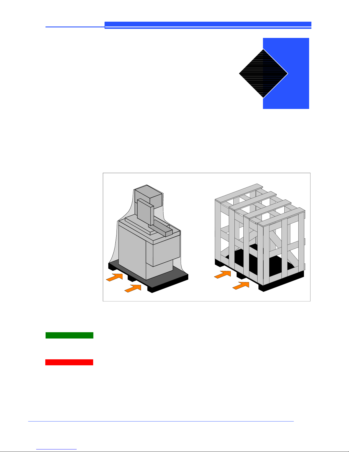
1. on a pallet with straps and heat--- shrink plastic;
2. on a pallet with straps, heat---shrink plastic and a wooden crate.
In both cases, for correct balancing the machine must be handled using a
fork--lift truck, inserting the tines at the points indicated by the arrows, using
the reference marks on the crate itself.
Before carrying out lifting operations, make sure that the weight of the machine, as indicated on the crating or other packaging, is within the forklift truck
load limit.
Warning
Attention
4
4--2
22
Use and maintenance manual S20DSP
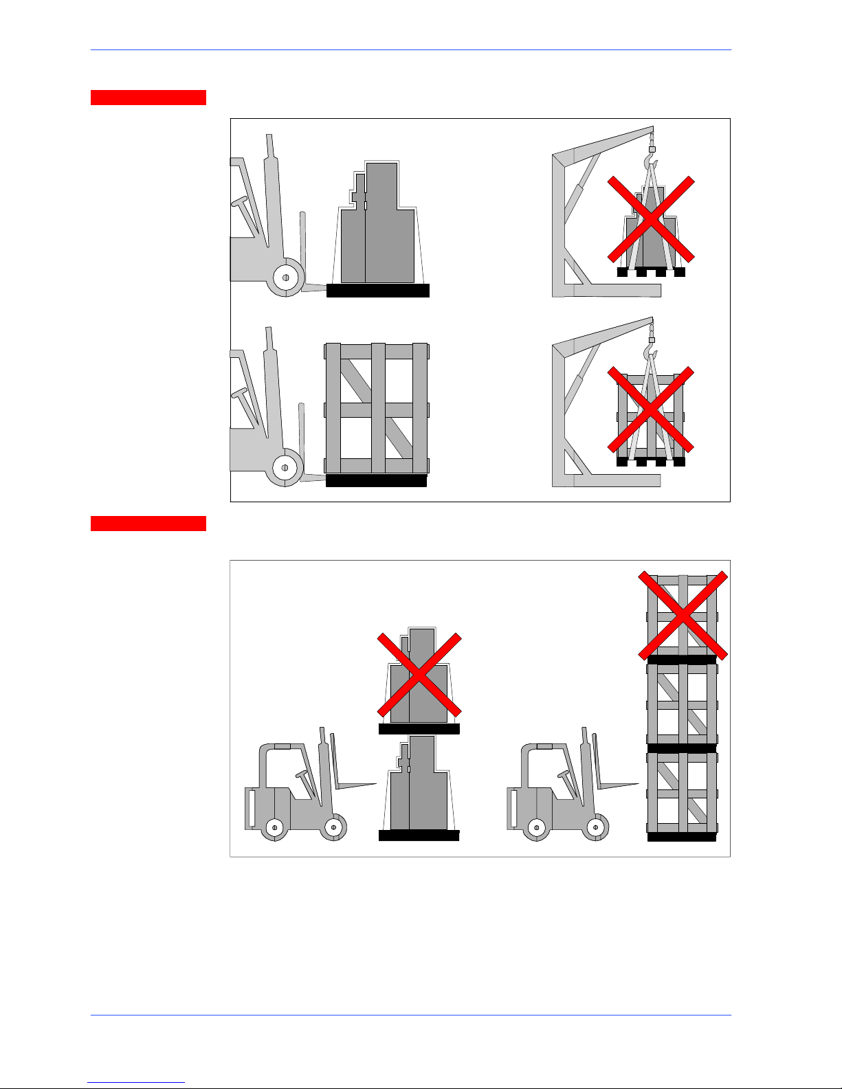
Do not handle the packed machine using slings.
When storing, machines palletized and shrink--wrapped must not be stacked
two high, and machines pallettized and crated must not be stacked three high.
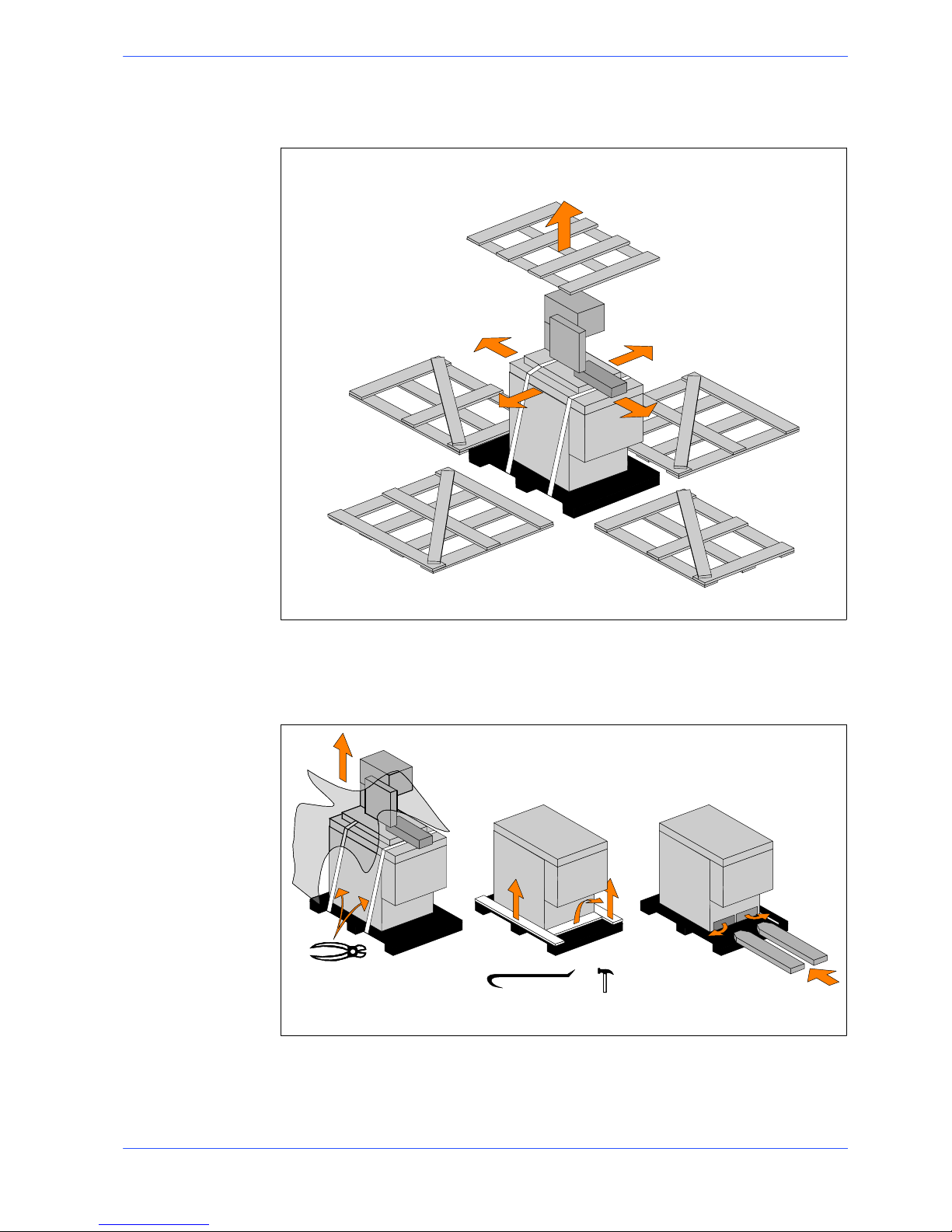
To install the machine, first remove the packing, paying particular attention not to
cut any electric wires or hydraulic hoses; if necessary use pliers, a hammer and a
cutter.
Open crate in the illustrated order:
Attention
Attention
4--3
23
Machine installation
1. remove nails and lift the top of the cage;
2. remove nails and lower walls;
2
2
2
2
1
3. remove heat---shrink covering;
4. remove the straps;
5. remove nails from pallet securing planks and remove planks;
6. remove the front panel and insert fork tines.
3
4
5
6
To locate the machine in the workplace, the machine dimensions and necessary
operator working space, including the spaces laid down in safety standards, must
be taken i nto account.
4--4
24
Use and maintenance manual S20DSP
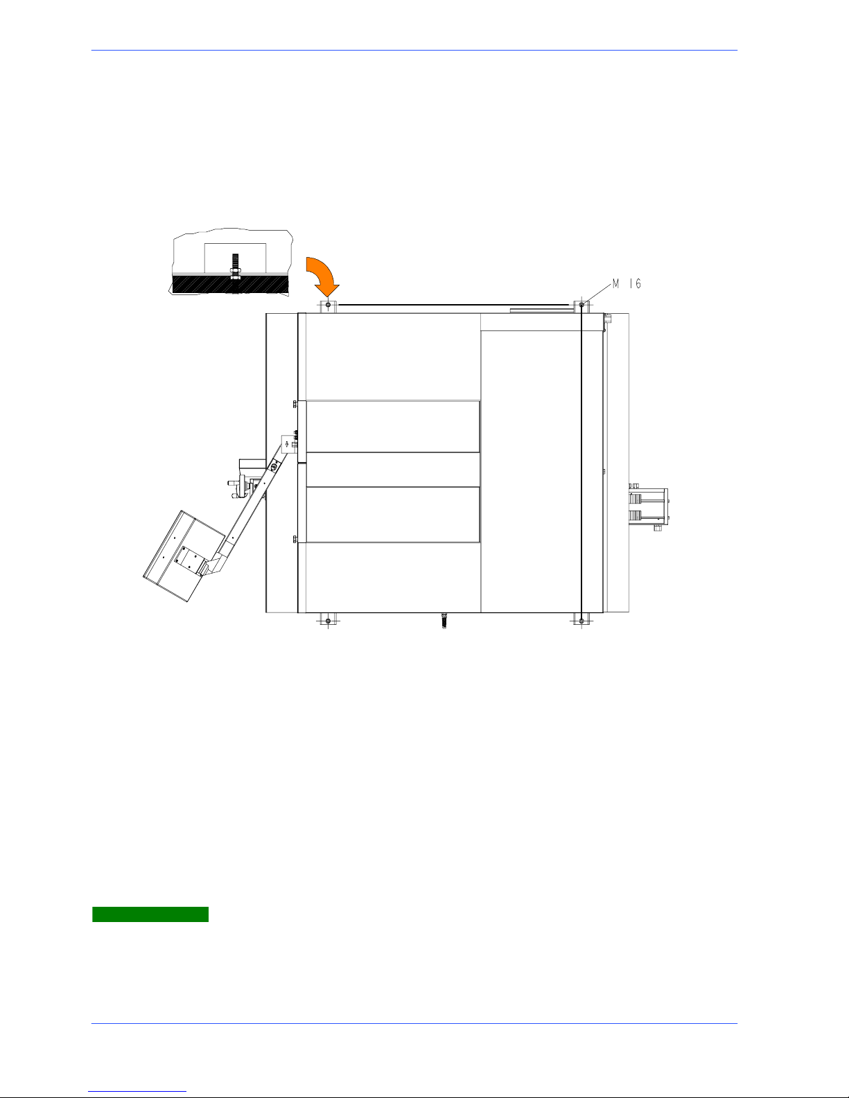
Anchoring the machine
The base of the machine is anchored to the floor by two permanent studs located
on the sides of the base. The studs are screwed into nuts previously sunk into the
concrete, and tightened from above with lock nuts. The schematic specifications
set out in Chapter 1 should be taken into account when positioning the machine.
BASE
1138
1296
Minimum requirements
For the machine to function correctly, the room in which it is to be installed must
satisfy the following requirements:
H power supply voltage/frequency: refer to the values on the rating plate;
H pneumatic operating pressure: not less than 6 Bar and not more than 8 Bar;
H temperature of machine location: from -- 10 to + 50ٛC;
H relative humidity: not more than 90%
H lighting: not less than 500 Lux.
The machine is already protected against voltage variations, but will only run
trouble--free if the variations do not exceed ± 10%.
Warning

4--5
25
Machine installation
Check list
Before starting installation, check that all the accessories, whether standard or
optional, supplied with the machine are present.
CHARACTERISTICS
STANDARD OPTIONAL
Base with large swarf collection drawer, removable coolant tank and electropump for band saw lubrication/cooling
n
Bar support sliding on straight ball guides, located to the left of the cutting
table
n
Mechanical variator of blade rotation from 20 to 100m/min n
Small head mobile blade--- guide running on the linear guides and slides with
re---circulation of pre---loaded spheres
n
Blade 4500 x 27 x 0,9 mm n
Recordable stroke to perform cuts of the same size n
Rotating head on a rotating surface with ball bearings and recordable strokes
allow the stopping and the blocking in correspondence of the 0˚,45˚,60˚
right and 45˚,60˚ left angles
n
Electronic transducer of the stretching of the band with display on the console
n
Blade cleaning device with rotating brushes with movement transmitted from
the pulley engine
n
Designed for transpallet handling systems n
Mobile console to operate while maintaining visual control n
Manual vice with screws with rapid nearing and transfer on the linear guides
a n d s li d e s w i th r e --- c i rc u l a t io n o f p r e --- l o a d e d s p he r es
n
Motorchipdischargerunit n
Steel blade guide head with adjustable hard metal blocks which open to facilitate blade replacement
n
Work table sp ray gun n
Accessory kit n
Vertical roller table pair n
Feed roller table K250 (1500 x N) n
Discharge roller table K250 (1500 x N) n
Cutting oil 5 lt n
*ACCESSORIES AVAILABLE ON REQUEST
The bag of accessories is enclosed in the machine before being packed and
contains:
H hex wrenches 3/4/5/6/10 mm;
H pipe wrench 10 mm;
H 36mm wrench;
H use and Maintenance manual, including order form for parts in relevant user lan-
guage.

4--6
26
Use and maintenance manual S20DSP
Connection to the power supply
Before connecting the machine to the power supply, check that the socket is not
connected in series with other machines. This requirement is fundamental for the
good operation of the machine.
To connect the machine to the power supply, proceed as follows:
" connect the power supply cable of the machine to a plug which matches the
socket to be used. (EN 60204 ---1; par. 5.3.2)
CONNECTION FOR ”5-CORE” WIRE SYSTEMS WITH NEUTRAL
R=L1
S=L2
T=L3
PE = GND
N = NEUTRAL
CONNECTION FOR ”4-CO
R
E” WIRE SYSTEMS WITH NEUTRAL
S=L2
T=L3
PE = GND
R=L1
When using systems with a neutral wire, special care must be taken when connecting the blue neutral wire, in that if it is connected to a phase wire it will discharge the phase voltage to the equipment connected for voltage: phase--
neutral.
" Insert the plug in the socket, ensuring that the mains voltage is the same as
that for which the machine has been setup.
VOLT ?VOLT ?
Attention

4--7
27
Machine installation
" Power up the machine by turning the main switch on the left hand side of the
base (the control console should illuminate);
Check that the motor is rotating in the correct direction. For this check the
following operations must be carried out:
" set the blade tension to 1200 BAR;
" make sure the cover is properly closed: at the back of the cutting head there is
a bayonet limiter for correct cover closure;
" make sure that the machine is not in an emergency condition (red mush-
room ---head pushbutton released);
" after having applied voltage to the machine, set the selector for permission of
motor start up to 1;

4--8
28
Use and maintenance manual S20DSP
" Ensure that the head lowering control is at zero (fully closed);
" start the belt turning by pressing “CYCLE START”;
" if all the above operations have been carried out correctly, the blade motor
will start up and the blade will start rotating.
Ensure that the blade moves in the correct direction as shown in the
above figure. If it does not, simply reverse two of the phase wires on the
machine power supply input.
The sawing machine is now ready to start the work for which it was designed.
Chapter 5 provides a detailed description of the various functions of the machine
and its operating cycles.
Attention

5--1
Description of
machine operation
This chapter analyses all the machine functions. We begin with a description of
the pushbuttons and other components on the control panel.
Control panel description
The figure below shows the control panel of the S20DSP.
Key of control console keyboard
Initialisation key: enables machine operation
Zeroing key for cuts made
5

5--2
30
Use and maintenance manual S20DSP
Blade motor selector: enables or disables
the cutting cicle start button
Gun for washing the work tops
Selection for min. lubrication (optional) No lubricant/coolant key
RESET key: resets the machine after an
emergency condition or conflicting command
Lubricant/coolant spray cock key (only
available during cycle)
Manual cycle key Vice opening
Vice closing
FCTI (Head Upstroke Limit) memory key for Head Positioning System
Semi--- automatic cycle key
FCTA (Head Downstroke Limit) memory key for Head Positioning System
Head “up” key Diagnostics key
Head “down” key Programmed cycle start key
Machine parameters input/edit key
Key for displaying the machine parameters for performing a machining cycle:
TL blade t ension, PT head position, VL
blade speed, T cutting time, PZ cut piece
number, I motor absorption
Electronic speed control (inverter).
Blade cutting speed potentiometer: 20 to
45 m/min. at low speed and 35 to
90 m/min. at high speed
Mushroom head emergency stop button:
when pressed, this button immediately
shuts down the machine. To reset the
emergency stop button, simply rotate
through 45˚

5--3
31
Description of machine operation
Hydraulic adjuster for choosing the head
lowering speed
THERMAL- MAGNETIC CIRCUIT- BREAKER WITH UNDERVOLTAGE
COIL AND DOOR LOCKING DEVICE
On the left side of the control board, the machine is equipped with a main switch
that, when set ON (1), powers the machine. When set to ON (1), this switch
powers up the machine. The main switch is fitted with three power failure
protection systems. In fact, in the event of a power failure, this switch disconnects
all the electrical devices, causing the machine to immediately shut down, and
prevents it from automatically starting up again when power is restored. This
device also resets the thermal relay fitted to protect against current overloads.
Basic instructions for carrying out a cutting operation cycle
Manoeuvring the cutting head
The cutting head may be operated by the head “up” and “down” buttons of the
Head Positioning System (previously illustrated in the key for the control console
keyboard), which are enabled in SEMI ---AUTOMATIC mode.
Head “down” key Head “up” key
During any processing cycle it is possible to control the machine operating
parameters TL (blade tensioning) and PT (head position), pressing the key
below it is also possible to display the values VL (blade speed), T (cutting
time), PZ (cut piece counting) and I (motor current absorption).
SEMIAUT.:PRONTO
TL=0880 PT=0968
SEMIAUT.:PRONTO
VL=0 T=00:00:00
SEMIAUT.:PRONTO
PZ=0001 I=00.0A
Clamping the work piece in the vice
Vice opening and closure is controlled by the corresponding buttons on the
control console. However, to ensure that the workpiece is securely clamped in the
vice, proceed as follows:
N.B.

5--4
32
Use and maintenance manual S20DSP
" make sure the workpiece dimensions do not exceed the machine’s cutting ca-
pacity;
" make sure the piece is correctly supported on both sides of the machine;
" move the vice to within 2÷3 mm of the workpiece using the handwheel.
2/3 mm
" Turn the selector for the closure of the vice;
" make sure the workpiece is securely clamped in the vice by trying to move it
manually.
Rapid vice positioning
By means of a simple device the vice can be slid back and forth to accelerate vice
opening and closing operations.

5--5
33
Description of machine operation
" Grip the lever illustrated in the figure below and rotate in a clockwise direc-
tion: the vice is now free to slide back and forth to the required position.
Once positioned, release the lever to lock the vice in place.
" Finally, position the vice to within 2÷3 mm of the workpiece using the han-
dwheel.

5--6
34
Use and maintenance manual S20DSP
Rapid vice translation
Thevicecanbemovedtotheleftortotherightinordertocarryoutangledcuts,
by sliding it along the straight guides.
" Release the blocking ball grip indicated in the figure;
" Position the vice on the left or on the right and tighten the blocking ball grip;
Width of cut
The machine is fitted with protections which protect the entire blade stroke,
leaving exposed only the part of the blade required to make the cut itself as
specified by current standards. The width of the cut is determined by the
longitudinal section of the workpiece, so that only the part of the blade required
to make the cut is actually exposed.
" Position the workpiece on the work table in proximity to the blade down-
stroke trajectory and clamp it in the vice;
" release the lever to allow the blade guide small head rod to run inside the
bow;
" positionthemobilefrontguideheadneartheworkpiecesothatthedownstro-
ke trajectory exceeds the mobile vice jaw;

5--7
35
Description of machine operation
Preliminary check list for cutting operation
To guarantee complete safety during cutting cycles, the operator should work
through a check list of the entire apparatus, checking:
" blade tension;
" that the blade guide head bracket is locked in the correct position;
" that the cutting angle is correct and the cutting head is locked;
" that the work piece is properly clamped in place;
" that the blade teeth are correct for the job to be begun;
" that the speed selected is right for the kind of piece to be cut;
" that all protections are in place and correctly locked;
" the level of lubricant/coolant and that the electropump is activated;
" That the blade descent speed is correct.
Semi--automatic operating cycle
Semi---automatic cutting sequence:
" power up the machine by turning the main switch;
" position the workpiece in the vice.
During this programming phase of the cycle, do not position the workpiece perpendicular to the blade so that the head may be moved up and down without
colliding with the workpiece.
" Select semi---automatic mode by pressing the corresponding button on the
control console.
Warning

5--8
36
Use and maintenance manual S20DSP
" Select the required cutting speed in accordance with the type of material
being cut (tortoise = low speed; hare = high speed).
If the machine is equipped with the optional inverter, set the speed for the type
of material being cut using the potentiometer on the control console.
" Program the lubricant/coolant spray using the corresponding button on the
control console and adjust the delivery rate using the cocks on the blade guide
heads. It is also possible to set the lubricant/coolant delivery mode.
OPTIONAL
" Position the cutting head about 10 mm from the workpiece using the up (Y+)
a n d d o w n ( Y --- ) a r r ow k e y s.
" Press the FCTI (Head Upstroke Limit) memory button to save the head start
position at the beginning of the cycle.
" L o we r t h e h e a d t o t h e e nd --- o f --- c u t p o si t i on b y p re s s i ng t h e d o wn ( Y --- )
arrow key.
" Press the FCTA (Head Downstroke Limit) memory key to determine the fi-
nal position of the head at the end of the cut. As soon as you have pressed the
FCTA memory key the vice will close and the head will return up to the FCTI
position ready for cycle start.
N.B.

5--9
37
Description of machine operation
" Fully close the head lowering adjuster, on the right side of the control con-
sole.
" Correctly position the workpiece in the vice and calculate the length of cuts
( u s i n g t h e c u t --- t o --- s i z e r o d ) .
" Opentheviceusingtherelativebuttonandmanuallymovethevicetowards
the material, leaving a minimum distance of 2÷3 mm. (as illustrated in the
Manual cycle).
23mm
" Start the cutting cycle pressing the cycle start key.
" After you have given the START command, the blade starts to rotate, the vice
clamps the workpiece and the coolant spray is activated. The cutting head will
remain in the start position until the head descent regulator located on the
front right of the base is opened.
Adjust the head downstroke speed in accordance with the type of material
being cut, the blade rotation speed and the quality of finish required.
" Once the piece has been cut (FCTA position), the blade stops rotating, the
cutting head returns to the FCTI position and the vice opens. The machine is
now ready to start a new cycle.
Warning

5--1038Use and maintenance manual S20DSP
Execution of inclined cuts
It is possible to perform inclined cuts with angles from 60˚ left and 60˚ right. The
rotating platform has pre---set reference strokes for the fast execution of cuts at
0˚,45˚,60˚ right, and 45˚,60˚ left.
Inanycaseitmustbepointedoutthatthebarsupportrollerway,locatedonthe
loading side of the machine (to the left of the cutting table) has two pre ---set
positions, one for straight cuts or cuts with an inclination of up to 30° (left or
right), the other for cuts with an inclination of 60° right.
Loading side rollerway position
For 0° or 30° left/right cuts check that the rollerway is positioned as shown in the
drawing below:
For 30˚ to 60° right cuts check that the rollerway is positioned as shown in the
drawing below:

5--11
39
Description of machine operation
Angled cuts 45˚ to the left
" Make sure the vice is positioned to the left of the 0˚ cutting slot;
" slacken the turntable lock/release lever.
The 0, 45 and reference stops for cuts to the right and the 45˚ reference stop
for cuts to the left facilitate rapid head positioning during turntable rotation.
However, the eccentric pin is only correctly positioned if the initial rotation of
the turntable when released is corrected.
Warning

5--1240Use and maintenance manual S20DSP
" Swing the head from left to right until it is positioned at the required angle, as
indicated by the graduated scale on the turntable.
Always rotate the head when it is in the upper position to avoid blade collision
with the moving jaw on the clamp.
" Relock the turntable lock/release lever.
" Perform the cut keeping in mind the preliminary safety instructions noted in
this chapter.
Angled cuts 60˚ to the left
" Ensure that the vice is positioned on the left of the cutting slit at 05, see the
previous paragraph;
" Release the the block/unblock head rotating surface lever.
" remove the pre--- set stroke to 45˚ left;
Attention

5--13
41
Description of machine operation
" Turn the head from left to right until the desired inclination is obtained. This
is displayed on the graduation noted on the rotating surface.
Always rotate the head when it is in the upper position to avoid blade collision
with the moving jaw on the clamp.
" Tighten the block/unblock rotating surface lever;
" Perform the cut keeping in mind the preliminary safety instructions noted in
this chapter.
Attention

5--1442Use and maintenance manual S20DSP
Angled cuts 45˚ to the right
Carry out the same operations described in the previous paragraph, remembering
that before you start machining you must first:
" move the vice to the right of the cutting slot;
When positioning the vice to the left or right, make sure the moving jaw is beyond the 0˚cutting slot to avoid any risk of collision with the blade downstroke.
" slacken the turntable lock/release lever;
" remove the 0˚ stop;
" swing the head from left to right until it is positioned at the required angle, as
indicated by the graduated scale on the turntable;
" relock the turntable lock/release lever;
" Perform the cut keeping in mind the preliminary safety instructions noted in
this chapter.
Attention

5--15
43
Description of machine operation
Angled cuts 60˚ to the right
" Move the vice to the right of the cutting slit;
" Remove the pre ---set stroke to 45˚ right
When positioning the vice on the left or on the right, pay attention that the mobile jaw does not exceed the cutting slit at 05. In this way it will not interfere
with the band during descent.
Attention

5--1644Use and maintenance manual S20DSP
" Slacken the turntable lock/release lever;
" swing the head from left to right until it is positioned at the required angle, as
indicated by the graduated scale on the turntable;
" relock the turntable lock/release lever;
" Perform the cut keeping in mind the preliminary safety instructions noted in
this chapter.

6--1
Diagrams, exploded
views and replace-ment parts
This chapter contains functional diagrams and exploded views of the S20DSP.
This document is intended to help in identifying the location of the various
components making up the machine, giving information useful in carrying out
repair and maintenance operations; This chapter will also enable the user to
order replacement parts with no risk of misunderstanding, as all parts are given
codes.
Hydraulic components legend
M1 C P T M on o ---
control unit
CMT Cutting clamp
cylinder
RDTM Motorised
flow adjuster
(cutting head
descent speed)
M2 C M T M on o ---
control unit
RDT Flow adjuster
(cutting head
descent speed)
RPP Cutting head
pressure adjuster
RPM Vice pressure
adjuster
EV.RIG Regenerator
electrovalve
CPT Cutting head
holder cylinder
6

6--2
46
Use and maintenance manual S20DSP
Hydraulic diagram
Automation Studio
ABCDE
ABCDE
1
2
3
1
2
3
LEGENDA:
CPT= CILI NDRO PORTA TESTA
CMT= CILI NDRO MORSA DI TAGLIO
RDT= REG. DISCESA TESTA
EV BY--PASS= ACCOSTAMENTO RAPIDO
EV RIG= ELETTROVALVOL ARIGENERATRICE
POMPA= 2,2 cmq/giro
PRESSIONE DI ESERCIZIO= 30Bar MAX.
MOTORE= 71-- B14/0,37KW /1400RPM/230/400--50HZ--240/480--60HZ
CMT
CENTRALINA IDRAULICA
0
R.D.T.
CPT
EVB BY --PASS
EVB RIG
EVM
EVT

6--3
47
Diagrams, exploded views and replace--
How to read the wiring diagrams
With the introduction of the new standardised wiring diagrams, the following
gives an illustration of the way in which they have been drawn up.
Each sheet of the project contains a box which gives the following information:
The numbers indicate the columns into
which the entire drawing is divided
Indications of the date production
started
Identification of the designer
Identification of the Reference Standard
Indications of the
model of machine
Indication of the
page number
MARIO ROSSI

6--4
48
Use and maintenance manual S20DSP
Each component in the wiring diagram is identified by a unique alphanumeric
identification code, in compliance with regulations:
The motor is identified by the code ---M1
The wire is identified by the
c od e --- W 4
These symbols, known as potentials, are used to
provide page references: the first number indicates the page to be referred to, the second
number, after the dot, identifies the column on
that page; example /11.8 indicates that the wire
continues on page no. 11 in column 8
This symbol identifies the wire
with its relative number and colour
The pages following the wiring diagrams contain the following lists:
1. components list (list of all components) and terminals list (list of all the terminals) with the following information:
n in ---house article code;
n identification code;
n reference, no. of the page and column on which it can be found;
n description;
n manufacturer.
ART. COD.
ID PRES. REF DESCRIPTION MANUFACTURER
022.2151 -- B 1 /5.2 STRAIN GAUGE DELTATEC

6--5
49
Diagrams, exploded views and replace--
2. wires list (list of all wires) with the following information:
n in ---house article code;
n identification code;
n description;
n section of wire (mm2);
n colour of wire;
n start: indicates the component (identification code and contact number)
at which the wire starts;
n end: indicates the component (identification code and contact number) at
which the wire ends; e.g.
CODE CABLE DESCRIPTION SECTION NO. COLOUR START END
022.0141 -- W 7 RESET+EMERGENZA
0.50 317 BIANCO -- S 3 4 -- K 1 0 14
In this example, wire no. 317 white, identified as ---W7, starts from contact no. 4
on component ---S3, and ends at contact no. 14 on component ---K10.
Enclosed below is Appendix D2 to European Standard EN 60204 ---1
D2 -- Letter codes used to designate the type of component
LETTER TYPE OF COMPONENT EXAMPLES IDENTIFICATION OF
THE APPLIANCE
A
Complex units Laser
Maser
Regulator
A
B
Tra ns du ce rs co nv ert in g a n on
electrical signal to an electrical
signal and vice versa
Transist or amplifier
IC amplifier
Magnetic amplifier
Valve amplifier
Printed circuit board
Drawer
Rack
AD
AJ
AM
AV
AP
AT
AR
C
Capacitors
C
D
Binary operators, timing devices,
storage devices
Digital integrated circuits and
devices:
Delay line
Bistable element
Monostable element
Record er
Magnetic memory
Tape or disk recorder
D
E
Va r io us ma te ri a ls Devices not specified in this
table
E
F
Protective Devices Lightning protectors
Arrestors
F
Instant action current threshold protector
Delayed action current threshold protector
Instant and delay ed action
current threshold protector
Fuse
Voltage threshold prot ector
FA
FR
FS
FU
FV

6--6
50
Use and maintenance manual S20DSP
LETTER IDENTIFICATION OF
THE APPLIANCE
EXAMPLESTYPE OF COMPONENT
G
Generators, feeders Rotating generators
Crystal oscillators
G
Accumulator battery
Rotating or static frequency
converter
Power feeder
GB
GF
GS
H
Signaling Devices Buzzer
Optical signal, indicator light
device
HA
HL
J
K
Relays, Contactors Instant all or nothing relays or
instant contactors
Bistable relays or interdependent contactors
(All or nothing contactors with
mechanical contact or permanent magnet etc.)
Contactors
Polarised relays
Reed relays
All or nothing timed relays
(timers)
KA
KL
KM
KP
KR
KT
L
Inductors, reactors Inductor
Stop coil
Reactor
L
M
Motors
M
N
Analogue intgrated circuits Operational amplifiers
Hybrid analog/digital appliances
N
P
Measurement equipment, test devices
Indicator, recorder and integrator measurement devices
Signal generators
P
Q
Power circuit switching appliances Automatic switch
Engine saver switch
Knife switch
QF
QM
QS
R
Resistors Fixed or variable resistor
(rheostat)
R
S
Command or control devices Selector or swit ch
Button (including electronic
proximity switch)
Numerical all or nothing sensors (single step) of mechanical and electronic type:
--- L i q ui d l e ve l s e n s o r
---Pressure sensor
Position sensor (including
proximity)
--- Rotation sensor
--- Te mp e r a t u r e p ro b e
SA
SB
SL
SP
SQ
SR
ST

6--7
51
Diagrams, exploded views and replace--
LETTER IDENTIFICATION OF
THE APPLIANCE
EXAMPLESTYPE OF COMPONENT
T
Tra ns for me rs Current transformer
Control circuit supply transformer
Power transformer
Magnetic stabiliser
Voltage transformer
TA
TC
TM
TS
TV
U
Modulators, converters Discriminator
Demodulator
Frequency converter
Coder
Converter
Inverter
Telegraphic repeater
U
V
Electronic pipes, semiconductors Electronic pipe
Gas di scharge pipe
Diode
Transist or
Thyristor
V
W
Transmission lines, wave guides,
antennas
Conductor
Cable
Bar
Wa v e gu id e
Wave guide directional
coupler
Dipole
Parabolic antenna
W
X
Terminals, sockets, plugs Connector bar
Te s t p lu g
Plug
Socket
Terminal connector band
XB
XJ
XP
XS
XT
Y
Electrically operated mechanical
appliances
Electromagnet
Electromagnetic brake
Electromagnetic clutch
Magnetic table spindle
Electromagnetic valve
YA
YB
YC
YH
YV
Z
Transformers, impedence
adapters, equalizers, band limiters
Line equalizer
Compresser
Crystal filter
Z

6--8
52
Use and maintenance manual S20DSP
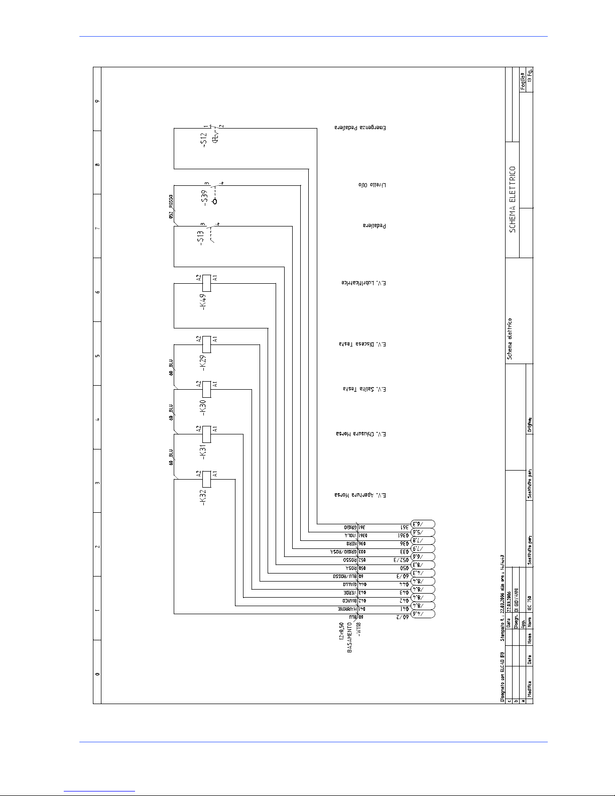
Standardised Wiring Diagrams S20DSP (CENELEC Standard)
S20DSP

6--9
53
Diagrams, exploded views and replace--
S20DSP

6--1054Use and maintenance manual S20DSP
S20DSP

6--11
55
Diagrams, exploded views and replace--
S20DSP

6--1256Use and maintenance manual S20DSP
S20DSP

6--13
57
Diagrams, exploded views and replace--
S20DSP

6--1458Use and maintenance manual S20DSP
S20DSP

6--15
59
Diagrams, exploded views and replace--
S20DSP

6--1660Use and maintenance manual S20DSP
S20DSP
6--17
61
Diagrams, exploded views and replace--
S20DSP

6--1862Use and maintenance manual S20DSP
S20DSP

6--19
63
Diagrams, exploded views and replace--
S20DSP

6--2064Use and maintenance manual S20DSP
S20DSP

6--21
65
Diagrams, exploded views and replace--
IUD/IUV card
Blade guard lim switch
Amperometer trans-
former
Oil level
Speed switch
Blade guard lim. sw.
Vice opening SV
Regenerator solenoid
valve
Vice closing SV
Head lowering SV
Blade motor
Electric pump
Head lifting SV
Bypass solenoid v.
Hydraulic control unit
Handgrip start
Head position
Proximity
M
R
HS
V
N
R
M
031
032
033
034
NC
036
037
038
041
042
043
044
045
046
047
048
049
050
NC
M
B
V
G
Z
RRR
R
S
Blade tension
NC
Wire colour--coding
A -- light blue M -- brown
B--white N--black
C -- orange R -- red
G -- yellowe S -- pink
H -- grey V -- green
L -- blue Z -- purple
114
027
052
025
024
023
022
021
G
S
R
B
G
H
R
R
LR051
052
0Vdc
24 Vdc
LR60
561
0Vdc
24 Vdc
NC
Emergency
01
02
R
R
01
02
R
R
Reset
Min. lubrication
060
061
H
L
R
L
059
58
0Vdc
24 Vdc
GV PE
Inverter start
Inverter start
0 Vdc (inv)
+24Vdc
-- 1 2 V d c
+12Vdc

6--2266Use and maintenance manual S20DSP
Exploded views
This part of the manual contains detailed exploded views of the machine which
can help to gain a deeper knowledge of how it is made.
Motor unit
S20DSP

6--23
67
Code
Description U. of M. Quantity
001.5010 MOTOR WHEEL NR 1,000
010.0355 SELF--LOCKING RING NUT 25X1,5 T NR 1,000
010.0356 SELF--LOCKING RING NUT 45X1,5 S NR 1,000
010.0373 BEARING FIX. RING NUT SH400 --42 NR 1,000
010.2139 GEARBOX SHAFT NR 1,000
010.7111 8X7X32KEY NR 1,000
010.7112 8X7X35KEY NR 1,000
010.7604 0 8 WASHER NR 4,000
010.7605 0 10 WASHER NR 4,000
010.7645 M8 SPRING WASHER NR 4,000
010.7891 TCEI 8 X 16 SCREW NR 4,000
010.7893 TCEI 8 X 20 SCREW NR 4,000
010.7895 TCEI 8 X 30 SCREW NR 9,000
010.7963 TE 8 X 25 SCREW NR 4,000
010.7976 TE 10 X 30 SCREW NR 4,000
019.3621 NR 1,000
022.0212 RAPID JOINT SEM PG 16 NR 1,000
025.0121 REDUCER MVF 63 FCO 1A38 90 B14 NR 1,000
025.0625 MOTOR GASKET SH 310--320--330 NR 1,000
025.0863 CONNECTOR TLK 130 50X80 SH 400 NR 1,000
025.0923 BEARING 3210E--2RS NR 1,000
034.0418 REDUCTOR COVER SH 260 NR 1,000

6--2468Use and maintenance manual S20DSP
Driving pu lley unit
S20DSP

6--25
69
Code
Description U. of M. Quantity
001.4023 REAR BAND GUIDE HEAD SHARK NR 1,000
001.5016 MOTOR WHEEK BOW HEAD SH 452 NR 1,000
007.4828 BOW PIVOTING PIN FEMALE FITTIN NR 1,000
007.4829 BOW PIVOTING PIN MALE FITTING NR 1,000
007.6611 SWIVELING POINT SPACER NR 1,000
007.6631 COUNTERBALANCING PLATE SHARK 4 NR 2,000
007.6635 BRUSH REGULATING PLATE NR 1,000
007.6644 FRONT BLADE HEAD GUIDE BRACKET NR 1,000
007.6645 BRUSH SHAFT FIXING BRACKET NR 1,000
007.6672 BRUSH SHAFT SUPPORT NR 1,000
007.6681 BRUSH SHAFT SHARK 452 NR 1,000
010.0315 SCREW 8.8 10X140 SH 320 NR 1,000
010.0827 RUBBER WHEEL F. CHIP BRUSH NR 1,000
010.0896 HEAD RETURN SPRING SH 400 NR 1,000
010.0902 HEAD FIXED POINT SPRING NR 4,000
010.1201 SCREWS AND BOLTS NR 3,000
010.1580 HEAD RETURN SPRING COVER SH 45 NR 1,000
010.1582 HEAD CYLINDER BRACKET SH 452 NR 1,000
010.1583 EXTERNAL BRACKET CYLINDER SH 4 NR 1,000
010.1704 1 INSERT REAR BAND GUIDE SH N NR 1,000
010.1706 2 INSERTS RAER BAND GUIDE SH N NR 1,000
010.1721 BAND PUSHER SH NR 1,000
010.7230 M10 SELF--LOCKING SCREW NUT NR 1,000
010.7402 6 X 12 CYLIND.POINT VCE GRUB S NR 5,000
010.7470 6 X 35 FLAT POINT VCE GRUB SCR NR 1,000
010.7831 5 X 12 BUTON SCREW NR 5,000
010.7859 TCEI 5 X 12 SCREW NR 3,000
010.7873 TCEI 6 X 30 SCREW NR 2,000
010.7890 TCEI 8 X 12 SCREW NR 2,000
010.7893 TCEI 8 X 20 SCREW NR 4,000
010.7899 TCEI 8 X 60 SCREW NR 4,000
010.7911 TCEI 10 X 20 SCREW NR 1,000
010.7925 TCEI 10 X 40 SCREW NR 4,000
010.7926 TCEI 10 X 45 SCREW NR 2,000
010.7927 TCEI 10 X 60 SCREW NR 1,000
010.7932 TCEI 10 X 110 SCREW NR 2,000
010.7934 TCEI 12 X 50 SCREW NR 2,000
010.8152 M16 NUT NR 1,000
016.0118 REAR BOW HEAD COVER SH 452 NR 1,000
016.0438 REAR BAND GUARD SH 330 HH NR 1,000
016.1196 PNEUMATIC EQUIPMENT CABLING PA NR 1,000
022.0211 RAPID JOINT SEM PG 13,5 NR 1,000
022.0212 RAPID JOINT SEM PG 16 NR 2,000
022.0215 REDUCTION NR 1,000
022.0234 CORD PRESSER NR 1,000
022.0238 CABLE PRESSER PG 7 BS01 NR 2,000
022.0244 LOCK NUT 3217B GREY PG 13,5 NR 1,000
022.0249 POLYAMIDE HUMMEL NUT 1.262.160 NR 1,000
022.2702 NUT PG 7 BL01 NR 2,000
025.0075 BEARING 32009X NR 2,000
025.0088 BEARING 6001 2Z PH 100 NR 2,000
025.0275 NILOS GUARD RING 32009X NR 2,000
025.0555 BAND BRUSH 3103 0 100 SH 400 NR 1,000
025.0802 GRAPHITIZED BUSHING L. 15 DIA NR 1,000
025.0930 BEARING 51100 NR 1,000
028.0130 JOINT 1/4--9 CL 2601 NR 1,000
043.0229 MF 1/4 -- CL 2520 REDUCTION NR 1,000
043.0652 1/4F.M.TAP NR 1,000

6--2670Use and maintenance manual S20DSP
Front flywheel assembly
S20DSP

6--27
71
Code
Description U. of M. Quantity
001.4030 SUPPORT SH 330 CNC FE MOD.1403 NR 1,000
001.4404 BAND TENSION SLIDE SH 452 NR 1,000
001.5009 IDLER WHEEL NR 1,000
001.5015 IDLER WHEEL BOW HEAD SH 452 NR 1,000
007.4822 IDLER WHEEL PIN SH 400 NR 1,000
007.4824 LOCKING PIN SH 400 NR 1,000
007.4891 SLIDE GIB SH 400 NR 2,000
007.5321 BAND TENSION PIN NR 1,000
010.0356 SELF--LOCKING RING NUT 45X1,5 S NR 1,000
010.0915 SPRING 50X18,4X3 SH NR 2,000
010.1517 PROXIMITY FIXING BRACKET SH 40 NR 1,000
010.4021 GIB SLIDE ADJUSTMENT PLATE SH NR 2,000
010.7203 M6 SCREW NUT NR 7,000
010.7461 6 X 25 FLAT POINT VCE GRUB SCR NR 6,000
010.7604 0 8 WASHER NR 4,000
010.7831 5 X 12 BUTON SCREW NR 4,000
010.7878 TCEI 6 X 70 SCREW NR 1,000
010.7893 TCEI 8 X 20 SCREW NR 4,000
010.7894 TCEI 8 X 25 SCREW NR 8,000
016.0117 FRONT BOW HEAD COVER SH 452 NR 1,000
022.0376 CONNECTOR F303N5000 FOR PROXIM NR 1,000
022.0522 PROXIMITY PNP AX NR 1,000
022.2152 ELECTRONIC TENSIONER TRSA/3T.0 NR 1,000
025.0075 BEARING 32009X NR 2,000
025.0275 NILOS GUARD RING 32009X NR 2,000
034.0214 NR 1,000

6--2872Use and maintenance manual S20DSP
Fixed worktable
S20DSP

6--29
73
Code
Description U. of M. Quantity
001.5004 FIXED PLATFORM NR 1,000
001.5011 ROTATING CUTTING TABLE SH452 NR 1,000
001.5012 N.S. UPPER FIXED PLATFORM SH 4 NR 1,000
001.5013 N.S. ROTATING PLATFORM SH 452 NR 1,000
007.4832 JAW LOCKING PIN FOR ROTATING T NR 1,000
007.4833 NR 1,000
007.6624 CLAMPING JAW FOR ROTATING TABL NR 1,000
007.6633 FIXING PLATE F.ROTATING TOWER NR 1,000
007.6637 NR 1,000
007.6651 CLAMPING NUT FOR ROTATING TABL NR 1,000
007.6658 UPPER VICE JAWS BUSHING SH 452 NR 1,000
007.6675 NR 2,000
010.0311 SCREW M12X16 ROTATING TABLE ST NR 3,000
010.0356 SELF--LOCKING RING NUT 45X1,5 S NR 2,000
010.0358 60X2 LOCKNUT F. SHARK 452 NR 2,000
010.0569 N.S. RIGHT FIXED JAW SH 452 NR 1,000
010.0570 RIGHT FIXED IAW SHARK 452 NR 1,000
010.1201 SCREWS AND BOLTS NR 6,000
010.1203 90° OILFILLERDIAM.86X1 NR 1,000
010.1204 M6LUBRICATOR NR 2,000
010.1581 FIX BRACKET FOR SPRING ROTATIN NR 1,000
010.1584 FIXING BRACKET FOR LIMIT SWITC NR 1,000
010.1687 ROTATING TABLE LOCKING SCREW S NR 1,000
010.2023 UPPER VICE SLIDE GUIDE SH 420 NR 2,000
010.3164 HEAD HEAD STROKE STOP NR 1,000
010.7221 M16 LOW SCREW NUT NR 1,000
010.7488 10 X 45 FLAT POINT VCE GRUB SC NR 4,000
010.7602 0 5 WASHER NR 2,000
010.7603 0 6 WASHER NR 2,000
010.7605 0 10 WASHER NR 4,000
010.7641 GROOVER WASHER M12 NR 10,000
010.7645 M8 SPRING WASHER NR 2,000
010.7703 CYLINDRICAL PIN DIAM. 8 X 30 NR 1,000
010.7831 5 X 12 BUTON SCREW NR 2,000
010.7860 TCEI 5 X 15 SCREW NR 2,000
010.7870 TCEI 6 X 16 SCREW NR 20,000
010.7875 TCEI 6 X 40 SCREW NR 1,000
010.7890 TCEI 8 X 12 SCREW NR 2,000
010.7893 TCEI 8 X 20 SCREW NR 3,000
010.7895 TCEI 8 X 30 SCREW NR 2,000
010.7908 TCEI 8 X 50 SCREW NR 4,000
010.7942 TCEI 12 X 40 SCREW NR 2,000
010.7943 TCEI 12 X 45 SCREW NR 10,000
010.7972 TE 16 X 60 SCREW NR 1,000
010.7976 TE 10 X 30 SCREW NR 2,000
010.7978 TE 10 X 40 SCREW NR 4,000
010.8617 NR 2,000
022.0506 LIMIT SWITCH F.FEEDER AX-- AXI NR 1,000
025.0075 BEARING 32009X NR 1,000
025.0275 NILOS GUARD RING 32009X NR 1,000
025.0961 6009 2RS BEARING NR 1,000
034.0211 LOCKING LEVER FOR ROTATING TAB NR 1,000
034.1110 O 30 M6 X 10 HANDWHEEL NR 1,000

6--3074Use and maintenance manual S20DSP
Cutting head cover
S20DSP

6--31
75
Code
Description U. of M. Quantity
001.4022 FRONT BAND GUIDE HEAD SHARK NR 1,000
001.5017 BOW HEAD BEAM SH 452 NR 1,000
001.5018 FRONT BAND GUIDE BRAKET SH 452 NR 1,000
007.4142 PLATE SH 320--330 NR 1,000
007.4831 LOCKING PIN FRONT HEADGUIDE NR 1,000
007.4861 BOW COVER SUPPORT SH 400 NR 1,000
007.6662 FIXING BUSHING SHARK 452 NR 1,000
010.0346 NR 10,000
010.0902 HEAD FIXED POINT SPRING NR 1,000
010.1530 STOP BRACKET SH 400 NR 2,000
010.1705 1 INSERT FRONT BAND GUIDE SH N NR 1,000
010.1707 2 INSERTS FRONT BAND GUIDE SH NR 1,000
010.1721 BAND PUSHER SH NR 1,000
010.2024 UPPER VICE SUPPORT SLIDE GUIDE NR 1,000
010.7226 M6 SELF--LOCKING SCREW NUT NR 2,000
010.7231 M12 SELF--LOCKING SCREW NUT NR 10,000
010.7455 8 X 10 CONICAL POINT VCE GRUB NR 1,000
010.7467 6 X 12 FLAT POINT VCE GRUB SCR NR 5,000
010.7470 6 X 35 FLAT POINT VCE GRUB SCR NR 1,000
010.7480 8 X 30 FLAT POINT VCE GRUB SCR NR 2,000
010.7603 0 6 WASHER NR 1,000
010.7606 0 12 WASHER NR 10,000
010.7831 5 X 12 BUTON SCREW NR 8,000
010.7870 TCEI 6 X 16 SCREW NR 10,000
010.7890 TCEI 8 X 12 SCREW NR 2,000
010.7893 TCEI 8 X 20 SCREW NR 2,000
016.0119 NR 1,000
016.0191 BOW WATER COLLECTOR SH 452 NR 1,000
016.0929 BOW HEAD COVER SH 452 NR 1,000
016.1223 BOW SAFETY SWITCH FIX PLATE SH NR 1,000
016.1224 COVER SAFETY SWITCH FIX PLATE NR 1,000
016.1769 FRONT BAND GUIDE GUARD SH 452 NR 1,000
022.0037 FR 690 SH SAFETY SWITCH NR 1,000
022.0234 CORD PRESSER NR 1,000
025.1152 SLIDE NR 1,000
028.0121 JOINT 3/8--17 CL 2601 NR 1,000
028.0130 JOINT 1/4--9 CL 2601 NR 3,000
034.1107 O 30 M6 X 20 HANDWHEEL NR 1,000
034.1112 O 40 M8 HANDWHEEL X STEEL BASE NR 2,000
043.0229 MF 1/4 -- CL 2520 REDUCTION NR 1,000
043.0652 1/4F.M.TAP NR 1,000

6--3276Use and maintenance manual S20DSP
Cylinders
S20DSP

6--33
77
Code
Description U. of M. Quantity
007.4209 CYLINDER EXTENSION SH 330 HH NR 1,000
010.1103 16 X 1,5 FORK NR 2,000
010.7221 M16 LOW SCREW NUT NR 1,000
022.0046 6639S--001 --202 POTENTIOMETER S NR 1,000
022.0238 CABLE PRESSER PG 7 BS01 NR 1,000
022.2702 NUT PG 7 BL01 NR 1,000
025.0876 JOINT WA 6--6 M M.28 FOR CYLIND NR 1,000
043.0250 M.F. ELBOW 1/4 CL 2020 NR 2,000
043.0340 13X19X1,5--1/4 COPPER WASHER NR 2,000
043.5671 GUARD F.CYLINDER POTENTIOMETER NR 1,000
043.5681 CYLINDER POTENTIOMETER SUPPORT NR 1,000
044.0501 NP 1/4 HYDRAULIC NIPPLE NR 2,000
044.1005 HYDRAULIC CYLINDER SH 280 --320 NR 1,000

6--3478Use and maintenance manual S20DSP
Base assembly
S20DSP

6--35
79
Code
Description U. of M. Quantity
010.1806 NR 1,000
010.7221 M16 LOW SCREW NUT NR 5,000
010.7870 TCEI 6 X 16 SCREW NR 2,000
010.7971 TE 16 X 40 SCREW NR 1,000
013.0181 STEEL BASE SH 452 NR 1,000
016.0190 REAR WATER COLLECTOR NR 1,000
016.1237 NR 1,000
016.1240 VICE CLAMPING LEVER SC--PK 250 NR 1,000
022.0209 RAPID JOINT SEM 29 NR 1,000
022.0212 RAPID JOINT SEM PG 16 NR 2,000
022.0234 CORD PRESSER NR 1,000
022.0244 LOCK NUT 3217B GREY PG 13,5 NR 1,000
022.0247 POLYAMIDE HUMMEL NUT 1.262.290 NR 1,000
022.0249 POLYAMIDE HUMMEL NUT 1.262.160 NR 2,000
022.0324 FAIRLEADS 24 INC.M M.2.5 NR 2,000
028.0010 COOLANT PISTOL SH--TI 8966 NR 1,000
028.0121 JOINT 3/8--17 CL 2601 NR 2,000
028.0231 ELECTROPUMP60/150 220--230--240-- NR 1,000
028.0391 LOOC LINE HOSE SPD ART.69540 3 MT 1,000
028.0396 NOZZLE 0 20 SPD FP50.11B50 NR 1,000
028.0401 FITTING 3/4 SPD FP50.17A20 NR 1,000
034.0901 1/2”GAS. OIL LEVEL CAP NR 1,000
034.0905 TAO/3 1/2” BLACK OIL CAP” NR 1,000
043.0180 REDUCTION M 3/4-- F 3/8 NR 2,000
043.0182 3/4 ELBOW ZINKED JOINT NR 1,000
043.0186 1/2 AQUASTOP FEMALE J OINT NR 1,000
043.0192 RB 9889 JOINT 3/4X20 NR 2,000
043.0223 TE FFF GALVANISED 3/4 JOINT NR 2,000
043.0277 GALVANISED 3/4 CONICAL NIPPLE NR 2,000
043.0351 3/4 GASKET NR 2,000
043.0654 M/F 3/4 CL 6310 TAP NR 1,000

6--3680Use and maintenance manual S20DSP
Control panel
S20DSP

6--37
81
Code
Description U. of M. Quantity
005.2261 ANGLE COUPLING SH AX--AXI--CNC NR 1,000
007.5328 BEARING PIN SH 420 SXI NR 1,000
007.5342 MOVING ROD SUPPORT NR 1,000
007.5461 MOVING ROD WASHER NR 2,000
010.7203 M6 SCREW NUT NR 2,000
010.7681 THICKNESS WASHER DIAM. 12 X 48 NR 1,000
010.7870 TCEI 6 X 16 SCREW NR 4,000
010.7954 TE 6 X 30 SCREW NR 2,000
016.0236 CONSOLLE MOVING ROD NR 1,000
016.0307 CONTROL PANEL NR 1,000
016.1484 CONSOLLE FIX. BRACKET SH 420 S NR 1,000
022.0209 RAPID JOINT SEM 29 NR 1,000
022.0247 POLYAMIDE HUMMEL NUT 1.262.290 NR 1,000
025.0073 BEARING 63001 2RS NR 2,000
031.3235 KEYPAD SH 452 CCS NR 1,000
034.1169 SINGLE TURN ADJUSTMENT KNOB NR 1,000
043.0594 HYDRAULIC REGULATOR SH--CB--T I NR 1,000
044.0170 NR 1,000

6--3882Use and maintenance manual S20DSP
Vice assembly
S20DSP

6--39
83
Code
Description U. of M. Quantity
001.4453 UPPER VICE SUPPORT NR 1,000
001.4457 UPPER VICE NR 1,000
007.4058 ECCENTRIC BUSHING SH 260--280--3 NR 2,000
007.4904 FEEDER LIMIT SWITCH SUPPORT SH NR 1,000
007.5322 CLAMPING BRACKET PIN NR 1,000
007.5421 UNLOCKING PINION NR 1,000
007.5441 MOVING VICE JAW NR 1,000
010.0235 VICE SCREW NR 1,000
010.0918 VICE SCREW NUT RETURN SPRING S NR 1,000
010.1527 BAR LIMIT SWITCH FIX BRACKET S NR 1,000
010.1554 CUTTING VICE CLAMPING BRAKET NR 1,000
010.2372 SCREW NUT 60° NR 1,000
010.7413 8 X 30 CYLIND.POINT VCE GRUB S NR 2,000
010.7454 8 X 8 CONICAL POINT VCE GRUB S NR 1,000
010.7462 8 X 30 CONICAL POINT VCE GRUB NR 2,000
010.7475 8 X 8 FLAT POINT VCE GRUB SCRE NR 1,000
010.7491 10 X 60 FLAT POINT VCE GRUB SC NR 1,000
010.7830 5 X 10 BUTON SCREW NR 2,000
010.7832 BUTON SCREW 6 X 12 NR 3,000
010.7859 TCEI 5 X 12 SCREW NR 4,000
010.7870 TCEI 6 X 16 SCREW NR 8,000
010.7872 TCEI 6 X 25 SCREW NR 28,000
010.7893 TCEI 8 X 20 SCREW NR 1,000
010.7894 TCEI 8 X 25 SCREW NR 7,000
010.7924 TCEI 10 X 30 SCREW NR 2,000
010.8001 TCIC M3 X 16 SCREW NR 2,000
010.9118 NR 2,000
016.1483 CHAIN FIX.PLAT E SH 420 SXI NR 1,000
016.1723 FEEDER LIMIT SWITCH GUARD SH 4 NR 1,000
022.0508 LIMIT SWITCH SH 400 NR 1,000
025.0203 SEAL 35X25X7 NR 2,000
025.0217 O RING 155-- 50,80 NR 1,000
025.0452 ROLLERS 6X6 AISI 420 NR 1,000
025.1152 SLIDE NR 4,000
034.0205 VPRA/125 MR HANDWHEEL SH 282--2 NR 1,000
034.1002 LEVER 10 MA NR 1,000
043.0340 13X19X1,5--1/4 COPPER WASHER NR 3,000
044.0501 NP 1/4 HYDRAULIC NIPPLE NR 2,000
044.1105 AIR CYLINDER SH 420 SXI (SH 40 NR 1,000


7--1
Adjustments
This chapter describes the operations required to adjust the electronic, mechanical and the hydraulic systems. By following these instructions, you can “customise” your machine to suit the type of cut required, thereby optimising cutting
times.
Displaying and editing the set--up parameters
The machine set---up parameters may be programmed directly from the control
console.
" Power up the machine at the main switch located on the left hand side.
" Press simultaneously and in sequence the keys MACHINE PARAMETERS
and MACHINE START;
7

7--2
85
Use and maintenance manual S20DSP
" Once inside the SET---UP menu, use the following three keys to navigate
through the different menu screens:
FCTA Head Downstro-
ke Limit
FCTI Head Upstroke
Limit
“Clear” key
" The FCTA key (Y) allows you to change parameter settings in increments of
one unit.
" The FCTI key (") instead has two functions: it is used to save parameter set-
tings and navigate inside the SET ---UP menu.
" START selection key allows you to zero the current parameter setting.
" The key ”Y--- ” enables the cursor to return to the previous positions.
" To quit the SETUP parameters, press in sequence and simultaneously the
MACHINE PARAMETERS and MACHINE START keys.
Set language parameter
" Press Y to change the display messages presentation language.
ENGLISH
LANGUAGE:
Set parameter for machine type
" Press " to display the parameter for the machine type. Press the Y key to
change machine type; each press of the key corresponds to a different machine configuration.
S20DSP
MACHINE MOD.:
Semiautomatic--Dynamic and Manual operation setting (optional)
" Inthisvideopageitispossibletoconfigurethepossiblepresenceofoptional
operating cycles, such as the Manual and Semiautomatic--- Dynamic cycle.
Pressing the key " go to the item of this parameter, then with the Y key
choose YES or NO.
NO
MAN&SAD CYCLE:

7--3
86
Adjustments
Pedal control setting (optional)
" Press " to display the pedal control parameter, then press Y to set the pres-
ence (YES) or the absence (NO) of this optional.
NO
PEDAL START
Optional inverter presence settings
" Press " to display the inverter parameter and then press Y to set the pres-
ence or absence of this optional device by selecting ”yes” or ”no”.
YES
INVERTER:
Blade speed proximity settings
" Press " to display the band speed detection proximity parameter, then press
Y to set the presence or the absence of this optional, choosing YES or NO.
NO
BLADE SPEED PROXY:
Minimal lubrication system settings
" Press " to display the min. lubrication system parameter, then press Y to set
the presence or the absence of this optional, choosing YES or NO.
NO
MIN. LUBR.:
FCTI / FCTA digital output enabling setting
" Press the " key to display the parameter enabling or disabling the outputs of
the positions FCTI (backward head limit switch) and FCTA (forward head
limit switch). Press the Y key to set YES or NO.
NO
FCTI/A OUTPUTS
Blade stop setting
" Press the " key to display the blade stop parameter, then press Y to set the
value of this parameter.
If the value is set as 2, the blade never stops;
if it is set as 1, the blade stops in the FCTI (backward head limit switch)
point;

7--4
87
Use and maintenance manual S20DSP
ifthevaluesissetas0,thebladestopsintheFCTA(forwardheadlimit
switch) point.
NEVER/FCTI/FCTA: 0
BLADE MOTOR OFF
Cutting vice opening setting
" Press the " key to display the parameter indicating if the shearing vice must
open when the head is in the FCTI (backward head limit switch) point or in
the FCTA (forward head limit switch) point; press Y to se t the value as 0
(vice opening in FCTA), or as 1 (vice opening in FCTI).
FCTA/FCTI: 1
CUTTING VICE OPENING
Cutting vice opening/closing time setting
" Press the " key to display the parameter indicating the time between the vice
closing and the cut start and between the cut end and the vice re ---opening.
Press Y to change this value, ranging between 0.0 and 9.9 seconds.
TIME = 0.0
VICE OPENING/CLOSING
Machine maximum power input setting
" Press the " key to display the parameter and then increase or reduce the
value with the Y key.
BLADE = 00.0
MOTOR I MAX
The factory set values are relative to the motor installed on the machine.
Measurement unit setting
" Press the " key to display the parameter, then press Y to set the value as 0
or 1, to choose the measurement unit expressed respectively in pounds or
kilograms.
FIPS/MKS = 0
MEASUREMENT UNIT
N.B.

7--5
88
Adjustments
Setting minimum blade tensioning
The machine will enter emergency mode if the band is not tensioned correctly.
This parameter allows to set the minimum blade tension threshold (Kg 600);
TIGHTENING = 0600
MIN. BLADE
Display backlig h t ing time setting
" Press the " key to display the LCD backlighting time parameter, then press
the Y and " keys to set the time expressed in minutes.
TIME = 10
LCD BACKLIGHTING
Cutting head stroke
The cutting head crosses the space between the forward and backward position
definable in the SET---UP with the CUTTING HEAD POSITION parameter. A
value between 000 and 300 must be set. Check that the bow, really and not
virtually, crosses the amplitude of the cut between the structural limits of cutting
head backward end run and cutting head forward end run. The scope of adjustment is to set the value of the real cutting head position both at FCTI (backward
limit 275÷300) and at F CTA (forward limit 008÷012). Two adjustments are
performed to obtain this result: one on the cutting head cylinder and the other on
the IUD/IUV layout of the M30 controller. Operation sequences:
" Power the machine rotating the main switch on the left side of the console;
" Press simultaneously and in sequence the keys MACHINE PARAMETERS
and MACHINE START;
" Press the RESET.
" scroll the machine parameters with the key indicated in the figure till reach-
ing the following video page:
HEAD POSITION = 150
FCTI/FCTA LIMIT

7--6
89
Use and maintenance manual S20DSP
" Press in sequence and simultaneously the â key and the key for the head
lowering (Y---), position the bow completely downwards;
The down position must have a value ranging between 008 and 012, otherwise
operate as follows:
" Remove the fixing screws from the black box on the cylinder using a hex
wrench.
" Remove the box protecting the potentiometer, taking care not to tug at the
connection cables.
" Using an Allen key, slacken the grub screws fixing the rod and free the poten-
tiometer body.
" Manually rotate the potentiometer body until the display readout is between
008÷012.

7--7
90
Adjustments
HEAD POSITION = 010
FCTI/FCTA LIMIT
" Lock the potentiometer support in place using the grub s crew. Close the cyl-
inder box and tighten down the screws.
" Press the ⇑ and FCTA keys in sequence and simultaneously.
" Set the FCTI point, taking the head completely backwards pressing in se-
quence and simultaneously the ⇑ key and the key for the head lifting (Y+).
" Open the control board removing the frame and pull the keyboard out of the
console;
" Identify the board IUD/IUV of the controller M30 to adjust the potentio-
meter indicated by the arrow in the following image:

7--8
91
Use and maintenance manual S20DSP
" Three potentiometers are mounted on the IUD/IUV card. Adjust the adjust-
ment screw of the potentiometer indicated by the arrow by a screw---driver at
a value of 275÷300; the obtained variation is displayed on the machine.
HEAD POSITION = 280
FCTI/FCTA LIMIT
" Press simultaneously and in sequence the keys SET--- UP and ON to quit the
SETUP parameters:
" Test to make sure it is functioning correctly.
Software version and total use time of the machine
" This parameter indicates the installed software version and the total working
time of the machine.
TT = 0000:00
M30 v01.01 00--05
Adjusting the display brightness
If external factors like changing ambient lighting conditions in the machine
installation site, affect visibility, adjust the brightness of the control and programming console display. This is very important since the operator must be able to
clearly read the display messages at all times.
" To adjust the brightness, first remove the screws fixing the front console
panel. The photo below illustrates the M30 controller card on which the
brightness potentiometer is marked by an arrow.
" Using a screwdriver, rotate the potentiometer until the required display
brightness is obtained.

7--9
92
Adjustments
Machine working pressures
This section describes the procedures to change the vice and head operating
pressures. Both adjustments strongly depend on the material type being processed.
Thevicelockingpressurecanbesetifthematerialcouldbestrainedorcouldbe
quite unstable while cutting.
The head lowering speed can be set by a flow adjuster on the control console.
Hydraulic pressure
Both vice and head pressures can be adjusted by the power packs.
Both the pneumatic and hydraulic vices have a maximum travel of 8 mm. This
means that after positioning the workpiece on the work table and before starting the cycle, the moving jaw must be positioned to within 2÷3mmofthe
workpiece as previously described in Chapter 5.
The operating pressures (shearing vice and cutting head) can be adjusted by the
max. pressure adjusting valve.
" Open the door of the machine base, remove the fastening screws and pull out
the power pack from inside the base.
" Slacken the hex nut on the relief valve, and using an Allen key, increase
(clockwise) or reduce (counter---clockwise) the pressure reading on the pressure gauge.
" This done, tighten the lock nut and return the hydraulic power pack back in-
side the base.
Warning

7--1093Use and maintenance manual S20DSP
Cutting head
Blade tension er slide p lay adjustment
To reduce the play which may develop over time between the blade tensioner
slide and slide gibs, adjust the grub screws between the gibs and slide as follows:
" open the cutting head cover;
" un ---tension the band with the relevant hand---wheel:
" remove the blade from the flywheels;
" remove the plug connecting the slideway to the cylinder rod;
" move the slide back and forwards to locate any friction or excessive play;
" slacken the nuts, using a tubular nut driver to hold the grub screws firm;
" finally, tighten the grub screws to take up any play or otherwise, slacken them
to reduce any friction.
 Loading...