

Hyd-Mech S-20DS Use And Maintenance Manual
EN
YEAR OF MANUFACTURE: ______________
S--20DS
USE AND MAINTENANCE MANUAL


Introduction and technical specifications 1---1......................
Foreword 1---1..........................................................
Machine presentation 1--- 2...............................................
Machine specification 1--- 2...............................................
Dimensions 1 ---5........................................................
F u n c ti o n a l p a rt s 2 --- 1............................................
S --- 2 0D S m o d e l 2 --- 1.....................................................
Cutting head 2---2.......................................................
Vice 2 --- 3..............................................................
C o n t ro l P a n e l 2 --- 3......................................................
Tu r nt a bl e 2 --- 4..........................................................
F i x e d p l a t f o r m 2 --- 4.....................................................
M o t i o n --- v a r i a t o r --- r e d u ce r u n i t 2 --- 5.......................................
Base 2 --- 6..............................................................
Safety and accident prevention 3---1................................
U s e o f t h e m a c h i n e 3 --- 1.................................................
General recommendatio ns 3---2...........................................
Recommendations to the operator 3---3....................................
Machine safety devices 3---5..............................................
Reference standards 3---5................................................
Protection against accidental contact with the blade 3---5......................
Electrical equipment 3---6................................................
Emergency devices 3 ---7..................................................
Noise level of the machine 3---8...........................................
Noise level measurement 3---8............................................
Noise level values 3---8...................................................
Electromagnetic compatibility 3---9........................................
Machine installation 4 ---1........................................
Packaging and storage 4---1...............................................
Anchoring the machine 4--- 4..............................................
Minimum requirements 4--- 4..............................................
C h e c k l i st 4 --- 5..........................................................
Connection to t he power supply 4 ---6.......................................
Description of machine operation 5---1.............................
Control panel description 5---1............................................
Basic instructions for carrying out a cutting operation cycle 5---3................
Clamping the work piece in the vice 5--- 3...................................
Rapid vice positioning 5--- 4...............................................
R a p i d v i c e t r a n s l a t i o n 5 --- 4...............................................
Wi d t h o f c ut 5 --- 5.......................................................
Preliminary check list for cutting operation 5--- 6.............................
CCS (Cut Control System) functioning cycle 5---6............................
Execution of inclined cuts 5---8............................................
Loading side rollerway position 5--- 8.......................................
Angled cuts 45˚ to the left 5---9...........................................
Angled cuts 60˚ to the left 5---10...........................................
Angled cuts 45˚ to the right 5--- 12..........................................
Angled cuts 60˚ to the right 5--- 13..........................................
Diagrams, exploded views and replacement parts 6---1................
Pneumatic diagram (MA version) 6---1.....................................

How to read the wiring diagrams 6---2......................................
D2 --- Letter codes used to designate the type of component 6---4...............
Standardised Wiring Diagrams (CENELEC Standard) 6---7...................
Exploded views 6---16.....................................................
Base assembly 6---16......................................................
F i x e d w o r k t a b l e 6 --- 1 8....................................................
Front flywheel assembly 6 ---20..............................................
Vi c e u n i t 6 --- 2 2..........................................................
Driving pulley unit 6--- 24..................................................
Cutting head cover 6---26..................................................
M o t o r u n i t 6 --- 2 8.........................................................
C y l i nd e r s 6 --- 3 0..........................................................
C o n t ro l p a n e l 6 --- 3 2......................................................
C y l i nd e r s S --- 2 0D S 6 --- 3 4.................................................
O pt i o n a l M A 6 --- 3 6......................................................
OptionalDischargesideadaptor 6---38......................................
OptionalDischargesideadaptor 6---40......................................
A d j u s t m e n t s 7 --- 1...............................................
Air treatment unit (MA version) 7---1......................................
Topping up and bleeding the cylinder 7---2..................................
Topping up the he ad cylinder 7--- 2.........................................
Bleeding the head cylinder 7---3...........................................
Working pressure of the hydraulic control unit (optional) 7---4.................
Cutting head 7---5.......................................................
Blade tensioner slide play adjustment 7---5..................................
Adjusting operating head travel (CCS) 7---6.................................
Adjustment of the operating head course (with optional hydraulic control unit
for the raising of the cutting bow) 7---7..................................
B la d e g u i d e c o m p o n e n t s 7 --- 9.............................................
Blade guide heads 7---9..................................................
Blade steady buttons 7---9................................................
Blade guide plates 7---9..................................................
Blade 7 --- 1 2.............................................................
Tool changeover 7--- 12....................................................
Blade perpendicularity 7--- 14..............................................
Blade orthogonality 7---15.................................................
Front flywheel 7---16......................................................
Rear flywheel 7---16......................................................
Maintenance and choice of consumables 8---1.......................
The role of the operator 8---1.............................................
Maintenance requirements 8---2...........................................
General maintenance 8 ---2...............................................
Daily 8 --- 2.............................................................
Weekly 8 --- 2............................................................
Monthly 8---3...........................................................
Maintenance of working parts 8 ---3........................................
Consumable materials 8 --- 3...............................................
Oils for oleopneumatic circuit 8---3........................................
Oil for lubricant/coolant fluid 8---4.........................................
Cutting speed and choice of tools 9---1..............................
Cutting speed 9---1......................................................
Standard machine 9--- 1..................................................

Choice of blade 9--- 2....................................................
Saw tooth pitch 9--- 2.....................................................
Cutting speed and downstroke speed 9---2..................................
Ty p e s o f s w a r f : 9 --- 3.....................................................
Lubricant/coolant fluid 9---4..............................................
Blade structure 9---4.....................................................
B la d e t y p e s 9 --- 5........................................................
C o n v e n t i o n a l r a k e 9 --- 5..................................................
Po s i t i v e r a k e 9 --- 5.......................................................
Va r i a b le p i t c h 9 --- 5......................................................
Variable pitch blades with 0˚ cutting angle 9--- 6..............................
Variable pitch with positive rake (from 9 to 10 degrees) 9--- 6...................
Set: 9 --- 6...............................................................
Standard or splayed set 9--- 6..............................................
U n d u l a t e d s e t 9 --- 7......................................................
Alternating grouped sets 9---7.............................................
A l t e r n a t i n g s e t 9 --- 7.....................................................
Blade selection table relating to cutting speed and downstroke speed 9---8.......
Classification of steels 9--- 9...............................................
Classification of steels 9--- 10...............................................
Troubleshooting 10---1............................................
Troubleshooting blade and cutting problems 10---1............................
Troubleshooting machine faults 10---8.......................................
Accessory Installation 11---1.......................................
Accessories that can be fitted by the user 11--- 1...............................
Blade 1 1 --- 1.............................................................
Can of emulsible oil 11---1.................................................
Motorchipdischargerunit 11---1...........................................
Minimal lubrication system 11---1...........................................


1--1
Introduction and
technical
specifications
Foreword
Hyd---Mech, in response to modern production techniques, has developed the
new S---20DS.
This work tool has been designed to satisfy the wide range of cutting needs of a
modern workshop with simplicity and reliability, while at the same time complying with all EEC safety standards.
The S---20DS is structurally rigid, silent and safe: it produces a minimum of waste
while its great versatility makes it suitable for cutting various materials such as
stainless steel light alloys, aluminium, copper and bronze at high speed and with
high precision.
Its high cutting capacity, combined with the possibility of making inclined cuts
from 60˚ left to 60˚ right, make this model the ideal solution for satisfying the
wide strange of cutting needs of machine shops, turneries, structural steel shops
and engineering workshops.
We congratulate our clients on having chosen this product, which will give
effective and faithful service for many years, especially if the instructions
contained in this use and maintenance manual are carefully followed.
This band saw has been exclusively designed to cut metals.
Warning
1
1--2
2
Use and maintenance manual S --20DS
Machine presentation
This machine is equipped with CCS (Cut Control System), which is a devicethat
consents a cut for each bow fall,with controlled descent speed: after having
positioned the head in the initial cutting point, the operator fastens the material
in the vice and presses the start button on the control board to start the band up.
The band begins to rotate and the head begins to descend. Its speed is adjustable
using the head descent speed adjuster positioned on the control board.
The head determines cutting of the material. Once the cut has been made, an end
run stops the cutting cycle, after which the head is raised manually ( or with the
optional hydraulic control unit for raising of the head).
After having fed the material again a new cutting cycle can be started by pressing
the button on the control board. In the AV version (Automatic Vice) a pneumatic
cylinder applied to the vice blocks the material in the jaws: the vice opening/closing key is found on the control board.
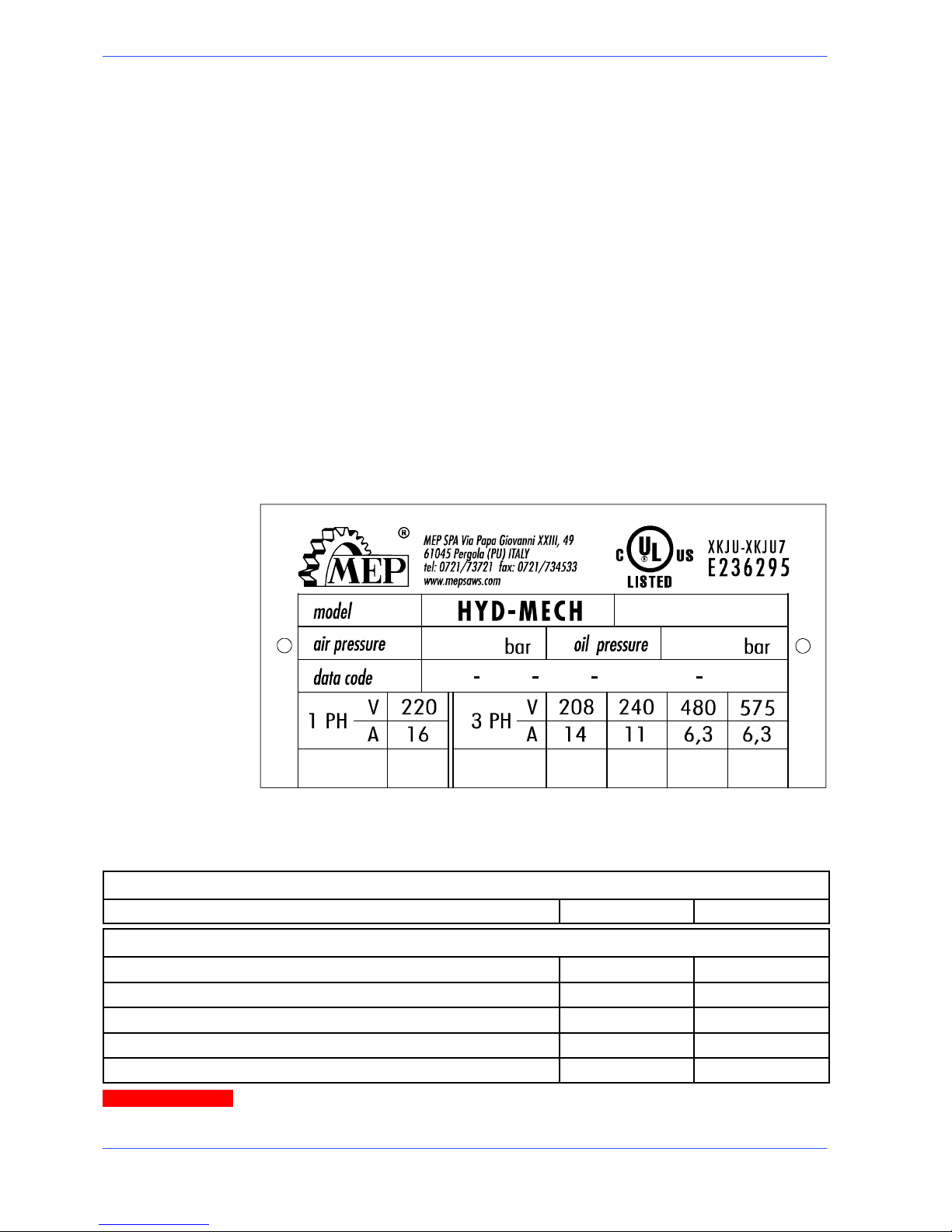
Machine specification
Theanodisedaluminiumnameplateisrivetedonthesideofthemachine;the
same data are reproduced on the declaration of conformity included with this use
and maintenance manual.
When communicating with the Technical Service department, the model, serial
number and year of manufacture of the machine must be quoted.
CUTTING SPEEDS
Blade rotation speed mt/min
20 100
BAND SAW
Rated size mm
4500 x 27 x 0,9
Max/min blade length mm
4500 ± 40
Blade height mm
27
Blade width mm
0,9
Band saw tension Kg
1250
When choosing the cutting tool, if its dimensions do not correspond to those
included in the ”Rated size” section, check that the dimensions at least fall
within the admissible max/min specifications.
N.B.
Attention
1--3
3
Introduction and technical specifications
RATED ELECTRICAL POWER
Head spindle motor KW 1,5
Electric coolant pump motor KW 0,1
M1 power pack motor (optional) KW
0,37
Max installed power KW 1,97
WORKING PRESSURE
Working pressure blade tensioning/detensioning
Kg
1250/900
Head working pressure in the ascent phase (optional) Bar 20
Vice working pressure during opening/closure phase (AV ver-
sion)
Bar 6
LUBRICANT/COOLANT FLUID AND OIL
Oil for blade t ensioner unit (optional) capacità Lt 8,5
Lubricant/coolant fluid (oil concentration 5--- 6%) capacità Lt 200
VICE
Vice max . opening mm 460
SPINDLE MOTOR
No.of poles Current (Volts) Absorption
(Amps)
Power (Kw) rpm
4 400 3,7 1,5 1410
Stator wound with enamelled copper wire, class H 200˚C.
Class F insulation (limit temperature TL 155˚C).
IP 55 protection rating (total against contact with live parts, water sprayed from all directions, with shaft oil
seal).
Conforming to CEI norms, publication: IEC 34 of 01/07/1985.
Example of class F insulation: in air--cooled machines at an ambient temperature of 40˚ C (according to CEI 2--3 and IEC 85), the allowable overtemperature is 100˚ C (where 100
C represents the allowable DT).
ELECTROPUMP MOTOR
Single phase; Frequency 50 Hz.
Voltage ( Vo l t s ) Absorption
(Amps)
Power (Kw) rpm Delivery rate
lt/min
Head (mt. )
230 0,30 0,09 2800 24 1,5
400 0,18 0,09 2800 24 1,5
Protection rating IP 55.
Conforming to CEI norms, publication: IEC 34 of 01/07/1985.
CUTTING CAPACITY
Section
0˚ 330 330 450x330
45˚ a 320 300 300x300
N.B.

1--4
4
Use and maintenance manual S --20DS
CUTTING CAPACITY
60˚ a 210 200 200x250
45˚ ' 320 300 300x300
60˚ ' 210 200 200x250
CUTTING CAPACITY
Section
Ø
lxl
bxh
0˚ 260 230 290 x 200
45˚ a 190 180 180 x 210
60˚ a 120 120 120 x 130
45˚ ' 150 130 120 x 160

1--5
5
Introduction and technical specifications
Dimensions
MACHINE INSTALLED
Work t a ble he i g h t mm 880
Weight Kg 1080
2300
1880
70
1700
2450
3300
880
1--6
6
Use and maintenance manual S --20DS
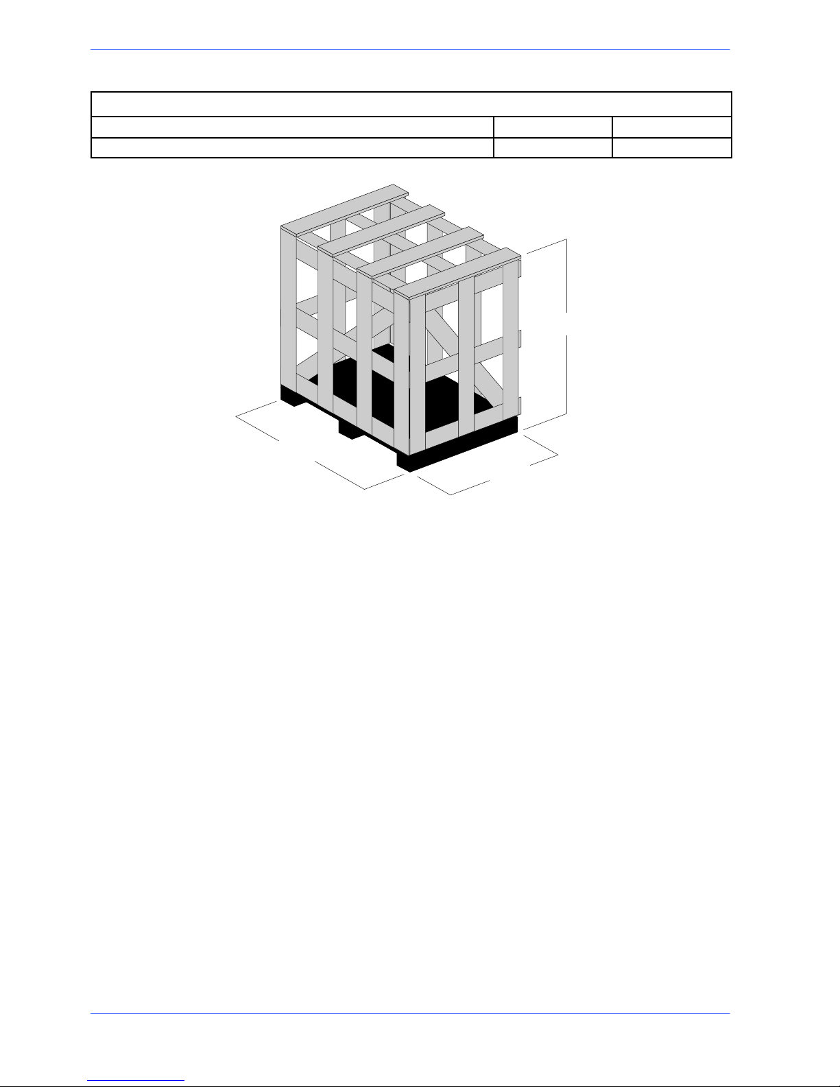
PAC KED WEIGHT
Wooden cage and pallet Kg 130
Wooden pallet Kg 70
2900
1800
1800
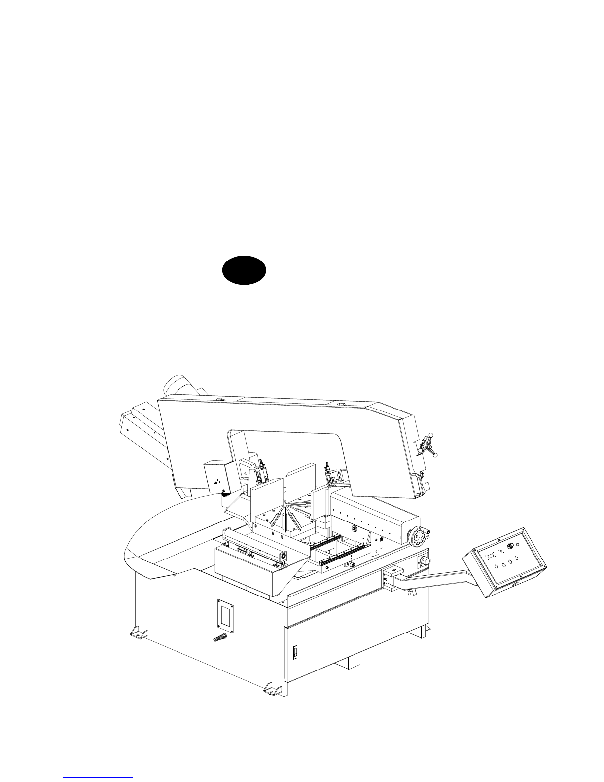
2--1
Functional parts
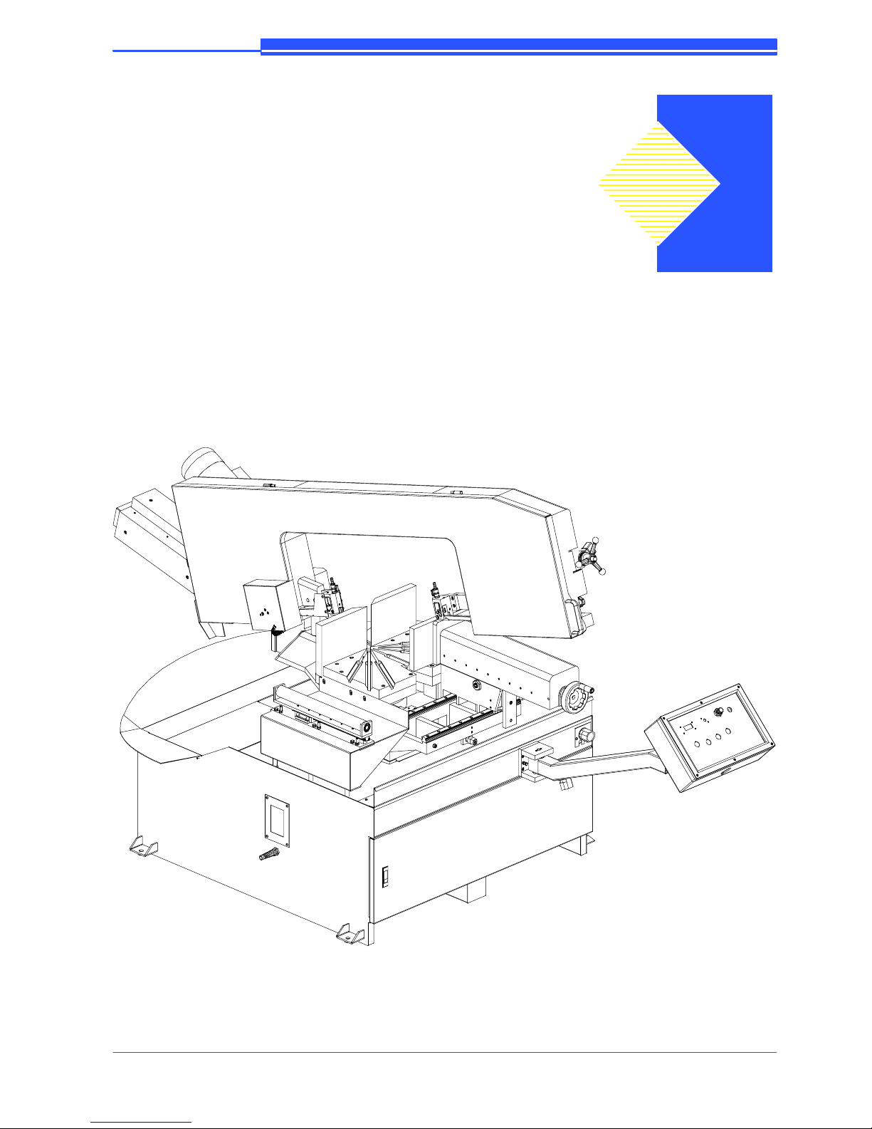
S--20DS model
In order for the user to move towards a full understanding of how the machine
works, which is described in detail in the chapter 5, this chapter deals with the
main units and their locations.
CUTTING HEAD
CONTROL
PANEL
VICE
TURNTABLE
BASE
2
2--2
8
Use and maintenance manual S --20DS
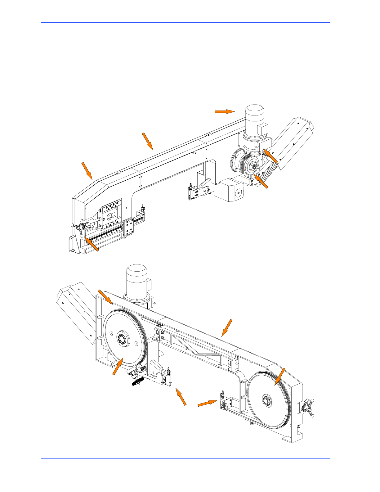
Cutting head
The oerating head is the element that performs the cut and is made up of a bow
made from a fusion of cast iron onto which the band, the band guide elements,
the band tensioning unit and the mechanical speed variator are mounted. The
operating head is restricted in its movements by the articulated joint on the
rotatng platform.
Motor
Blade guide heads
Belt tensioning wheel
Transmission box
Drive pulley
Idle pulley
Rear flywheel
Speed variator
Cutting head beam
Front flywheel
Blade casing
2--3
9
Functional parts
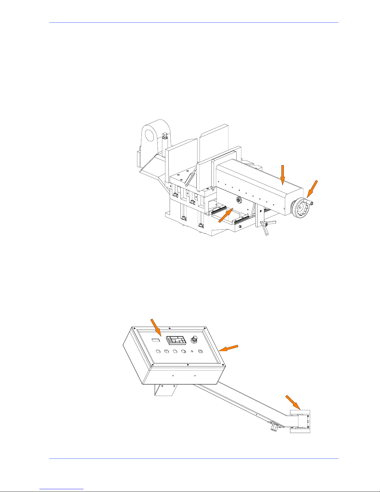
Vice
The vice is the unit that clamps the workpiece during cutting. It consists of a vice
support, commonly known as a “lead nut”, fixed to the work table, and a lead
screw with a sliding support on which the mobile jaw is mounted. It can run
transversely with respect to the cutting surface, or lengthways, for opening and
closing, on the linear guides and slides with recirculation of pre---loaded spheres.
Theviceismanuallynearedtothematerialtobecutusingahand---wheeland
blocking is performed using a hydraulic cylinder (in the AV version).
Slideway
Handwheel
Vice support (lead nut)
Control Panel
The control panel has a protection rating of IP 54 and contains the electronic
equipment. Access to the control panel is protected by a safety panel mounted on
hinges and fastened with screws, specially designed to prevent tampering. The
control panel swivels on two articulated joints so that it can be positioned by the
operator for greater ease---of---use and safety.
Control panel
Articulated joints
Control console
2--4
10
Use and maintenance manual S --20DS
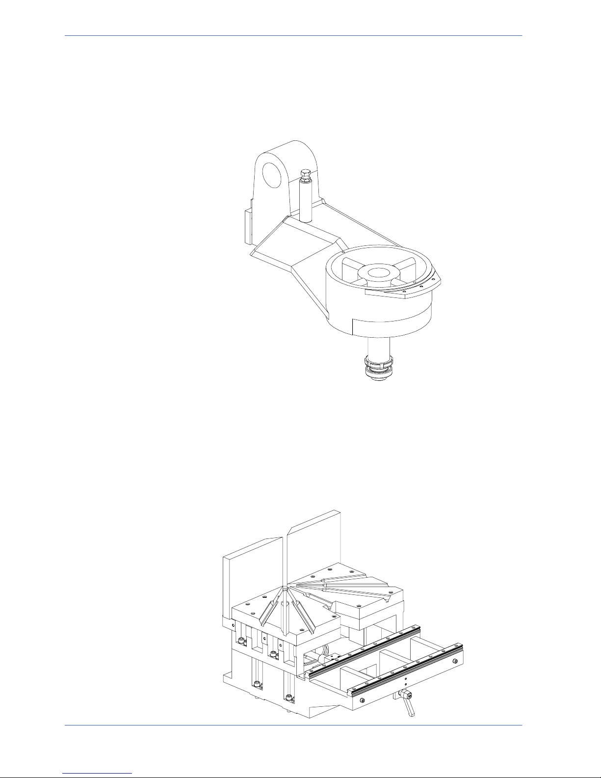
Turntable
Made from a fusion of cast iron it makes up the fulcrum of the cutting band. By
releasing the blocking lever on the fixed platform right and left rotation of the
bow is consented.
Fixed platform
It is made up of two parts, upper and lower, which close the rotating and platform
and support the cutting surface in interchangeable steel. The lower part is the
resting base of the rotating platform, cutting surface and vice. It is free to run
transversely on linear guides and slides with re ---circulation of pre ---loaded
spheres. It is integral to the base and the rear part has the reference strokes for
60˚ left and 60˚ right cuts.
2--5
11
Functional parts
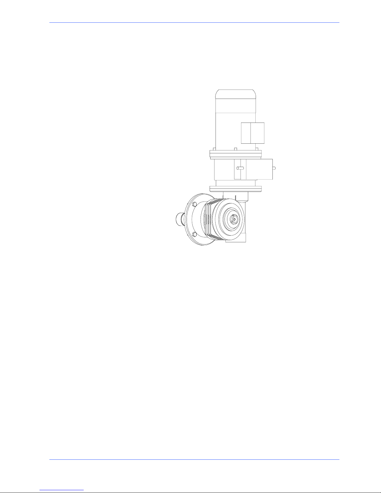
Motion--variator--reducer unit
Rotation of the band is performed by a system made up of a motor connected to a
variator and a mechanical speed reducer. This unit allows rotation of the band in
a continuous adjustment range that goes from 20 to 100 m/min.
2--6
12
Use and maintenance manual S --20DS
Base
This unit features a large coolant collection surface which conveys the coolant to
the rear tank via the tank cover, and a swarf collection drawer. An electric pump
is housed inside the tank which draws the clean fluid from the filter system.
Lubricant/coolant tank
Electric pump housing
Swarf collection drawer
Hydraulic single box housing

3--1
Safety and accident
prevention
The S---20DS has been designed and produced in accordance with European
standards. Forthecorrectuseofthemachinewerecommendthattheinstructions contained in this chapter are carefully followed.
Use of the machine
The S---20DS band saw cutting machine is intended exclusively for cutting
metallic materials, ferrous or non---ferrous, in section or solid.
Other types of material and machining are not compatible with the s pecific
characteristics of the saw.
The employer is responsible for instructing the personnel who, in turn, are
obliged to inform the operator of any accident risks, safety devices, noise
emission and accident prevention regulations provided for by international
standards and national laws regarding the use of the machine. The operator must
be perfectly aware of the position and function of all the machine’s controls.The
instructions, warnings and accident prevention standards in this manual must be
respected without question by all those concerned.The following definitions are
those provided for by EEC MACHINES DIRECTIVE 98/37/CE :
H “Danger zone”: any zone in and/or around a machine in which the presence of a
person constitutes a risk for the safety and health of that person.
H “Person exposed”: any person finding himself either completely or partly in a
danger zone.
H “Operator”: the person or persons given the responsibility of installing, operating,
adjusting, maintaining, cleaning, repairing or transporting the machine.
The manufacturer declines any responsibility whatsoever, either civil or criminal, should there be unauthorised interference or replacement of one or more
parts or assemblies on the machine, or if accessories, tools and consumable
materials are used that are different from those recommended by the manufacturer itself or if the machine is employed in a plant system and its proper
function is thereby altered.
Attention
3
3--2
14
Use and maintenance manual S --20DS
General recommendations
LIGHTING
Insufficient lighting for the types of operation envisaged could constitute a safety
hazard for the persons concerned. For this reason, the machine user must provide
lighting in the working area sufficient to eliminate all shadowy areas while also
avoiding any blinding light concentrations. (Reference standard ISO 8995 ---89
“Lighting in work environments”).
CONNECTIONS
Check that the power supply cables and pneumatic feed systems comply with the
maximum machine absorption values listed in the “Machine Specification” tables;
replace if necessary.
EARTHING
The installation of the earthing system must comply with the requirements set out
in IEC STANDARD 204.
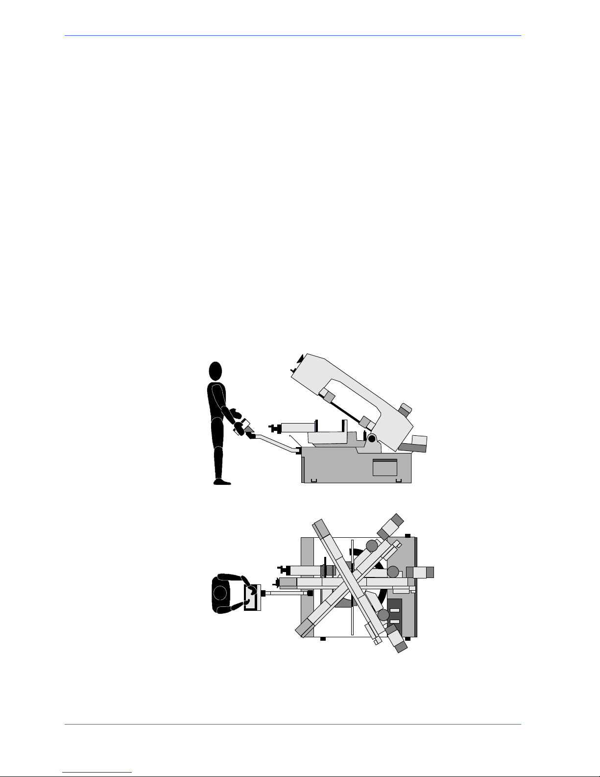
OPERATOR POSITION
The position of the operator controlling machine operations must be as shown in
the diagram below.
3--3
15
Safety and accident prevention
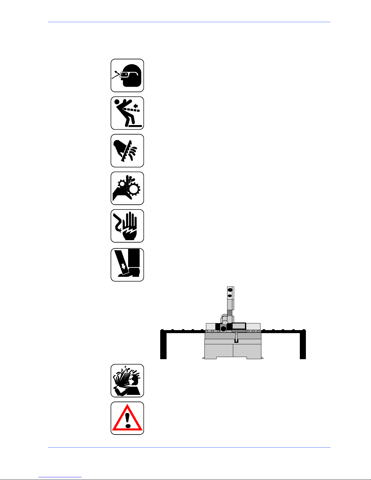
Recommendations to the operator
Always wear proper goggles or protective glasses.
Do not use the machine without the guards in position.
Do not allow ha nds or arms to encroach on the cutting zone while the
machine is in operation.
Do not wear oversize clothing with long sleeves, oversize gloves, bracelets, necklaces or any other object that may become entangled in the machine duri ng working; long hair must be tied back and bunched.
Alwaysdisconnectthepowersupplytothemachinebeforecarryingout
any maintenance work whatsoever, including in the case of abnormal
operation of the machine.
Before starting cutting operations, support the materia l at both ends of
the machine using the support arm --- standard, or OPTIONAL accessories such as the feed and discharge roller tables shown in the diagram
below. Before removing the devices supporting and moving the material,
fasten the latter in place using the machine’s clamping devices or other
suitable equipment.
mm. 1500
mm. 1500
FEED ROLLER TABLE DISCHARGE ROLLER TABLE
Any maintenance work on the hydraulic or pneumatic systems must be
carried out only after the pressure in the system has been released.
The o perator must not perform any risky operat ions or operations not
required for the machining operation under way (e.g. remove swarf or
metal shavings from the machine while cutting).
3--4
16
Use and maintenance manual S --20DS
Remove equipment, tools or any other objects from the cutting zone; always keep the working area as clean as possible.
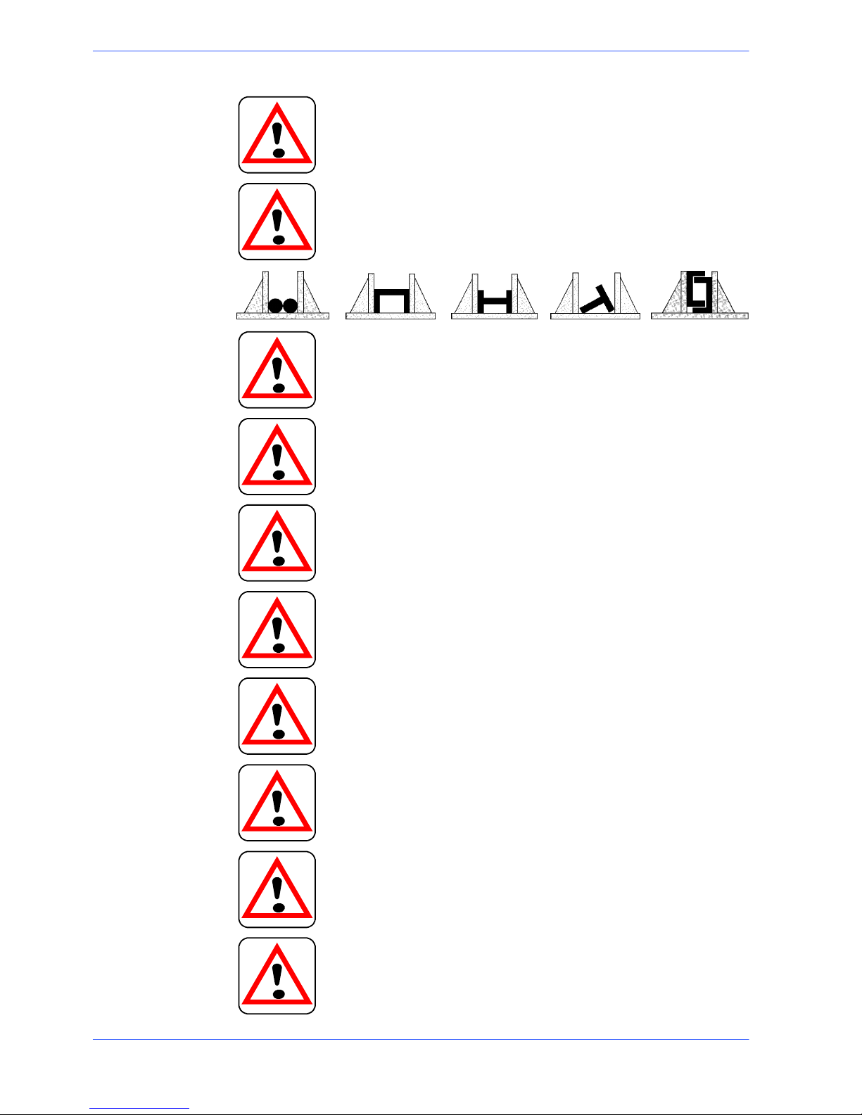
Before starting any cutting operations, ensure that the workpiece is securely held in the vice and the machine has been set correctly. A number of
examples of how to clamp different profiles correctly in our machines are
shown below.
Do not use the machine to cut pieces that exceed the capacity of the machine as listed in the machine specifications.
Never move the machine while it is cutting.
Do not use blades of different sizes to those recommended in the machine specifications.
When cutting very short pieces, make sure that they are not dragged behind the support shoulder, where they could jam in the blade.
When using the pneumatic vice (MA version) check that the jaws move
right up to and effectively clamp the workpiece, as the maximum travel is
only 8 mm, and check that the clamping procedure is correct.
When working on the band saw, wear gloves only when handling materials and for tool changing or adjustment operations. Only perform one
operation at a time and do not hold more than one item or operate more
than one device simultaneously. Keep hands as clean as possible.
Warning: if the blade jams in the cut, press the emergency stop push--button immediately. If this does not free the blade, slowly loosen the
vice, remove the piece and check the blade or blade teeth for breakage.
Replace the blade if necessary.
Before carrying out any repair work on the machine, consult the Technical Assistance Service: this can be done through a representative in the
country of use of the machine.

3--5
17
Safety and accident prevention
Machine safety devices
This use and maintenance manual is not intended as purely a guide for the use of
the machine in a strictly productive environment, it is instead an instrument
providing information on how to use the machine correctly and safely. The
following standards are those specified by the EEC Committee in the directives
regarding safety of machinery, health and safety at work, personal protection and
safeguarding of the environment. These standards have been applied to the
S---20DS band saw.
Reference standards
MACHINE SAFETY
H EEC MACHINES DIRECTIVE 98/37/CE ;
H EEC directive no. 89/336 ”EMC -- Electromagnetic Compatibility”;
H EEC Directive No. 73/23 known as ”Low voltage directive”.
HEALTH AND SAFETY AT WORK
H EEC Directive No. 80/1107; 83/477;86/188;88/188; 88/642 for the protection of
workers against risks caused by exposure to physical, chemical and biological agents during working;
H EEC Directive No. 89/391 and Special EEC Directives No. 89/654 and No. 89/655
for improvements in health and safety at work;
H EEC Directive No. 90/394 for the protection of workers against risks deriving from
exposure at work to carcinogenic substances;
H EEC Directive No. 77/576 and No. 79/640 on safety signs at work.
PERSONAL PROTECTION
H EEC Directive No. 89/656 and No. 89/686 on the use of personal protection de-
vices.
ENVIRONMENTAL PROTECTION
H EEC Directive No. 75/442 on waste disposal;
H EEC Directive No. 75/439 on the disposal of used oil.
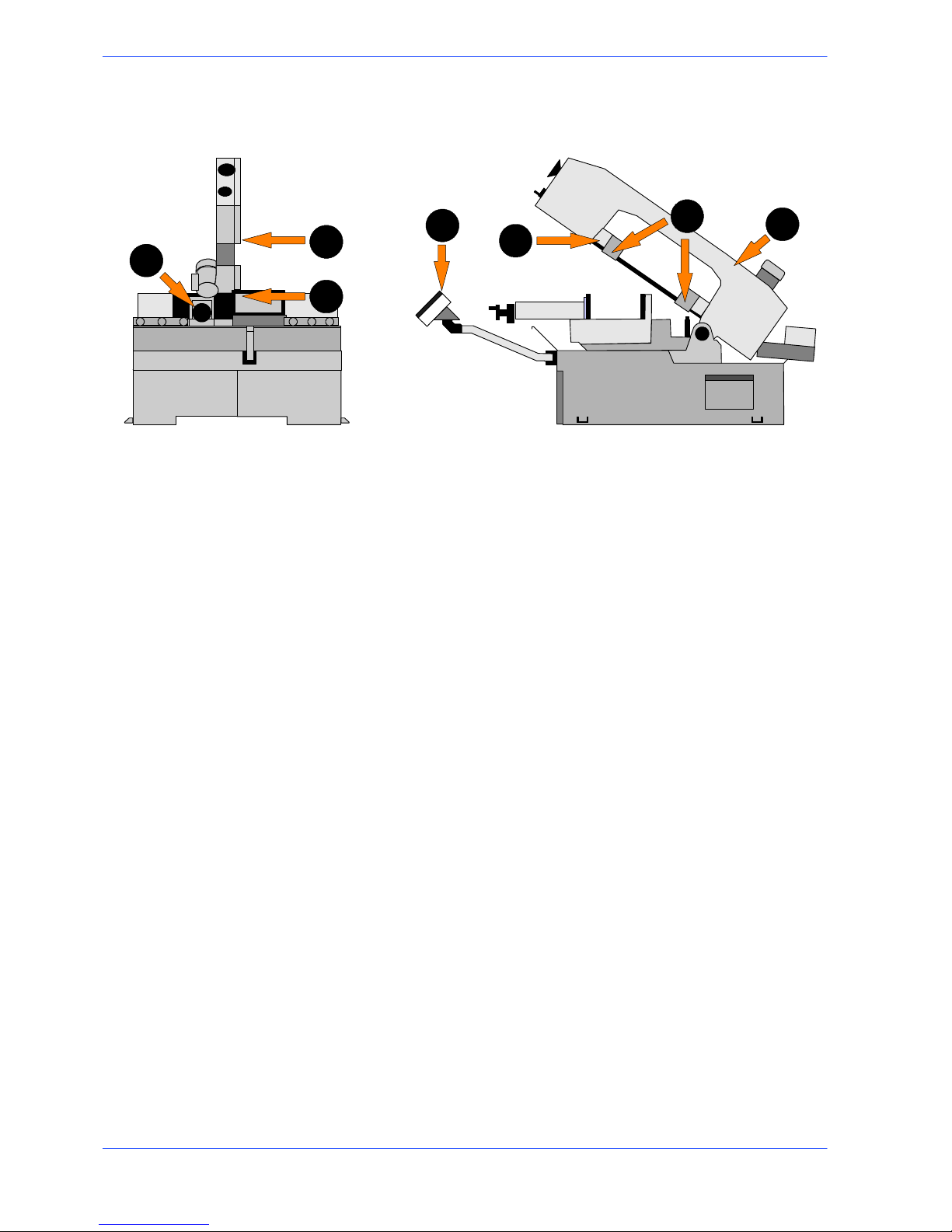
Protection against accidental contact with the blade
1. Metal guard screwed to the rear blade guide head (machine side);
2. metal guard screwed to the front blade guide head (operator side);
3. front head sliding support: when the head is at maximum aperture, the support ensures that the blade is covered, leaving free only the part of the blade
engaged in the actual cutting, in accordance with Presidential Decree no.
547/55, art. 108;
4. hinged protective cover over blade, fitted with removable closing devices;
5. blade guide plates completely covering the blade teeth;
6. The cutting vice is activated by pneumatic devices (in the AV version), with a
maximum run of 8mm. The jaw that performs blocking of the piece must be
neared to the object to be worked at a distance of 2÷3 mm
3--6
18
Use and maintenance manual S --20DS
7. programming and control panel mounted on an articulated, adjustable arm,
so that the operator is always at a safe distance from moving components.
5
2
1
6
4
3
7
Electrical equipment
In accordance with Italian standard CEI 60204---1, April 1998, derived from
European Standard EN 60204---1 publication IEC 204---1, 1997:
H Access to electrical control panel limited by screws and panel ---lock device,
allowing panel to be opened only after the electricity supply has been turned
off;
H 24 Vac Control voltage for actuators, in accordance with chapter 6 or Euro-
pean Standard ”Control and indication circuits”, paragraph 2 ”Control Circuits” sub---section 1 ”Preferential voltage values for control circuits”;
H plant short---circuit protection by means of rapid fuses, earthing of all plant
parts connected with work as well as all foreseeable accidental contact; a thermal---magnetic overload cutout switch shuts down the motor;
H protection from accidental start---up by a minimum voltage relay in case of
power failure.
3--7
19
Safety and accident prevention
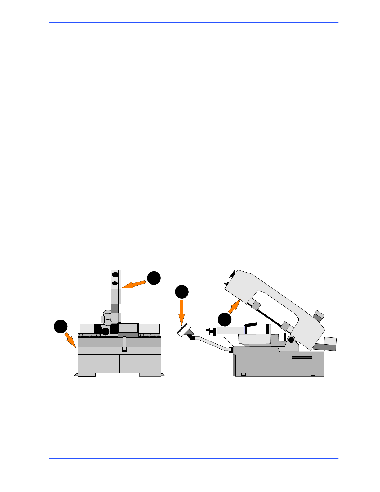
Emergency devices
In accordance with Standard CEI 204---1:
H Chapter 5 Section 6 Sub--section 1 ”Emergency stop device”: «the emergency
stop device immediately stops all the dangerous and other functions of the m achine»;
H chapter 6 Section 2 Sub--section 4 Point 7 ”Protective guards”: «the removal of
protective guards designed to prevent access to dangerous parts or zones causes the
machine to stop immediately; replacing the guards does not restart the functions,
which must be reset».
...Emergency devices applicable to the S ---20DS:
1. Emergency stop: a non--- return mushroom ---head pushbutton, colour red on
yellow background, is located on the control panel of the machine. To release
the pushbutton, the actuator must be rotated 45˚. After the emergency situation has been resolved, the machine must be reset.
2. Automatic thermal---magnetic cutout switch with thermal---magnetic relay:
The machine’s automatic switch, positioned on the left ---hand side of the
base, has two protective systems against the lack of voltage. In fact, if there is
a lack of voltage, it disconnects all electrical devices, blocking the machine
immediately and impedes the automatic restore of the voltage. The other
function is that of re---arming the circuit breaker relay, positioned to protect
from the overloads of current.
3. Pressure transducer for monitoring the blade tension: the machine stops immediately if the blade breaks or the tensioner cylinder pressure drops.
4. Protective guard for blade: a coded key microswitch is operated if the blade
cover is accidentally or intentionally opened during the machine operating
cycle, immediately shutting down all functions.
1
2
3
4

3--8
20
Use and maintenance manual S --20DS
Noise level of the machine
Noise can cause hearing damage and represents one the problems faced by many
countries who adopt their own standards. In accordance with the EEC MA-
CHINES DIRECTIVE 98/37/CE , we are listing the standards that specify noise
levels for machine tools. This chapter also reports the noise levels produced by
the S---20DS during its various operating phases and the methods used for
measuring these levels. The Italian standard governing this aspect is
D.M.n.277/91 drawn from EEC Directives 80/1107, 82/605, 83/477, 86/188, 88/642.
Noise level measurement
Noise levels are measured using an instrument known as an Integrator noise--meter which registers the equivalent continuous acoustic pressure level at the
work station.The damage caused by noise depends on three parameters: level,
frequency and duration. The equivalent level concept Leq combines the three
parameters and supplies just one indication. The Leq is based on the principle of
equal energy, and represents the continuous stationary level containing the same
amount of energy, expressed in dBA, as that actually fluctuating over the same
period of time.This calculation is made automatically by the integrator noise--meter. The measurements are taken every 60 seconds, in order to obtain a
stabilised value. The reading stays on the display for a sufficient time to enable a
reading to be taken by the operator.Measurements are taken by holding the
instrument at approximately 1 metre from the machine at a height of 1.60 metres
above the platform at the operator’s work station.
Two measurements are taken: the first while the machine operates without cutting
anything, the second while cutting in manual mode.
Noise level values
Identification
Machine type Band saw for metal applications
Model
S---20DS
Reference standard ISO 3746
Results
Description
C53 ste el cut --- pipe 356 x 286 mm
Bimetal band 4500 x 27 x 0, 9
Test 1 s t 0
Results
Mean sound level (Leq) 71,00 dB (A)
Environmental correction (K) 3,76 dB(A)
Peak sound power (Lw) 81,93 dB(A)
Descriprion
C 40 steel cut --- HPE 400 x 300 mm
Bimetal band 4500 x 27 x 0, 9
Te st 2nd
Results
Mean sound level (Leq) 68,92 dB(A)
Environmental correction (K) 3,76 dB(A)
Peak sound power (Lw) 81,90 dB(A)
Description
34CND6 material cut ---pipe Ø 150 mm
Bimetal band 4500 x 27 x 0, 9
Test 3rd
Results
Mean sound level (Leq) 69,07 dB(A)
Environmental correction (K) 3,76 dB(A)
Peak sound power (Lw) 79,78 dB(A)

3--9
21
Safety and accident prevention
Electromagnetic compatibility
As from 1 January 1996 all electrical and electronic appliances bearing the CE
marking that are sold on the European market must conform to Directive
89/336/EEC and decree law no. 476/92 concerning electromagnetic compatibility,
i.e. the compatibility of electrical/electronic devices and systems with the
electromagnetic environment in which they are located. The prescriptions regard
two specific aspects in particular:
1. “EMISSIONS: during its operation, the appliance or system must not emit spurious
electromagnetic signals of such magnitude as to contaminate the surrounding
electromagnetic environment beyond clearly prescribed limits”;
2. “IMMUNITY: the appliance or system must be able to operate correctly even when
it is placed in an electromagnetic environment that is contaminated by disturbances
of defined magnitude”.
The following text contains a list of the applied standards and the results of the
electromagnetic compatibility testing of machine model S ---20DS; Test report no.
140201.
Emissions
H EN 50081--2 (1994) Electromagnetic Compatibility -- Generic standard regarding
emissions. Part 2: Industrial Environment.
H EN 55011 (1999) Industrial, scientific, and medical radio frequency appliances
(ISM). C haracteristics of radio frequency disturbance -- Limits and methods of
measurement.
H EN 55014--1 + A2 (1998--1999) Electromagnetic Compatibility -- Prescriptions for
domestic appliances, electric power tools, and similar equipment. Part 1: Standard
Emission in relation to product family.
CONDUCTED EMISSIONS
Gate A Freq. (MH z) Q --- p e a k l i m i t ( d B u V ) Mean value limit (dBuV) Result
A.C. power supply
input
0.15 --- 0.5
0 . 5 --- 5
5 --- 3 0
79 --- 73
(linear reduction with
log of frequency)
73
73
66 --- 60
(linear reduction with log of fre-
quency)
60
60
Complies
CONDUCTED EMISSIONS --- ANALYSIS OF INTERMITTENT DISTURBANCES
Gate Result
A.C. power supply input Not applicable
IRRADIATED EMISSIONS
Gate Freq. (MH z) Q---peak limit (10 m)
(dBuV/m)
Result
Enclosure 30 --- 230
230 --- 1000
40
47
Complies

3--1022Use and maintenance manual S --20DS
Immunity
H EN 50082--2 (1995) Electromagnetic Compatibility -- Generic standard on immuni-
ty. Part 2: Industrial Environment.
H EN 61000--4--2 + A1 (1996--1999) Electromagnetic Compatibility (EMC) -- Part 4:
Test and measurement techniques -- Section 2: Electrostatic discharge immunity
tests -- Basic publication.
H IEC 801--3 (1984) Electromagnetic Compatibility for industrial process measuring
and control equipment. Part 3: Prescriptions relative to irradiated electromagnetic
fields.
H EN 61000--4--4 (1996) Electromagnetic Compatibility (EMC) -- Part 4: Test and
measurement techniques -- S ection 4: Fast transients/bursts immunity tests -- Basic
publication.
H EN 61000--4--6 (1995) Electromagnetic Compatibility (EMC) -- Part 4: Test and
measurement techniques -- Section 6: Immunity to conducted interference, induced
by radio frequency fields.
H ENV 50204 (1996) Electromagnetic field irradiated from digital wireless telepho-
nes.
IMMUNITY TO ELECTROSTATIC DISCHARGES
Gate Test levels Evaluation criterion Result
Enclosure contact 4 kV
steel plate 4 kV
in air 8 kV
B Complies
IMMUNITY TO VOLTAGE (BURSTS)
Gate Test levels Evaluation criterion Result
A.C. power supply in-
put
2kV B Complies
IMMUNITY TO CONDUCTED ELECTROMAGNETIC FIELDS
Gate Test levels Evaluation criterion Result
A.C. power supply in-
put
10V A Complies
IMMUNITY TO IRRADIATED ELECTROMAGNETIC FIELDS
Gate Test levels Evaluation criterion Result
Enclosure 10 V/m A Complies
4--1
Machine installation
Packaging and storage
Hyd---Mech use packing materials that guarantee the integrity and protection of
the machine during its transport to the customer.
The type of packing differs according to the size, weight and destination.
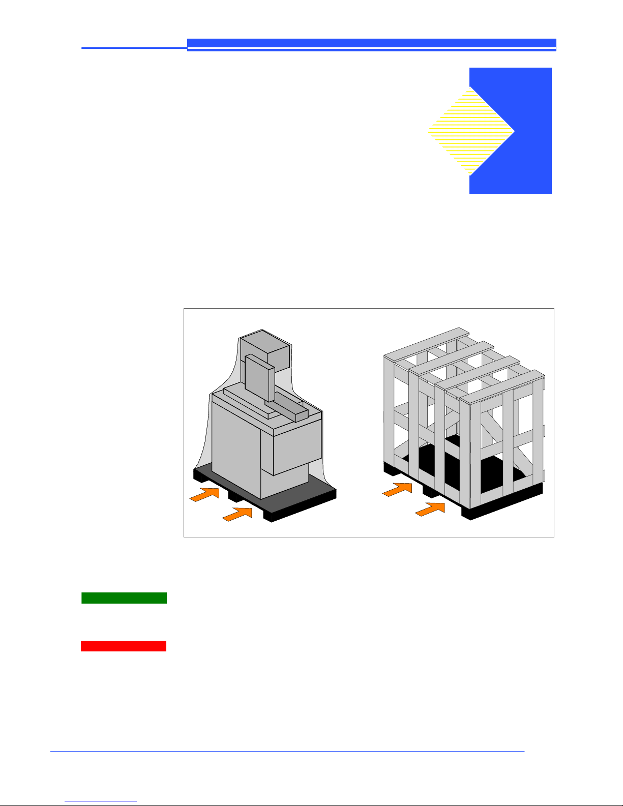
Therefore the customer will receive the machine in one of two following ways:
1. on a pallet with straps and heat---shrink plastic;
2. on a pallet with straps, heat---shrink plastic and a wooden crate.
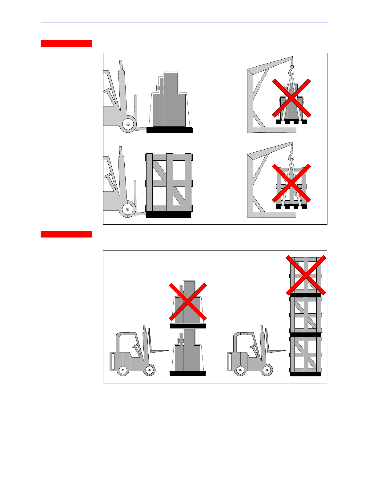
In both cases, for correct balancing the machine must be handled using a
fork--lift truck, inserting the tines at the points indicated by the arrows, using
the reference marks on the crate itself.
Before carrying out lifting operations, make sure that the weight of the machine, as indicated on the crating or other packaging, is within the forklift truck
load limit.
Warning
Attention
4
4--2
24
Use and maintenance manual S --20DS
Do not handle the packed machine using slings.
When storing, machines palletized and shrink--wrapped must not be stacked
two high, and machines pallettized and crated must not be stacked three high.
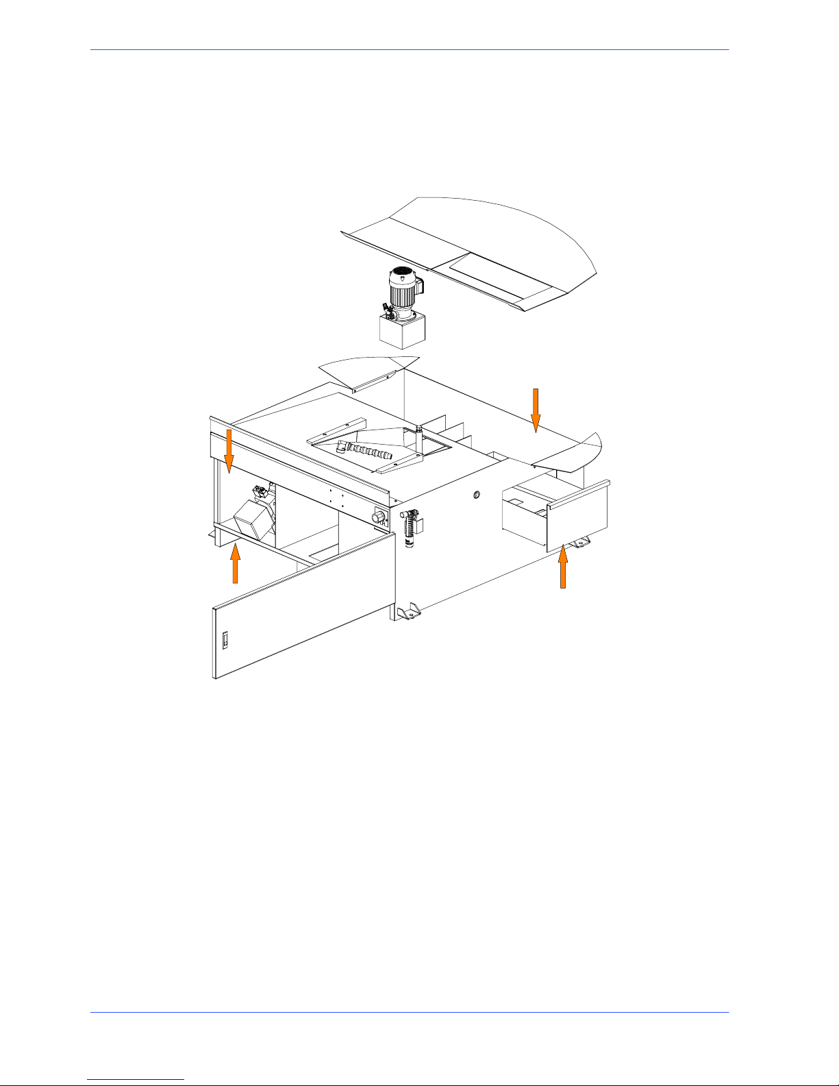
To install the machine, first remove the packing, paying particular attention not to
cut any electric wires or hydraulic hoses; if necessary use pliers, a hammer and a
cutter.
Open crate in the illustrated order:
Attention
Attention
 Loading...