

Hyd-Mech P 225 Use And Maintenance Manual
EN
YEAR OF MANUFACTURE: ______________
P 225
USE AND MAINTENANCE MANUAL


Operation and maintenance manual for P 225 1..................
FOREWORD 1......................................................
TECHNICAL DATA TABLE 1........................................
INTRODUCTION 2.................................................
MACHINE SPECIFICATIONS 2......................................
CHAPTER 1 --- Functional parts of the machine 4.................
1.1 --- Cutting head 4..................................................
1 . 2 --- Vi c e 4.........................................................
1.3 --- Lubricant/coolant system 4.......................................
CHAPTER 2 --- Safety 5.......................................
2.1 --- Intended use of the machine 5....................................
2.2 --- General recommendations 5......................................
2.3 --- Recommendations for the operator 5..............................
2.4 --- Machine safety devices 6.........................................
2.4.1 --- Reference standards 6..........................................
2.4.2 --- Protection against accidental contact with the blade 7...............
2.4.3 --- Electrical equipment 7.........................................
2.5 --- Airborne noise from the machine 7................................
2.5.1 --- Methods of measuring sound level values 7........................
2.5.2 --- Noise level values 7............................................
2.6 --- Electromagnetic compatibility 8...................................
2.6.1 --- Emissions 8...................................................
2.6.2 --- Immunity 8...................................................
CHAPTER 3 --- Installing the machine 9.........................
3.1 --- Unpacking the machine 9........................................
3 . 2 --- C h e c k l i s t 9....................................................
3.3 --- Minimum requirements 9........................................
3.5 --- Connecting electrical power supply 10...............................
CHAPTER 4 --- Machine operation 11............................
4.1 --- Description of controls 11.........................................
4.2 --- Manual operating cycle 12.........................................
CHAPTER 5 --- Drawings, exploded diagrams and spare parts 13.....
5.1 --- Diagrams 13....................................................
5.1.1 --- Electrical diagrams 13...........................................
How to read the wiring diagrams 13......................................
5.2 --- Exploded views 20...............................................
5.2.1 --- Head assembly 20..............................................
5.2.2 --- Vice assembly 22...............................................
5.2.3 --- Handgrip 24...................................................
CHAPTER 6 --- Adjustments 26.................................
6 . 1 --- B la d e 2 6........................................................
6.1.1 --- Performing angled cuts 26........................................
6.2 --- Changing blade 26...............................................
CHAPTER 7 --- Maintenance and choice of expendable materials 27..
7.1 --- Role of the operator responsible for the machine 27...................
7.2 --- Recommendations for maintenance 27..............................
7.3 --- General machine maintenance 27..................................

7.3.1 --- Daily 27.......................................................
7.3.2 --- Weekly 27.....................................................
7.3.3 --- Monthly 27....................................................
7.4 --- Maintenance o f working units 27...................................
7.4.1 --- Transmission box 27............................................
7.5 --- Expendable materials 27..........................................
7.5.1 --- Transmission box oils 27.........................................
7.5.2 --- Oils for the lubricant/coolant fluid 27..............................
CHAPTER 8 --- Choice of blades 28..............................
8.1 --- Choice of blade 28...............................................
8.1.1 --- Tooth pi tch 28.................................................
8.1.2 --- Cutting and feeding speed 28....................................
8.1.3 --- Lubricating/cooling fluid 28......................................
8.1.4 --- Blade structure 29..............................................
8.1.5 --- Types of blade 29...............................................
8.1.6 --- Recommended cutting parameter table 31..........................
8.2 --- Classification of ste els 32..........................................
8.2.1 --- Steel nomenclature table 32......................................
CHAPTER 9 --- Diagnostics tables 33.............................
9.1 --- Diagnostics for blades and cuts 33..................................
9.2 --- Troubleshooting 35...............................................

P 225 1
Operation and maintenance manual for P 225
FOREWORD
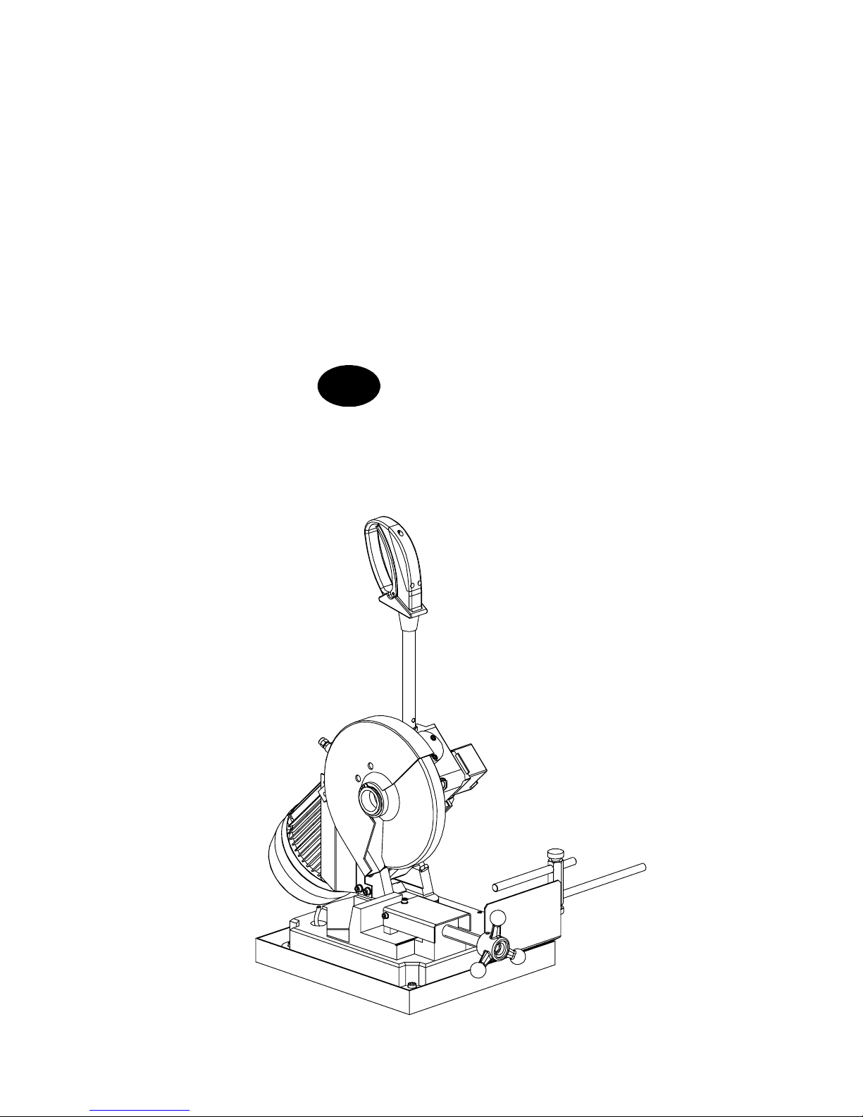
The machine P 225 is a pendulum bench sawing machine designed for cutting metals.
Operation is manual: after turning on the electrical power supply to the machine and clamping the workpiece in the vice,
theoperator starts the bladeby pressing the microswitch located onthecontrol lever; he thenmoves the head downwards
in order to cut the material; after completing the cut, the cutting head returns to position ready for a new cutting cycle.
TECHNICAL DATA TABLE
P 225 U.M. DATA
DISC BLADE
External blade diameter -- profiles / solid pieces mm 225
Diameter of internal hole mm 32
Blade thickness mm 2
CUTTING SPEED
Standard speed rpm 50
VALUES OF POWER AND CONSUMPTION
Head spindle motor 2--4 poles std. 2 speed kW 0.8
Maximum installed electrical power kW 0.8
Oil for lubrication/cooling liquid (concentration 5--6 %) capacity kg 0.7
Transmission box oil capacity Lt. 2.5
Presentation
P 2252
INTRODUCTION
This working tool has been designed to provide a simple and reliable solution to the needs of DIY enthusiasts and fitters who
work with metals and require a practical and versatile machine.
The P 225, is a compact, lightweight pendulum sawing machine that can perform cuts angled by 45° to the left; these features
make the P 225 a versatile and economical machine.
Congratulations on choosing the P 225. This machine will give you many years of trouble--free operation provided you follow
the instructions given in this operation and maintenance manual.
MACHINE SPECIFICATIONS
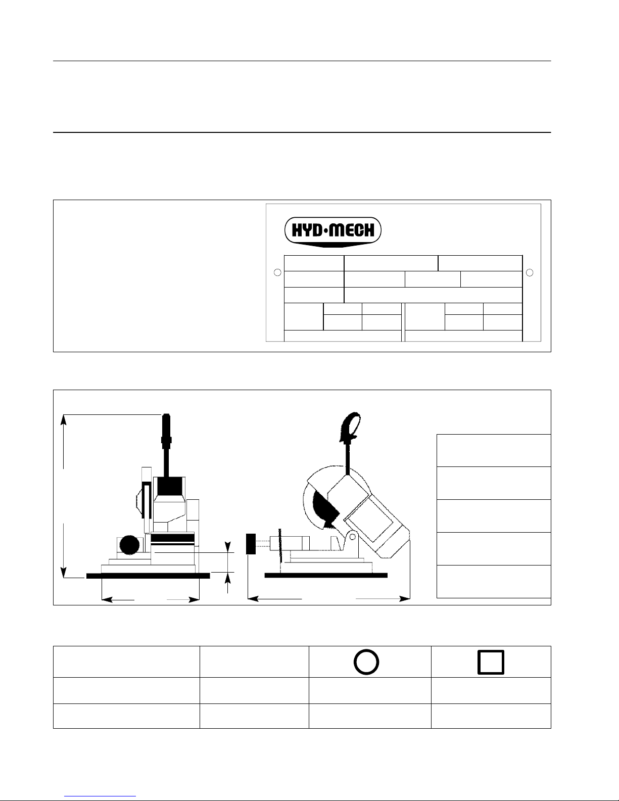
IDENTIFICATION PLATE:
The anodized aluminium identification plate is
riveted to the side of the machine.
IMPORTANT: everytimeyou contact the Service Centre make sure you quote the model,
serial number and year of manufacture given
on the plate.
bar bar
------ --
V
1PH
AVA
3PH
model
air pressure
data code
oil pressure
HYD--MECH
The Rock Solid Solution
DIMENSIONS:
a = 640 mm
b=90mm
c = 370 mm
d = 710 mm
weight = 38 kg
a
d
c
b
CUTTING CAPACITY FOR PROFILES :
0 degrees
65
60
Cross--section
55 50
45 degrees left
Blade
diameter
225
225

Presentation
P 225 3
CUTTING CAPACITY FOR SOLID PIECES :
0 degrees
45
45
Cross--section
40 40
45 degrees left
Blade
diameter
225
225
Max. opening of cutting vice:70mm
DISC BLADE:
Dimensions: HM 225x32x2mm for solid pieces and profiles
Cutting speed: standard 50 r.p.m.
SPINDLE MOTOR:
Spindle motor: single phase 4 poles; 50 Hz; IP 54.
Characteristics:
Voltage Volt Absorption Amp. Power kW r.p.m.
4 poles
230 5.8 0.8 1.355
Stator winding in enamelled copper class H 200° C;
Insulation class F (limit temperature TL=155° C);
Example of class F insulation : in air--cooled machines at a room temperature of 40° C (in accordance with CEI 2--3 and
IEC 85) the admissible overtemperature is 100° C (where 100° C represents the admissible ∆T).
IP 54 protection rating (total protection against contact with live parts and against water sprayed from any direction).
Complies with CEI standards, IEC publication 34 of 1 July 1985.
P 2254
CHAPTER 1 -- Functional parts of the machine
In order to gain a good understanding ofthemachine,whichwill
be described in detail in the chapter ”MACHINE OPERATION”,
we will look at its main units and their respective positions.
1.1 -- Cutting head
The cutting head is the unit that performs the cut and consists of
acasti ron section on whichthefollowingparts are mounted: the
blade,the bladesupportunits,thedrivetransmissionunitandthe
spindlemotor. Thecuttinghead isfixedto theturntablebymeans
of a hinge and travels downwards to perform the cut. The
upwards and downward movement of the head is controlled
manually by the operator.
1.2 -- Vice
Theviceistheunitthatholdstheworkpiecesteadyduringcutting;
itconsistsof avicesupporton whichtheslide withthemobilejaw
and the fixed jaw is mounted. The vice support is fixed to the
upper section of the base.
1.3 -- Lubricant/coolant s ystem
The lubricant/coolant system consists of a membrane pump
driven by a cam mechanical system located on the shaft onto
which the blade is flanged.
P 225 5
CHAPTER 2 -- Safety
TheP 225hasbeendesignedandconstructedtocomplywithEuropean standards.
It is extremely importantthat you follow the instructions given in
this chapter, as they are essential for correct use of the
machine.
2.1 -- Intended use of the machine
Thependulumdisc sawingmachineP 225is intendedtobeused
exclusively for cutting metal profiles. The machine’s specific
characteristicsmake itunsuitablefor othertypes ofmaterial
or process.
Personneltraining istheresponsibilityofthe employer,whomust
inform operators about risks of accident, safety devices, risks
related to noise emission and general safety precautions laid
down by international directives and legislation of the country in
which the machine is used. The operator must be fully aware
of the position a nd operation of all the machine’s controls.
The instructions, warnings and general safety precautions
describedin thismanual mustbe followedcompletely bythe
personnel using the machine.
Inaccordance withthe MACHINERYDIRECTIVE 98/37/CEEEC
and subsequent supplements and amendments
91/368--93/44--93/68, the following definitions are used:
` ”Dangerzone”: anyzonewithin and/oraroundmachineryin
which an exposed person is subject to a risk to his health or
safety.
` ”Exposed person”: any person wholly or partially in a
danger zone.
` ”Operator”: the person or persons given the task of instal-
ling, operating, adjusting, maintaining, cleaning, repairing or
transporting machinery.
WARNING: The manufacturer is released from all civil and
criminal liability if one or more parts orunitsofthemachine
are tampered with and/or replaced without due authorisation, or if any accessories, tools and expendable materials
are used other than those recommended by the
manufacturer,orifthemachine is inserted in a complex system or it is used in any way that is different from the intended use.
2.2 -- General recommendations
LIGHTING
A lack of adequate lighting for the intended type of operation
couldleadto risks forthesafetyof personnel. Forthisreasonthe
userofthemachinemust ensurethatsuitablelightingis provided
for the working environment in order to eliminate any areas of
shadow or irritating glare. (Reference standard ISO 8995--89
”Lighting in working environments”).
CONNECTIONS
On the basis of the machine’s power absorption levels given in
the ”Machine specifications” tables on page 2, check that the
electric and pneumatic power supply lines are able to withstand
themachine’smaximum absorptionlevelsandmakeany necessary changes.
EARTHING SYSTEM
Theearthingsystemmustmeetprecisespecifications asprescri bed by the IEC STANDARD 204.
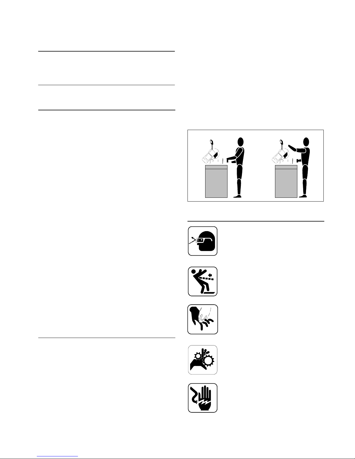
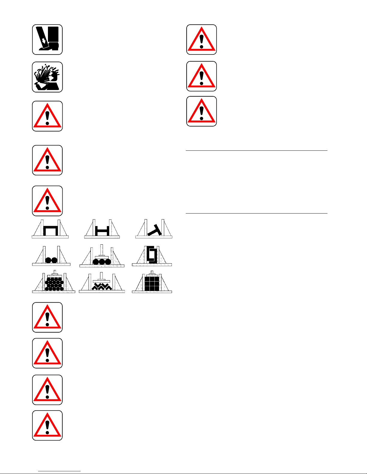
OPERATOR POSITION
Theoperatorusingthe machine mustbeinthe position shown in
the diagram below.
2.3 -- Recommendations for the operator
Always wear adequate s afety glasses.
Do not use the machine without the guards in
position.
Do not place your hands or arms in the cutting
zone while the machine is working or the tool is
still turning.
Do not wear loose-- fitting clothing, longsleeves,
gloves of the wrong size, bracelets, c hains or
anything else that might get caught in the
machine during operation; tie back long hair.
Always disconnect the machine from the
electrical power supply before carrying out any
maintenance work on the machine or changing
theblade.Thisalsoapplies to operations that lie
outside the normal use of the machine.
Safety
P 2256
Beforestarting tocut,makesurethatthematerial
is adequately supported on both sides of the
machine.
Work may be carried out on the hydraulic and
pneumaticsystemsonlyafterthepressureinside
them has been released.
Theoperatormustavoid operations that areunsafe or not appropriate for the job being
performed (e.g. removing swarf from the
machine while cutting).
Clearthecuttingareaoftools,implementsand all
otherobjects;keeptheworking area ascleanas
possible.
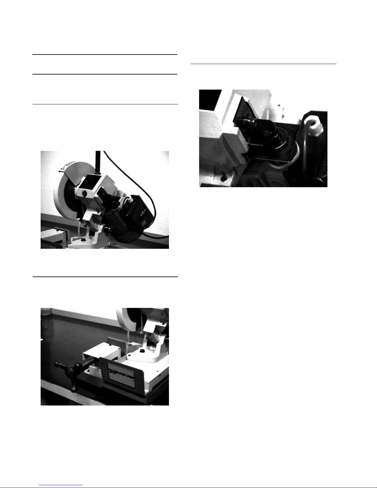
Before starting the c utting operation, make sure
that the workpiece is held securely by the vice
and that the machine is correctly set up. The
following are examples of how different section
bars can be locked on our sawing machines.
Do not use the machine for cutting workpieces
that exceed the capacity stated on the technical
sheet.
Do not move the machine while it is cutting.
Donot usebladeswith differentdimensionsfrom
those declared in the machine specifications.
Whencuttingextremelyshort workpieces, make
sure that they are not dragged behind the rest
shoulder as this gives rise to a risk of the blade
seizing.
When operating the saw, wear gloves only for
handling material and for adjusting or changing
the blade. Carryoutonlyoneoperationatatime
and do not fill your hands with more than one
object at the same time. Keep your hands as
clean as possible.
Warning: ifthebladeseizeswhile cutting,immediately press the machine’s emergency stop
button. If the blade does not free, open the vice
slowly,removethe workpieceandcheckthat the
blade and the teeth are not broken. If they are,
replace the blade.
Before carrying out any repair work on the
machine,contactthe Technicalservice centreor
if necessary its representatives in the country in
which the machine is used.
2.4 -- Machine safety devices
This operation and maintenance manual is not intended to be
solely a guide to using the machine for the purposes of
production, but provides instructions to ensure that it is used
correctlywitha view tothesafetyof workers.Belowisa list ofthe
standards prescribedbytheEECcouncilcontainedindirectives
regarding the safety of machinery, safety at the workplace,
personal protection and environment protection. These
standards have been applied to the P 225.
2.4.1 -- Reference standards
SAFETY OF MACHINERY
` EEC directive no. 98/37/CE of 14.06.1989 known as the
”Machinery directive”.
` EEC directives nos. 91/368;93/44;93/68 amending EEC di-
rective no. 98/37/CE regarding the safety of machinery.
` EEC directive no. 73/23 known as the ”Low tension
directive”.
SAFETY AT THE WORKPLACE
` EECdirectivesnos.80/1107;83/477;86/188;88/188;88/642
relating tothesafeguardingofworkersagainstrisksderiving
from exposure to chemical, physical and biological agents
during work.
` EEC directive no. 89/391 and Special EEC directives no.
89/654 and no. 89/655 relating to the improvement of health
and safety of workers at work.
` EEC directive no. 90/394 relating to the safeguarding of
workersagainstrisks deriving fromexposure to carcinogenic
agents during work.
` EEC directives no. 77/576 and no. 79/640 regarding safety
signs at the workplace.
INDIVIDUAL PROTECTION
` EECdirectivesno.89/656 and no. 89/686 regarding theuse
of individual protective devices.
ENVIRONMENT PROTECTION
` EEC directive no. 75/442 regarding waste disposal.
` EECdirective no. 75/439 regarding the disposal of used oil.
Safety
P 225 7
2.4.2 -- Protection against accidental contact with
the blade
2
1
¡ Metal blade guard fixed to the cutting head;
© mobile blade guard attached to the fixed guard and the
machinebodytoensurethatthebladeiscoveredand thatonly
the part of the blade engaged in cutting is left free, as
prescribed by the DPR 547/55 art.108.
2.4.3 -- Electrical equipment
Inaccordance withtheItalianstandardCEI60204--1,September
1993, deriving from the European standard EN 60204--1 IEC
publication 204--1, 1992:
- Accessibility to the electrical panel restricted by screws;
- earthing of all parts subject to risk of contact accidentally or
during work;
- thepower supply sectioningdevicerealisedwith a socket/plug
combination in accordance with 5.3.2 sub--section c.
2.5 -- Airborne noise from the machine
Noise causes damage to hearing and is a problem that many
countries tackle by laying down specific regulations. In
conformity with the regulations established by the Machinery
Directive98/37/CE/EEC,weherebyinformyouofthestandards
prescribing the sound level threshold for machine tools. This
chapterprovidesthevaluesofairbornenoiselevelsgeneratedby
the P 225 in the various stages of its operation and the method
used for measuring the sound level values. This situation is
regulated in ITALYbytheD.M.no.277/91whichhas adopted the
Community Directives 80/1107/EEC, 82/605/EEC,
83/477/EEC, 86/188/EEC, 88/642/EEC.
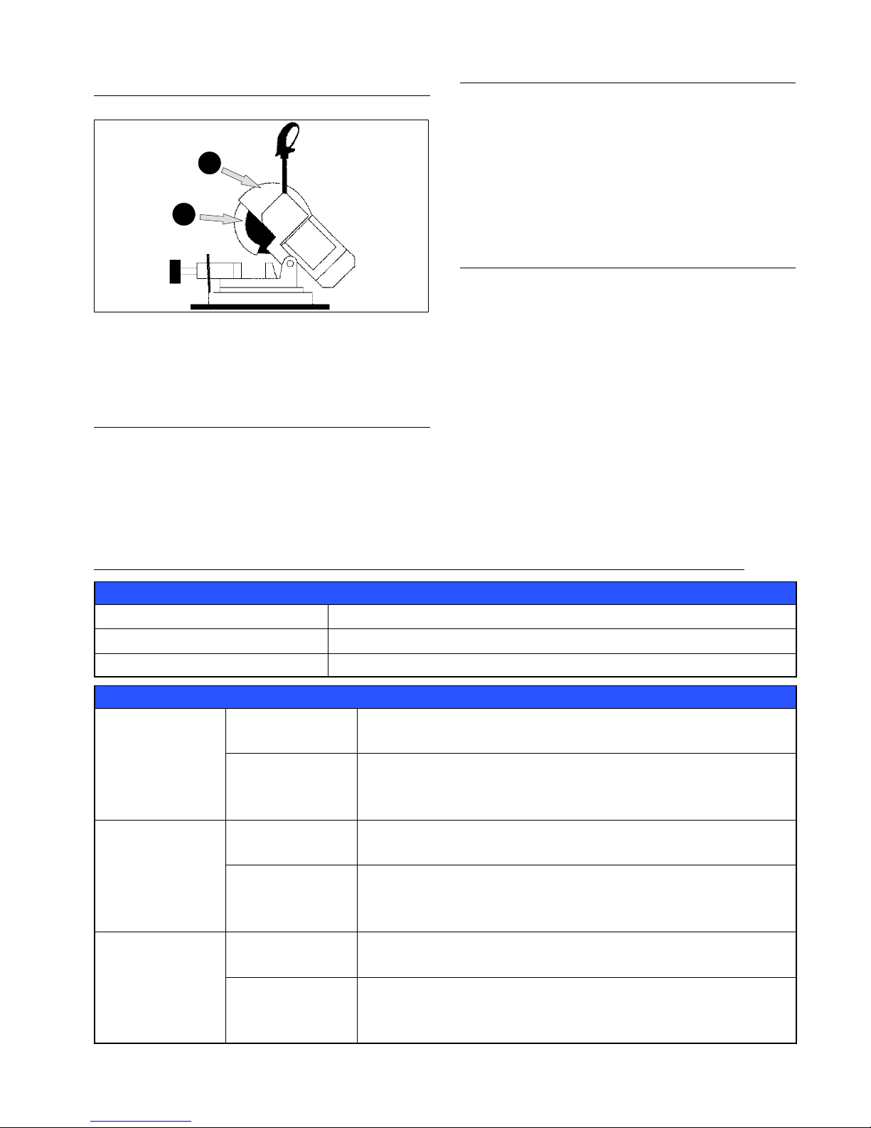
2.5.1 -- Methods of measuring sound level values
The sound level measurements are carried out using an
instrument called an Integrating sound level meter which
serves to measure the weighted equivalent continuous sound
pressure level at the workplace.
The damage caused by noise depends on three factors: level,
frequency distribution and duration. The concept of equivalent
level L
eq
combines the three factors so as to provide just one
simpleparameter. TheL
eq
isbasedon theequal energyprinciple
and represents the continuous stationary level with the same
energycontent,expressedindBA, as the real fluctuating levelin
the same period of time.
This calculation is performed automatically by the integrating
sound level meter. Each measurement lasts for 60 seconds to
allow the value to stabilise; the value obtained remains on the
display to give the operator time to read it.
Measurements are made with the equipment held at a distance
ofabout1metrefrom the machineandataheight of 1.60mfrom
the operator’s workplace platform. Two measurements are
made: the first while the machine is performing a manual cut
without a workpiece; the second while the material is being cut
manually.
2.5.2 -- Noise level values
Identification
Machine type
Band saw for metal applications
Model
P 225
Reference standard
ISO 3746
Results
Description
50x15 mm pipe in FE37 steel
Disc blade HSS--DMO5 Ø 225x32x2
Tes t 1
Results
MEAN SOUND LEVEL (Leq) 101.25 dB (A)
Environmental correction (K) 2.78 dB(A)
Peak sound power (Lw) 111.82 dB(A)
Description
35 mm Ø solid tube in FE37 steel.
Disc blade HSS--DMO5 Ø 225x32x2
Tes t 2
Results
MEAN SOUND LEVEL (Leq) 93.16 dB(A)
Environmental correction (K) 2.78 dB(A)
Peak sound power (Lw) 102.34 dB(A)
Description
20 mm Ø solid tube in FE37 steel.
Disc blade HSS--DMO5 Ø 225x32x2
Tes t 3
Results
MEAN SOUND LEVEL (Leq) 89.67 dB(A)
Environmental correction (K) 2.78 dB(A)
Peak sound power (Lw) 98.40 dB(A)

Safety
P 2258
2.6 -- Electromagnetic compatibility
As from 1 January 1996 all electrical and electronic appliances
bearing the CE marking that are sold on the European market
must conform to Directive 89/336/EEC and decree law no.
476/92 concerning electromagnetic compatibility, i.e. the
compatibilityofelectrical/electronicdevicesandsystemswiththe
electromagnetic environment in which they are located. The
prescriptions regard two specific aspects in particular:
1 “EMISSIONS: during its operation, the appliance or system
must not emit spurious electromagnetic signals of such
magnitude as to contaminate the surrounding electromagnetic
environment beyond clearly prescribed limits”;
2 “IMMUNITY:the appliance or system must be able to operate
correctly even when it is placed in an electromagnetic
environment that is contaminated by disturbances of defined
magnitude”.
Thefollowingtext contains alistofthe applied standardsandthe
results of the electromagnetic compatibility testing of machine
model P 225; Test report no. 051200.
2.6.1 -- Emissions
` EN 55014--1 (1998) + A2 (1999) Electromagnetic
Compatibility -- Requirementsforhouseholdappliances,electric
tools and similar apparatus part 1: Emission -- Product family
standard.
` EN 61000 -- 3 -- 2 (1995) + A1/A2 (1998) Electromagnetic
compatibility (EMC) -- Part 3: Limits -- Section 2: Limits for
harmoniccurrentemissions(equipmentinputcurrent<16 Aper
phase).
` EN61000--3 --3(1995) Electromagneticcompatibility (EMC)
-- Part3:Limits -- Section 3: Limitationofvoltage fluctuations and
flicker in low--voltage supply systems for equipment with rated
current < 16 A.
CONDUCTED EMISSIONS
Port Freq. (MHz) Q --- p e a k l i m i t ( d B u V ) Limit average (dBuV) Result
A.C. mains 0.15 --- 0.5
0 . 5 --- 5
5 --- 3 0
66 --- 56
(decreasing linearly with
the logarithm of the fre-
quency)
56
60
56 --- 46
(decreasing linearly with the logar-
ithm of the frequency)
46
50
Pass
CONDUCTED EMISSIONS --- ANALYSIS OF DISCONTINUOUS DISTURBANCE
Port Result
A.C. mains Not applicable
HARMONIC CURRENTS EMISSIONS
Port Limit (class) Result
A.C. mains A Pass
FLICKER AND VOLTAGE VARIATIONS
Port Flicker limit Result Voltage variation limit Result
A.C. mains pst = 1
plt: not applicable
Pass dc = 3%
dmax=4%
d(t) = 200 ms
Pass
2.6.2 -- Immunity
` EN 55014 -- 2 (1998) Electromagnetic compatibility -Requirements for Household appliances, electric tools and
similar apparatus Part 2: Immunity -- Product family standard.
IMMUNITY TESTS
EUT classification Result
Category I
(Apparatus containing no electronic control circuitry)
Pass
(Category 1 apparatus are deemed to fulfil the immunity
requirements without testing)
P 225 9
CHAPTER 3 -- Installing the machine
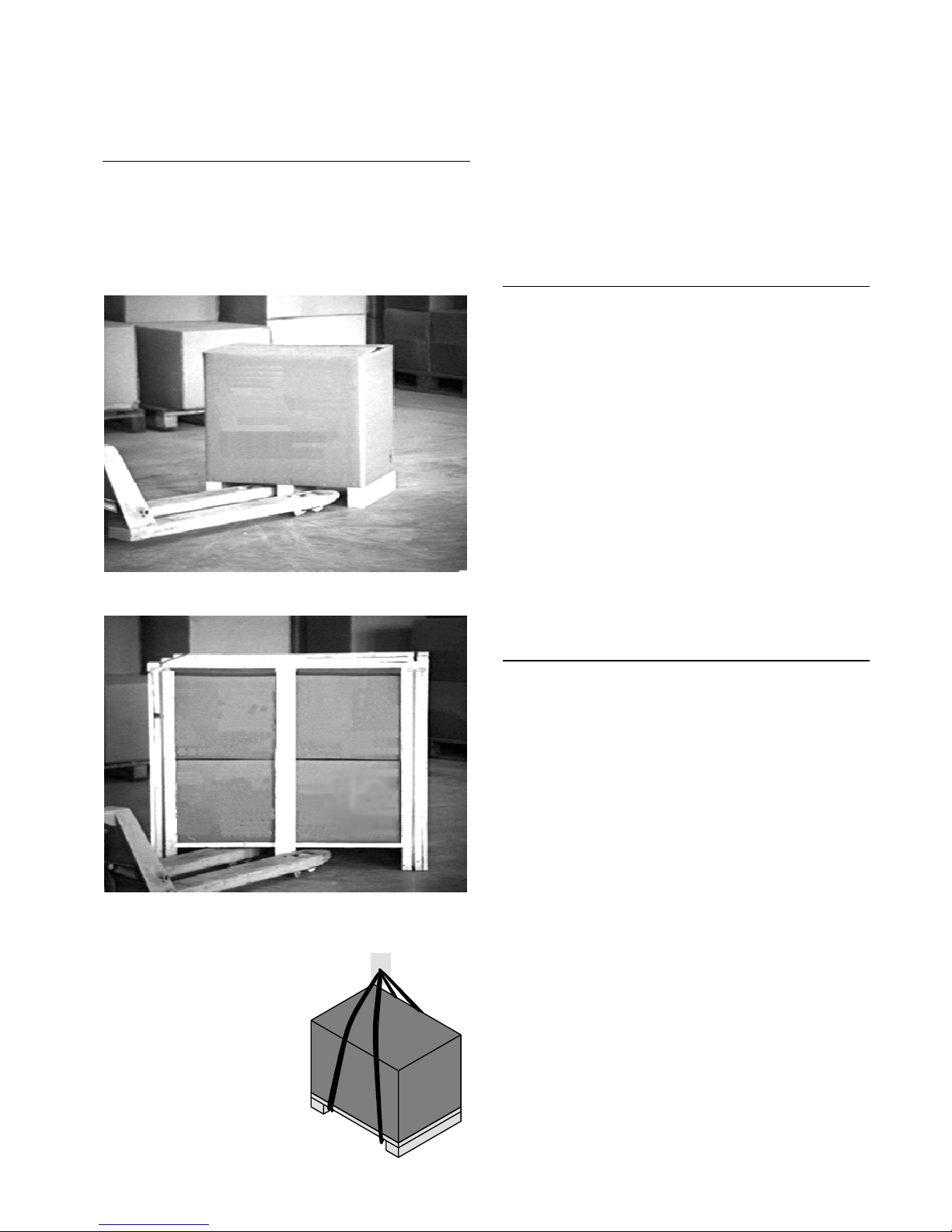
3.1 -- Unpacking the machine
Hyd--Mech uses packagingthat is appropriate for protecting the
machinefromdamageduring transport right upuntilthetimeitis
delivered to the customer.
The type of packaging used for the machine depends on the
dimensions,weightand destination, sothecustomer will receive
the machine in one of the two following ways:
-- package including pallet, straps and cardboard box with
lid.
-- package with pallet, cardboard boxes (for more than one
machine) and wooden crate.
In eithercase,liftthemachineusingaforklifttruck,inserting the
forks at the points marked by the arrows and following the
instructions given on the box.
WARNING! Do not handle the
packaged machine by harnessing with a sling.
Beforeinstalling themachine,removethe packaging,takingcare
not to cut electric cables or hydraulic hoses and using pliers, a
hammer and a cutter as required. To place the machine in its
working position, follow the instructions given in paragraph 3.4.
The working position must be chosen taking into consideration
the machine dimensions and the space required to allow the
operator to perform all necessary manoeuvres to ensure his
safety.
3.2 -- Check list
Before beginning to install the machine, check the standard and
optional accessories provided with the machine. The standard
version of the P 225 1 SPEED sawing machine is supplied complete with:
` pedestal with tank for coolant;
` membrane pump for lubrication and cooling of blade;
` IP 55 head control lever;
` mobile guard to cover part of blade not engaged in cutting;
` rotatinghead withscrewlocking facility toperformangled cuts;
` possibility of performing cuts from 0_ to 45° to the left;
` 1 speed single--phase electric motor;
` bag of accessories.
The bag of accessories is enclosed in the machine before
packaging and contains the following accessories:
` 4, 5, 6, 10 mm Allen keys;
` rod for measured cuts;
` this operation and maintenance manual;
OPTIONAL
ACCESSORIES AVAILABLE ON REQUEST:
` HSS DMo5/M2 D.225x32x2 circular blade for cutting solid
bars and profiles;
` 5 l can of emulsible oil.
3.3 -- Minimum requirements
The following are the minimum environmental requirements
needed to ensure correct operation of the machine:
-- mainsvoltage/frequency:seevaluesgivenonthedataplate;
-- room temperature: from -- 10 to + 50 °C;
-- relative humidity: no higher than 90%;
-- room lighting: no lower than 500 Lux.
WARNING !
Although the machine is protected against voltage
variations, good operation can only be ensured by stable
voltage, which should not vary by more than 10%.
NO
 Loading...