

Hyd-Mech H4040, H4060, H4080 User Manual
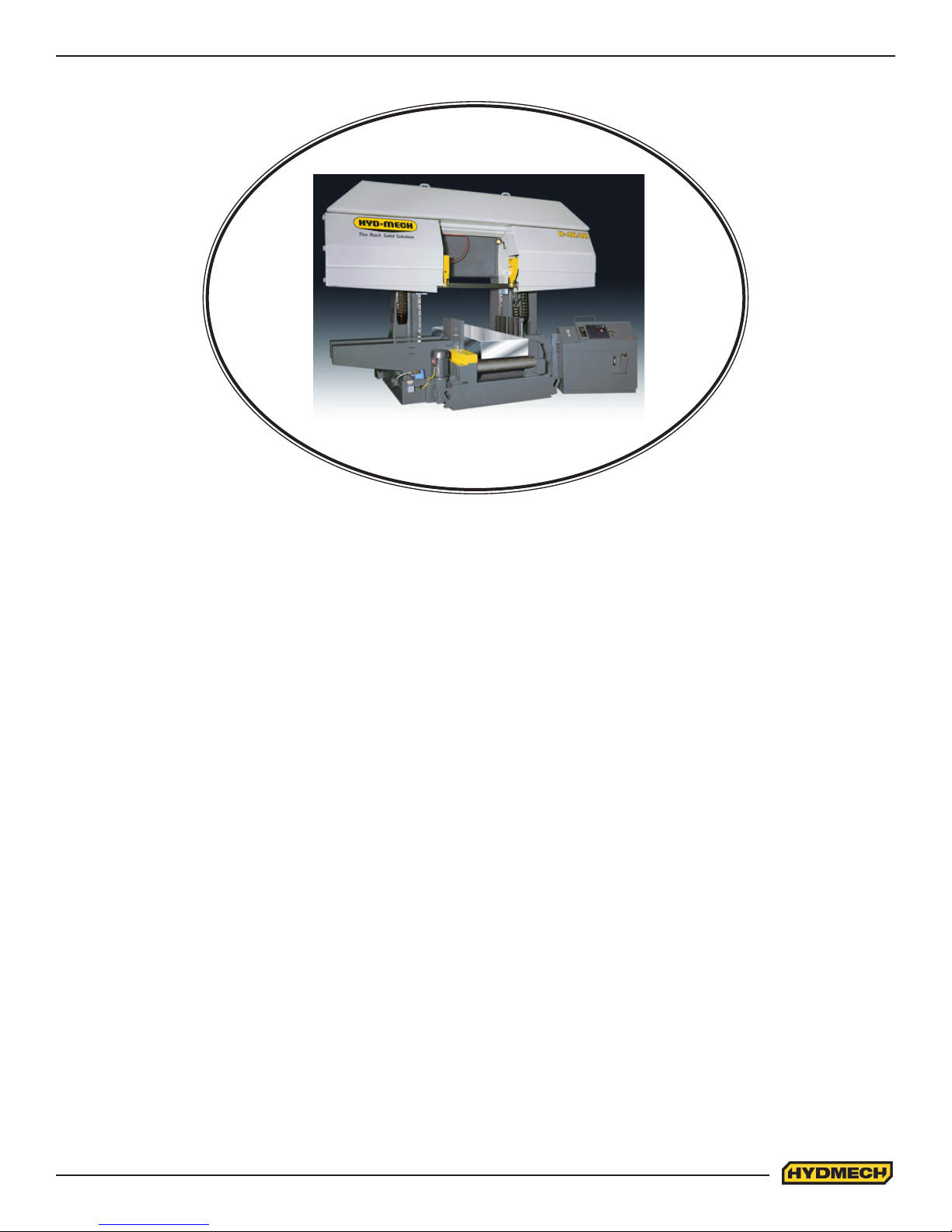
H4040, H4060, H4080
393139
THANK YOU,
On behalf of everyone at HYD·MECH Group Limited, we would like to thank and congratulate you on your decision to
purchase a HYD·MECH bandsaw.
Your new machine is now ready to play a key role in increasing the eciency of your operation, helping you to reduce cost
while boosting quality and productivity.
To ensure you are maximizing the power and versatility of your new HYD·MECH bandsaw, please take the time to
familiarize yourself and your employees with the correct operation and maintenance procedures as outlined in this
manual. Please keep this instruction manual for future reference in a known location and easily accessible to all users of
the device.
HYD·MECH oers a great variety of options, components, and features for its various models. Therefore, some of the
equipment described in this manual (various illustrations and drawings) may not be applicable to your particular machine.
The information and specications provided in this manual were accurate at the time of printing. HYD·MECH reserves the
right to discontinue or change specications or design at any time without notice and without incurring any obligation.
Thank you.
Hyd·Mech Group Limited
P.O. Box 1659, 1079 Parkinson Road
Woodstock, Ontario, N4S 0A9
Phone : (519) 539-6341
Service : 1-877-237-0914
Sales : 1-877-276-SAWS (7297)
Fax : (519) 539-5126
e-mail : info@hydmech.com
PRINTED APRIL 2017
1

TABLE OF CONTENTS
SECTION 0 - SAFETY INSTRUCTIONS
SUMMARY .......................................................................................................................................0.1
BASIC RULES ..................................................................................................................................0.3
RESPONSIBILITIES OF THE OWNER ............................................................................................0.3
RESPONSIBILITIES OF THE OPERATOR AND MAINTENANCE PERSONNEL ...........................0.4
SAFETY HAZARD LABELS .............................................................................................................0.6
SECTION 1 - INSTALLATION
SAFETY PRECAUTIONS .................................................................................................................1.1
LIFTING THE H-40 ...........................................................................................................................1.2
MACHINE LAYOUT ..........................................................................................................................1.3
H-40 INSTALLATION PROCEDURE ................................................................................................1.4
FOUNDATION, LEVELING AND ANCHORING ...............................................................................1.4
HYDRAULIC OIL AND CUTTING FLUID .........................................................................................1.6
WIRING CONNECTIONS .................................................................................................................1.6
SECTION 2 - OPERATING INSTRUCTIONS
BLADE BASICS................................................................................................................................2.1
VARIABLE SPEED CONTROL.........................................................................................................2.1
THE CONTROL PANEL ...................................................................................................................2.1
MANUAL OPERATION .....................................................................................................................2.1
HYDRAULIC FEED CONTROL ........................................................................................................2.6
CUTTING PARAMETERS CHART ...................................................................................................2.7
HEAD DOWN LIMIT SETTING .......................................................................................................2.13
GUIDE ARM POSITIONING ............................................................................................................2.14
COOLANT CONTROLS ..................................................................................................................2.15
SECTION 3 – MAINTENANCE
SAFETY DURING MAINTENANCE AND TROUBLESHOOTING ....................................................3.1
LOCK OUT PROCEDURE ...............................................................................................................3.1
BLADE CHANGE MODE PROCEDURE ..........................................................................................3.2
BLADE BRUSH ADJUSTMENT .......................................................................................................3.4
LUBRICATION ..................................................................................................................................3.5
HYDRAULIC MAINTENANCE ..........................................................................................................3.6
CLEANLINESS .................................................................................................................................3.6
TROUBLE SHOOTING GUIDE ........................................................................................................3.7
ELECTRICAL SCHEMATICS: SEE PDF ON ATTACHED CD .........................................................4.1
SECTION 4 - ELECTRICAL
i

SECTION 5 - HYDRAULIC SYSTEM
HYDRAULIC SCHEMATICS & PLUMBING DIAGRAMS: SEE PDF ON ATTACHED CD ...............5.2
LIST OF H-40 HYDRAULIC COMPONENTS ...................................................................................5.2
SECTION 6 - MECHANICAL ASSEMBLIES
MECHANICAL ASSEMBLY DRAWINGS & PARTS LIST: SEE PDF ON ATTACHED CD ................6.1
SECTION 7 - OPTIONS
OPTIONAL ASSEMBLY DRAWINGS: SEE PDF ON ATTACHED CD .............................................7.1
BLADE DEVIATION MONITORING SYSTEM (K10) ........................................................................7.1
SECTION 8 - SPECIFICATIONS
H4040 SPECIFICATIONS ................................................................................................................8.1
H4060 SPECIFICATIONS ................................................................................................................8.2
H4080 SPECIFICATIONS ................................................................................................................8.3
LAYOUT DRAWING .........................................................................................................................8.4
SECTION 9 - WARRANTY
WARRANTY .....................................................................................................................................9.1
ii

SECTION 0 - SAFETY INSTRUCTIONS
SUMMARY
All persons operating this machine must have read and understood all of the following sections of this Manual:
Section 0 SAFETY
Section 2 OPERATING INSTRUCTIONS
However, as a memory aid, the following is a summary of the Safety Section.
Put Safety First
Mandatory Information – What operators and maintenance people must have read and understood.
Signatures – Everyone involved with this machine must sign to conrm they have read and understood mandatory
information.
Basic Rules – only use this machine when
• It is in good working order.
• All safety equipment is in place and functional.
• Operations are in compliance with this manual.
• Materials are within designed specications and are non-hazardous.
Owner is responsible to
• Keep Manual accessible at the machine.
• Ensure only reliable, fully trained personnel work with the machine.
• Clearly dene responsibilities of all personnel working with the machine.
• Keep the machine in good working order.
Operator and Maintenance Personnel are responsible to:
• Keep all safety equipment in order, check its function at the beginning of each shift, and report any shortcomings.
• Shut down machine and report any faults or malfunctions that could impair safety.
• Understand and obey safety hazard labels.
• Not to wear un-restrained long hair, loose clothing or jewellery.
• Wear all required personal protective equipment.
• Not to wear gloves within 24 inches of moving blade.
• Maintain a clean working area and machine.
• Always use Lock-out when performing maintenance or repairs.
0.1

FOREWORD
Put Safety First!
This Safety Section contains important information to help you work safely with your machine and describes the dangers
inherent to bandsaws. Some of these dangers are obvious, while others are less evident.
It really is important to PUT SAFETY FIRST. Make it a habit to consider the hazards associated with any action BEFORE
you do it. If you feel any uncertainty, stop and nd a safer approach to the action. If you’re still uncertain, ask for advice
from your supervisor.
The SAFETY FIRST approach is particularly necessary when you do something new, or dierent, and most people
instinctively recognize this, although impatience may still cause them to take unnecessary risks.
Danger also lurks in the routine task that we have done over and over. Here, familiarity, boredom, or tiredness may lull us
into unthinking, automatic repetition. Be alert for this, and when you feel it happening, stop and assess your
situation. Review the safety hazards associated with what you are doing. That should get your brain working again.
Certainly production is important, but if you think you’re too busy to put safety rst, think how much production you’ll lose if
you get hurt.
You owe it to yourself, your family, and your co-workers to PUT SAFETY FIRST.
Mandatory Information
All persons operating this machine must have read and understood all of the following sections of this Manual:
Section 0 SAFETY
Section 2 OPERATING INSTRUCTIONS
Personnel involved in installation and maintenance of the machine must have read and understood all sections of the
manual
Persons who have diculty reading, or for whom English is not their rst language, must receive particularly thorough
instruction.
Signatures
Everyone involved in operation of this machine must sign below to conrm that:
I have read and understood all parts of Section 0 – Safety, and Section 2 – Operating Instructions.
Name Date Signature
Everyone involved in the installation, inspection, maintenance, and repair of this machine must sign below to conrm that:
I have read and understood all parts of this Operation and Maintenance Manual.
Name Date Signature
0.2

BASIC RULES
Intended Use
Exclusion of Misuse
Liability
Our machines are designed and built in line with the state of the art, and specically in accordance with
American National Standards Institute Standard B11.10 Safety Requirements for Metal Sawing Machines.
However, all machines may endanger the safety of their users and/or third parties, and be damaged,
or damage other property, if they are operated incorrectly, used beyond their specied capacity, or for
purposes other than those specied in this Manual.
Misuse includes, for example:
Sawing hazardous materials such as magnesium or lead.
Sawing work pieces which exceed the maximum workload appearing in the Specications.
Operating the machine without all original safety equipment and guards.
The machine may only be operated:
When it is in good working order, and
When the operator has read and understood the Safety and Operating Instructions Sections of the
Manual, and
When all operations and procedures are in compliance with this Manual.
Hyd-Mech Group cannot accept any liability for personal injury or property damage due to operator errors
or non-compliance with the Safety and Operating Instructions contained in this Manual.
RESPONSIBILITIES OF THE OWNER
Organization of work
This Operation and Maintenance Manual must always be kept near the machine so that it is accessible to
all concerned.
The general, statutory and other legal regulations on accident prevention and environmental protection
must also be observed, in addition to the Manual material. The operators and maintenance personnel
must be instructed accordingly. This obligation also includes the handling of dangerous substances and
the provision and use of personal protective equipment.
Choice and qualication of personnel
Ensure that work on the machine is only carried out by reliable persons who have been appropriately
trained for such work.
Training
Everyone working on or with the machine must be properly trained with regard to the correct use of the
machine, the correct use of safety equipment, the foreseeable dangers that may arise during operation of
the machine, and the safety precautions to be taken.
In addition, the personnel must be instructed to check all safety devices at regular intervals.
0.3

Dene responsibilities
Clearly dene exactly who is responsible for operating, setting-up, servicing and repairing the machine.
Dene the responsibilities of the machine operator and authorize him to refuse any instructions by third
parties if they run contrary to the machine’s safety.
Persons being trained on the machine may only work on or with the machine under the constant
supervision of an experienced operator. Observe the minimum age limits required by law.
Condition of Machine and Workplace
Ensure that the machine and its safety equipment are kept in good working order.
Ensure that the work area is well lit, and protected from the elements, such as rain, snow, abrasive dust,
and extremes of temperature.
Ensure that the machine is installed with sucient clearance around it for the safe loading and unloading
of work pieces.
RESPONSIBILITIES OF THE OPERATOR AND MAINTENANCE PERSONNEL
Safety equipment
All machines are delivered with safety equipment that must not be removed or bypassed during operation.
The correct functioning of safety equipment on the machine must be checked:
• At the start of every shift.
• After maintenance and repair work
• When starting for the rst time, and after prolonged shutdowns
Emergency Stop Button (E-Stops)
Always be aware of the location of the Emergency Stop Button(s). Do not allow material or objects to
block your access to an Emergency Stop.
Damage
If any changes capable of impairing safety are observed in the machine or its operation, such as damage,
malfunctions, or irregularities, then appropriate steps must be taken immediately, the machine switched
o, locked-out, and the fault reported to the responsible person.
Safe operation
The machine may only be operated when in good working order and when all protective equipment is in
place and operational.
Keep a safe distance from all moving parts – especially the blade and vises.
Stock should not be loaded onto the saw if the blade is running.
Long and heavy stock should always be properly supported in front of and behind the saw.
Faults
The machine must be switched o and locked-out before starting to remedy any faults.
Safety hazard labels
Safety hazard labels and other instructional labels on the machine must be observed. They must be
clearly visible and legible at all times. If they become damaged they must be replaced.
0.4

Clothing, jewellery, protective equipment
Personnel operating or working on the machine must not wear un-restrained long hair, loose-tting
clothes and dangling jewellery.
When operating or working on the machine, always wear suitable, ocially tested personal protective
equipment such as safety glasses and safety boots and any other equipment required by workplace
regulations.
Gloves
Experience has shown that careless use of gloves around machinery is a major factor in serious
hand injuries.
Gloves should not be worn when operating or adjusting the machine, except:
Wear protective gloves when handling bandsaw blades at blade changes.
Gloves may be worn when handling work pieces, only if the machine is in Manual Mode
and the bandsaw blade is not running.
If the machine is running in Auto Mode, and only if the cut parts are greater than 24
inches long, it may be possible to safely wear gloves for handling the cut parts, but the
wearer of the gloves must never put his hands near the blade for any reason. If the cut
parts are less than 24 inches long, it is required to arrange their automatic ow into a
parts bucket or other suitable arrangement to avoid the necessity to pick them o the
machine by hand.
Hearing protection
Ear protection must be worn whenever necessary.
The level and duration of noise emission requiring hearing protection depends upon the national
regulations in the country in which the machine is being used.
The actual level of noise emission by band sawing machines depends upon work piece size, shape and
material, blade type, blade speed and feed rate.
The only practical course of action is to measure the actual noise emission levels for the type of work that
is typically done. With reference to national standards, decide upon the necessary hearing protection
required.
In the absence of such measurements, it is advisable for anyone exposed to long periods of moderate to
loud noise to wear hearing protection. It is important to understand that hearing loss is gradual and easily
goes un-noticed until it is serious and irreversible.
Workplace
A clear working area without any obstructions is essential for safe operation of the machine. The
oor must be level and clean, without any build-up of chips, o-cuts, coolant, or hydraulic oil.
The workplace must be well lit, and protected from the elements, such as rain, snow, abrasive dust, and
extremes of temperature
Nothing may ever be placed on, or leaned against the machine, with the obvious exception of the work
piece on the table and conveyor of the machine.
Master Disconnect
Lock-out the machine before undertaking any maintenance or repair work on it. ‘Lock-out’ refers switching
o the master electrical disconnect switch, and locking it out so that it cannot be switched on again
without authorization.
0.5

On Hyd-Mech machines the Master Disconnect Switch will be of one of four types:
• Rotary switch mounted in electrical control cabinet door and inter-locked with door.
• Rotary switch mounted on the side of the operator interface console.
• Lever switch mounted in separate box on the machine.
• Supply disconnect switch supplied by user at installation and usually wall-mounted within sight of
the machine, depending upon local regulations.
In almost all jurisdictions, it is required that owners of industrial equipment establish and post
lock-out procedures. Know and use the lock-out procedures of your company or organization.
Residual Risks
The machine is still not completely de-energized if an electrical cabinet door type switch is
locked-out.
The line side of the disconnect switch itself remains energized.
Variable speed blade drives store dangerous voltage in their capacitors, and this requires time to
dissipate. After locking out power, wait 3 minutes before beginning to work on machine electrical
circuits.
If compressed air is supplied to the machine to power a mist lubrication system or other devices,
it should be disconnected, and any stored air pressure released before working on the machine.
The weight of individual machine components represents stored potential energy that can be
released if they fall when disconnected. Secure these components with adequate hoisting gear
before disassembly.
SAFETY HAZARD LABELS
The safety hazard labels attached to your machine represent important safety information to help you avoid
personal injury or death.
All supervisors, operators, and maintenance personnel must locate and understand the safety information
associated with each hazard label prior to operating or servicing the machine.
The safety hazard labels shown below are located at various positions on the machine to indicate possible safety
hazards. The location and re-order part number of all the safety labels associated with this particular model of
bandsaw are indicated at the end of this section of the manual. It is important to replace any safety hazard label
that becomes damaged or illegible.
HAZARDOUS VOLTAGE INSIDE
Contact with high voltage may cause death or serious injury. Never perform
maintenance on, or near, electrical components until the machine’s electrical
power source has been disconnected. Lock-out power in accordance with
your company’s lock-out procedures before any such maintenance. The
“Stop” or “Emergency Stop” push button does not disconnect the machine’s
power supply. Hazardous voltage is still present in the machines electrical
circuits.
The machine’s Electrical Disconnect Switch does disconnect voltage from
the machine’s circuits; however hazardous voltage is still present inside the main electrical cabinet, on the infeed
(line) side of the main fuses. Therefore keep hands and tools away from the infeed side of the control panel main
fuses. If these fuses need to be replaced, use a fuse puller.
Allow three minutes after locking-out power before opening any electrical enclosures. Your machine may be
equipped with a variable frequency drive that stores high voltage within its capacitors. Three minutes will allow
sucient time for this voltage to safely discharge.
Never spray coolant directly at electrical components or cabinets.
0.6
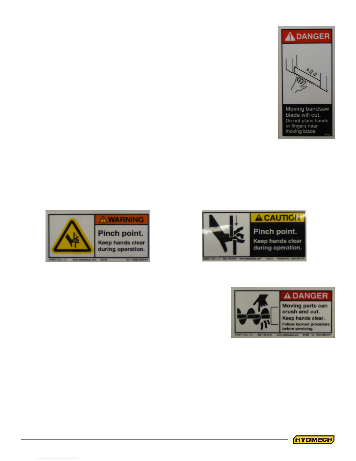
MOVING BANDSAW BLADE WILL CUT
Do NOT operate with guard removed.
Do NOT place hands or ngers near moving bandsaw blade.
For blade changing, always follow the proper Blade Changing Procedure, as given in
Section 3 of this manual.
PINCH POINT
Machine parts may move without warning, either because the machine is operating automatically, or because
another person initiates the motion. Keep hands clear of all labelled pinch points, whenever the machine is
running. Machine vises can exert great force and cause severe injury. Keep hands clear of vises and work piece
when vises are opened or closed. Be aware that vise closing or opening may result in potentially dangerous work
piece movement. Be aware also that the opening motion of a vise may create potential pinch points.
MOVING PARTS CAN CRUSH AND CUT
Keep hands clear of chip auger. Lock-out power in accordance with your
company’s lock-out procedures before attempting to clear a jam in the
chip auger.
Be aware that the chip auger may start unexpectedly, either because the
machine is operating automatically, or because another person initiates
the motion.
If the chip auger is stalled because of a jam, it may start without warning
when the jam is cleared, unless the machine power is locked out.
0.7

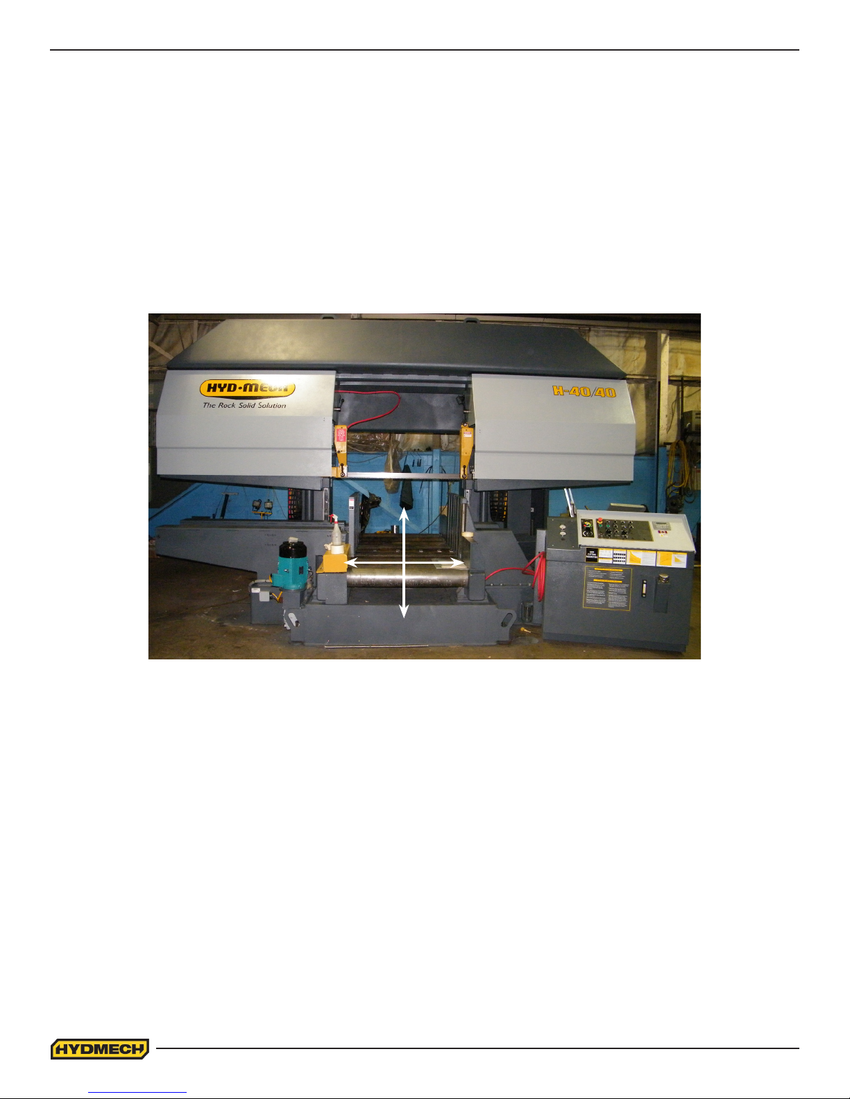
SECTION 1 - INSTALLATION
Upon delivery of your new H-40 saw, it is imperative that a thorough inspection be undertaken to check for any
damage that could have been sustained during shipping. Special attention should be paid to the electrical and
hydraulic systems to check for damaged cords, hoses and uid leaks. In the event of damage caused during
shipping, contact your carrier to le a damage claim.
SAFETY PRECAUTIONS
The H-40 has been designed to give years of reliable service. It is essential that operators be alerted to the
safe operation of this saw, and the practices to avoid that could lead to injury. The following safety rules are at
the minimum necessary for the safe installation, operation, and maintenance of the saw. Take every precaution
for the protection of operators and maintenance personnel. At the beginning and through out this manual there
are precautionary indicators, these will inform you of areas which require special attention.
• POWER HOOK-UPS AND REPAIRS SHOULD BE ATTEMPTED ONLY BY QUALIFIED TRADESMEN.
• THE SAW SHOULD BE LOCATED IN AN AREA WITH SUFFICIENT ROOM TO SAFELY LOAD STOCK
INTO THE SAW. SECURE THE SAW TO THE FLOOR.
• THE AREA AROUND THE SAW SHOULD BE MAINTAINED IN A CLEAN AND TIDY CONDITION TO
AVOID OBSTACLES OPERATORS COULD TRIP OVER.
• THE H-40 SAW SHOULD ONLY BE OPERATED ACCORDING TO THE SPECIFICATIONS OF THE
SAW AVOID UNSAFE USAGE PRACTICES.
• IF AT ANY TIME THE SAW DOES NOT APPEAR TO BE OPERATING PROPERLY IT SHOULD BE
STOPPED IMMEDIATELY AND REPAIRED.
OPERATOR:
• THE SAW SHOULD NEVER BE OPERATED UNLESS ALL GUARDS AND DOORS ARE IN PLACE AND
CLOSED.
• KEEP A SAFE DISTANCE FROM ALL MOVING PARTS – ESPECIALLY THE BLADE AND VISES.
• LOOSE CLOTHING AND GLOVES SHOULD NEVER BE WORN WHILE OPERATING THE SAW,
COVER LONG HAIR.
• STOCK SHOULD NOT BE LOADED ONTO THE SAW IF THE BLADE IS RUNNING.
• LONG AND HEAVY STOCK SHOULD ALWAYS BE PROPERLY SUPPORTED IN FRONT OF AND
BEHIND THE SAW.
• NEVER ATTEMPT TO DISLODGE OR MOVE STOCK WHILE THE BLADE IS MOVING. TAKE THE
TIME TO STOP THE SAW BLADE, REMOVE OBSTRUCTIONS, AND RESTART BLADE.
• MUST WEAR EYE PROTECTION.
• MAINTAIN PROPER ADJUSTMENT OF BLADE TENSION, BLADE GUIDES, AND BEARINGS.
• HOLD WORKPIECE FIRMLY AGAINST TABLE.
• DO NOT REMOVE JAMMED CUTOFF PIECES UNTIL BLADE HAS STOPPED.
NO MODIFICATIONS TO THE MACHINE ARE PERMITTED WITHOUT PRIOR APPROVAL FRO HYD-MECH. ANY
APPROVED MODIFICATIONS SHOULD ONLY BE UNDERTAKEN BY TRAINED PERSONNEL.
1.1
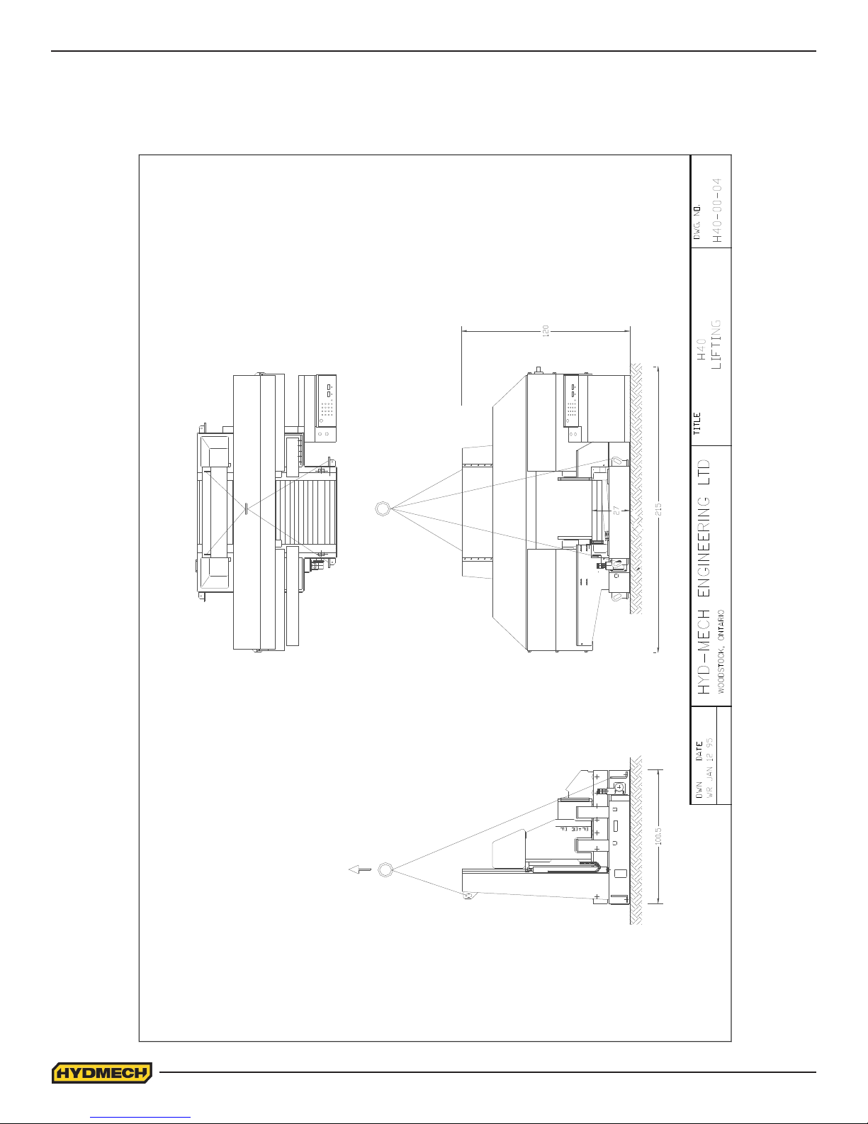
LIFTING THE H-40
The machine weight for a H40-40 is 39,000lbs (17690Kg) or 42,000lbs (19051Kg) with the optional outboard vise.
The machine weight for a H40-60 is 42,000lbs (19051Kg) or 45,000lbs (20412Kg) with the optional outboard vise.
The machine weight for a H40-80 is 46,000lbs (20865Kg) or 50,000lbs (22680Kg) with the optional outboard vise.
1.2
THE DATA/DESIGN CONTAINED HEREIN IS PROPRIETARY
AND CONFIDENTIAL.REPRODUCTION,PUBLICATION OR
DISTRIBUTION OF ANY PART REQUIRES WRITTEN CONSENT
OF HYD-MECH GROUP.THIS DATA IS THE PROPERTY OF
HYD MECH GROUP AND ITS POSSESION CONFERS NO
LICENSE TO USE OR RIGHT OR LICENSE TO DISCLOSE IT
TO OTHERS FOR ANY PURPOSE WHATSOEVER.
ALL RIGHTS RESERVED.
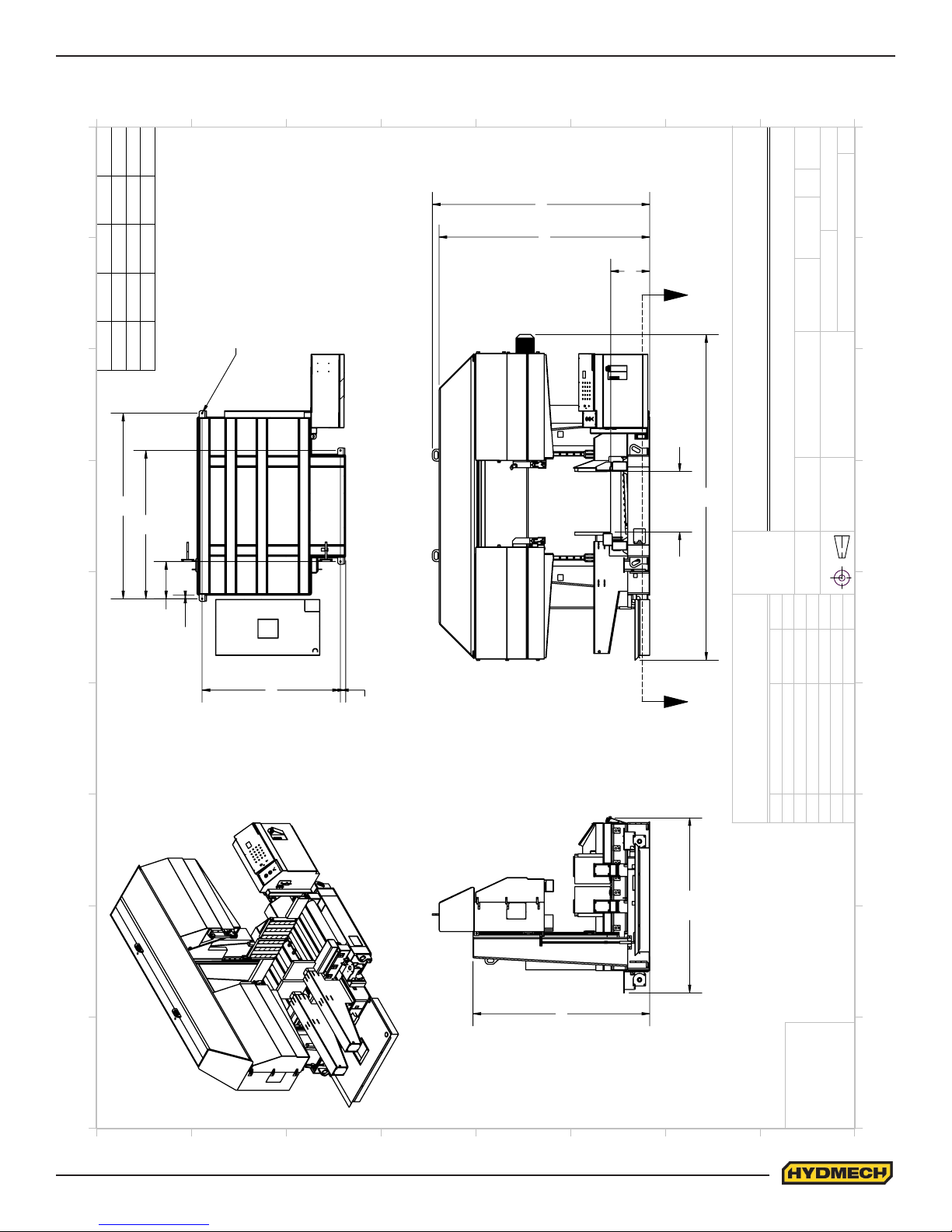
MACHINE LAYOUT
8
J
126"
146"
100.75"
120.75"
I
221"
241"
A B C D
41"
61"
H
H4040
H4060
166"
140.75"
261"
81"
H4080
7
6
1-8 UNC (x4)
5
4
3
148
143
27
2
1
SHEET
SCALE
CHKED BY:
1
OF
1
1:66
DATE:
COATING:
0
REV
-
No Coating
J
I
H40-0-00
AA
EngCoop
Jan 21, 2016
DRWN BY:
PART WEIGHT:
DRAWING NUMBER:
DATE:
WOODSTOCK. ONTARIO. CANADA N4S 0A9
H
HYDMECH GROUP LIMITED
MAT'L:
COMPONENT GROUP:
G
B
D
C
SECTION A-A
A
00 - Top Level
MODEL:
H4040
TITLE
H4040, H4060, H4080 MACHINE LAYOUT
G
MATERIAL CODE:
FOUNDATION PLAN
F
UNLESS
HYDMECH
STANDARD
TOLERANCES
SPECIFIED
OTHERWISE
DIMENSIONS
-
-
BY
ARE IN INCHES
THIRD ANGLE PROJECTION
F
25.25
2.5
E
DATE
-
-
E
94
3.5
REVISIONS
-
-
ECN NUMBER
D
C
B
120
119
REV
-
-
D
C
B
A
8
7
6
5
4
3
2
1
A
0
1.3
FOUNDATION, LEVELING AND ANCHORING
Machine location should be carefully selected. A at concrete oor area should be chosen. It should have enough free
space surrounding the machine to enable free access for safe operation and maintenance.
The machine should be leveled in both directions, i.e. along and across its infeed conveyor especially when machine is to
be inserted into a larger conveyor system. The photo below shows the conveyor from the infeed side.
Four leveling screws are provided, one in each corner of the machine base. Steel plates are to be placed under each
screw to prevent their sinking into the concrete oor.
NOTES: In some cases leveling the saw infeed and auxiliary conveyors with a slight slope towards the blade are recommended. This will prevent coolant from running down the raw stock. (This is especially true when cutting tubing or bun-
dles).
H-40 INSTALLATION PROCEDURE
1) Machine location should be carefully selected. A at concrete oor area should be chosen and have enough free
space surrounding the machine to enable free access for safe operation and maintenance.
2) Cut strapping and remove conveyor drive & chip bucket from saw rollers.
3) Remove coolant tank & position at the left side of the saw (facing from front).
4) Remove leveling pads from inside coolant tank & place under saw base leveling bolts.
5) Check machine level from side to side & back to front. A slight incline (1/8”-1/4” rear of saw higher) will assist
coolant ow back into return tray. Ideally if the machine is sitting at on the oor & the level is good do not
touch leveling bolts. If leveling bolt adjustment is necessary use shims supplied and place under 6 corners of
base frame. Remove leveling bolts and re-check level. If level is unchanged anchor machine to the oor using
adjusting bolt holes.
6) Install infeed conveyor drive with bolts supplied. Install the conveyor drive chain.
1.4
For machine shipping purposes the following items have been removed from the saw.
• Infeed conveyor gearbox and motor
• Bearing housing support
• Chain guard
Once the machine has been installed, levelled and anchored the above three items are to be installed as follows:
1. Install the gearbox and motor (1) using the four bolts and use the gearbox as a tensioner by moving it up and
down before completely tightening the four bolts.
2. Install the chain guard over the sprockets.
3. Install the bearing housing support (2).
4. Install the chain guard (3).
3
1
2
1.5

HYDRAULIC OIL AND CUTTING FLUID
The H-40 bandsaw is supplied with Texaco 46 hydraulic oil. If it in necessary to change the oil to dierent brand see the
HYDRAULIC SECTION for equivalent grade oil.
No cutting uid is supplied with machine. There are two types of coolant available:
-Oil based; dilute 1:10 ratio. (one part concentrated coolant to 10 parts water)
-Synthetic; dilute as recommended by the manufacturer.
WIRING CONNECTIONS
After the machine is leveled and anchored the necessary power hook-up needs to be performed. In order to provide
a safe operation as well as to prevent potential damage to the machine, only qualied personnel should make the
connections.
BEFORE START-UP THE FOLLOWING TWO POINTS SHOULD BE CHECKED:
-Signs of damage that may have occurred during shipping to the electrical cables and the hydraulic hoses.
-The hydraulic oil level is between the upper and lower lines on the level gauge on the front of the control panel base.
As supplied, the machine is set to run on three phase voltage as indicated on the serial plate and voltage label. Power
connection to the machine is made to machine disconnect and ground connections inside the electrical panel as shown
below.
During the initial hook-up it is very important to check that the phase order is correct. This is indicated by the hydraulic
pressure gauge registering a pressure rise and the blade running in a counter clockwise direction. If the hydraulics do not
register an immediate pressure rise, shut the hydraulics o and change the phase order.
ATTENTION:
1) Running the hydraulics “backwards” can damage the hydraulic pump.
2) After checking the hydraulic pressure and BEFORE INSTALLING the drive chain between
the infeed conveyors, check that the conveyors are running in the correct direction. If they are
not, change any two phases at the MOTOR JUNCTION BOX for each motor as required.
Power connections should be made by qualied personnel only
1.6
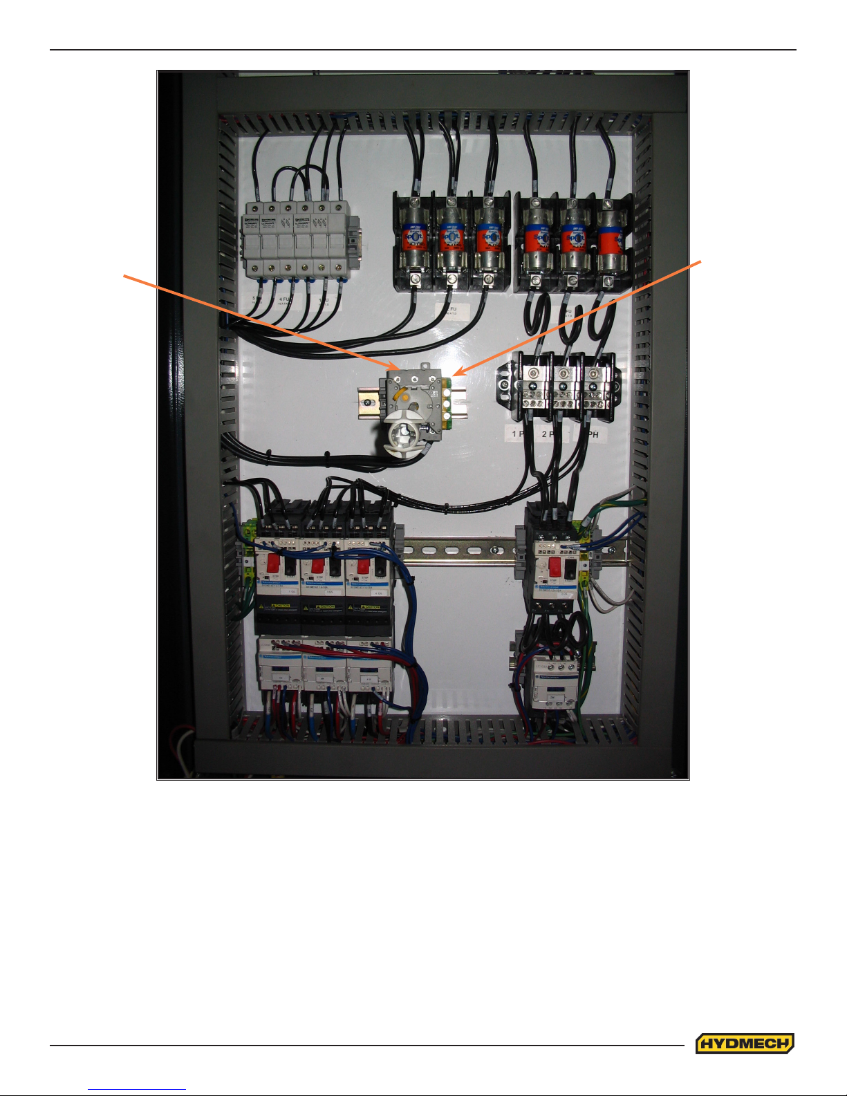
L1 L2 L3
Ground
connection
Electrical panel located
behind the head on the
drive side
1.7

SECTION 2 - OPERATING INSTRUCTIONS
This section has been prepared to give the operator the ability to set up the saw for most cutting situations. Before cutting
any material, the operator should be familiar with all operations and controls as well as the basic cutting theory described
below. The saw is equipped with variable blade speed and hydraulic feed control, as well as an extensive door chart to
guide the operator to the correct setting of these controls.
BLADE BASICS
Technology is rapidly changing all aspects of production machining. Metal cuto is no exception. The advances made
in the bandsaw blade industry have denitely brought down the cost per cut, despite the three fold higher price of high
technology blades. Variable pitch, bi-metal blades (like the 4/6 or 3/4 bi-metal blade supplied with the machine) last much
longer, cut faster, and more accurately than conventional carbon steel blades. In order to take advantage of the superiority
of bi-metal blades, it is critical to properly “break-in” a new blade. This is accomplished by taking two or three cuts through
solid four or ve inch diameter mild steel at an extremely slow feed rate. (It is also advisable to utilize a slow blade speed)
These two or three slow cuts suciently lap (polish) the teeth on the new blade so that it does not snag the material being
cut. Proper break-in will alleviate blade vibration; improve surface nish, accuracy, and blade life.
After “break-in”, the following six points must be closely monitored to ensure long blade life:
1. Proper blade tension should be maintained. (See Section 3, Maintenance and Troubleshooting)
2. Generous coolant application is essential with most materials. A high quality and well mixed coolant will extend
blade life, and also increase cutting rate and quality. On those materials where coolant is undesirable for cutting,
a slight coolant ow or periodic oiling of the blade is necessary to prevent the blade from being scored by the
carbide guides.
3. The stock being cut must be securely clamped in the vises.
4. The proper feed force should be chosen. (see Saw Cutting Parameters: Step 2)
5. The proper blade speed must be selected. (see Saw Cutting parameters: Step 4)
6. The proper feed rate must be applied. (see Saw Cutting Parameters: Step 5)
VARIABLE SPEED CONTROL
Blade speed can be adjusted innitely between 75 and 270 SFM (Surface Feet/Minute) (23 to 82 m/min) Adjustment
should be made only when the blade is running. Clockwise rotation of the knob increases blade speed while counter
clockwise rotation decreases blade speed.
THE CONTROL PANEL
START-UP
The control console has been designed to simplify the operation of the saw, to give the operator the ability to stop any
function at any time, and to be able to control all the functions remotely. We cannot overstress the importance of
familiarizing yourself with the controls prior to star ting the machine.
NOTE:
1. ALL SWITCHES MUST BE IN THE CENTER NEUTRAL POSITION TO START THE MACHINE!
2. WHEN STARTING THE MACHINE FOR THE FIRST TIME MAKE SURE THAT BLADE IS MOVING IN A
COUNTERCLOCKWISE DIRECTION, AND THAT THE HYDRAULIC PRESSURE IS:
-1200 PSI FOR H-40/40 AND H-40/60
-1300 PSI FOR H-40/80
MANUAL OPERATION
Manual Operations can be performed by using the control buttons on the HMI. All functions are self-explanatory. Specic
control button functions are described on the following pages.
2.1
 Loading...