

Hyd-Mech H18A-120, H22A-120 User Manual
H18A-120 & H22A-120
Thank you,
On behalf of everyone at HYD·MECH Group Limited, we would like to thank and congratulate you on your decision to
purchase a HYD·MECH bandsaw.
Your new machine is now ready to play a key role in increasing the efciency of your operation, helping you to reduce cost
while boosting quality and productivity.
To ensure you are maximizing the power and versatility of your new HYD·MECH bandsaw, please take the time to
familiarize yourself and your employees with the correct operation and maintenance procedures as outlined in this
manual.
We sincerely appreciate the condence you have demonstrated in purchasing our product and look forward to building a
long and mutually benecial relationship.
Thank you
Hyd·Mech Group Limited
P.O. Box 1659, 1079 Parkinson Road
Woodstock, Ontario, N4S 0A9
Phone : (519) 539-6341
Service : 1-877-237-0914
Sales : 1-877-276-SAWS (7297)
Fax : (519) 539-5126
e-mail : info@hydmech.com
PRINTED DEC 2013
1

2

TABLE OF CONTENTS
SECTION 0 - SAFETY INSTRUCTIONS
SUMMARY .......................................................................................................................................0.1
BASIC RULES ..................................................................................................................................0.3
RESPONSIBILITIES OF THE OWNER ............................................................................................0.3
RESPONSIBILITIES OF THE OPERATOR AND MAINTENANCE PERSONNEL ...........................0.4
SAFETY HAZARD LABELS .............................................................................................................0.6
SECTION 1 - INSTALLATION
SAFETY PRECAUTIONS .................................................................................................................1.1
FOUNDATION, LEVELLING AND ANCHORING .............................................................................1.2
BARFEED INSTALLATION ..............................................................................................................1.2
MACHINE GUARD INSTALLATION .................................................................................................1.8
WIRING CONNECTIONS ................................................................................................................1.10
EARTH GROUNDING PROCEDURE .............................................................................................1.10
HYDRAULIC OIL AND CUTTING FLUID ........................................................................................1.10
SECTION 2 - OPERATING INSTRUCTIONS
BLADE BASICS................................................................................................................................2.1
VARIABLE SPEED CONTROL.........................................................................................................2.1
THE CONTROL PANEL ...................................................................................................................2.1
START-UP ........................................................................................................................................2.1
PLC 100 CONTROL SYSTEM .........................................................................................................2.2
MANUAL MODE ...............................................................................................................................2.5
SINGLE CUT MODE OPERATION ..................................................................................................2.6
AUTOMATIC OPERATION ...............................................................................................................2.7
WORKING WITH A QUEUE .............................................................................................................2.8
WORKING WITH A REPEATING QUEUE .......................................................................................2.8
PARAMETERS .................................................................................................................................2.9
HYDRAULIC FEED CONTROL .......................................................................................................2.11
CUTTING PARAMETERS CHART ..................................................................................................2.12
ADDITIONAL CONTROLS ..............................................................................................................2.18
COOLANT FLOW ............................................................................................................................2.18
HEAD UP AND DOWN LIMIT SETTING .........................................................................................2.19
VARIABLE VISE PRESSURE (OPTION) .......................................................................................2.19
BUNDLING OPERATION (OPTION) ..............................................................................................2.20
i

SECTION 3 – MAINTENANCE
SAFETY DURING MAINTENANCE AND TROUBLESHOOTING ....................................................3.1
LOCK OUT PROCEDURE ...............................................................................................................3.1
BLADE CHANGE MODE PROCEDURE ..........................................................................................3.2
BLADE REMOVAL............................................................................................................................3.3
BLADE INSTALLATION ....................................................................................................................3.3
BLADE BRUSH ADJUSTMENT .......................................................................................................3.4
BLADE TRACKING ADJUSTMENT .................................................................................................3.4
IDLER WHEEL TRACKING .............................................................................................................3.4
DRIVE WHEEL TRACKING .............................................................................................................3.5
GEARBOX LUBRICATION (H18ASV - A503 GEARBOX, H22ASV - A603 GEARBOX) .................3.5
OUTPUT SHAFT LUBRICATION .....................................................................................................3.5
CAM FOLLOWER ADJUSTMENT ...................................................................................................3.6
LUBRICATION ..................................................................................................................................3.6
HYDRAULIC MAINTENANCE ..........................................................................................................3.7
CLEANLINESS .................................................................................................................................3.7
TROUBLESHOOTING .....................................................................................................................3.8
PLC TROUBLESHOOTING ............................................................................................................3.10
M12 PIN ASSIGNMENTS FOR I/P & O/P DEVICES ......................................................................3.12
STANDARD PARAMETER VALUES ...............................................................................................3.14
ACTUAL PARAMETER VALUES ....................................................................................................3.16
SECTION 4 - ELECTRICAL
ELECTRICAL SCHEMATICS: SEE PDF ON ATTACHED CD .........................................................4.1
SECTION 5 - HYDRAULIC
HYDRAULIC SCHEMATICS & PLUMBING DIAGRAMS: SEE PDF ON ATTACHED CD ...............5.1
SECTION 6 - MECHANICAL ASSEMBLIES
MECHANICAL ASSEMBLY DRAWINGS & PARTS LIST: SEE PDF ON ATTACHED CD ................6.1
SECTION 7 - OPTIONS
OPTIONAL ASSEMBLY DRAWINGS: SEE PDF ON ATTACHED CD .............................................7.1
POWERED CONVEYOR - CONTROLS ..........................................................................................7.1
SECTION 8 - SPECIFICATIONS
H18A-120 SPECIFICATIONS ...........................................................................................................8.1
H18A-120 MACHINE LAYOUT ........................................................................................................8.2
H22A-120 SPECIFICATIONS ...........................................................................................................8.3
H22A-120 MACHINE LAYOUT ........................................................................................................8.4
H22A-120 with OV MACHINE LAYOUT ..........................................................................................8.5
WARRANTY .....................................................................................................................................9.1
SECTION 9 - WARRANTY
ii

SECTION 0 - SAFETY INSTRUCTIONS
SUMMARY
All persons operating this machine must have read and understood all of the following sections of this Manual:
Section 0 SAFETY
Section 2 OPERATING INSTRUCTIONS
However, as a memory aid, the following is a summary of the Safety Section.
Put Safety First
Mandatory Information – What operators and maintenance people must have read and understood.
Signatures – Everyone involved with this machine must sign to conrm they have read and understood mandatory
information.
Basic Rules – only use this machine when
• It is in good working order.
• All safety equipment is in place and functional.
• Operations are in compliance with this manual.
• Materials are within designed specications and are non-hazardous.
Owner is responsible to
• Keep Manual accessible at the machine.
• Ensure only reliable, fully trained personnel work with the machine.
• Clearly dene responsibilities of all personnel working with the machine.
• Keep the machine in good working order.
Operator and Maintenance Personnel are responsible to:
• Keep all safety equipment in order, check its function at the beginning of each shift, and report any shortcomings.
• Shut down machine and report any faults or malfunctions that could impair safety.
• Understand and obey safety hazard labels.
• Not to wear un-restrained long hair, loose clothing or jewellery.
• Wear all required personal protective equipment.
• Not to wear gloves within 24 inches of moving blade.
• Maintain a clean working area and machine.
• Always use Lock-out when performing maintenance or repairs.
0.1

FOREWORD
Put Safety First!
This Safety Section contains important information to help you work safely with your machine and describes the dangers
inherent to bandsaws. Some of these dangers are obvious, while others are less evident.
It really is important to PUT SAFETY FIRST. Make it a habit to consider the hazards associated with any action BEFORE
you do it. If you feel any uncertainty, stop and nd a safer approach to the action. If you’re still uncertain, ask for advice
from your supervisor.
The SAFETY FIRST approach is particularly necessary when you do something new, or different, and most people
instinctively recognize this, although impatience may still cause them to take unnecessary risks.
Danger also lurks in the routine task that we have done over and over. Here, familiarity, boredom, or tiredness may lull us
into unthinking, automatic repetition. Be alert for this, and when you feel it happening, stop and take stock of your
situation. Review the safety hazards associated with what you are doing. That should get your brain working again.
Certainly production is important, but if you think you’re too busy to put safety rst, think how much production you’ll lose if
you get hurt.
You owe it to yourself, your family, and your co-workers to PUT SAFETY FIRST.
Mandatory Information
All persons operating this machine must have read and understood all of the following sections of this Manual:
Section 0 SAFETY
Section 2 OPERATING INSTRUCTIONS
Personnel involved in installation and maintenance of the machine must have read and understood all sections of the
manual
Persons who have difculty reading, or for whom English is not their rst language, must receive particularly thorough
instruction.
Signatures
Everyone involved in operation of this machine must sign below to conrm that:
I have read and understood all parts of Section 0 – Safety, and Section 2 – Operating Instructions.
Name Date Signature
Everyone involved in the installation, inspection, maintenance, and repair of this machine must sign below to conrm that:
I have read and understood all parts of this Operation and Maintenance Manual.
Name Date Signature
0.2

BASIC RULES
Intended Use
Exclusion of Misuse
Liability
Our machines are designed and built in line with the state of the art, and specically in accordance with
American National Standards Institute Standard B11.10 Safety Requirements for Metal Sawing Machines.
However, all machines may endanger the safety of their users and/or third parties, and be damaged,
or damage other property, if they are operated incorrectly, used beyond their specied capacity, or for
purposes other than those specied in this Manual.
Misuse includes, for example:
Sawing hazardous materials such as magnesium or lead.
Sawing work pieces which exceed the maximum workload appearing in the Specications.
Operating the machine without all original safety equipment and guards.
The machine may only be operated:
When it is in good working order, and
When the operator has read and understood the Safety and Operating Instructions Sections of the
Manual, and
When all operations and procedures are in compliance with this Manual.
Hyd-Mech Group cannot accept any liability for personal injury or property damage due to operator errors
or non-compliance with the Safety and Operating Instructions contained in this Manual.
RESPONSIBILITIES OF THE OWNER
Organization of work
This Operation and Maintenance Manual must always be kept near the machine so that it is accessible to
all concerned.
The general, statutory and other legal regulations on accident prevention and environmental protection
must also be observed, in addition to the Manual material. The operators and maintenance personnel
must be instructed accordingly. This obligation also includes the handling of dangerous substances and
the provision and use of personal protective equipment.
Choice and qualication of personnel
Ensure that work on the machine is only carried out by reliable persons who have been appropriately
trained for such work.
Training
Everyone working on or with the machine must be duly trained with regard to the correct use of the
machine, the correct use of safety equipment, the foreseeable dangers that may arise during operation of
the machine, and the safety precautions to be taken.
In addition, the personnel must be instructed to check all safety devices at regular intervals.
0.3

Dene responsibilities
Clearly dene exactly who is responsible for operating, setting-up, servicing and repairing the machine.
Dene the responsibilities of the machine operator and authorize him to refuse any instructions by third
parties if they run contrary to the machine’s safety.
Persons being trained on the machine may only work on or with the machine under the constant
supervision of an experienced operator. Observe the minimum age limits required by law.
Condition of Machine and Workplace
Ensure that the machine and its safety equipment are kept in good working order.
Ensure that the work area is well lit, and protected from the elements, such as rain, snow, abrasive dust,
and extremes of temperature.
Ensure that the machine is installed with sufcient clearance around it for the safe loading and unloading
of work pieces.
RESPONSIBILITIES OF THE OPERATOR AND MAINTENANCE PERSONNEL
Safety equipment
All machines are delivered with safety equipment that must not be removed or bypassed during operation.
The correct functioning of safety equipment on the machine must be checked:
• At the start of every shift.
• After maintenance and repair work
• When starting for the rst time, and after prolonged shutdowns
Emergency Stop Button (E-Stops)
Always be aware of the location of the Emergency Stop Button(s). Do not allow material or objects to
block your access to an Emergency Stop.
Damage
If any changes capable of impairing safety are observed in the machine or its operation, such as damage,
malfunctions, or irregularities, then appropriate steps must be taken immediately, the machine switched
off, locked-out, and the fault reported to the responsible person.
Safe operation
The machine may only be operated when in good working order and when all protective equipment is in
place and operational.
Keep a safe distance from all moving parts – especially the blade and vises.
Stock should not be loaded onto the saw if the blade is running.
Long and heavy stock should always be properly supported in front of and behind the saw.
Faults
The machine must be switched off and locked-out before starting to remedy any faults.
Safety hazard labels
Safety hazard labels and other instructional labels on the machine must be observed. They must be
clearly visible and legible at all times. If they become damaged they must be replaced.
0.4

Clothing, jewellery, protective equipment
Personnel operating or working on the machine must not wear un-restrained long hair, loose-tting
clothes and dangling jewellery.
When operating or working on the machine, always wear suitable, ofcially tested personal protective
equipment such as safety glasses and safety boots and any other equipment required by plant
regulations.
Gloves
Experience has shown that careless use of gloves around machinery is a major factor in serious hand
injuries.
Gloves should not be worn when operating or adjusting the machine, except:
Wear protective gloves when handling bandsaw blades at blade changes.
Gloves may be worn when handling work pieces, only if the machine is in Manual Mode and the
bandsaw blade is not running.
If the machine is running in Auto Mode, and only if the cut parts are greater than 24 inches
long, it may be possible to safely wear gloves for handling the cut parts, but the wearer of the
gloves must never put his hands near the blade for any reason. If the cut parts are less than 24
inches long, it is required to arrange their automatic ow into a parts bucket or other suitable
arrangement to avoid the necessity to pick them off the machine by hand.
Hearing protection
Ear protection must be worn whenever necessary.
The level and duration of noise emission requiring hearing protection depends upon the national
regulations in the country in which the machine is being used.
The actual level of noise emission by band sawing machines depends upon work piece size, shape and
material, blade type, blade speed and feed rate.
The only practical course of action is to measure the actual noise emission levels for the type of work that
is typically done. With reference to national standards, decide upon the necessary hearing protection
required.
In the absence of such measurements, it is advisable for anyone exposed to long periods of moderate to
loud noise to wear hearing protection. It is important to understand that hearing loss is gradual and easily
goes un-noticed until it is serious and irreversible.
Workplace
A clear working area without any obstructions is essential for safe operation of the machine. The oor
must be level and clean, without any build-up of chips, off-cuts, coolant, or hydraulic oil.
The workplace must be well lit, and protected from the elements, such as rain, snow, abrasive dust, and
extremes of temperature
Nothing may ever be placed on, or leaned against the machine, with the obvious exception of the work
piece on the table and conveyor of the machine.
0.5

Master Disconnect
Lock-out the machine before undertaking any maintenance or repair work on it. ‘Lock-out’ refers switching
off the master electrical disconnect switch, and locking it out so that it cannot be switched on again
without authorization.
On Hyd-Mech machines the Master Disconnect Switch will be of one of four types:
• Rotary switch mounted in electrical control cabinet door and inter-locked with door.
• Rotary switch mounted on the side of the operator interface console.
• Lever switch mounted in separate box mounted on the machine.
• Supply disconnect switch supplied by user at installation and usually wall-mounted within sight of
the machine, depending upon local regulations.
In almost all jurisdictions, it is required that owners of industrial equipment establish and post
lock-out procedures. Know and use the lock-out procedures of your company or organization.
Residual Risks
The machine is still not completely de-energized if an electrical cabinet door type switch is
locked-out.
The line side of the disconnect switch itself remains energized.
Variable speed blade drives store dangerous voltage in their capacitors, and this requires time to
dissipate. After locking out power, wait 3 minutes before beginning to work on machine electrical
circuits.
If compressed air is supplied to the machine to power a mist lubrication system or other devices,
it should be disconnected, and any stored air pressure released before working on the machine.
The weight of individual machine components represents stored potential energy that can be
released if they fall when disconnected. Secure these components with adequate hoisting gear
before disassembly.
SAFETY HAZARD LABELS
The safety hazard labels attached to your machine represent important safety information to help you avoid personal injury
or death.
All supervisors, operators, and maintenance personnel must locate and understand the safety information associated with
each hazard label prior to operating or servicing the machine.
The safety hazard labels shown below are located at various positions on the machine to indicate possible safety hazards.
The location and re-order part number of all the safety labels associated with this particular model of bandsaw are indicated
at the end of this section of the manual. It is important to replace any safety hazard label that becomes damaged or illegible.
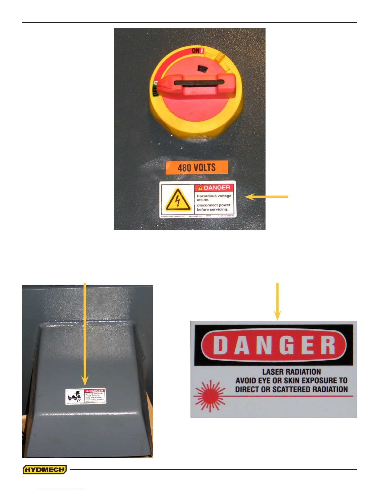
HAZARDOUS VOLTAGE INSIDE
Contact with high voltage may cause death or serious injury. Never perform
maintenance on, or near, electrical components until the machine’s electrical
power source has been disconnected. Lock-out power in accordance with your
company’s lock-out procedures before any such maintenance. The “Stop” or
“Emergency Stop” push button does not disconnect the machine’s power supply.
Hazardous voltage is still present in the machines electrical circuits.
The machine’s Electrical Disconnect Switch does disconnect voltage from the
machine’s circuits; however hazardous voltage is still present inside the main electrical cabinet, on the infeed (line) side of
the main fuses. Therefore keep hands and tools away from the infeed side of the control panel main fuses. If these fuses
need to be replaced, use a fuse puller.
Allow three minutes after locking-out power before opening any electrical enclosures. Your machine may be equipped with a
variable frequency drive that stores high voltage within its capacitors. Three minutes will allow sufcient time for this voltage
to safely discharge.
Never spray coolant directly at electrical components or cabinets.
0.6
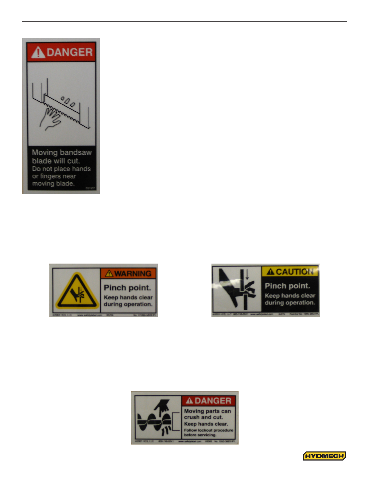
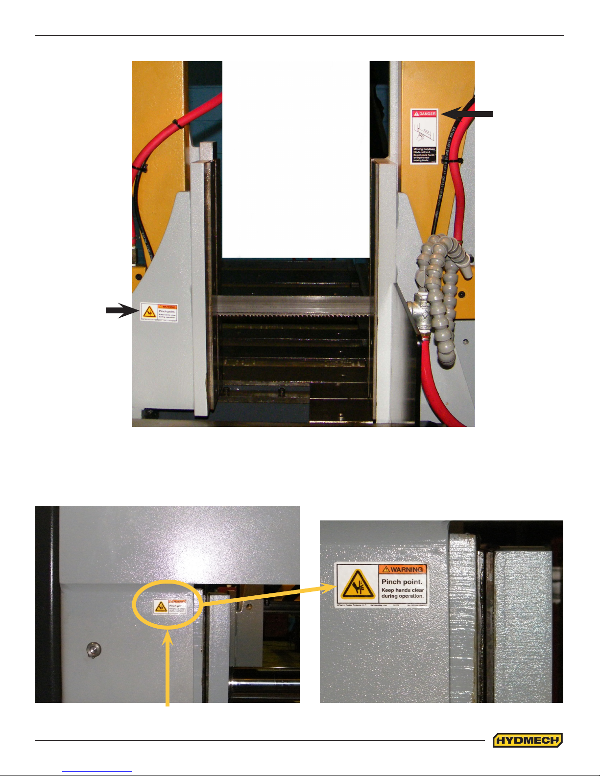
PINCH POINT
MOVING BANDSAW BLADE WILL CUT
Do NOT operate with guard removed.
Do NOT place hands or ngers near moving bandsaw blade.
For blade changing, always follow the proper Blade Changing Procedure, as given in
Section 3 of this manual.
Machine parts may move without warning, either because the machine is operating automatically, or because another
person initiates the motion. Keep hands clear of all labelled pinch points, whenever the machine is running. Machine vises
can exert great force and cause severe injury. Keep hands clear of vises and work piece when vises are opened or closed.
Be aware that vise closing or opening may result in potentially dangerous work piece movement. Be aware also that the
opening motion of a vise may create potential pinch points.
MOVING PARTS CAN CRUSH AND CUT
Keep hands clear of chip auger. Lock-out power in accordance with your company’s lock-out procedures before attempting
to clear a jam in the chip auger.
Be aware that the chip auger may start unexpectedly, either because the machine is operating automatically, or because
another person initiates the motion.
If the chip auger is stalled because of a jam, it may start without warning when the jam is cleared, unless the machine power
is locked out.
0.7
Chip Augar
Item #: 391335
Item #: 391938
Item #: 391340
0.8
Fixed Vise
Item #: 392801
Item #: 391397
Shuttle Vise
Item #: 392801
0.9

0.10

SECTION 1 - INSTALLATION
Upon delivery of your new H18A_H22A 120 saw, it is imperative that a thorough inspection be undertaken to check for any
damage that could have been sustained during shipping. Special attention should be paid to the electrical and hydraulic
systems to check for damaged cords, hoses and uid leaks. In the event of damage caused during shipping, contact your
carrier to le a damage claim.
SAFETY PRECAUTIONS
The machine has been designed to give years of reliable service. It is essential that operators be alerted to the safe operation of this saw and the practices to avoid that could lead to injury. The following safety rules are at the minimum necessary for the safe installation, operation, and maintenance of the saw. Take every precaution for the protection of operators
and maintenance personnel.
• POWER HOOK-UPS AND REPAIRS SHOULD ONLY BE ATTEMPTED BY QUALIFIED TRADESMEN.
• THE SAW SHOULD BE LOCATED IN AN AREA WITH SUFFICIENT ROOM TO SAFELY LOAD STOCK INTO
THE SAW. SECURE THE SAW TO THE FLOOR.
• THE AREA AROUND THE SAW SHOULD BE MAINTAINED IN A CLEAN AND TIDY CONDITION TO AVOID
OBSTACLES OPERATORS COULD TRIP OVER.
• THE H18A_H22A 120 SHOULD ONLY BE OPERATED ACCORDING TO THE SPECIFICATIONS OF THE SAW.
AVOID UNSAFE USAGE PRACTICES.
• IF AT ANY TIME THE SAW DOES NOT APPEAR TO BE OPERATING PROPERLY IT SHOULD BE
STOPPED IMMEDIATELY AND REPAIRED.
OPERATOR :
• THE SAW SHOULD NEVER BE OPERATED UNLESS ALL GUARDS AND DOORS ARE IN PLACE AND
CLOSED.
• KEEP A SAFE DISTANCE FROM ALL MOVING PARTS - ESPECIALLY THE BLADE AND VISES.
• LOOSE CLOTHING AND GLOVES SHOULD NEVER BE WORN WHILE OPERATING THE SAW. COVER LONG
HAIR.
• STOCK SHOULD NOT BE LOADED ONTO THE SAW IF THE BLADE IS RUNNING.
• LONG AND HEAVY STOCK SHOULD ALWAYS BE PROPERLY SUPPORTED IN FRONT OF AND BEHIND THE
SAW.
• NEVER ATTEMPT TO DISLODGE OR MOVE STOCK WHILE THE BLADE IS MOVING. TAKE THE TIME TO
STOP THE SAW BLADE, REMOVE OBSTRUCTIONS, AND START THE BLADE.
• MUST WEAR EYE PROTECTION.
• MAINTAIN PROPER ADJUSTMENT OF BLADE TENSION, BLADE GUIDES, AND BEARINGS
• HOLD WORKPIECE FIRMLY AGAINST TABLE.
• DO NOT REMOVE JAMMED CUTOFF PIECES UNTIL BLADE HAS STOPPED.
NO MODIFICATIONS TO THE MACHINE ARE PERMITTED WITHOUT PRIOR APPROVAL FROM
HYD-MECH. ANY APPROVED MODIFICATIONS SHOULD ONLY BE UNDERTAKEN BY TRAINED PERSONNEL.
1.1
FOUNDATION, LEVELLING AND ANCHORING
J
I
H
G
F
E
D
8
7
6
5
4
3
2
The machine location should be carefully selected. A at
concrete oor area should be chosen. It should have
enough free space surrounding the machine to enable
free access for safe operation and maintenance.
Machine should be leveled in both directions i.e. along
and across its in-feed conveyor especially when machine
is to be inserted into a larger conveyor system.
Six leveling screws are provided, one in each corner of
the machine base plus one in the hydraulic cabinet. Steel
plates are to be placed under each screw to prevent their
sinking into the concrete oor. In cases where the machine is to be anchored permanently, anchoring holes are
provided. They are located next to the leveling screws.
NOTE:
In some cases leveling the saw in-feed and auxiliary conveyor with a slight slope towards blade is recommended.
This will prevent coolant from running down the raw stock.
(This is especially true when cutting tubing or bundles).
BARFEED INSTALLATION
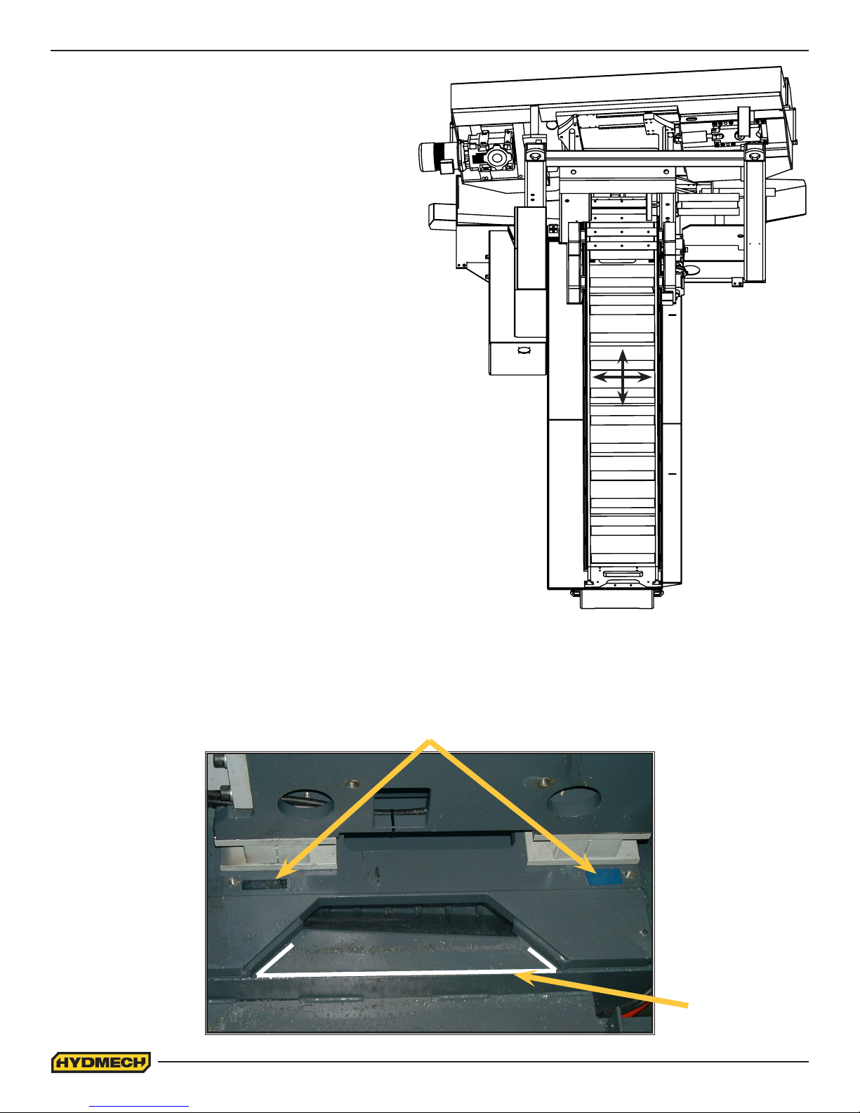
1. Prepare the machine base for mating with the barfeed. Place shims into position and place a bead of silicone on
the surfaces shown below.
Shim
1.2
Bead of
silicone
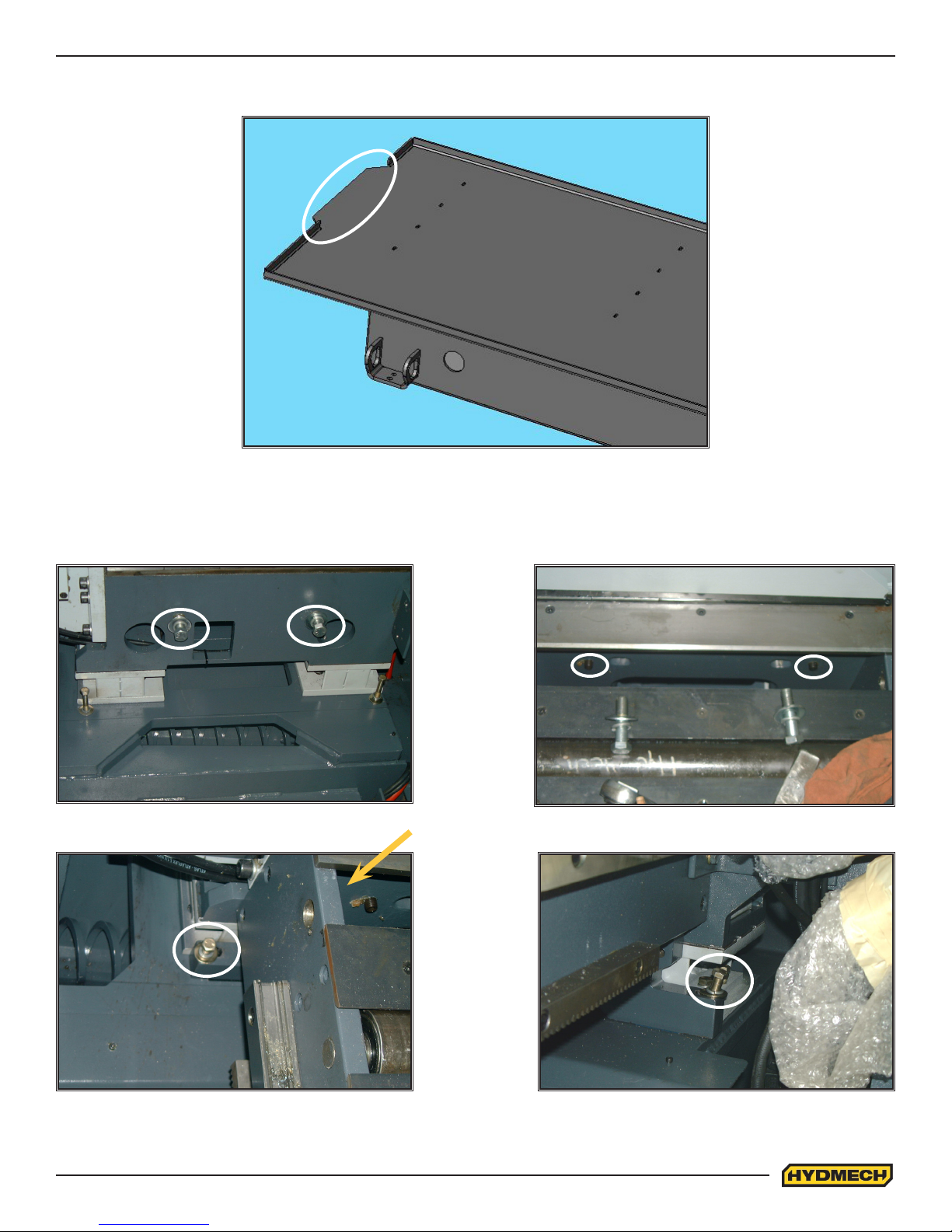
2. Move the barfeed into its proper position in relation to the machine. Make sure the lip of the conveyor seals properly with the bead of silicone.
3. Position the mounting holes of the front - end bracket of the barfeed. First fasten the two horizontal hex head
bolts (The two socket set screws are used to align the barfeed), and then tighten the two vertical hex bolts.
Horizontal hex bolts Socket set screws
Barfeed front end
bracket
Vertical hex bolts of
front end bracket
1.3

4. Fill all gaps between the barfeed and machine base with silicone.
Fill gaps on both
sides of the
barfeed.
5. Fasten the drip pan between the barfeed and machine base. Use a sheet of cork to make a gasket for the drip
pan.
Drip pan
Make a gasket to seal this surface (Do the
same for the other side of the conveyor)
6. The barfeed should be levelled in both directions i.e. along and across its in-feed conveyor. Six levelling screws
are provided, three down each length of the conveyor. Steel plates are to be placed under each screw to prevent
their sinking into the concrete oor. In cases where the machine is to be anchored permanently, anchoring holes
are provided. They are located next to the levelling screws.
NOTE: Levelling the barfeed with a slight slope towards the blade will prevent coolant from running down the raw
stock.
1.4
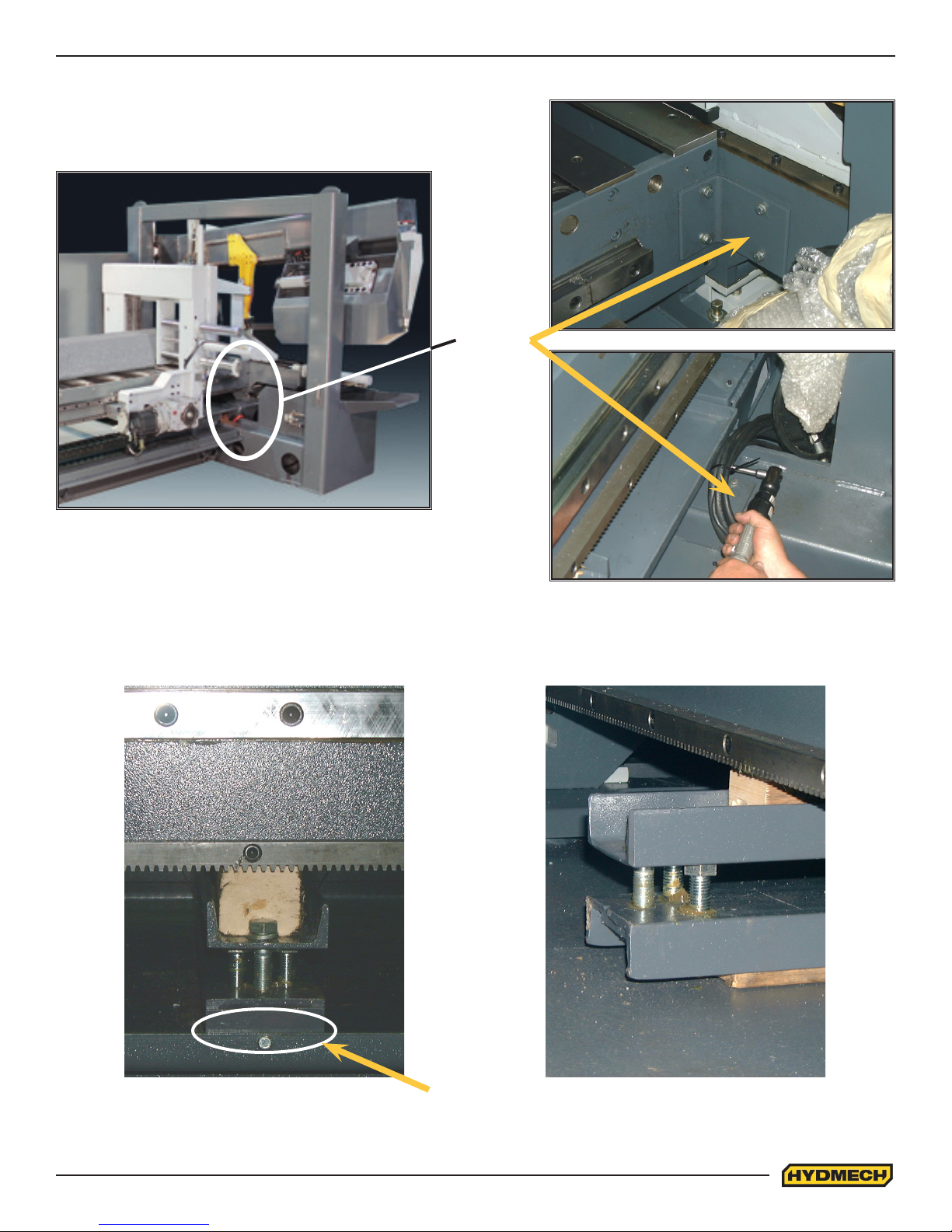
7. The barfeed support brackets should be fastened once it is levelled and anchored.
Brackets
8. The shipping supports must be removed once the barfeed is fastened to the machine.
The conveyor support is bolted and tack welded to the table; therefore, the welds must be ground off and the bolts
removed in order to disassemble the support.
Tack welded
2 spots
1.5
Two brackets support the shuttle vise for shipping, one on each side of the conveyor. Make sure they are removed
before attempting to move the shuttle.
Shuttle support brackets
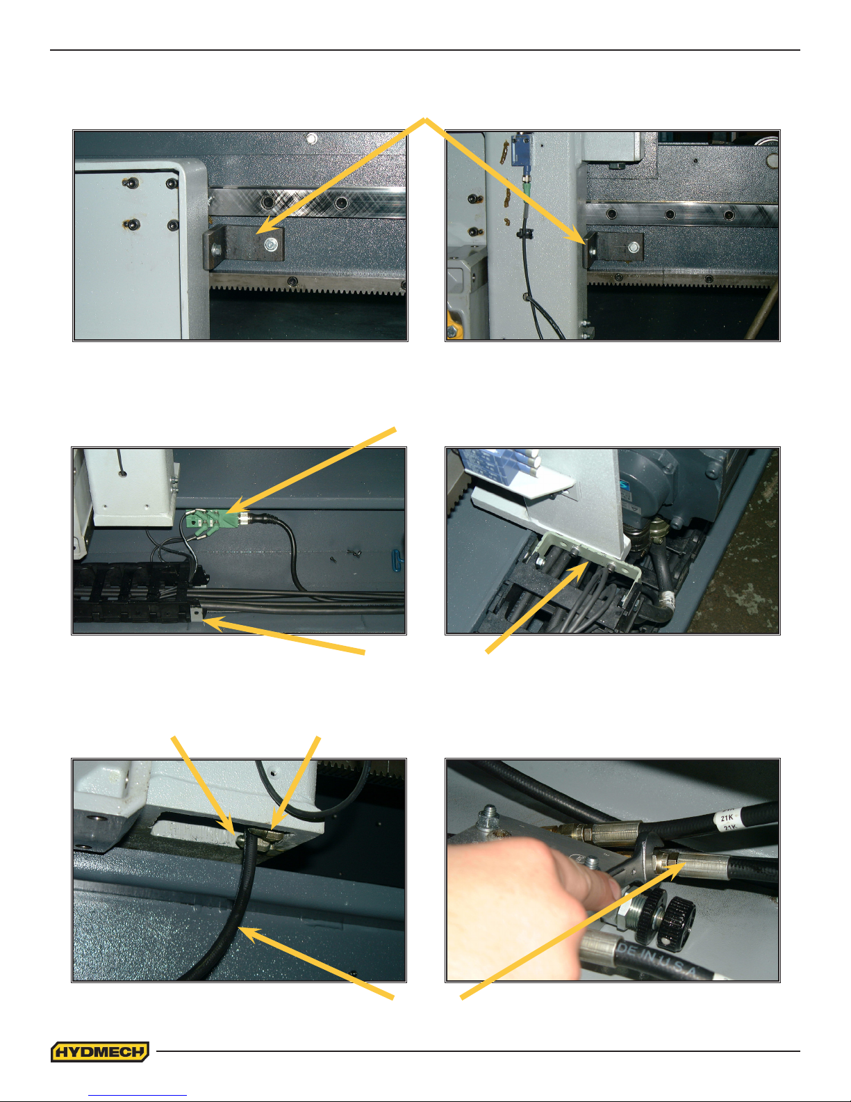
9. Remove the three cable covers that line the barfeed table. Unpack and unravel the cable track holding the wires
and hoses for the barfeed shuttle. Fasten the two brackets that will hold the cable track in place. The M12 port
can now be fastened to the barfeed table.
M12 port
Mounting brackets
10. Feed hydraulic hose #21L up through the shuttle frame and attach to the valve as shown below. Hose #21 and
#22 are to be connected at the bottom of the shuttle frame.
Hose 22Hose 21
Hose 21L
1.6
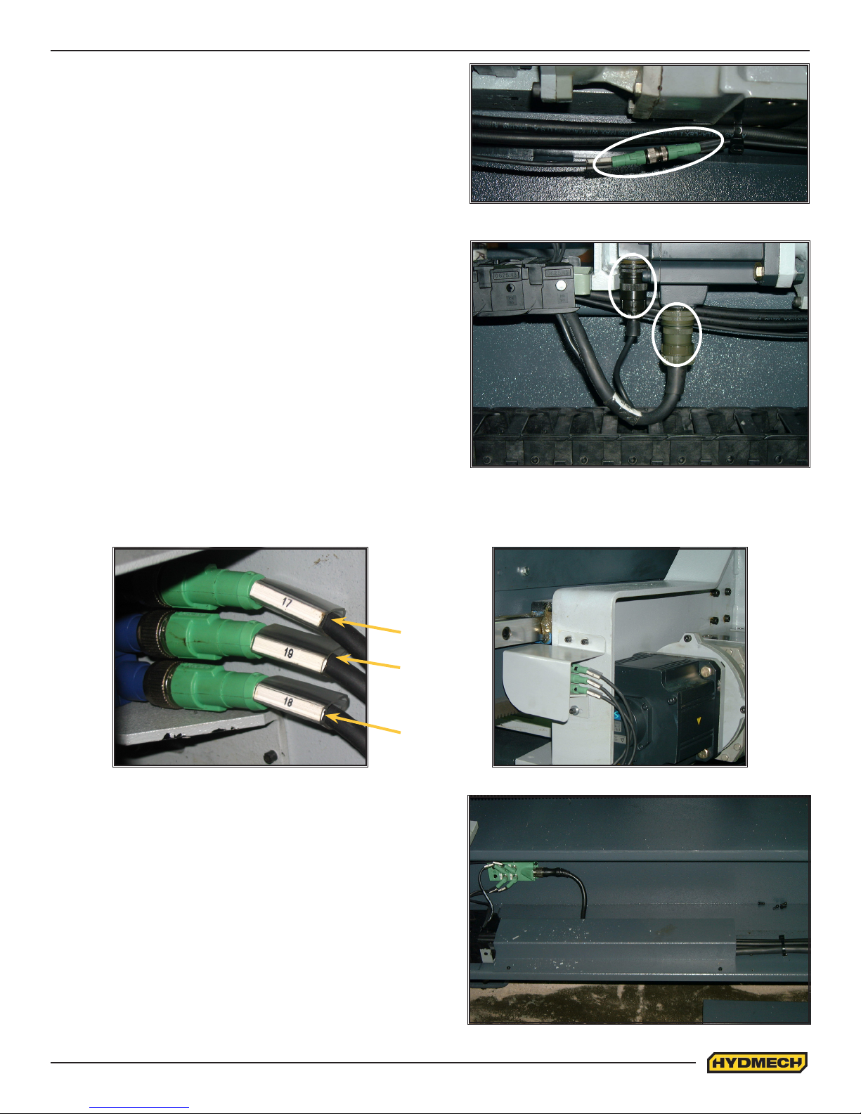
11. The M12 connector of wire #23 is to be connected under
the gearbox.
12. The two wire connections of the servo motor can now be
connected.
13. Connect wire #17, #18, and #19 to the limit switches attached to the shuttle vise frame. Make sure the cover
plate is secure and in the proper position.
Cable #17
Cable #19
Cable #18
14. Layout the wires and cables onto the barfeed table and
then fasten the three covers into place.
1.7
MACHINE GUARD INSTALLATION
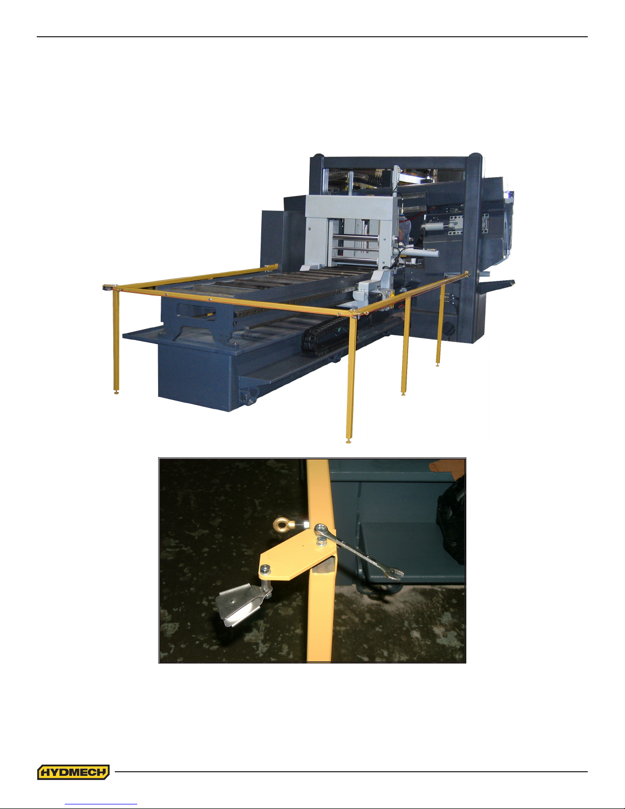
15. Position the three pieces of the safety guard around the barfeed. The idler side guard is connected to the machine column by a hex bolt. The drive side guard is connected to the control box by a hex bolt. The rear guard is
connected to the rear of the barfeed frame with two hex bolts.
A pulley is mounted on a bracket and attached
to each rear corner of the safety guard.
1.8
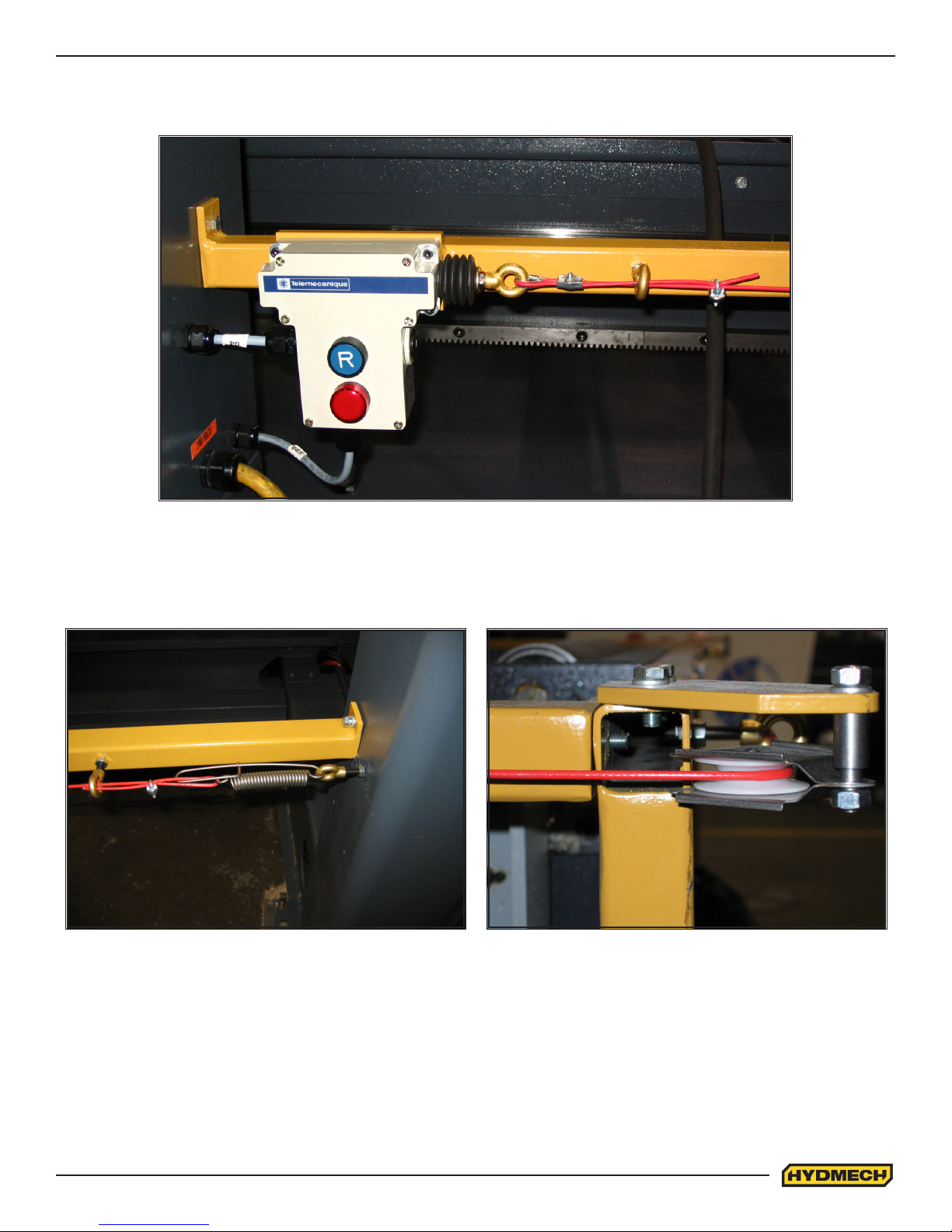
16. Fasten the trip wire control box to the safety guard and complete the wire connections (see schematics). The
box is attached to the mounting plate with four socket head cap screws. The plate is mounted to the safety guard
with two hex bolts.
17. Attach the eyebolt to the idler side column. Fasten the wire rope to the spring and then proceed to feed it through
the eyebolts and pulleys along the guardrail. Loop the other end of the wire rope around the eyebolt of the trip
wire control box. Tighten or loosen the idler side column eyebolt to adjust the tension on the wire rope. The
switch cannot be activated if there is not enough tension on the wire rope.
1.9

WIRING CONNECTIONS
After the machine is leveled and anchored the necessary power hook-up needs
to be performed. In order to provide safe operation as well as to prevent potential
damage to the machine, only qualied personnel should make the connections.
BEFORE START-UP THE FOLLOWING TWO POINTS SHOULD BE CHECKED:
1. Signs of damage that may have occurred during shipping to the electrical
cables and the hydraulic hoses.
2. The hydraulic oil level is between the upper and lower lines on the level
gauge.
As supplied, the machine is set to run on three phase voltage as indicated on the
serial plate and voltage label.
Power connection to the machine is made to L1, L2, L3 and Ground terminals in the main electrical box found beside the
conveyor on the drive side. For machines equipped with a variable frequency drive unit, an earth ground is also recommended.
During the initial hook-up it is very important to check that the phase order is correct. This is indicated by the hydraulic
pressure gauge registering a pressure rise and the blade running in a counter clockwise direction. If the hydraulics do not
register an immediate pressure rise, shut the hydraulics off and change the phase order.
ATTENTION: Running the hydraulics “backwards” can damage the hydraulic pump.
EARTH GROUNDING PROCEDURE
1. Customer to provide and install a ground rod approx. 60 (15mm) diameter, copper clad steel, to be driven no less
than 8’ (2.5m) into the ground, no more than 10’ (3m) away from control enclosure.
2. Ground rod to be connected to customer’s in plant ground system. This connection shall be made directly at the
ground rod (if applicable).
3. It is desirable that the overall resistance to ground measured at the ground rod does not exceed 3 ohms. Customer is advised to consult local power company for further information on grounding.
4. Ground rod to be connected to ground terminal in control enclosure using insulated, 8 AWG stranded copper wire.
An additional point to check is ensuring continuity of ground within control enclosure. Start with main power entrance
ground terminal where internal ground conductors should originate and connect to, DIN terminal strip, control transformer
and the lid of control enclosure. Also PLC and Interface units should have their own ground conductors connected to one
of the main ground terminals.
Properly functioning ground system will;
• Provide safety for personnel.
• Ensure correct operation of electrical/electronic devices.
• Prevent damage to electrical/electronic apparatus.
• Help dissipate lightning strokes.
• Divert stray radio frequency (RF) energy from electronic/control equipment.
HYDRAULIC OIL AND CUTTING FLUID
The H18A_H22A 120 bandsaw is supplied with Texaco Rando HD46 hydraulic oil. If it is necessary to change the oil to a
different brand see the HYDRAULIC SECTION for equivalent grade oil.
No cutting uid is supplied with the machine. There are two types of coolant available:
• Oil based; dilute 1:10 ratio (one part concentrated coolant to 10 parts water)
• Synthetic; dilute as recommended by the manufacturer.
1.10
 Loading...