

Page 1

H18 A & H22 A
395598
REV G
THANK YOU,
On behalf of everyone at HYD·MECH Group Limited, we would like to thank and congratulate you on your decision to
purchase a HYD·MECH bandsaw.
Your new machine is now ready to play a key role in increasing the eciency of your operation, helping you to reduce cost
while boosting quality and productivity.
To ensure you are maximizing the power and versatility of your new HYD·MECH bandsaw, please take the time to
familiarize yourself and your employees with the correct operation and maintenance procedures as outlined in this
manual. Please keep this instruction manual for future reference in a known location and easily accessible to all users of
the device.
HYD·MECH oers a great variety of options, components, and features for its various models. Therefore, some of the
equipment described in this manual (various illustrations and drawings) may not be applicable to your particular machine.
The information and specications provided in this manual were accurate at the time of printing. HYD·MECH reserves the
right to discontinue or change specications or design at any time without notice and without incurring any obligation.
Thank you.
Hyd·Mech Group Limited
P.O. Box 1659, 1079 Parkinson Road
Woodstock, Ontario, N4S 0A9
Phone : (519) 539-6341
Service : 1-877-237-0914
Sales : 1-877-276-SAWS (7297)
Fax : (519) 539-5126
e-mail : [email protected]
Printed SEPTEMBER 2014
1
Page 2

Page 3

TABLE OF CONTENTS
SECTION 0 - SAFETY INSTRUCTIONS
SUMMARY .......................................................................................................................................0.1
BASIC RULES ..................................................................................................................................0.3
RESPONSIBILITIES OF THE OWNER ............................................................................................0.3
RESPONSIBILITIES OF THE OPERATOR AND MAINTENANCE PERSONNEL ...........................0.4
SAFETY HAZARD LABELS .............................................................................................................0.6
SECTION 1 - INSTALLATION
SAFETY PRECAUTIONS .................................................................................................................1.1
LIFTING INSTRUCTIONS ................................................................................................................1.2
FOUNDATION, LEVELLING AND ANCHORING .............................................................................1.3
WIRING CONNECTIONS .................................................................................................................1.3
EARTH GROUNDING PROCEDURE ..............................................................................................1.4
HYDRAULIC OIL AND CUTTING FLUID .........................................................................................1.4
SECTION 2 - OPERATING INSTRUCTIONS
BLADE BASICS................................................................................................................................2.1
VARIABLE SPEED CONTROL.........................................................................................................2.1
THE CONTROL PANEL ...................................................................................................................2.1
MANUAL OPERATION .....................................................................................................................2.1
PLC 100 CONTROL SYSTEMS .......................................................................................................2.4
OPERATION OVERVIEW ................................................................................................................2.4
FUNCTION KEY DESCRIPTIONS ...................................................................................................2.5
MANUAL MODE FUNCTION KEY DESCRIPTIONS .......................................................................2.5
SINGLE PART CYCLE OPERATION ...............................................................................................2.6
KERF CORRECTION .......................................................................................................................2.6
AUTOMATIC OPERATION ...............................................................................................................2.7
SHUTTLE EMERGENCY STOP ......................................................................................................2.9
HYDRAULIC FEED CONTROL ........................................................................................................2.9
CUTTING PARAMETERS CHART ..................................................................................................2.10
ADDITIONAL CONTROLS ..............................................................................................................2.16
COOLANT FLOW ............................................................................................................................2.16
HEAD UP and DOWN LIMIT SETTING ..........................................................................................2.17
VARIABLE VISE PRESSURE (OPTION) .......................................................................................2.17
BUNDLING OPERATION (OPTION) ..............................................................................................2.18
SECTION 3 – MAINTENANCE
SAFETY DURING MAINTENANCE AND TROUBLESHOOTING ....................................................3.1
LOCK OUT PROCEDURE ...............................................................................................................3.1
BLADE CHANGE MODE PROCEDURE ..........................................................................................3.2
BLADE REMOVAL............................................................................................................................3.3
BLADE INSTALLATION ....................................................................................................................3.3
BLADE BRUSH ADJUSTMENT .......................................................................................................3.4
i
Page 4

BLADE TRACKING ADJUSTMENT .................................................................................................3.4
IDLER WHEEL TRACKING ..............................................................................................................3.4
DRIVE WHEEL TRACKING .............................................................................................................3.5
GEARBOX LUBRICATION (H-18ASV A503 GEARBOX, H-22ASV A603 GEARBOX) ...................3.5
OUTPUT SHAFT LUBRICATION .....................................................................................................3.5
CAM FOLLOWER ADJUSTMENT ...................................................................................................3.6
LUBRICATION ..................................................................................................................................3.6
HYDRAULIC MAINTENANCE ..........................................................................................................3.7
CLEANLINESS .................................................................................................................................3.7
TROUBLESHOOTING .....................................................................................................................3.8
PROGAMMABLE LOGIC CONTROL ..............................................................................................3.10
PLC PARAMETERS ........................................................................................................................3.11
PLC TROUBLESHOOTING ............................................................................................................3.13
MITSUBISHI FX2N 48MR INPUTS AND OUTPUTS ......................................................................3.18
M12 PIN ASSIGNMENTS FOR I/P & O/P DEVICES .....................................................................3.19
PLC PARAMETER DEFINITIONS & VALUES ................................................................................3.22
SECTION 4 - ELECTRICAL
FOR ELECTRICAL SCHEMATICS SEE PDF ON ATTACHED CD ..................................................4.1
SECTION 5 - HYDRAULIC
HYDRAULIC SCHEMATICS AND PLUMBING DIAGRAMS: SEE PDF ON ATTACHED CD. .........5.1
HYDRAULIC COMPONENT LIST ....................................................................................................5.1
GLAND ASSEMBLIES......................................................................................................................5.2
PISTON ASSEMBLIES .....................................................................................................................5.2
SECTION 6 - MECHANICAL ASSEMBLIES
MECHANICAL ASSEMBLY DRAWINGS AND PARTS LIST: SEE PDF ON ATTACHED CD ...........6.1
SECTION 7 - OPTIONS
FOR OPTIONAL ASSEMBLY DRAWINGS SEE PDF ON ATTACHED CD ......................................7.1
SECTION 8 - SPECIFICATIONS
H-18 ASV BANDSAW SPECIFICATIONS ........................................................................................8.1
H-22 ASV BANDSAW SPECIFICATIONS ........................................................................................8.2
H18SV & H22SV LIFTING INSTRUCTIONS....................................................................................8.3
H18SV LAYOUT ...............................................................................................................................8.4
H22SV LAYOUT ...............................................................................................................................8.5
WARRANTY .....................................................................................................................................9.1
SECTION 9 - WARRANTY
ii
Page 5

SECTION 0 - SAFETY INSTRUCTIONS
SUMMARY
All persons operating this machine must have read and understood all of the following sections of this Manual:
Section 0 SAFETY
Section 2 OPERATING INSTRUCTIONS
However, as a memory aid, the following is a summary of the Safety Section.
Put Safety First
Mandatory Information – What operators and maintenance people must have read and understood.
Signatures – Everyone involved with this machine must sign to conrm they have read and understood mandatory
information.
Basic Rules – only use this machine when
• It is in good working order.
• All safety equipment is in place and functional.
• Operations are in compliance with this manual.
• Materials are within designed specications and are non-hazardous.
Owner is responsible to
• Keep Manual accessible at the machine.
• Ensure only reliable, fully trained personnel work with the machine.
• Clearly dene responsibilities of all personnel working with the machine.
• Keep the machine in good working order.
Operator and Maintenance Personnel are responsible to:
• Keep all safety equipment in order, check its function at the beginning of each shift, and report any shortcomings.
• Shut down machine and report any faults or malfunctions that could impair safety.
• Understand and obey safety hazard labels.
• Not to wear un-restrained long hair, loose clothing or jewellery.
• Wear all required personal protective equipment.
• Not to wear gloves within 24 inches of moving blade.
• Maintain a clean working area and machine.
• Always use Lock-out when performing maintenance or repairs.
0.1
Page 6

FOREWORD
Put Safety First!
This Safety Section contains important information to help you work safely with your machine and describes the dangers
inherent to bandsaws. Some of these dangers are obvious, while others are less evident.
It really is important to PUT SAFETY FIRST. Make it a habit to consider the hazards associated with any action BEFORE
you do it. If you feel any uncertainty, stop and nd a safer approach to the action. If you’re still uncertain, ask for advice
from your supervisor.
The SAFETY FIRST approach is particularly necessary when you do something new, or different, and most people
instinctively recognize this, although impatience may still cause them to take unnecessary risks.
Danger also lurks in the routine task that we have done over and over. Here, familiarity, boredom, or tiredness may lull us
into unthinking, automatic repetition. Be alert for this, and when you feel it happening, stop and take stock of your
situation. Review the safety hazards associated with what you are doing. That should get your brain working again.
Certainly production is important, but if you think you’re too busy to put safety rst, think how much production you’ll lose if
you get hurt.
You owe it to yourself, your family, and your co-workers to PUT SAFETY FIRST.
Mandatory Information
All persons operating this machine must have read and understood all of the following sections of this Manual:
Section 0 SAFETY
Section 2 OPERATING INSTRUCTIONS
Personnel involved in installation and maintenance of the machine must have read and understood all sections of the
manual
Persons who have difculty reading, or for whom English is not their rst language, must receive particularly thorough
instruction.
Signatures
Everyone involved in operation of this machine must sign below to conrm that:
I have read and understood all parts of Section 0 – Safety, and Section 2 – Operating Instructions.
Name Date Signature
Everyone involved in the installation, inspection, maintenance, and repair of this machine must sign below to conrm that:
I have read and understood all parts of this Operation and Maintenance Manual.
Name Date Signature
0.2
Page 7

BASIC RULES
Intended Use
Exclusion of Misuse
Liability
Our machines are designed and built in line with the state of the art, and specically in accordance with
American National Standards Institute Standard B11.10 Safety Requirements for Metal Sawing Machines.
However, all machines may endanger the safety of their users and/or third parties, and be damaged,
or damage other property, if they are operated incorrectly, used beyond their specied capacity, or for
purposes other than those specied in this Manual.
Misuse includes, for example:
Sawing hazardous materials such as magnesium or lead.
Sawing work pieces which exceed the maximum workload appearing in the Specications.
Operating the machine without all original safety equipment and guards.
The machine may only be operated:
When it is in good working order, and
When the operator has read and understood the Safety and Operating Instructions Sections of the
Manual, and
When all operations and procedures are in compliance with this Manual.
Hyd-Mech Group cannot accept any liability for personal injury or property damage due to operator errors
or non-compliance with the Safety and Operating Instructions contained in this Manual.
RESPONSIBILITIES OF THE OWNER
Organization of work
This Operation and Maintenance Manual must always be kept near the machine so that it is accessible to
all concerned.
The general, statutory and other legal regulations on accident prevention and environmental protection
must also be observed, in addition to the Manual material. The operators and maintenance personnel
must be instructed accordingly. This obligation also includes the handling of dangerous substances and
the provision and use of personal protective equipment.
Choice and qualication of personnel
Ensure that work on the machine is only carried out by reliable persons who have been appropriately
trained for such work.
Training
Everyone working on or with the machine must be duly trained with regard to the correct use of the
machine, the correct use of safety equipment, the foreseeable dangers that may arise during operation of
the machine, and the safety precautions to be taken.
In addition, the personnel must be instructed to check all safety devices at regular intervals.
0.3
Page 8

Dene responsibilities
Clearly dene exactly who is responsible for operating, setting-up, servicing and repairing the machine.
Dene the responsibilities of the machine operator and authorize him to refuse any instructions by third
parties if they run contrary to the machine’s safety.
Persons being trained on the machine may only work on or with the machine under the constant
supervision of an experienced operator. Observe the minimum age limits required by law.
Condition of Machine and Workplace
Ensure that the machine and its safety equipment are kept in good working order.
Ensure that the work area is well lit, and protected from the elements, such as rain, snow, abrasive dust,
and extremes of temperature.
Ensure that the machine is installed with sufcient clearance around it for the safe loading and unloading
of work pieces.
RESPONSIBILITIES OF THE OPERATOR AND MAINTENANCE PERSONNEL
Safety equipment
All machines are delivered with safety equipment that must not be removed or bypassed during operation.
The correct functioning of safety equipment on the machine must be checked:
• At the start of every shift.
• After maintenance and repair work
• When starting for the rst time, and after prolonged shutdowns
Emergency Stop Button (E-Stops)
Always be aware of the location of the Emergency Stop Button(s). Do not allow material or objects to
block your access to an Emergency Stop.
Damage
If any changes capable of impairing safety are observed in the machine or its operation, such as damage,
malfunctions, or irregularities, then appropriate steps must be taken immediately, the machine switched
off, locked-out, and the fault reported to the responsible person.
Safe operation
The machine may only be operated when in good working order and when all protective equipment is in
place and operational.
Keep a safe distance from all moving parts – especially the blade and vises.
Stock should not be loaded onto the saw if the blade is running.
Long and heavy stock should always be properly supported in front of and behind the saw.
Faults
The machine must be switched off and locked-out before starting to remedy any faults.
Safety hazard labels
Safety hazard labels and other instructional labels on the machine must be observed. They must be
clearly visible and legible at all times. If they become damaged they must be replaced.
0.4
Page 9

Clothing, jewellery, protective equipment
Personnel operating or working on the machine must not wear un-restrained long hair, loose-tting
clothes and dangling jewellery.
When operating or working on the machine, always wear suitable, ofcially tested personal protective
equipment such as safety glasses and safety boots and any other equipment required by plant
regulations.
Gloves
Experience has shown that careless use of gloves around machinery is a major factor in serious hand
injuries.
Gloves should not be worn when operating or adjusting the machine, except:
Wear protective gloves when handling bandsaw blades at blade changes.
Gloves may be worn when handling work pieces, only if the machine is in Manual Mode and the
bandsaw blade is not running.
If the machine is running in Auto Mode, and only if the cut parts are greater than 24 inches
long, it may be possible to safely wear gloves for handling the cut parts, but the wearer of the
gloves must never put his hands near the blade for any reason. If the cut parts are less than 24
inches long, it is required to arrange their automatic ow into a parts bucket or other suitable
arrangement to avoid the necessity to pick them off the machine by hand.
Hearing protection
Ear protection must be worn whenever necessary.
The level and duration of noise emission requiring hearing protection depends upon the national
regulations in the country in which the machine is being used.
The actual level of noise emission by band sawing machines depends upon work piece size, shape and
material, blade type, blade speed and feed rate.
The only practical course of action is to measure the actual noise emission levels for the type of work that
is typically done. With reference to national standards, decide upon the necessary hearing protection
required.
In the absence of such measurements, it is advisable for anyone exposed to long periods of moderate to
loud noise to wear hearing protection. It is important to understand that hearing loss is gradual and easily
goes un-noticed until it is serious and irreversible.
Workplace
A clear working area without any obstructions is essential for safe operation of the machine. The oor
must be level and clean, without any build-up of chips, off-cuts, coolant, or hydraulic oil.
The workplace must be well lit, and protected from the elements, such as rain, snow, abrasive dust, and
extremes of temperature
Nothing may ever be placed on, or leaned against the machine, with the obvious exception of the work
piece on the table and conveyor of the machine.
0.5
Page 10

Master Disconnect
Lock-out the machine before undertaking any maintenance or repair work on it. ‘Lock-out’ refers switching
off the master electrical disconnect switch, and locking it out so that it cannot be switched on again
without authorization.
On Hyd-Mech machines the Master Disconnect Switch will be of one of four types:
• Rotary switch mounted in electrical control cabinet door and inter-locked with door.
• Rotary switch mounted on the side of the operator interface console.
• Lever switch mounted in separate box mounted on the machine.
• Supply disconnect switch supplied by user at installation and usually wall-mounted within sight of
the machine, depending upon local regulations.
In almost all jurisdictions, it is required that owners of industrial equipment establish and post
lock-out procedures. Know and use the lock-out procedures of your company or organization.
Residual Risks
The machine is still not completely de-energized if an electrical cabinet door type switch is
locked-out.
The line side of the disconnect switch itself remains energized.
Variable speed blade drives store dangerous voltage in their capacitors, and this requires time to
dissipate. After locking out power, wait 3 minutes before beginning to work on machine electrical
circuits.
If compressed air is supplied to the machine to power a mist lubrication system or other devices,
it should be disconnected, and any stored air pressure released before working on the machine.
The weight of individual machine components represents stored potential energy that can be
released if they fall when disconnected. Secure these components with adequate hoisting gear
before disassembly.
SAFETY HAZARD LABELS
The safety hazard labels attached to your machine represent important safety information to help you avoid personal injury
or death.
All supervisors, operators, and maintenance personnel must locate and understand the safety information associated with
each hazard label prior to operating or servicing the machine.
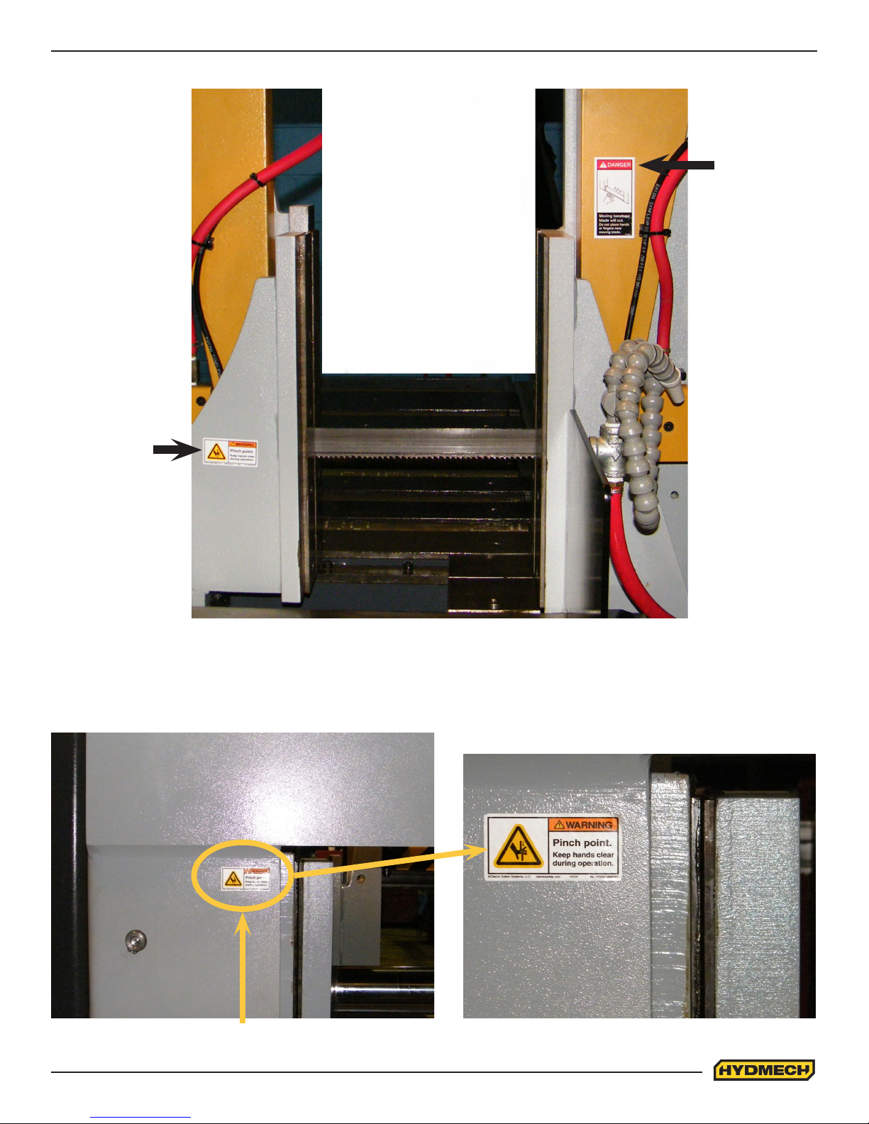
The safety hazard labels shown below are located at various positions on the machine to indicate possible safety hazards.
The location and re-order part number of all the safety labels associated with this particular model of bandsaw are indicated
at the end of this section of the manual. It is important to replace any safety hazard label that becomes damaged or illegible.
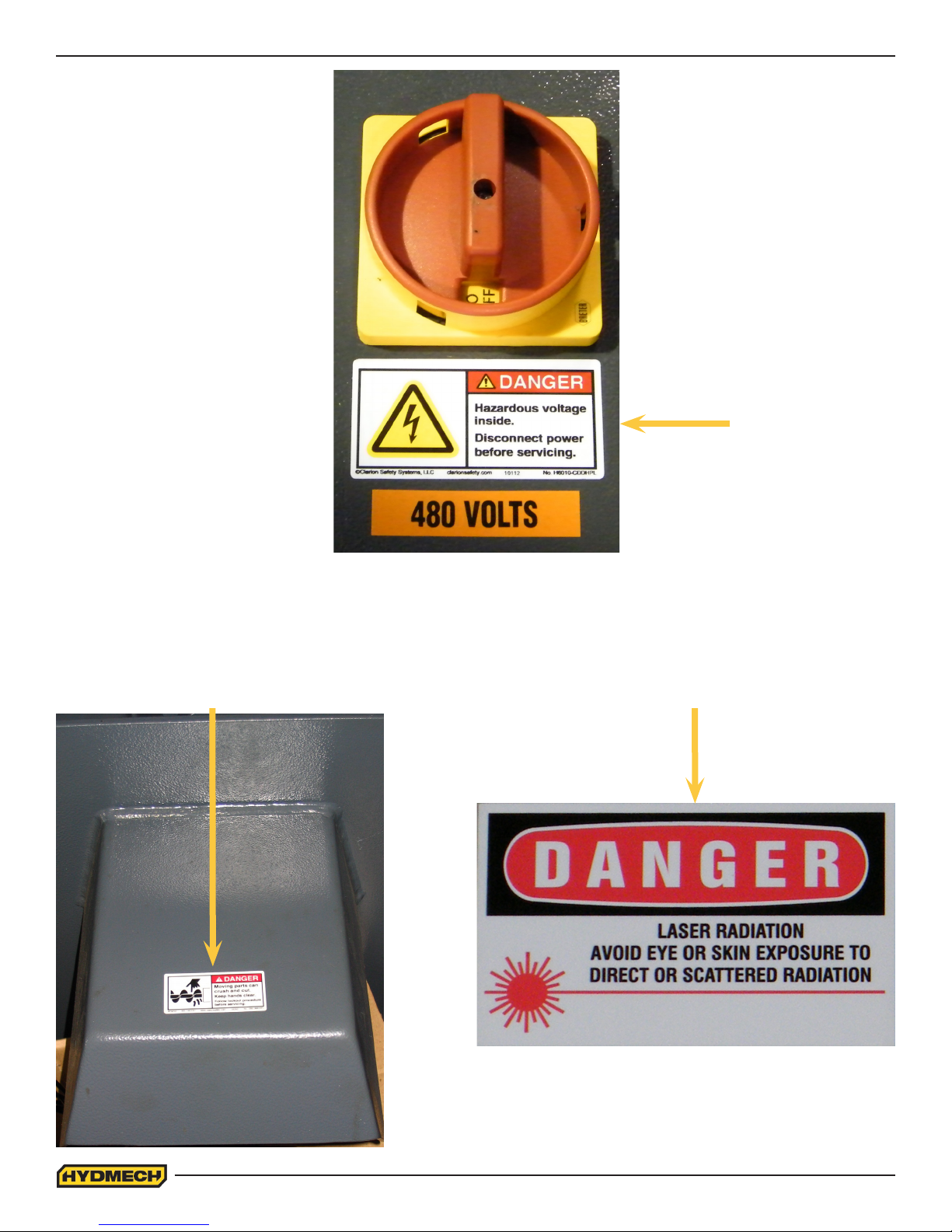
HAZARDOUS VOLTAGE INSIDE
Contact with high voltage may cause death or serious injury. Never perform
maintenance on, or near, electrical components until the machine’s electrical
power source has been disconnected. Lock-out power in accordance with your
company’s lock-out procedures before any such maintenance. The “Stop” or
“Emergency Stop” push button does not disconnect the machine’s power supply.
Hazardous voltage is still present in the machines electrical circuits.
The machine’s Electrical Disconnect Switch does disconnect voltage from the
machine’s circuits; however hazardous voltage is still present inside the main electrical cabinet, on the infeed (line) side of
the main fuses. Therefore keep hands and tools away from the infeed side of the control panel main fuses. If these fuses
need to be replaced, use a fuse puller.
Allow three minutes after locking-out power before opening any electrical enclosures. Your machine may be equipped with a
variable frequency drive that stores high voltage within its capacitors. Three minutes will allow sufcient time for this voltage
to safely discharge.
Never spray coolant directly at electrical components or cabinets.
0.6
Page 11
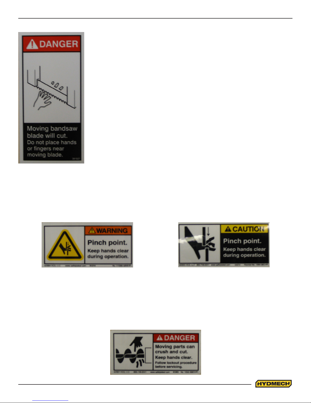
PINCH POINT
MOVING BANDSAW BLADE WILL CUT
Do NOT operate with guard removed.
Do NOT place hands or ngers near moving bandsaw blade.
For blade changing, always follow the proper Blade Changing Procedure, as given in
Section 3 of this manual.
Machine parts may move without warning, either because the machine is operating automatically, or because another
person initiates the motion. Keep hands clear of all labelled pinch points, whenever the machine is running. Machine vises
can exert great force and cause severe injury. Keep hands clear of vises and work piece when vises are opened or closed.
Be aware that vise closing or opening may result in potentially dangerous work piece movement. Be aware also that the
opening motion of a vise may create potential pinch points.
MOVING PARTS CAN CRUSH AND CUT
Keep hands clear of chip auger. Lock-out power in accordance with your company’s lock-out procedures before attempting
to clear a jam in the chip auger.
Be aware that the chip auger may start unexpectedly, either because the machine is operating automatically, or because
another person initiates the motion.
If the chip auger is stalled because of a jam, it may start without warning when the jam is cleared, unless the machine power
is locked out.
0.7
Page 12
Chip Augar
Item #: 391335
Item #: 391938
Item #: 391340
0.8
Page 13
Fixed Vise
Item #: 392801
Item #: 391397
Shuttle Vise
Item #: 392801
0.9
Page 14

Page 15

SECTION 1 - INSTALLATION
Upon delivery of your new H-18/22 SV saw, it is imperative that a thorough inspection be undertaken to check for any
damage that could have been sustained during shipping. Special attention should be paid to the electrical and hydraulic
systems to check for damaged cords, hoses and uid leaks. In the event of damage caused during shipping, contact your
carrier to le a damage claim.
SAFETY PRECAUTIONS
The machine has been designed to give years of reliable service. It is essential that operators be alerted to the safe
operation of this saw and the practices to avoid that could lead to injury. The following safety rules are at the minimum
necessary for the safe installation, operation, and maintenance of the saw. Take every precaution for the protection of
operators and maintenance personnel.
• POWER HOOK-UPS AND REPAIRS SHOULD ONLY BE ATTEMPTED BY QUALIFIED TRADESMEN.
• THE SAW SHOULD BE LOCATED IN AN AREA WITH SUFFICIENT ROOM TO SAFELY LOAD STOCK INTO
THE SAW. SECURE THE SAW TO THE FLOOR.
• THE AREA AROUND THE SAW SHOULD BE MAINTAINED IN A CLEAN AND TIDY CONDITION TO AVOID
OBSTACLES OPERATORS COULD TRIP OVER.
• THE H-18/22 SV SHOULD ONLY BE OPERATED ACCORDING TO THE SPECIFICATIONS OF THE SAW.
AVOID UNSAFE USAGE PRACTICES.
• IF AT ANY TIME THE SAW DOES NOT APPEAR TO BE OPERATING PROPERLY IT SHOULD BE
STOPPED IMMEDIATELY AND REPAIRED.
OPERATOR :
• THE SAW SHOULD NEVER BE OPERATED UNLESS ALL GUARDS AND DOORS ARE IN PLACE AND
CLOSED.
• KEEP A SAFE DISTANCE FROM ALL MOVING PARTS - ESPECIALLY THE BLADE AND VISES.
• LOOSE CLOTHING AND GLOVES SHOULD NEVER BE WORN WHILE OPERATING THE SAW. COVER LONG
HAIR.
• STOCK SHOULD NOT BE LOADED ONTO THE SAW IF THE BLADE IS RUNNING.
• LONG AND HEAVY STOCK SHOULD ALWAYS BE PROPERLY SUPPORTED IN FRONT OF AND BEHIND THE
SAW.
• NEVER ATTEMPT TO DISLODGE OR MOVE STOCK WHILE THE BLADE IS MOVING. TAKE THE TIME TO
STOP THE SAW BLADE, REMOVE OBSTRUCTIONS, AND START THE BLADE.
• MUST WEAR EYE PROTECTION.
• MAINTAIN PROPER ADJUSTMENT OF BLADE TENSION, BLADE GUIDES, AND BEARINGS
• HOLD WORKPIECE FIRMLY AGAINST TABLE.
• DO NOT REMOVE JAMMED CUTOFF PIECES UNTIL BLADE HAS STOPPED.
NO MODIFICATIONS TO THE MACHINE ARE PERMITTED WITHOUT PRIOR APPROVAL FROM
HYD-MECH. ANY APPROVED MODIFICATIONS SHOULD ONLY BE UNDERTAKEN BY TRAINED PERSONNEL.
1.1
Page 16
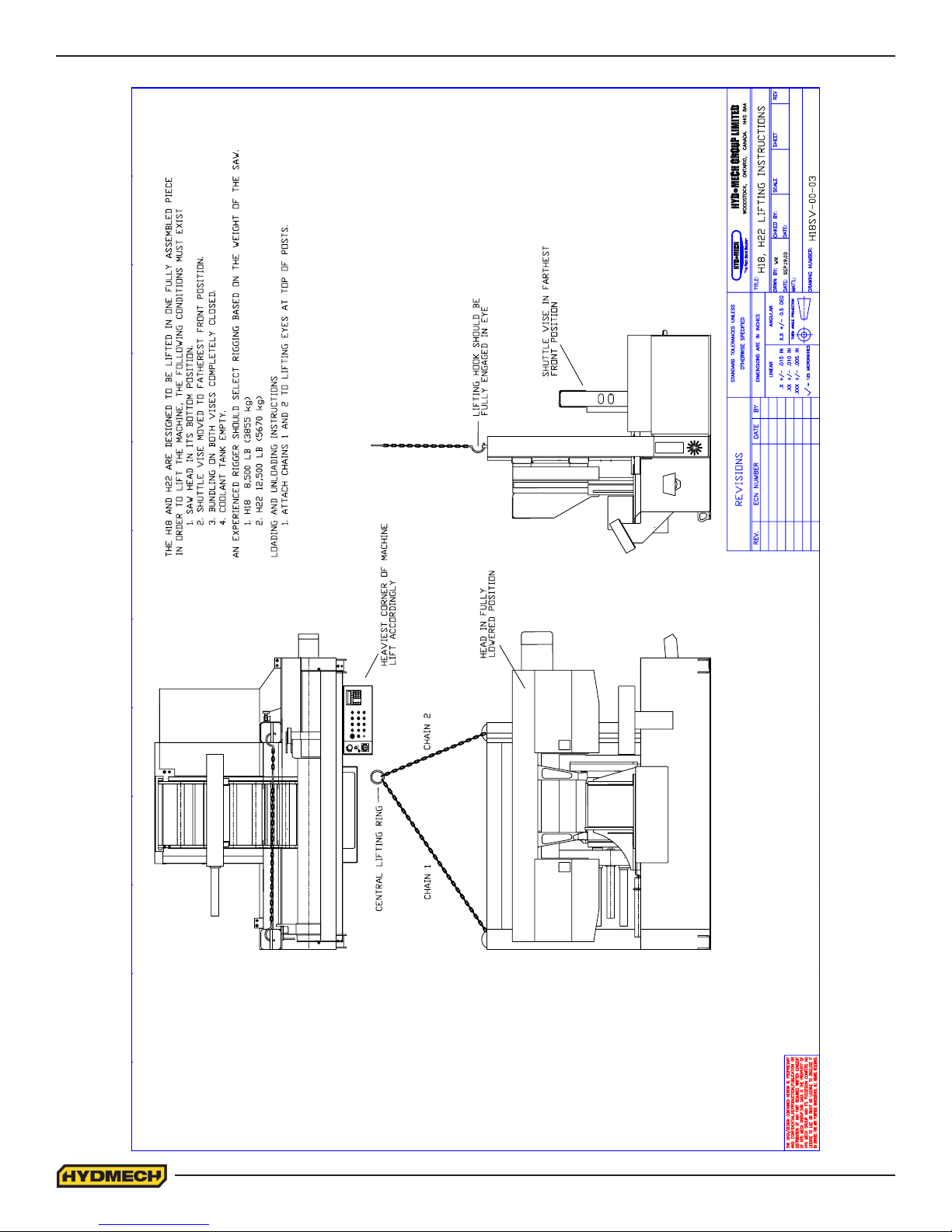
LIFTING INSTRUCTIONS
1.2
Page 17
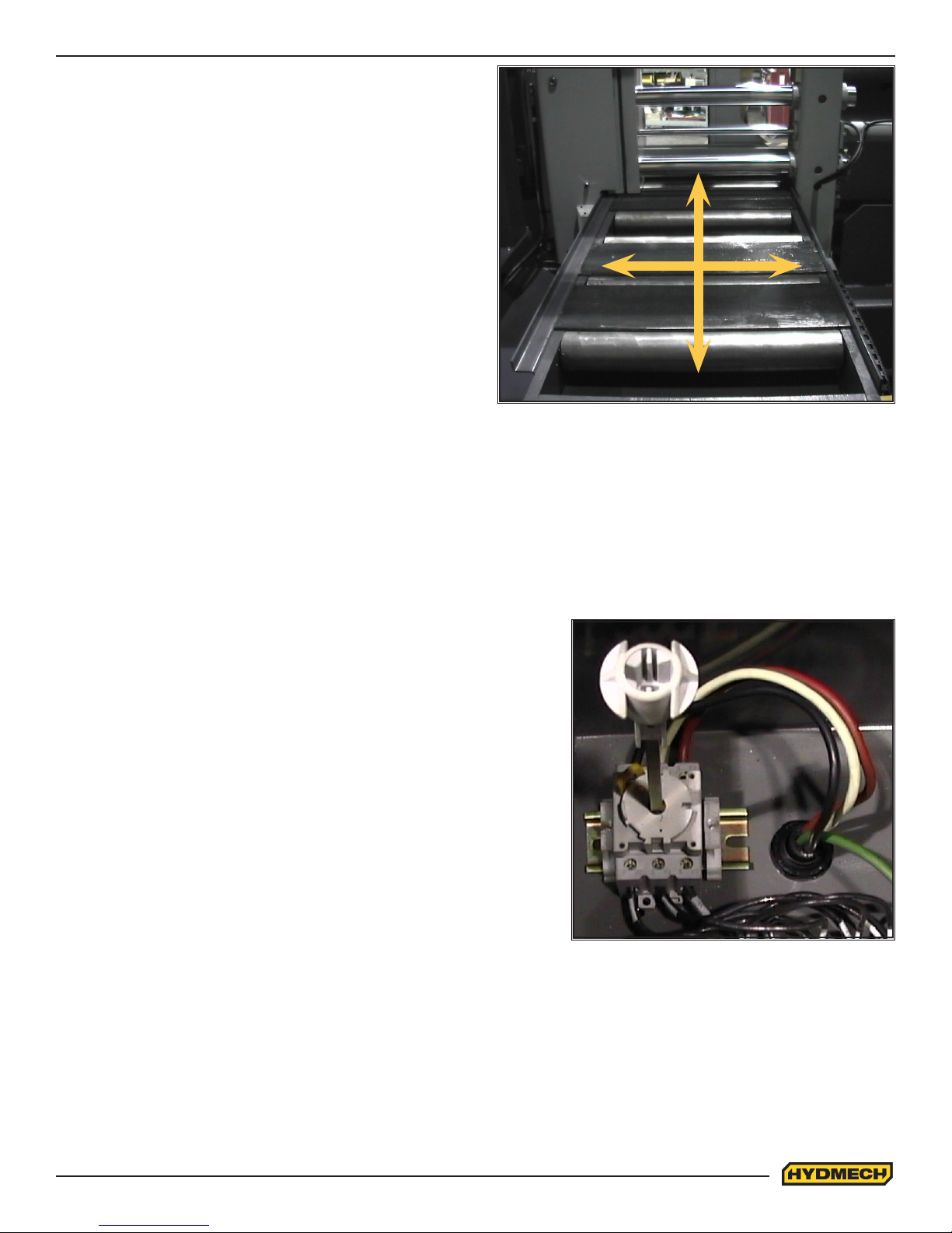
FOUNDATION, LEVELLING AND ANCHORING
The machine location should be carefully selected. A at
concrete oor area should be chosen. It should have enough
free space surrounding the machine to enable free access for
safe operation and maintenance.
Machine should be leveled in both directions i.e. along and
across its in-feed conveyor especially when machine is to be
inserted into a larger conveyor system.
Six leveling screws are provided, one in each corner of the
machine base plus one in the hydraulic cabinet. Steel plates
are to be placed under each screw to prevent their sinking
into the concrete oor. In cases where the machine is to be
anchored permanently, anchoring holes are provided. They
are located next to the leveling screws.
NOTE:
In some cases leveling the saw in-feed and auxiliary conveyor
with a slight slope towards blade is recommended. This will prevent coolant from running down the raw stock. (This is
especially true when cutting tubing or bundles).
WIRING CONNECTIONS
After the machine is leveled and anchored the necessary power hook-up needs to be performed. In order to provide safe
operation as well as to prevent potential damage to the machine, only qualied personnel should make the connections.
BEFORE START-UP THE FOLLOWING TWO POINTS SHOULD BE
CHECKED:
1. Signs of damage that may have occurred during shipping to the
electrical cables, conduits and the hydraulic hoses.
2. The hydraulic oil level is between the upper and lower lines on
the level gauge.
As supplied, the machine is set to run on three phase voltage as indicated on the serial plate and voltage label.
Power connection to the machine is made to L1, L2, L3 at the
disconnect switch and Ground terminals in the main electrical box found
beside the conveyor on the drive side. For machines equipped with a
variable frequency drive unit, an earth ground is also recommended.
During the initial hook-up it is very important to check that the phase order is correct. This is indicated by the hydraulic pressure gauge registering a pressure rise and the blade running in a counter clockwise direction. If the hydraulics do not register an immediate pressure rise, shut
the hydraulics off and change the phase order.
ATTENTION: Running the hydraulics “backwards” can damage the hydraulic pump.
1.3
Page 18

EARTH GROUNDING PROCEDURE
1. The customer is to provide and install a ground rod approximately .60 (15mm) diameter, copper clad steel, to be
driven no less than 8’ (2.5m) into the ground, no more than 10’ (3m) away from control enclosure.
2. The ground rod is to be connected to customer’s in plant ground system. This connection shall be made directly
at the ground rod. (If applicable).
3. It is desirable that the overall resistance to ground measured at the ground rod does not exceed 3 ohms.
Customer is advised to consult local power company for further information on grounding.
4. The ground rod is to be connected to the ground terminal in the control enclosure using insulated, stranded
copper wire. The wire gauge size is to be determined according to the electrical code of the customer’s local
electrical authority.
5. An additional point to check is to ensure continuity of all ground within the control enclosure. Start with the main
power entrance ground terminal where the internal ground conductors should originate and then connect to, the
DIN terminal strip, control transformer, and the lid of control enclosure. Also, the PLC and Interface units should
have their own ground conductors connected to one of the main ground terminals.
6. A properly functioning ground system will:
- provide safety for personnel.
- ensure correct operation of electrical/electronic apparatus.
- prevent damage to electrical/electronic apparatus.
- help dissipate lightning strikes.
- divert stray radio frequency (RF) energy from electronic/control equipment.
HYDRAULIC OIL AND CUTTING FLUID
The H-18/22 SV bandsaw is supplied with Texaco Rando HD46 hydraulic oil. If it is necessary to change the oil to a
different brand see the HYDRAULIC SECTION for equivalent grade oil.
No cutting uid is supplied with the machine. There are two types of coolant available:
• Oil based; dilute 1:10 ratio (one part concentrated coolant to 10 parts water)
• Synthetic; dilute as recommended by the manufacturer.
1.4
Page 19

SECTION 2 - OPERATING INSTRUCTIONS
This section has been prepared to give the operator the ability to set up the saw for most cutting situations. Before cutting
any material, the operator should be familiar with all operations and controls as well as the basic cutting theory described
below. The saw is equipped with variable blade speed and hydraulic feed control, as well as an extensive door chart to
guide the operator to the correct setting of these controls.
BLADE BASICS
Technology is rapidly changing all aspects of production machining. Metal cutoff is no exception. The advances made
in the bandsaw blade industry have denitely brought down the cost per cut, despite the three fold higher price of high
technology blades. Variable pitch, bi-metal blades (like the 4/6 or 3/4 bi-metal blade supplied with the machine) last much
longer, cut faster, and more accurately than conventional carbon steel blades. In order to take advantage of the superiority
of bi-metal blades, it is critical to properly “break-in” a new blade. This is accomplished by taking two or three cuts through
solid four or ve inch diameter mild steel at an extremely slow feed rate. (It is also advisable to utilize a slow blade speed)
These two or three slow cuts sufciently lap (polish) the teeth on the new blade so that it does not snag the material being
cut. Proper break-in will alleviate blade vibration; improve surface nish, accuracy, and blade life.
After “break-in”, the following six points must be closely monitored to ensure long blade life:
1. Proper blade tension should be maintained. (See Section 3, Maintenance and Troubleshooting)
2. Generous coolant application is essential with most materials. A high quality and well mixed coolant will extend
blade life, and also increase cutting rate and quality. On those materials where coolant is undesirable for cutting,
a slight coolant ow or periodic oiling of the blade is necessary to prevent the blade from being scored by the
carbide guides.
3. The stock being cut must be securely clamped in the vises.
4. The proper feed force should be chosen. (see Saw Cutting Parameters: Step 2)
5. The proper blade speed must be selected. (see Saw Cutting parameters: Step 4)
6. The proper feed rate must be applied. (see Saw Cutting Parameters: Step 5)
VARIABLE SPEED CONTROL
Blade speed can be adjusted for the H18 innitely between 50 to 350 SFM(Surface Feet/Minute) (15 to 107m/min) and
for the H22, 40 to 300 SFM(Surface Feet/Minute) (12 to 92m/min). Adjustment should be made only when the blade is
running. Clockwise rotation of the knob increases blade speed while counter clockwise rotation decreases blade speed.
THE CONTROL PANEL
START-UP
The control console has been designed to simplify the operation of the saw, to give the operator the ability to stop any
function at any time, and to be able to control all the functions remotely. We cannot overstress the importance of
familiarizing yourself with the controls prior to star ting the machine.
NOTE:
1. ALL SWITCHES MUST BE IN THE CENTER NEUTRAL POSITION TO START THE MACHINE!
2. WHEN STARTING THE MACHINE FOR THE FIRST TIME MAKE SURE THAT BLADE IS MOVING IN A
COUNTERCLOCKWISE DIRECTION, AND THAT THE HYDRAULIC PRESSURE IS 1000 PSI (6890kP). IF
THERE IS NO IMMEDIATE PRESSURE, SHUT THE SAW DOWN AND CHANGE THE PHASE ORDER.
MANUAL OPERATION
Manual Operations can be performed when the PLC 100 controller is set to MAN (AUTO is active when a RED light is on
above the AUTO/MAN button). All functions are self-explanatory. Specic control button functions are described on the
following pages.
2.1
Page 20
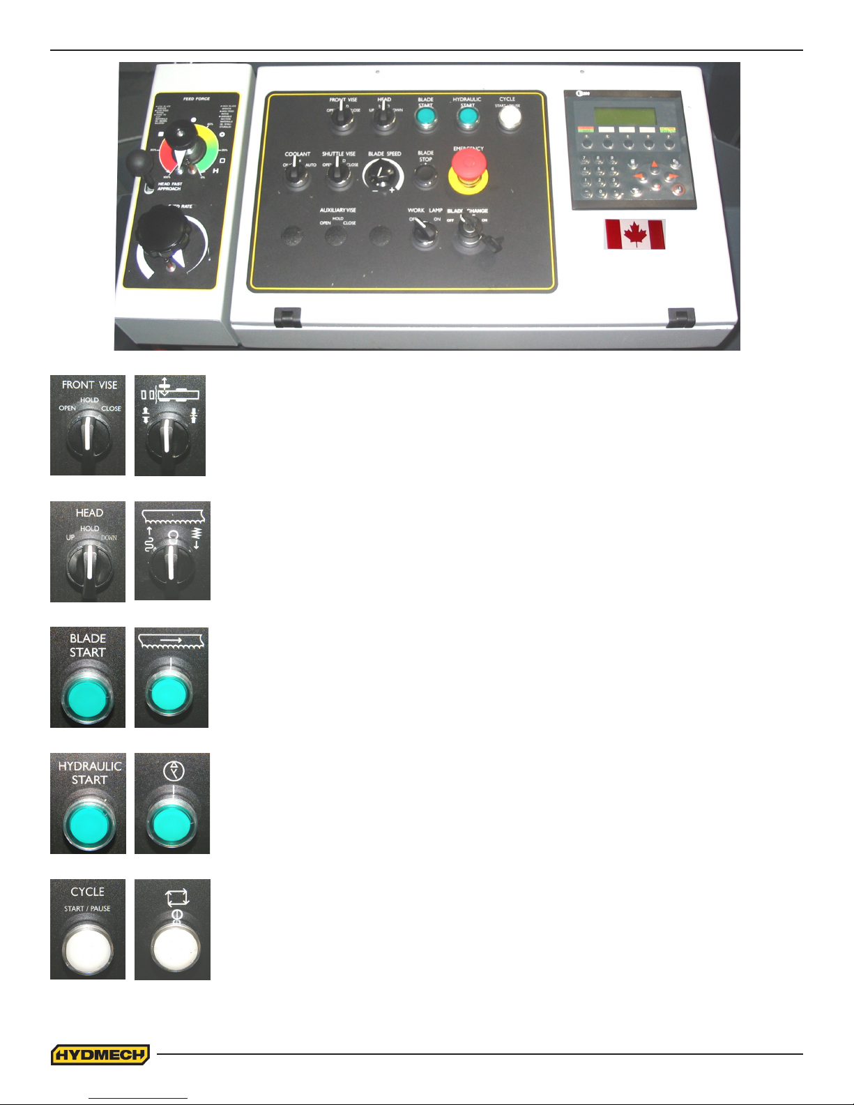
FRONT VISE
This switch has three positions, OPEN, HOLD and CLOSE. With the switch held in the
OPEN position the vise will open all the way or until the switch is released. With the switch in
the HOLD position, the vise will stay where it is and will not move freely
although it will not resist a large force indenitely without creeping. In CLOSE, the vise will
close all the way, or until it encounters enough resistance to stop it.
HEAD CONTROL
This switch has three positions: UP, HOLD and DOWN. The switch is inactive unless the
PLC is in manual mode. In the UP position, the head will rise until it trips the head up limit,
which is adjustable. In the HOLD position the head will stay still. In the DOWN position the
head will descend until it reaches the bottom of the stroke. The speed of descent is
controlled by the Head Feed and Head Force Limit controls.
BLADE START
The blade can be started only when the hydraulics are running in either manual or auto
mode.
NOTE: In automatic Mode the head will not descend until the blade has been started, which
the PLC will prompt the operator to do so.
HYDRAULIC START
To start the hydraulic system, the switches for the head and both vises must be in the
“NEUTRAL” position. The “HYDRAULIC START” button must be depressed and held in
momentarily until the PLC display becomes active.
CYCLE START / PAUSE
This button starts the cutting cycle and will stay illuminated until the cycle is completed. The
PLC control system will prompt you to start the blade if it is not running. The
machine will then begin the automatic cycle until completed when it will shut itself off. The
current cycle can be PAUSED by pressing this button at any time during a cycle and
restarted by pressing it again.
2.2
Page 21
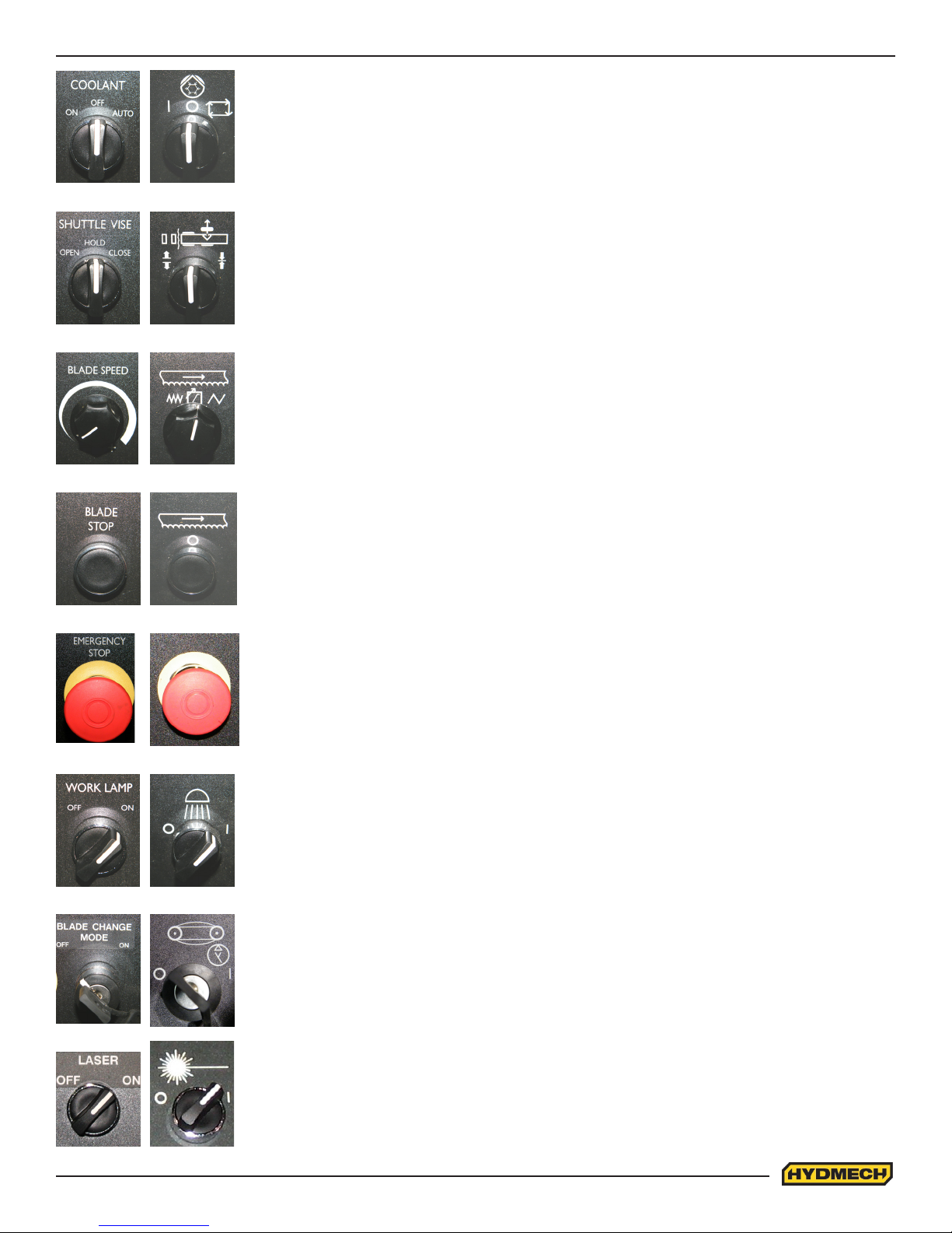
COOLANT
This switch has three positions, AUTO, OFF, and ON. In the ON position, the coolant system
will operate when there is power to the machine; this allows using the wash gun to clean
the machine. In the OFF position, the coolant system is inactive. In the AUTO position the
coolant system will only run when the blade is on. The coolant system can also be run only
when both the blade is on and the head is descending by selecting this option in the PLC
parameters.
SHUTTLE VISE
This switch has three positions, OPEN, HOLD and CLOSE. With the switch held in the
OPEN position the vise will open all the way or until the switch is released. With the switch
in the HOLD position, the vise will stay where it is and will not move freely although it will not
resist a large force indenitely without creeping. In CLOSE, the vise will close all the way, or
until it encounters enough resistance to stop it.
BLADE SPEED
H18, 50 to 350 SFM(Surface Feet/Minute) (15 to 107m/min)
H22, 40 to 300 SFM(Surface Feet/Minute) (12 to 92m/min)
Adjustment should be made only when the blade is running. Clockwise rotation of the knob
increases blade speed while counter clockwise rotation decreases blade speed.
BLADE STOP
Stops the blade. If the blade is stopped during a cycle, the cycle will continue but will not let
the head descend until the blade is started.
EMERGENCY STOP
This mushroom button stops the blade and hydraulic motors. Both vises will hold their
position but, pressure will begin to fall off. Long pieces of work should always be supported
so they will not become loose over time and fall while the machine is shut down. This is a
latched button and must be pulled out to start the machine.
WORK LAMP
This switch has two positions, OFF and ON.
BLADE CHANGE MODE
This lock is provided for the safety of the operator during the blade changing procedure.
When the lock is in the “ON” (I) position, the door interlocks are disabled and the only functions that are active are the HEAD and BLADE TENSION controls. All other controls are
inactive. After the blade has been changed the lock must be switched to “OFF” (O) in order
to operate the machine.
LASER (OPTION)
This switch has two positions, OFF and ON.
2.3
Page 22
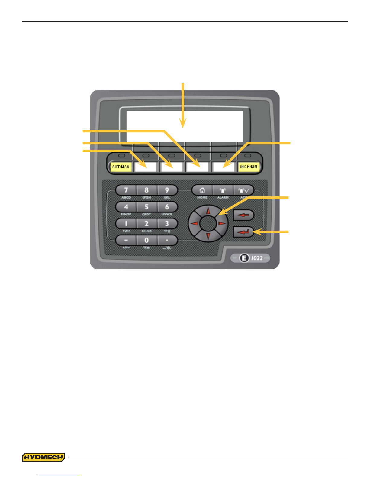
PLC 100 CONTROL SYSTEMS
NOTE: This instruction manual is applicable to the H-18/22 SV equipped with a MITSUBISHI PLC.
OPERATION OVERVIEW
DISPLAY WINDOW
F4
F3
F5
F2
NAVIGATION
KEYS
ENTER KEY
The PLC is a programmable logic controller which allows the operator to run the machine in both manual and automatic
modes.
In manual mode, all functions can be operated by using a combination of selector switches on the control console and
the PLC function buttons. Also the operator has the ability to execute a single cut utilizing a preprogrammed “Single Part
Cycle”.
In automatic mode, the PLC has the capacity to program and store 99 jobs. Designated job numbers can be programmed
for quantity required (maximum of 999 pieces) and lengths from 0.1” to 220” (5588mm).
Jobs can be run individually or in a QUEUE which allows a maximum of 5 jobs to run consecutively and the queue can be
repeated automatically as well up to 99 times.
All machine operators should be familiar with the entire operation instructions prior to operating the machine.
NOTE: If an emergency situation arises during any operation, use the large red mushroom “STOP” button located on the
control panel to shut down the machine. To operate the machine, the “STOP” button must be pulled out.
2.4
Page 23
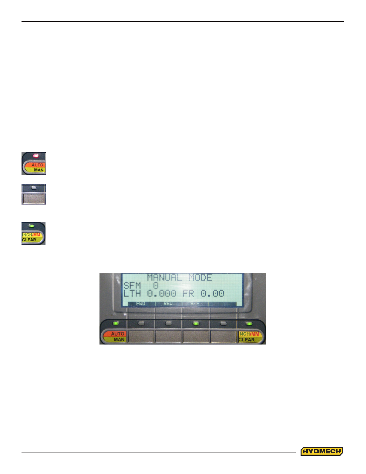
ACTIVATING THE PLC
Position the head, xed vise, and shuttle vise switches to the NEUTRAL (center) positions. If any of these switches are
not in the NEUTRAL position, the hydraulics will not start. The PLC control will become active when the HYDRAULIC
START button is depressed and “held in” momentarily. First, the HMI and PLC’s current revision number will be shown on
the display window and nally the MANUAL MODE display window will appear as shown below. The AUTO/MAN green
indicator light will be on and all MANUAL controls are enabled. The “LTH” value (shuttle vise position) will always display
zero at start up. The “LTH” value can be reset or cleared at any time in MANUAL mode by pressing the CLEAR function
button.
FUNCTION KEY DESCRIPTIONS
If a red indicator light above a function button is illuminated, it means that the function printed in red is enabled. If a green
indicator light above a function button is illuminated, it means that the function printed in green is enabled.
The following are the function keys for AUTO and MAN modes:
AUTO / MAN MODE
- This key will toggle between MAN and AUTO modes. Auto mode cannot be accessed unless the front vise is
closed.
- Also used to stop an automatic job in progress by switching to MANUAL mode.
UNLABELLED
- The function of these keys are displayed directly above them. The function will change as the PLC is
switched from one mode to another and as the process of each mode is changed.
INCH/MM
- While depressed momentarily, it resets the displayed length value to zero. If held depressed for a few
seconds, the displayed length will toggle between millimeters and inches and the blade speed in either surface
feet per minute or meters per minute. It becomes disabled once any cycle is initiated.
MANUAL MODE FUNCTION KEY DESCRIPTIONS
While in manual mode, the display will show the current function of the unlabelled key. They are shown below.
FWD: FORWARD - This key will advance the shuttle vise toward the head (home position). If pressed simultaneously with
the REV key, (the front vise must be closed and a password is required) the parameters will be displayed.
REV: REVERSE - This key will retract the shuttle vise away from the head (home position). If pressed simultaneously with
the FWD key, (the front vise must be closed and a password is required) the parameters will be displayed.
S/F : SLOW / FAST - This key will toggle between slow and fast shuttle speed.
2.5
Page 24
SINGLE PART CYCLE OPERATION
In MAN mode, the PLC allows the operator to initiate a “Single Part Cycle” to cut one piece at a desired length. To
accomplish this, follow the procedure below.
1. A trim cut should be made before initiating the “Single Part Cycle” operation.
2. Make sure the front vise switch is in the closed position and set the head up limit switch. The AUTO/MAN indicator
light will ash alternately green and red.
3. Make sure the head is set so that the blade is above the material and the head selector switch is in the HOLD
position.
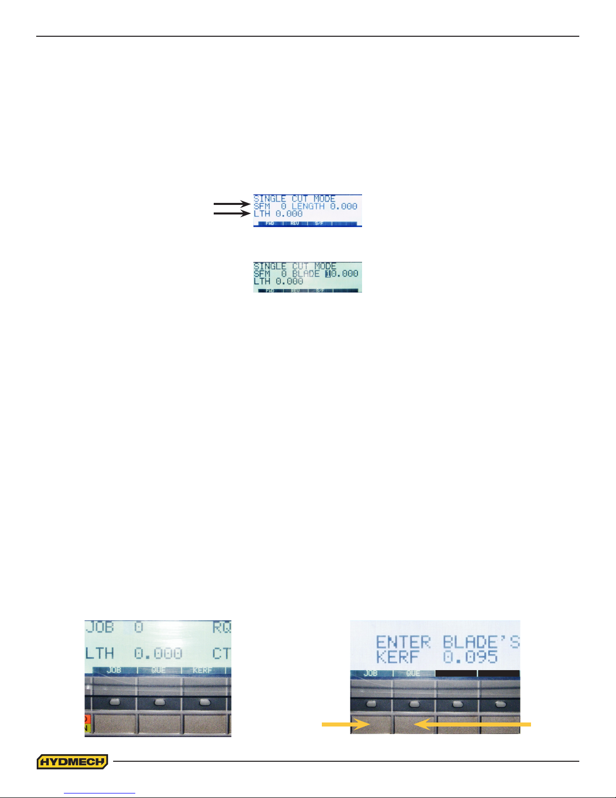
4. The cursor will be ashing at the LENGTH position. Key in the desired value from 0” to 220” and press enter. If the
value is incorrect, re-enter the value and press enter again.
BLADE SPEED
LENGTH
5. If the blade is not running, you will be prompted by the word “BLADE” ashing on the display window. Start the
blade and adjust the blade speed as required.
6. When the blade is started, the word “BLADE” will change to the word “CYCLE” ashing on the display window.
Press CYCLE START and the cycle will begin.
7. When the cycle button is pressed, the shuttle vise will move forward to the home position before executing the
length movement. The head will descend and make the cut.
8. When the cut is completed, the head will rise to the head up limit switch, the blade will stop and the display
window will reset for the next cut.
9. To cut another piece, repeat steps 2 through 6.
NOTES:
1. To “PAUSE” the “SINGLE CUT CYCLE”, press the “CYCLE START” button. The “CYCLE START” button will
begin to ash and the screen will indicate a paused condition. All movements will immediately cease. To continue
the cycle, press the “CYCLE START” button again.
2. To cut multiple pieces, switch to AUTO MODE and follow the automatic procedures.
KERF CORRECTION
When making cuts, the PLC must account for an amount called the “KERF,” which is the material removed by the blade.
This value must be entered into the PLC and must be checked and adjusted as required when the blade has been
replaced. This is due to the fact that there is a variance in the kerf value from blade to blade. The original value entered
is for the blade installed at the time of manufacture. If the kerf value is to be adjusted, its value can be accessed while in
Auto Mode. Press and hold the key below the word “KERF” on the display until the display appears as shown. Enter the
desired kerf value and press enter.
NOTE: Whenever a new job or new material is being loaded for production, the head up limit switch should be properly
set to clear the material, positioned for a trim cut and the front vise closed (in “MANUAL MODE”).
RETURNS TO
AUTO MODE
2.6
RETURNS
TO THE
QUEUE
Page 25
AUTOMATIC OPERATION
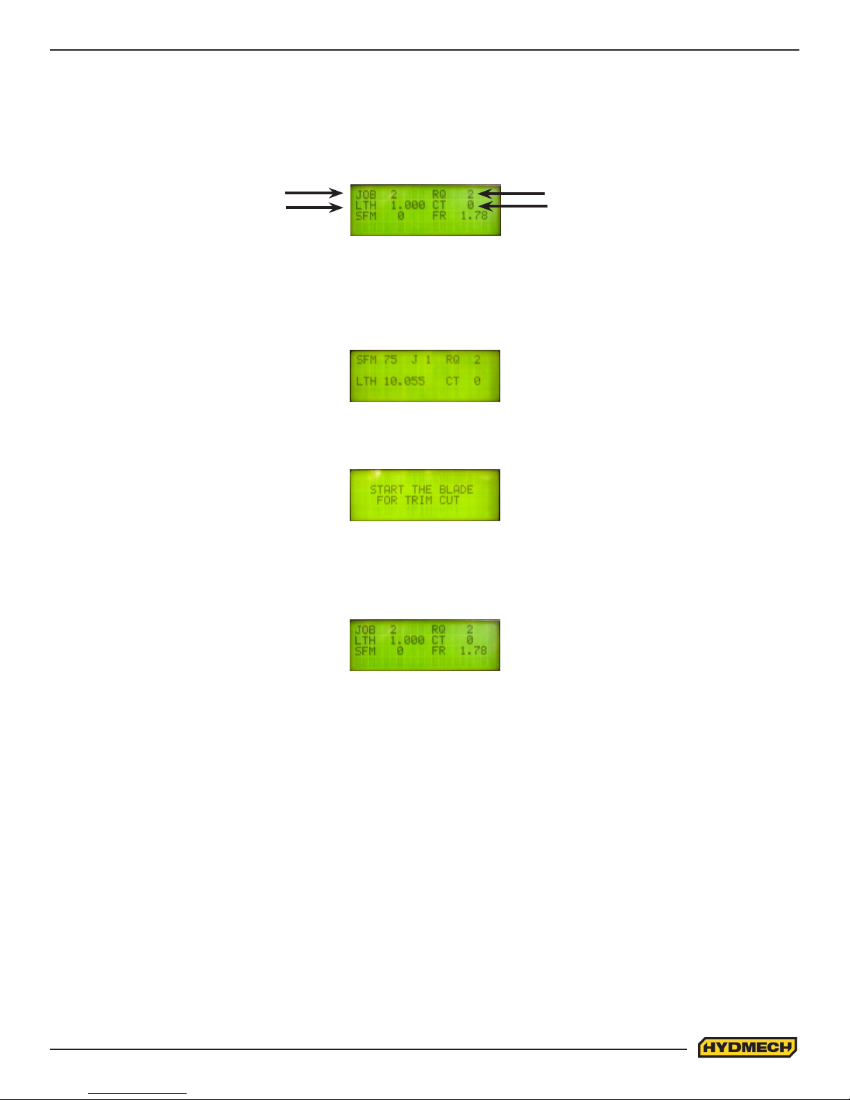
When the AUTO/MAN button is pressed, the red indicator light above it will come on, and the blade will stop if it has been
running. The screen will change to the JOB display window as shown below and be ready for editing or starting a new job.
All manual functions will be disabled.
JOB DISPLAY WINDOW
JOB NUMBER
LENGTH
REQUIRED QTY
CUT QTY
PROCEDURE FOR EDITING OR STARTING A NEW JOB IN AUTO MODE
1. In AUTO mode, key in a job number from 0 to 99 and press enter. The REQUIRED QUANTITY (RQ), LENGTH
(LTH) and QUANTITY CUT (CT) will be displayed. The values displayed can be edited by pressing ENTER after
each new value, and the job will be stored in memory with the new values. To navigate through the values, use
the CURSOR keys.
2. After the values are entered, press the CYCLE START button. The switch will illuminate and the display window
will prompt you to start the blade for a trim cut (if the “Trim Cut” parameter has been selected).
CAUTION:
If the head is in its down position, it will rise to the head up limit so that no damage to the blade will occur.
3. After starting the blade, the head will descend for the cut and the machine will complete the required job.
4. At the completion of the job, the machine will shut down if “0” has been entered in the “POWER DWN TIMER”
parameter or continue running for the specied time up to a maximum of 180 minutes.
NOTES:
1. The “CT” value is the accumulated total number of parts that have been cut from the JOB number since it was
last reset. The machine will only cut the quantity that is the difference between REQUIRED QUANTITY and CUT
QUANTITY. When REQUIRED QUANTITY equals CUT QUANTITY, the machine AUTO CYCLE will stop and you
will be unable to restart the same job until the “CUT QUANTITY” value has been reset.
2. The AUTO cycle may be exited and stopped at any time by pressing the AUTO/MAN key.
NOTE: Before entering “AUTO MODE” and working with a “QUEUE”, follow the same procedures outlined on the previous
page for “SINGLE PART CYCLE OPERATION” with regards to setting up for an initial trim cut.
2.7
Page 26
WORKING WITH A QUEUE
The purpose of a QUEUE is to allow the operator to run several jobs (max of 5) in series if they are of the same material
and shape.
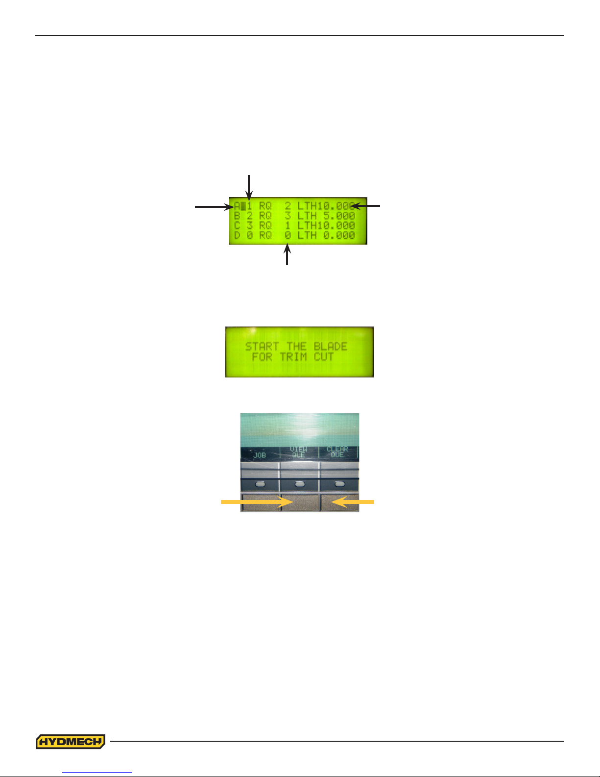
In AUTO mode, press the key below the word “QUE” on the display and the display window will appear as shown.
If you choose to VIEW the QUEUE, press the key below the words “VIEW QUE” on the display. The display window will
show the jobs in the current QUEUE. Four jobs at a time are shown.
PROGRAMMED JOB
NUMBER
FIRST JOB
LENGTH TO CUT
QUANITY TO CUT
Use the CURSOR buttons to view all the jobs. To run the QUEUE as it is displayed (jobs may be edited in this mode),
press the CYCLE START button on the control panel. The screen will now prompt you to start the blade for a trim cut.
If you choose to edit the QUEUE, press the key below the words “CLEAR QUE” on the display. This will clear any jobs
that are in the QUEUE and the display window will show an empty Queue. Jobs may be entered and edited in this mode.
VIEW QUE CLEAR QUE
To ll the QUEUE, follow these two steps.
1. Key in a job number and press ENTER. If that job number has previously been programmed, its values will be
displayed. The cursor will move to the next position in the QUEUE. Up to ve jobs may be in the QUEUE at any
time. The job values can be edited in this mode.
2. When the desired jobs have been entered, you may press the CYCLE START button on the control panel to
execute the jobs in the QUEUE.
(Follow the same procedures to initiate a cycle as in “AUTOMATIC OPERATION”)
The QUEUE may be exited to the previous screen at any time by pressing the key under JOB. At completion of the
“QUEUE,” the machine will shut down if “0” has been entered in the “POWER DWN TIMER” parameter or continue
running for the specied time up to a maximum of 180 minutes.
2.8
Page 27
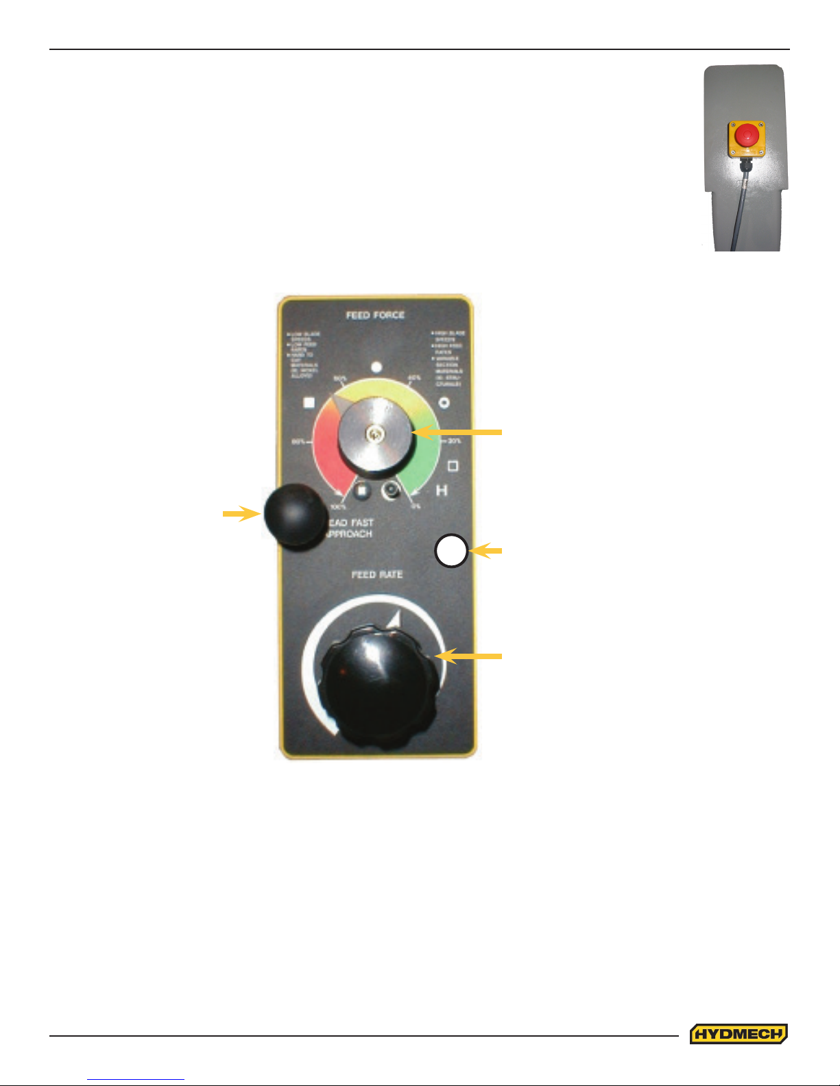
SHUTTLE EMERGENCY STOP
A second emergency stop push button is mounted to the shuttle above the shuttle vise cylinders. This
mushroom button stops the blade and hydraulic motors. Both vises will hold their position but, pressure will
begin to fall off. Long pieces of work should always be supported so they will not become loose over time
and fall while the machine is shut down. This is a latched button and must be pulled out to start the machine.
HYDRAULIC FEED CONTROL
The Hydraulic Feed Control is located to the left of the control panel. These controls allow independent
control of
Feed Force (FF) and Feed Rate (FR)
FEED FORCE KNOB
Used to set feed force limit (counterclockwise
rotation to increase and clockwise rotation to
decrease).
FF IS NOT APPLICABLE TO H40 MODEL
FAST APPROACH LEVER.
Depress for fast head
descent
EXTRA FINE METERING VALVE
Used to set feed rate (counterclockwise
rotation to increase and clockwise rotation to
decrease).
FEED RATE KNOB (Fine Metering)
Used to set feed rate (counterclockwise
rotation to increase and clockwise rotation to
decrease).
The FINE METERING DDF VALVE is equipped with two Feed Control Knobs. Extra ne Micrometer style Knob and Fine
Metering Knob. The main difference between both Feed Controls is that the Extra Fine Metering valve does not work with
the Feed Force Limit Valve. It is recommended to use only one feed control at a time with the second control valve shut.
The choice of control is arbitrary and a matter of trial.
In some cases Extra ne Metering provides better results in others Fine Metering Control.
As a rule of thumb:
Extra Fine metering valve should be used
• if required feed is in a range of .12-.25”/min
• and/ or when cutting hard material
• or when work hardening may occur.
Fine metering valve should be used
• When cutting structural steel
• and/ or bundles
• High feed rates required
2.9
Page 28
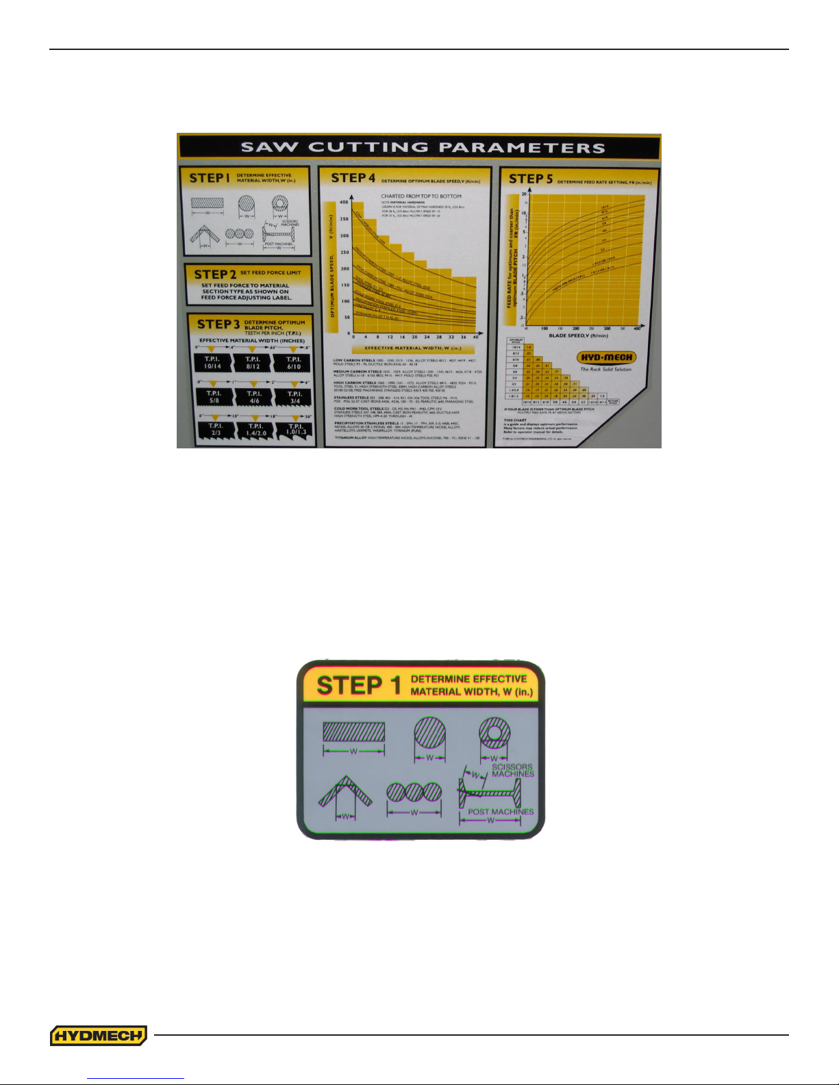
CUTTING PARAMETERS CHART
A full size CUTTING PARAMETERS CHART is mounted on the front of the saw. The chart contains ve steps for the
operator to follow in order to achieve optimum performance of the saw. These steps are detailed on the following pages.
Saw Cutting Parameters Chart
CHART EXAMPLE #1
We will use the parameters chart to set up the saw for cutting 8” (200mm) Diameter #1045 Carbon Steel.
STEP 1: DETERMINE EFFECTIVE MATERIAL WIDTH - W (inches) or (mm)
Effective material width, W (in.) for most common shapes of materials, is the widest solid part of the material to be in
contact with blade during cutting. For simple shapes, as illustrated on the chart, this can be directly measured. For
bundles of tubes and structurals, measuring the effective width is difcult. Effective width is 60% to 75% of the actual
material width.
Material Width Chart
NOTES:
1. Effective material width, as determined here in STEP 1, can be thought of as the average width of material “seen”
by each tooth, and it is used in STEPS 3 and 4.
In Example #1, for an 8” (200 mm) diameter solid, Effective Material Width is 8” (200mm).
2.10
Page 29
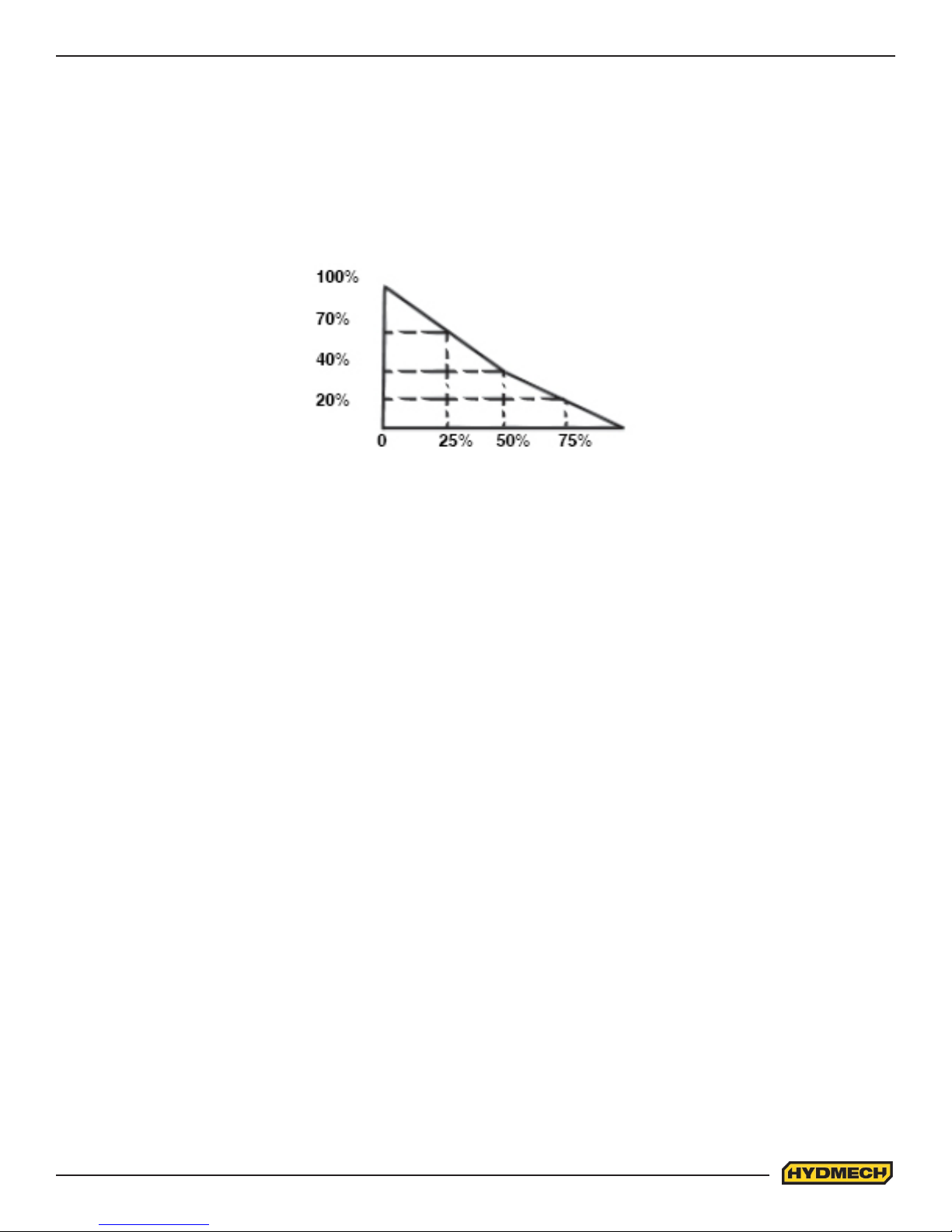
STEP 2: SET FEED FORCE LIMIT
The Feed Force Limit is the maximum amount of force with which the head is allowed to push the blade into the
work-piece.
CUTTING SOLIDS
For cutting solids, the wider the section, the less FF should be set, to avoid blade overloading. See the graph below.
% OF FF
SETTING
(INDICATED
ON LABEL)
MAT’L WIDTH AS %
OF SAW CAPACITY
EXAMPLE: When cutting a solid which is 1/2 of machine capacity using the graph, locate 50% on the horizontal line and
travel upwards to the plotted line and then travel directly across to the vertical FF Setting line. The point that you have
arrived at shows a setting of 40% for a piece 50% of capacity.
CUTTING STRUCTURALS: A reduced Feed Force Setting is used when cutting structurals.
2.11
Page 30
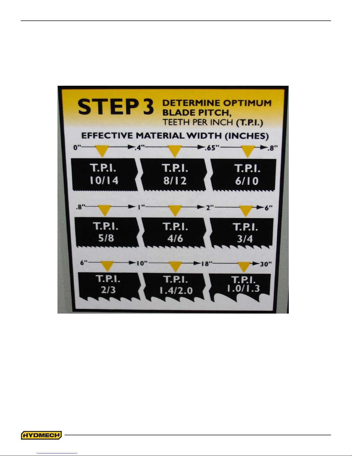
STEP 3: DETERMINE OPTIMUM BLADE PITCH - TEETH PER INCH (T.P.I.)
Selecting a blade with proper tooth pitch is important in order to achieve optimal cutting rates and good blade life.
For cutting narrow or thin wall structural materials a ne blade with many teeth per inch (T.P.I.) is recommended. For wide
materials a blade with a coarse pitch should be used. The sketch can be referenced for the blade pitch changes for
differing effective material widths.
Optimum Blade Pitch (T.P.I) for Material Width (Inches)
It is impractical to change the blade to the proper pitch every time a different width of material is cut and it is not
necessary, but remember that the optimum blade will cut most efciently. Too ne a blade must be fed slower on wide
material because the small gullets between the teeth will get packed with chips before they get across and out of the cut.
Too coarse a blade must be fed slower because it has fewer teeth cutting and there is a limit to the depth of a cut taken by
each tooth. Allowance for the use of a non-optimum blade is made in STEP 5.
Example #1: Effective material width of 8” (200 mm):
Optimum blade has 2/3 teeth per inch.
2.12
Page 31
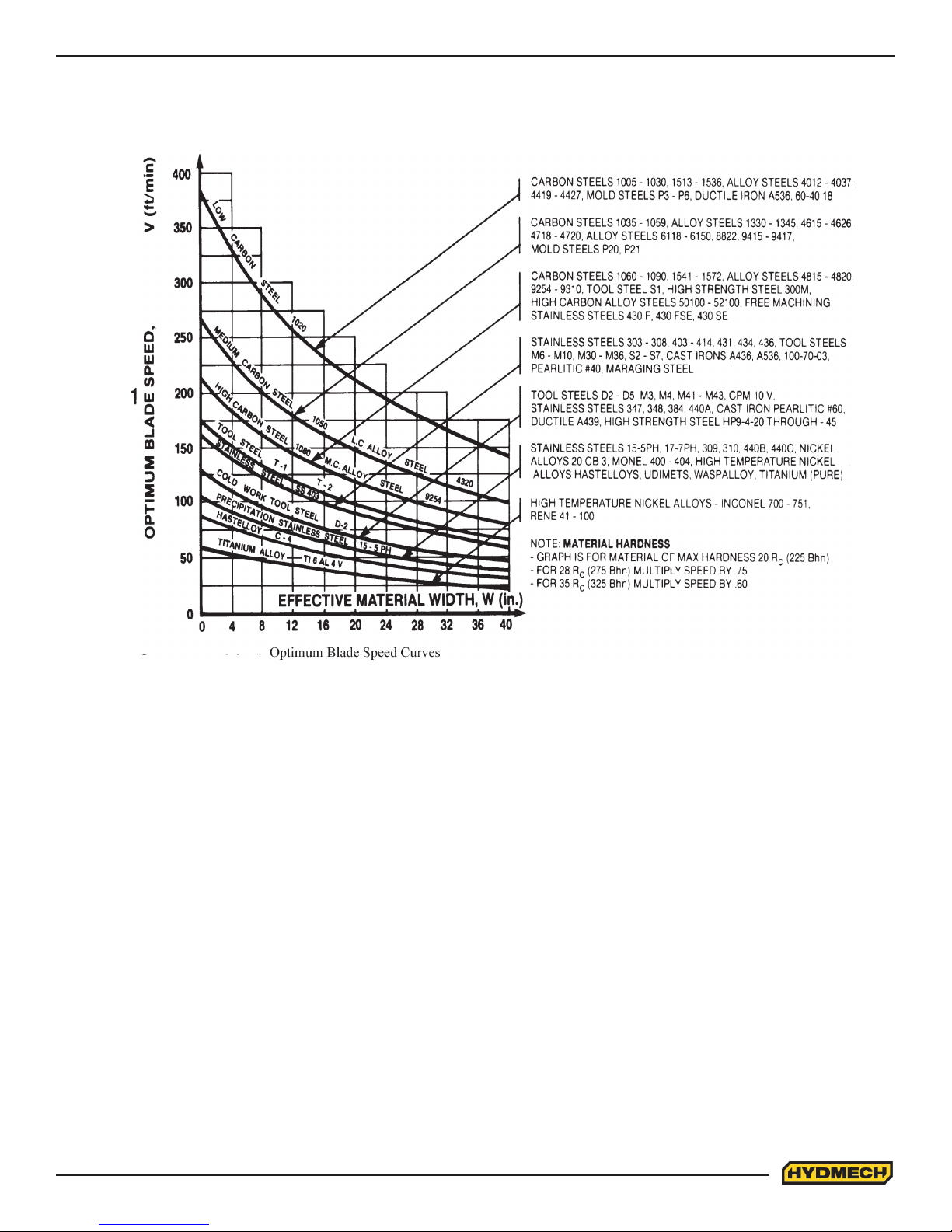
STEP 4: DETERMINE OPTIMUM BLADE SPEED, V (ft/min) (m/min)
The relationship between optimum blade speed and effective material width for various materials is represented on the
graph shown.
The graph shows that as effective material width gets wider or as material gets harder, lower blade speeds are recommended. If material is narrow or soft, higher blades speeds should be selected.
Example #1
1. 8” (200mm) diameter #1045 Medium Carbon Steel solid bar is to be cut.
2. On the graph above nd the Medium Carbon Steel Curve which represents the optimum blade speeds for 1045
Carbon Steel.
3. On the horizontal axis (effective material width axis) nd number 8 which represents effective material width of an
8” (200mm) diameter solid.
4. Find the point where a vertical line from 8” (200mm) intersects the Medium Carbon Steel Curve.
5. From this intersection point run horizontally left to the vertical axis (optimum blade speed axis) and nd the point
marked “200”.
6. For 8” (200mm) diameter, 1045 Carbon Steel solid bar 200 ft/min (60m/min) is the optimum blade speed.
NOTE:
1. Higher than optimum blade speed will cause rapid blade dulling. Lower than optimum blade speeds reduce
cutting rates proportionately and do not result in signicantly longer blade life except where there is a vibration
problem. If the blade vibrates appreciably at optimum speed as most often occurs with structurals and bundles, a
lower blade speed may reduce vibration and prevent premature blade failure.
2. Material Hardness - The graph above illustrates blade speed curves for materials of hardness 20 RC (225 Bhn) or
lower. If the material is hardened then the multipliers need to be used. These multipliers are given in the NOTE at
the bottom right of the graph. As the hardness increases the optimum blade speed decreases.
2.13
Page 32
The following table gives examples of the optimum blade speeds for different materials.
# MATERIALS OPTIMUM BLADE SPEED
(ft/min) (m/min)
1 5” (125mm) Diameter Solid Carbon Steel 225 70
2 12” (300mm) I-Beam 290 90
3 4” x 4” (100mm x 100mm) Rect. Tube 1/4” (6mm) Wall 350 110
4 4” (100mm) 400 Stainless Steel 140 45
5 2” x 2” (50mm x 50mm) Rect. Tube 1/4” (6mm) Wall
Bundle 5” x 5” pcs. 10” x 10” (500mm x 500mm) 325 100
6 3” x 3” (75mm x 75mm) Inconel 60 20
Materials and Blade Speed
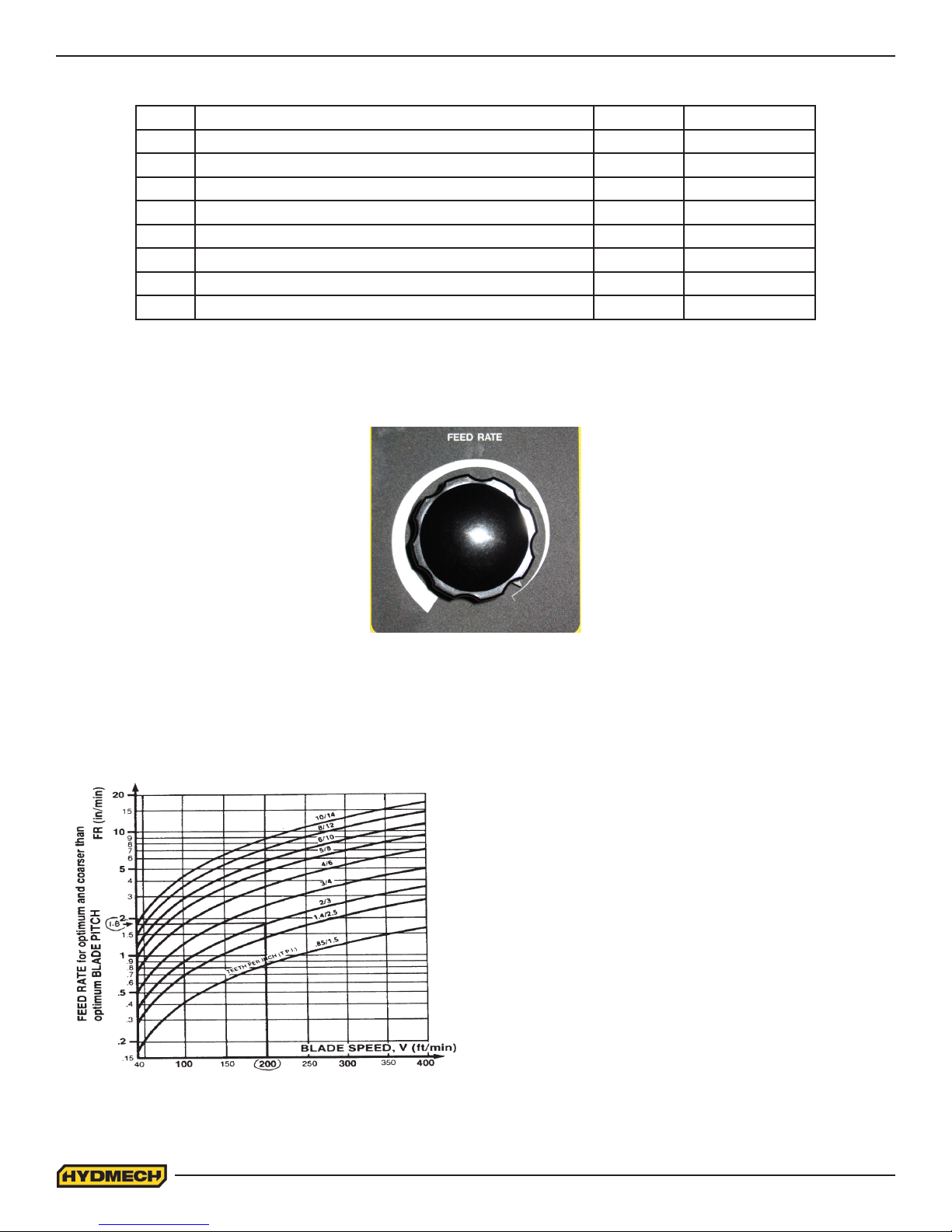
STEP 5: DETERMINE FEED RATE SETTING, FR (in/min) (mm/min).
FEED RATE is the vertical speed at which the blade descends through the work-piece.
The FEED RATE Knob controls FEED RATE of the blade descent. The FEED RATE should be adjusted only in one direc-
tion (from “O” to required value). If you go too far, go back to “O” and come back up. To set FEED RATE for particular
cutting situations use the graph below, which represents the relationship
between FEED RATE, blade speed and blade pitch.
Example #1: It is known from Step 3 that optimum blade
pitch is 2/3, and from Step 4 that blade speed is 200 ft/min
(60mm/min). From the Graph on the left, the FEED RATE is
determined in the following way:
1. On the horizontal axis (blade speed axis), nd
200 ft/min (60mm/min).
2. Find the point where a ver tical line from 200 ft/min
(60mm/min) would intersect the 2/3 blade pitch curve
3. From this intersection point run horizontally left to the
ver tical (FEED RATE) axis, to ar rive at 1.8 in/min
(45mm/min) FEED RATE. Thus 1.8 in/min (45mm/min)
is the FEED RATE for cutting 8” (200mm) diameter 1045
Carbon Steel when the optimum 2/3 pitch blade is used.
Feed Rate Calculation
2.14
Page 33
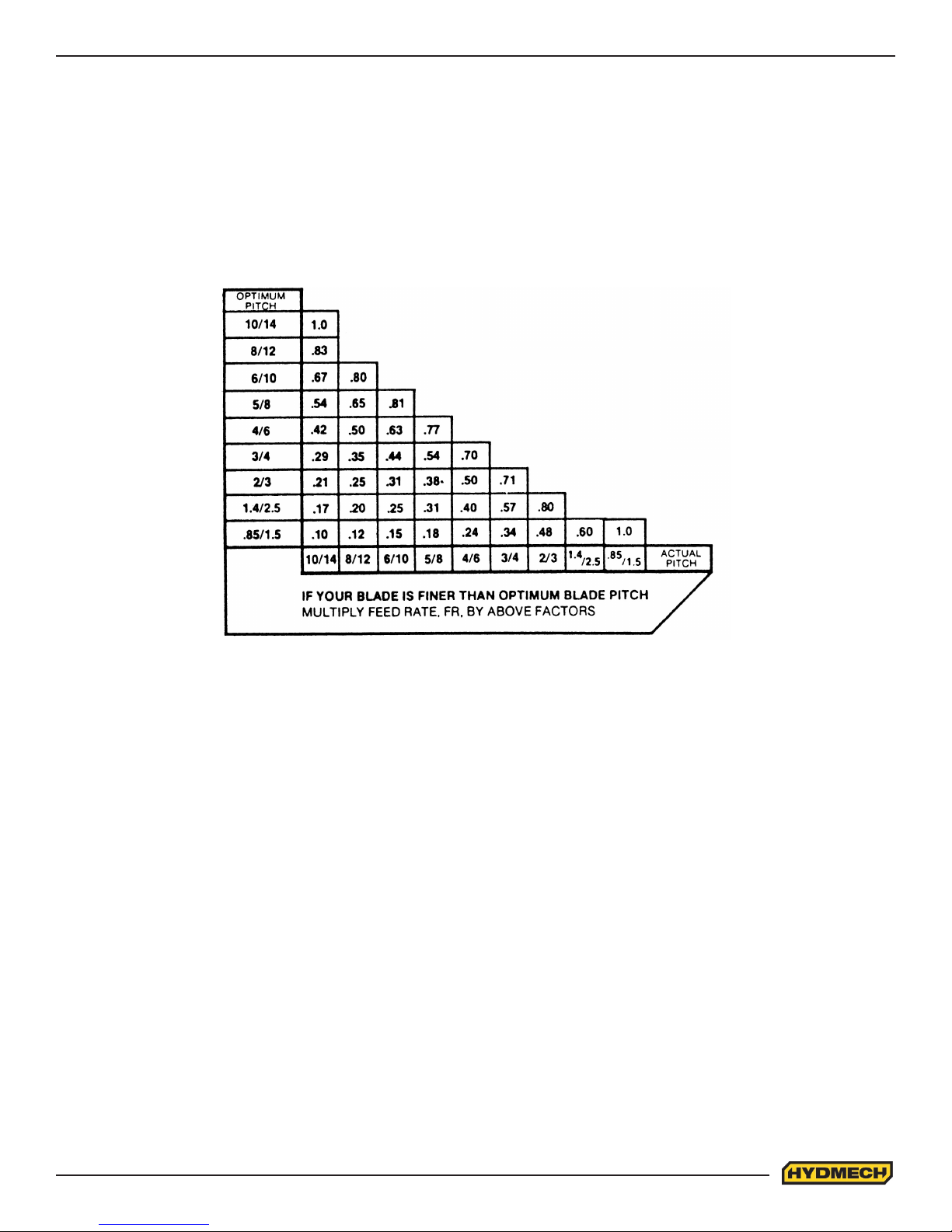
FEED RATE, continued
If the saw is tted with a blade coarser than optimum (e.g.: 1.4/2.5 TPI) we can still use the graph, but we go to the 1.4/2.5
curve. As a result we nd that the FEED RATE is decreased to 1.3 in/min (133mm/min) for this blade. If however, the
machine is tted with a ner than optimum blade (e.g. 3/4 TPI) we use the graph for the optimum blade as before, and
then use a multiplier given by the table below.
Optimum Vs Actual Blade Pitch
ADDITIONAL CUTTING SETUP EXAMPLES
EXAMPLE # 2
Material:
Round Steel Tube SAE 4320 - Hardened to 35 RC (325 Bhn )
Dimensions - 6” O.D. x 4” I.D. (150mm O.D. x 100mm I.D.)
Step 1 Effective Material Width: 4 1/2” (.75 X 6) 114mm (19 x 6)
Step 2 Feed Force limit setting for 6” Diameter material (Refer to Feed Force Limit, Setting in Step 2)
Step 3 Optimum blade pitch (TPI): 3/4 T. P. I.
Actual blade pitch on the saw: 4/6 T. P. I.
Step 4 Optimum blade speed for 4 1/2” effective 225 ft/min (70m/min) material width
Blade speed reduced by hardness factor: 225 ft/min X .60 = 135ft/min (70m/min x .60 = 42m/min)
Step 5 Feed Rate for 3/4 TPI blade: 1.8 in/min (45mm/min)
Feed Rate for 4/6 TPI blade: 1.8 in/min X .70 = 1.3in/min
(reduced by ner than optimum blade pitch factor) (45mm/min x .70= 31.5mm/min)
2.15
Page 34
ADDITIONAL CUTTING SETUP EXAMPLES, continued
EXAMPLE # 3
Material:
Bundle low carbon steel 2” x 2” Tube with 1/4” wall, 12 piece bundle (50mm x 50mm with 6mm wall)
Dimensions: 6” x 8” (150mm x 200mm)
Step 1 Effective Material Width: 5” ( .6 X 8” ) 120mm (.6 x 200)
Step 2 Feed Force limit setting for 8” Diameter material. (Refer to Feed Force Limit, Setting in Step 2)
Step 3 Optimum blade pitch (TPI): 3/4 T. P. I.
Step 4 Optimum blade speed for 5“ effective material width: 320 ft/min (100m/min)
Step 5 Feed Rate for 3/4 TPI blade: 4.0 in/min (100mm/min)
ADDITIONAL CONTROLS
COOLANT FLOW
The main coolant control is found on the control panel.
WASH: Coolant ows any time the machine is under power, permitting wash down with
spray nozzle without running machine.
OFF: No coolant ow.
ON: The coolant ows only when the blade is running or when the blade is running and the
head is descending. This is selectable via the PLC parameters.
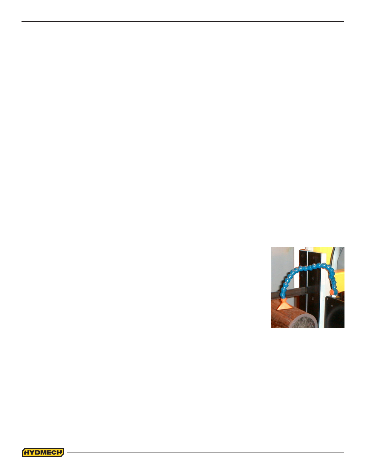
The bandsaw is equipped with two independently controlled coolant spouts that are capable
of supplying a generous ow of coolant to the blade.
The left guide arm supplies a ow of coolant that should ood the blade as it moves through
the carbide pads into the material to be cut. The adjustable spout on the left guide arm
should be set with the blade speed to provide the ood of coolant necessary.
The right guide arm provides a coolant ow through the exible hose that can be pointed
directly where necessary. This exible hose should be used when cutting solid bars, bundles, or wide structurals. Set the
ow of coolant directly into the opening in the material where the blade is cutting.
NOTE:
When cutting materials that do not need constant coolant, such as Cast Iron, some coolant ow is required for blade lubrication to prevent blade scoring by the carbide pads as the blade moves through them.
2.16
Page 35
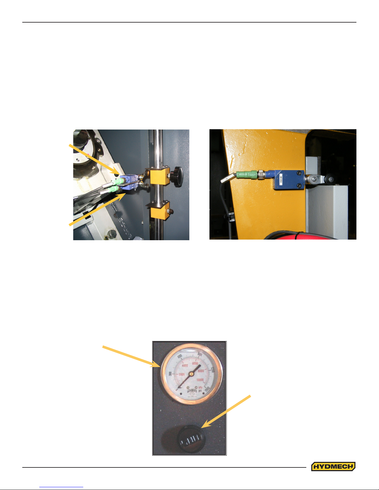
HEAD UP and DOWN LIMIT SETTING
The head up limit is used to restrict the distance the head travels for each stroke. It can be adjusted at any time by moving
the switch trip plate to any position on the vertical bar. The trip plate & switches are found behind the head on the drive
end near the gear box.
Head Up Limit: In order to maximize production in the automatic, cycle the Head Up Limit should be set to just clear the
height of the material.
Head Down Limit: This limit is factory set and under ordinary cutting requirements should not be changed. If changed, it
may cause the machine to malfunction in the automatic cycle.
HEAD UP
LIMIT SWITCH
HEAD DOWN
LIMIT SWITCH
NON CANTED HEAD
6 DEGREE CANTED HEAD
HEAD DOWN L/S MOUNTED ON
MOVEABLE GUIDE ARM
VARIABLE VISE PRESSURE (OPTION)
This option allows the operator to adjust the vise pressure. This can be valuable when cutting light structurals and tubes.
By reducing the vise pressure from the system (H18=1000, H22=1100psi) pressure, distortion of materials is prevented.
The controls are located at the drive end of the machine next to the hydraulic compartment.
Variable vise pressure
read-out gauge
Variable vise pressure controls
2.17
Page 36
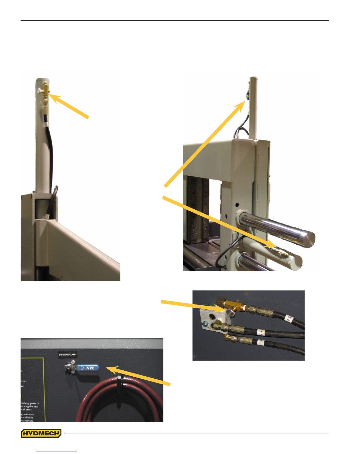
BUNDLING OPERATION (OPTION)
The bundling vises can be operated in direct conjunction with the front and shuttle vises or at a slower clamping speed.
Either bundling can be turned on or off at any time. The on / off valves are shown in the photos.
The speed at which the bundling jaws open and close can be adjusted as required by turning the ow control valves
(shown in the photos) for each bundling cylinder.
FRONT BUNDLING
SPEED ADJUSTMENT
SHUTTLE BUNDLING
AND VISE SPEED
ADJUSTMENT
FRONT VISE SPEED
ADJUSTMENT (LOCATED
ON BACK OF IDLER
SIDE)
FRONT BUNDLING ON/OFF
VALVE LOCATED ON FRONT
OF MACHINE
2.18
Page 37
SECTION 3 – MAINTENANCE
SAFETY DURING MAINTENANCE AND TROUBLESHOOTING
“Lock-out”, or “Lock-out Tag-out” are terms that refer to procedures taken to prevent the unexpected start-up, or other
release of energy, by a machine, whenever anyone is required to remove or bypass safety guards or devices, or
whenever anyone is required to place part of his body in a hazard area.
In almost all jurisdictions, it is required that owners of industrial equipment establish and post lock-out procedures. Know
and use the lock-out procedures of your company or organization. In the absence, of such posted procedures, use the
following procedure.
LOCK OUT PROCEDURE
Whenever work is to be performed on a machine, which requires removal or bypassing of safety guards or devices, or the
placement of part of anyone’s body in a hazard area, the following steps shall be taken:
1. Operator shuts down the machine.
2. The supervisor in charge of the machine must be informed of the intention to Lock-out the machine.
3. The FEEDER power which supplies power to the machine and which is connected to the machine via the
Power Junction Box (see picture below) must be turned OFF and locked in the OFF (0) position by means of
a padlock. The key for this padlock must be kept by the person performing the work on the machine. If more
than one person is performing work on the machine, then a multiple lock hasp shall be used, and each person
shall apply his or her own lock to the hasp.
4. The Machine Power Disconnect Switch must be turned OFF, and locked in the OFF (0) position by means of
a padlock. The key for this padlock must be kept by the person performing the work on the machine. If more
than one person is performing work on the machine, then a multiple lock hasp shall be used, and each person
shall apply his or her own lock to the hasp.
5. Prior to starting any work on the locked-out machine, the supervisor shall attempt to start the machine to
ensure that the lock-out device provides adequate protection. Operating controls must be reset to the “OFF”
position after this test.
6. Work on the locked-out machine may now proceed.
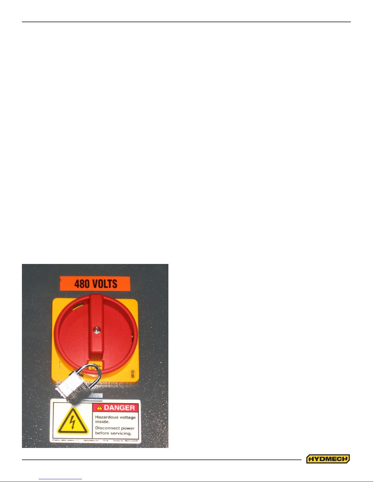
H18 & H22
MACHINE DISCONNECT SWITCH USED FOR SAFETY
LOCKOUT PURPOSES
Machine Power Disconnect located on the lid of the machine
control box.
1. Ensure switch is in the OFF position.
2. Install padlock and lock it.
3.1
Page 38
RESTORING MACHINE TO USE
After completion of all repairs or maintenance to the locked-out machine, it shall be restored to use as follows:
The person(s) who performed the work shall verify that all areas around the machine are safe, before the machine is
re-energized. No-one shall be permitted in un-safe areas around the machine. All guards and covers shall be properly
installed.
Each lock-out padlock shall be removed by the person who applied it.
After the lock-out padlocks are removed, and before the machine is started, the supervisor and all other employees who
use the machine, shall be informed that the lock-out has been removed. After notication is made, the machine may be
re-started.
BLADE CHANGE MODE PROCEDURE
Wear safety glasses, gloves, and a long sleeve shirt for protection when handling band saw blades during blade change.
NOTE THAT GLOVES SHOULD NEVER BE WORN NEAR A RUNNING BANDSAW BLADE. When handling new blades,
or ones that will be re-used, it is important to keep the teeth out of contact with concrete oors.
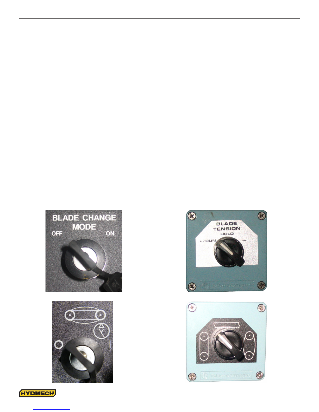
This machine is equipped with a hydraulic blade tension selector switch and a ‘Blade Change Mode’ key switch, located
on the operator control panel. The description of the switch functions will either be in English or portrayed as a pictogram.
(See pictures below)
The blade change mode keyswitch has two positions:
OFF or O – All normal operations of the band saw are operative.
ON or I – Hydraulic motor can be started.
Blade tension is operative.
3.2
Page 39

BLADE REMOVAL
1. With the blade change mode key switch in ‘OFF’, the blade stopped and the hydraulics ON, raise the saw head
until the drive door will clear the electrical control panel.
2. Open the front vise about 12”. This will provide room between the two guide arms to easily grasp the blade with
two hands, BUT DO NOT TOUCH THE BLADE UNTIL THE BLADE CHANGE MODE SWITCH IS TURNED TO
THE ‘ON’ POSITION.
3. Turn the blade change key switch to the ‘ON’ position. The hydraulics will continue to run, but only the blade
tension switch is functional. The blade wheel doors can be opened without the hydraulics shutting down.
4. Remove the blade guard.
5. Open both blade wheel doors.
6. Release the blade tension by turning the switch briey to ‘ – ‘. The blade tension switch also opens and closes
the hydraulic blade guides. By jogging the switch between ‘HOLD’ and ‘ – ‘, it is possible to regulate the degree of
tension on the blade.
7. Pull the top strand of the blade down out of its slot above the cutting area and forward out of the slots on the
inside walls of the blade wheel housings.
8. Pull the lower strand of the blade down out of the blade guides.
9. Store and dispose of the used blade.
BLADE INSTALLATION
NOTES ABOUT NEW BLADES
• A new blade will come folded into a compact coil. Follow the blade manufacturer’s instructions for safely unfolding
the blade.
• The blade must be installed with the teeth facing towards the front of the saw where it passes around the wheels,
and with the teeth in the cutting area pointing towards the drive wheel. This may require that the blade be turned
inside out before installation.
1. With the blade change mode key switch remaining in the ‘ON’ position, turn the blade tension switch to the ‘ – ‘
position for several seconds until the idler wheel has fully retracted and the blade guides have fully opened.
2. Insert the lower strand of the new blade into the blade guides and briey turn the blade tension switch to the
‘ +/RUN ‘ position. This will close the hydraulic guides and assist in holding the blade in the guides.
3. Lift the upper strand of the blade up into its slot above the cutting area, and place it around the blade wheels.
4. Turn the blade tension switch briey to ‘ +/RUN’ and then leave it in ‘HOLD’ to retain the blade lightly on the
wheels.
5. Adjust the blade position on the wheels so that the blade is not crooked on them and the teeth overhang the front
edge of the wheels.
6. Turn the blade tension switch to ‘+/RUN’.
7. Close both blade wheel doors.
8. Turn the blade change mode key switch to the ‘OFF’ position. The hydraulics will shut down.
9. Switch the hydraulics on, then start the blade and run for 20 seconds.
10. Stop the blade.
11. Turn the blade change key switch to the ‘ON’ position.
12. Open the blade wheel doors and inspect the blade tracking, plus the position of the blade brush. Refer to the
manual for tracking adjustments.
13. Close the blade wheel doors and turn the blade change mode key to the ‘OFF’ position.
14. Blade change procedure is now complete.
3.3
Page 40
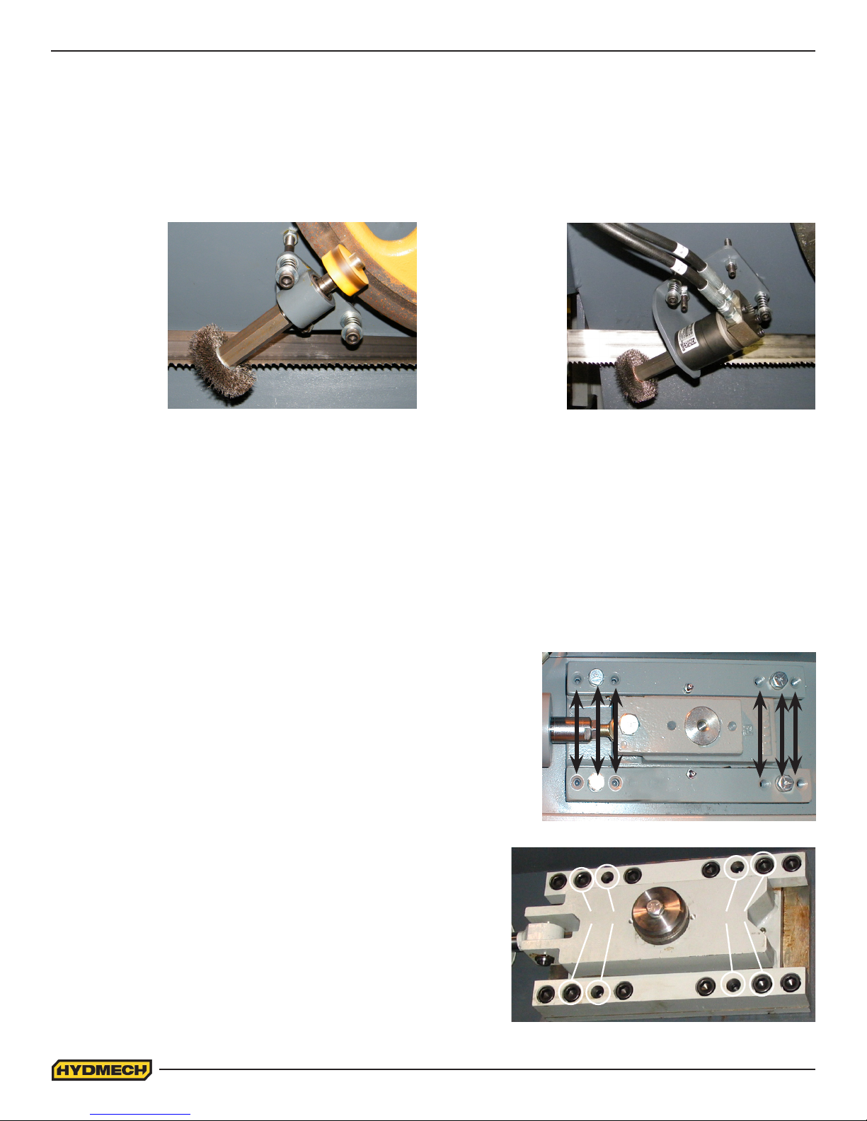
BLADE BRUSH ADJUSTMENT
The blade brush is properly set when machine leaves the factory, but it wears out during operation and needs to be
readjusted periodically. The blade brush assembly is found behind the drive side door and is shown below. To adjust the
assembly, loosen the hex nut, turn the setscrew counterclockwise until the wires on the brush touch the bottom of the
blade gullets and tighten the hex nut.
The brush should be replaced as it becomes worn to approximately 70% of it’s original 3” diameter. Replacements can be
purchased through your Hyd·Mech Dealer.
H18 SV
BLADE BRUSH
H22 SV
BLADE BRUSH
BLADE TRACKING ADJUSTMENT
For an H-18, blade tracking is set so the teeth of the blade protrude .260±.01” (6.6±.25mm) from the face of the wheels.
For an H-22, blade tracking is set so the teeth of the blade protrude .310±.01” (6.6±.25mm) from the face of the wheels.
IDLER WHEEL TRACKING
Release blade tension before adjusting. Adjust tracking by regulating “push” set screws and “pull” bolts. Loosening bolts
“A” and turning in set screws “C” by equal amounts will move the blade OFF the wheel. Loosening bolts “B” and turning in
set screws “D” by equal amounts will move the blade ON to the wheel. After each “C” or “D” set screw adjustment, tighten
bolts “A” or “B”, turn tension switch to “+RUN”, run the
blade for a moment and recheck the tracking.
C A C D B D
Note: Check the proximity sensor distance from the wheel
target or spokes before starting the blade drive. Failure to
do so may result in damage to the sensor.
H18 SV
H22 SV
3.4
A BC D
Idler wheel tracking bolts & set screws
Page 41
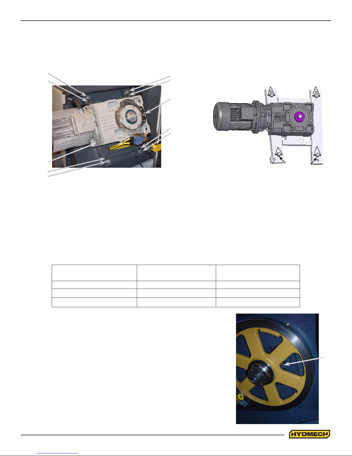
DRIVE WHEEL TRACKING
Release blade tension before adjusting. Loosening bolts “A” and turning in set screws “C” by equal amounts will move the
blade OFF the wheel. Loosening bolts “B” and turning in set screws “D” by equal amounts will move the blade ON to the
wheel. After each “C” or “D” set screw adjustment, tighten bolts “A” or “B”, turn tension switch to “+ RUN”, run the blade for
a moment and recheck the tracking.
B
D
A
C
D C
H18SV
E
D
B
F
H22SV
C
A
B
D
B
A
C
A
GEARBOX LUBRICATION (H-18ASV WITH A503 GEARBOX, H-22ASV WITH A603 GEARBOX)
The Bonglioli A503 gearbox used on the H18 is supplied with 8.4 litres (2.22 US gallons) of Mobil SHC 634 synthetic oil.
This oil has an ISO Viscosity Grade of 220 that is optimum for ambient temperatures from 20 – 40 Deg C [70 – 104 Deg
F]. If the machine will be operated for prolonged periods at ambient temperatures below 20 Deg C [70 Deg F] an oil of ISO
Viscosity Grade 150 should be substituted.
Because of the tilted orientation of the gearbox on the H18 and H22 saws, the correct oil level is about 1 inch below the
level plug, F, shown in the illustration.
The suggested oil change interval is given below:
Note: The H-22ASV with the A603 gearbox requires 15
litres (3.96 US gallons) of Mobil SHC 634 synthetic oil.
Oil Temperature
Deg C [deg F]
Mineral Oil Interval
[hours]
<65 [< 150 F ] 8000 25000
65 – 80 [150 F – 175 F] 4000 15000
80 – 95 [175 F – 200 F] 2000 12500
Oil can be changed by draining through plug, E, and lling at plug F. If the type
of oil is being changed, it is advisable to ush the old oil by lling the box with
the normal quantity of the new oil, running it briey at moderate speed, and then
draining the box again, before re-lling it with a fresh quantity of the new oil.
OUTPUT SHAFT LUBRICATION
Always follow Lock-out Procedures before performing this lubrication.
Band tension load is carried by a grease lubricated spherical bearing. A grease
tting is accessible through the spokes of the blade wheel, as shown at point G in
the accompanying illustration. Lubricate once per year with 30 ml [1 uid once] of
NLGI Class 2 Lithium base mineral oil grease. This quantity represents about 20
to 30 strokes of a typical hand grease gun.
Vise jaw guides, infeed rollers and bundling assemblies also require periodic
greasing.
Synthetic Oil Interval
[hours]
G
3.5
Page 42
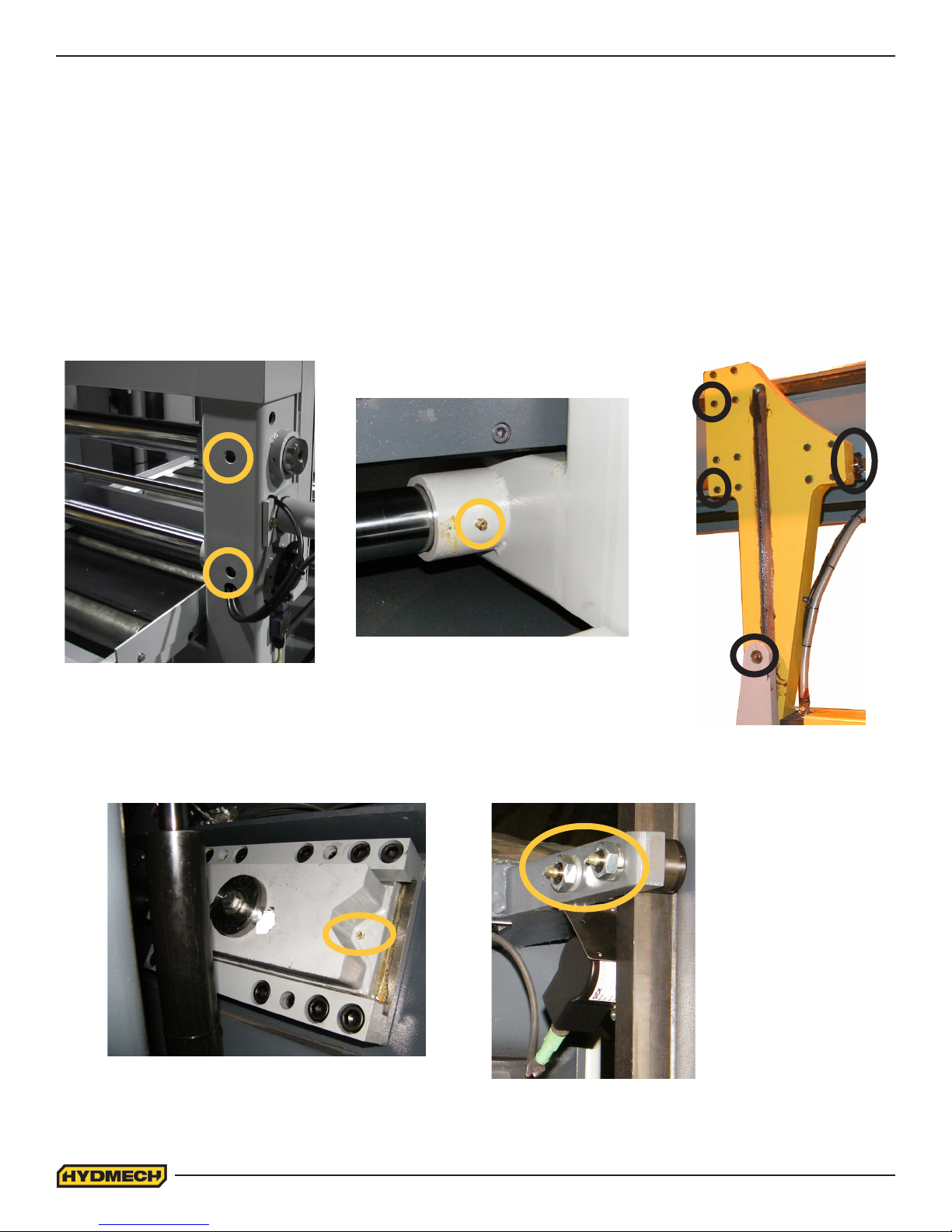
CAM FOLLOWER ADJUSTMENT
There are two cam followers mounted on the head frame. The set of cam followers are shown below. One of them is xed
and the other is adjustable. The cam followers are factory set and usually do not require adjustment. In a properly
adjusted system of cam followers only one side should be in contact with the guide. The gap between the other and the
guide bar should be 0.003” – 0.005”. If it exceeds 0.005” you should contact your dealer to arrange for adjustment.
LUBRICATION
The design of the machine was intended to minimize maintenance, although periodically certain moving parts need
lubrication. We recommend that this periodic lubrication be done once a month using any general purpose grease. In
addition to the grease points shown, vise jaw guides, in-feed rollers and bundling assemblies require greasing.
2 SHUTTLE VISE GREASE NIPPLES
IDLER WHEEL TENSIONER
(ONE AT BOTH ENDS)
2 SHUTTLE
SHAFT BEARING HOUSINGS
4 GUIDE ARM GREASE
POINTS
CAM FOLLOWER GREASE
NIPPLES
3.6
Page 43
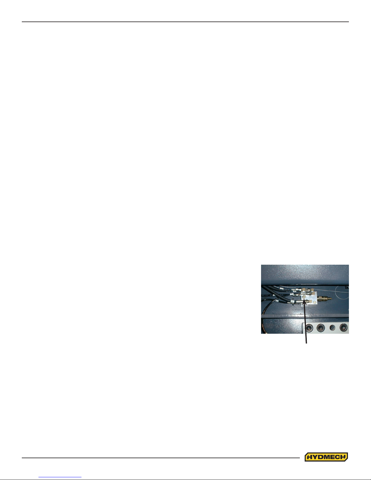
HYDRAULIC MAINTENANCE
1. OIL FILTER- Ten micron ltration of the oil is provided by a spin on type lter mounted on the tank return line. The
element should be changed after the rst 50 hours of operation and then every 500 working hours. See section 5 for
replacement lter element information.
2. HYDRAULIC OIL- Machine hydraulic reservoir is lled with mineral oil Texaco Rando HD46. In case of changing the
brand, hydraulic system should be drained and thoroughly ushed. Following is a list of recommended replacement oils:
•TEXACO RANDO HD 46
•CHEVRON ECO Hydraulic oil AW ISO 46
•MOBIL DTE 25
•ESSO NUTO H46
•SHELL TELLUS OIL 46
3. HYDRAULIC OIL LEVEL - Oil level should be maintained in the upper half of the level gauge. Normally the rate of oil
consumption will be very low and it should be unnecessary to add oil more often than at lter changes if at all.
4. HYDAULIC OIL CHANGE - Oil visual inspection should be conducted with every lter change for following signs of
degradation:
•Milky or hazy oil color
•Burnt smell
•Varnish or sludge formation
•Increased viscosity
If one of the above is observed then oil should be changed. It is recommended to change oil after every 6000
hours of operation or every 2 years.
5. OIL TEMPERATURE - Oil temperature is indicated by a thermometer contained in the level gauge. Oil temperature
during steady operation should stabilize at about 50-55F (28-31 deg C) above room temperature. Thus in a
70F (21 deg C) shop one might expect an oil temperature of about 120F (49 deg C). Oil temperature should never exceed
155F (68 deg C).
6. HYDRAULIC PRESSURE - Hydraulic pressure is factory set and should not require any further attention. For correct
pressure see hydraulic schematic.
7. BLADE TENSION – Blade tension pressure is factory set and should not require
any further attention. For correct pressure see hydraulic schematic.
8. CARBIDE PRESSURE - Carbide lock pressure is factory preset:
•H-18SV 300 – 400 PSI
•H-22SV 150 – 200 PSI
The pressure gauge is not provided. There is a separate port to hook up a gauge if
setting needs to be veried or corrected.
CLEANLINESS
Gauge Port
The heavy duty design should endure heavy operating conditions and provide the customer with awless machine
performance. To extend good performance some care is required especially as cleanliness is concerned.
The following areas should be kept clean:
•Control console free of dirt and grease.
•Door charts free of dirt and grease.
•Wheel boxes free of chips.
•Blade guides free of chips.
•Out-feed table free of chips.
•A large chip build-up should be avoided in the base of the saw.
NOTE:
All parts must be cleaned before any repair service can be performed on them.
3.7
Page 44
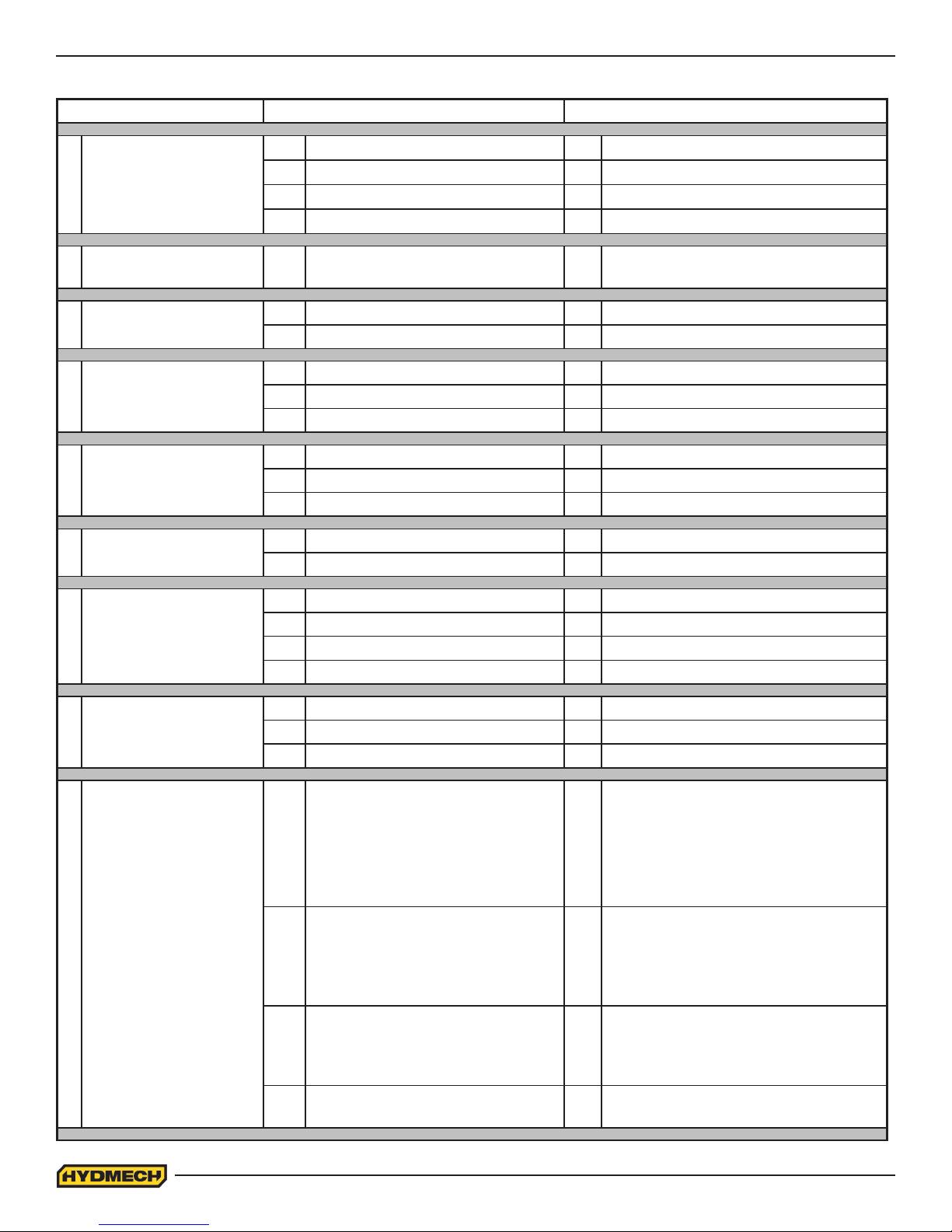
TROUBLESHOOTING
PROBLEM PROBABLE CAUSE SOLUTION
Saw is cutting out of
1
square vertically.
Saw is cutting out of
2
square horizontally.
1a. Blade worn. 1a. Replace blade.
1b. Low blade tension. 1b. Tension blade.
1c. Blade guides. 1c. Check for worn guides.
1d. Excessive feed rate. 1d. Reduce.
2 Stock not square in vises. 2 Adjust accordingly.
3 Blade comes off wheels.
4 Blade stalls in cut.
Blade vibrates
5
excessively.
Excessive blade
6
breakage.
7 Tooth strippage.
8 No coolant ow.
3a. Not enough blade tension. 3a. Reset blade tension.
3b. Improper tracking. 3b. Set tracking.
4a. Not enough blade tension. 4a. Tension blade.
4b. Excessive feed force. 4b. Reduce.
4c. Excessive feed rate. 4c. Reduce.
5a. Blade speed too fast. 5a. Reduce.
5b. Guide arms too far apart. 5b. Adjust accordingly.
5c. Not enough blade tension. 5c. Tension blade.
6a. Excessive blade tension. 6a. Reduce blade tension.
6b. Excessive feed rate. 6b. Reduce.
7a. Blade pitch too ne. 7a. Select coarser pitch.
7b. Blade brush not cleaning. 7b. Adjust or replace blade brush.
7c. Excessive feed rate. 7c. Reduce.
7d. Excessive feed force. 7d. Reduce.
8a. No coolant. 8a. Add coolant.
8b. Coolant line blocked. 8b. Blow out coolant line.
8c. Coolant pump inoperable. 8c. Check, replace if faulty.
9a. Safety relay is not energized 9a.
9 Saw will not start.
9b. Motor overload has tripped. 9b.
9c. Control circuit fuse has blown. 9c.
Vise or head selector switch not in
9d.
the center (neutral) position.
3.8
1.Ensure all Emergency Stop push
buttons are released.
2.Ensure Door interlock switches are
not activated.(Close Drive & Idler doors)
Depress each of the over-load buttons
located in the electrical box. Depressing
one button at a time and trying to start
the saw will indicate which motor was
overloaded.
Replace the fuse in the control panel.
Random blowouts may occur but a
quickly repeated blowout points to an
internal wiring fault.
Turn all switches to the center (neutral)
9d.
position.
Page 45
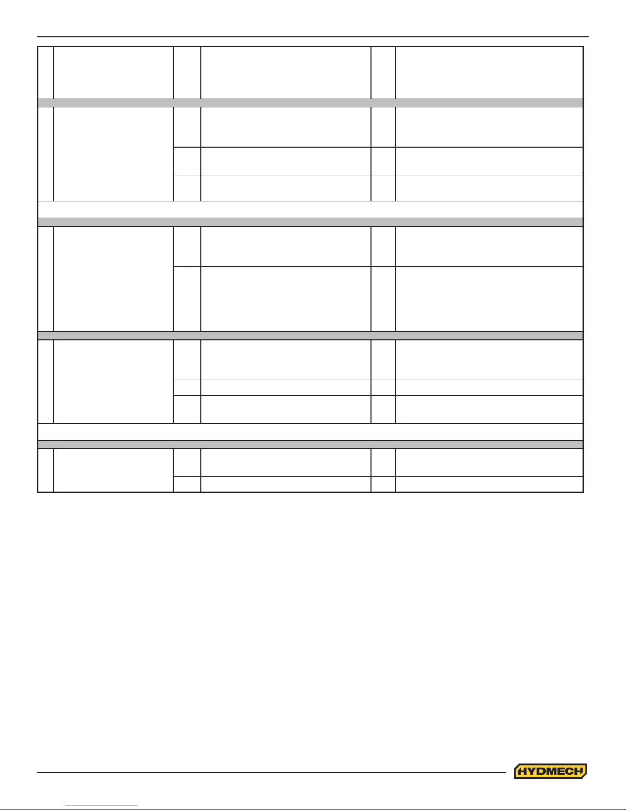
Saw starts but will not
10
run after Start button has
been released.
On machines so equipped, the out-
10
of-stock or blade breakage limit
switch has been tripped.
Reload with stock or reset the blade.
Hold the hydraulic start button and
10
release the blade tension or open vises
far enough to deactivate the limit switch.
Saw starts but no
11
hydraulic functions.
IN MANUAL MODE
No individual function will
12
respond to its manual
control switch.
13 Head will not descend.
IN AUTOMATIC MODE
If blade wheels run clockwise, wrong
11a.
phase order in power connection to
saw.
If pump is noisy cause may be low
11b.
hydraulic oil level.
Stop immediately; reverse any two of
11a.
the three phase connections.
Stop immediately, add hydraulic oil.
11b.
(See “Hydraulic Maintenance”)
11c. Pump-motor coupling has separated. 11c. Adjust accordingly.
Observe pilot light(s) on relevant
12a.
valve. If pilot light fails to go on,
problem is electrical.
If pilot light related to inoperative
function does light, problem may
12b.
still be the coil . If problem remains
it may result from dirt in the valve
spool.
Feed Rate Valve is fully closed -
13a.
pointer is set on “0” or close to “0” in/
min.
This requires the attention of a qualied
12a.
service person.
Disassembly of hydraulic valves should
be under taken only by qualied service
12b.
personnel or those knowledgeable with
hydraulic components.
Turn Feed Rate Knob in a counter
13a.
clockwise to open valve.
13b. Feed Force Limit is set too low. 13b. Increase Feed Force Limit.
Check for physical interference
13c.
preventing the head from falling.
13c. Remove obstructions.
14 Auto cycle will not start.
14a. No job queue programmed to run. 14a.
Enter job numbers(s) and job data as
described in Section 2.
14b. Pieces required equals pieces cut. 14b. Clear pieces cut.
3.9
Page 46

PROGAMMABLE LOGIC CONTROL
Note:
The PLC is equipped with a lithium battery to keep the program stored while the power is shut down. The battery will need
to be replaced every 3 to 5 years, depending on the usage. A visual warning will be displayed on the interface when the
battery drains to a certain level. Batteries can be purchased through your Hyd·Mech distributor.
The programmable logic control uses signals from limit switches, control panel switches, encoders (rotary shaft or linear)
and information that is programmed into it to supply accurate automatic length control and sawing functions.
The inputs used include:
• Head up limit switch
• Head down limit switch
• Machine function switches and push buttons
• A signal from the auto/manual push button (tells the PLC whether auto or manual operation has been selected).
An encoder is attached the shuttle assembly and travels with the shuttle to provide length information to the PLC. A
proximity sensor is mounted through the rear of the idler wheel box. A target for this sensor is mounted on the back of the
idler wheel, or, all six spokes of the wheel may be targets to provide blade speed input to the PLC.
The programmed information includes logic put into the PLC by the manufacturer, as well as information programmed into
it, through the keypad during assembly. Information from the plant is referred to as the parameters. The parameters are
important for the PLC to provide accurate sawing lengths and blade speed display. The following is a description of each
parameter and the procedure to access them.
To view the PLC parameters:
In manual mode, with the front vise switch in the “close” position press FWD and REV key simultaneously (not more the
0.5 sec apart). The PLC will prompt you for a password that can be obtained from the Hyd·Mech Group Limited Service
Dept. If the password is correct, a screen of parameters will appear. The display will show four lines of parameters at a
time. If the length control calibration is necessary, follow the calibration procedure in this section. To move through the
parameters use the cursor keys to scroll up or down. To change a parameter, cursor to that parameter line and using the
number keys type in the new value and press enter. To leave the parameters press the Auto/Man key.
3.10
Page 47

PLC PARAMETERS
SPEED CONST
Blade speed adjustment number. If the actual blade speed is different than the displayed blade speed, a new speed factor
will need to be calculated (providing the WHEEL TRGETS parameter is set correctly). Actual speed ÷ display + adjustment
factor X existing speed factor = New Speed Factor
WHEEL TRGETS
Number of targets per revolution of the idler wheel. Can be toggled either 1 or 6.
HGT CLB (Press Enter)
This is to be used only if calibration is required. Call Hyd·Mech Service department for instruction.
ACTUAL HGT
Actual Height Value. Value entered after performing height calibration procedure (described later in this section). This
value represents the head full stroke height.
HGT CONST
Height constant. Species linear distance of head movement in inches per one pulse of head encoder.
LTH CLB (Press Enter)
Length calibration. This is to be used only if calibration is required. Call Hyd·Mech Service department for instruction.
ACTUAL LTH
Actual Length Value. Value entered after performing length calibration procedure (described later in this section). The
PLC uses this value to calculate its length encoder resolution and stroke parameter. Note: If Calibration Procedure is
activated and not completed, or activated and a value not entered for ACT LTH, this value will reset to 00.000 and the PLC
will not be able to count/display lengths.
LTH CONST
Length constant. Species linear distance of shuttle movement in inches per one pulse of shuttle encoder.
ACCEL DIST
Shuttle acceleration distance. Distance, in inches, the shuttle will travel slowly before reaching fast speed while starting to
move in either direction. (i.e. 1.000).
DECEL DIST
Shuttle deceleration distance. Distance, in inches, the shuttle will travel slowly reaching before home or target position.
(i.e. 1.000)
MIN FST DIST
Minimum fast speed distance. If the programmed length is smaller than this parameter, the shuttle will only move in slow
speed.
TARGET WINDOW
Allowable +/- tolerance from programmed length.
FVO DWELL
Delay time for the opening of the xed VISE in seconds.
SVO DWELL
Delay time for the opening of the shuttle VISE in seconds.
CLOSE TIME
Delay time for the closing of the shuttle or xed VISE in seconds.
3.11
Page 48

FEED RATE
Activates feed rate display. Not active on S20A, S23A and H10 machines.
ACTUAL POSITION
If this value is set to “YES,” displays shuttle vise actual position.
HOLD SHT HOME
Hold shuttle VISE home and closed during cut.
BRKN PROX
Allows user to override signal from proximity sensor in case it is broken. (When set to “NO” machine will not run with
broken proximity sensor. Set to “YES” allows machine to run).
MIN BLD SPEED
Minimum blade speed on which the PLC will detect the that blade is running.
SPD PROX DELAY
Delay in monitoring of the blade speed proximity sensor during acceleration of the blade from start to desired speed set by
the potentiometer.
POWER DWN TIMER
If “0” selected, then the machine will shut down after the job is completed. This will allow the machine to continue running
for a specied time after the job (in Manual Mode) or the cycle (in Auto Mode) has been completed. Range is from “0” to
“180” minutes.
BLADE CLEAR
If set to “YES,” when the AUTO cycle reaches the function of head up, the shuttle will retract the material from the blade
by 1/8” before the head will move up. When the head reaches the up position the next length of material is shuttled into
position.
TRIM CUT
If “YES” selected the machine will perform a facing cut of the material at the beginning of an automatic cycle.
OUT OF STOCK
Selecting “yes” activates the out of stock option, which prevents the shuttle vise from closing if insufcient length of
material is available for the next length advance. Also stops the automatic cycle if there is insufcient length of material.
COOLANT
When “BLD” selected, coolant ows when the blade is running. When “BLD+ DWN” selected, coolant ows when the
blade is running and head is moving down.
QUEUE
The queue allows the operator to run several jobs (max 5) in series. If “REPEAT” is selected the above series will be
executed the selected number of times.
3.12
Page 49

PLC TROUBLESHOOTING
Problem 1 (for automatic models with a shuttle)
PLC is not measuring lengths
Possible causes:
1. Encoder
a. Pinion gear is loose on the encoder shaft
b. A bad encoder
2. Encoder Cable
a. Bad connections at the encoder or the PLC
b. Open or shorted wire.
3. PLC Unit
a. Damaged hardware
4. Display unit
a. No power from the PLC unit
b. Damaged hardware
5. Actual Length (Actual LTH)
a. The parameter value is set to 00.000. Perform a self-calibration procedure and enter the value.
Diagnosis:
1. With the machine in MANUAL mode, bring the shuttle forward to the home position and clear the length display so it
reads “0.000”. Run the shuttle, in slow speed, to the rear of the machine and back to the home position. Make sure you
move in full complete strokes.
a. The length should accumulate on the display as a positive number when the shuttle is moving away from the blade
and should count back to 0 when coming back. If this is not the case then reverse the green channel wire on the encoder
with the white channel wire.
b. If the display alters between 0.000 and ± 0.001, then the encoder channel is not being recorded correctly.
2. To determine the cause, rst, check the encoder cable connections at both ends to be sure all four wires are connected
properly.
3. Measure the voltage:
a. At the encoder connector. Between 0 Volt pin and 24 Volt pin. This voltage should be a minimum of 22 VDC to 26
VDC.
If the voltage is incorrect, check the encoder cable continuity. If it is ok, there is possible PLC problem.
If the voltage is correct then proceed to the next step.
b. At the encoder connector. Between 0 Volt pin and channel A pin, and, between 0 Volt pin and channel B pin. This
voltage should be slightly less then the supply voltage at each channel
If the voltage is incorrect at this point, check for proper continuity of these wires and repair as necessary.
Note:
When checking the encoder cable for continuity, each wire should also be checked for shorting to ground and or to each
other. If the voltage to the encoder is correct, proceed to the next step.
4. At the encoder connection of the PLC, between the 0 volt and A&B channels, with the shuttle moving slow, the
voltage should be approx. 10 to 13 VDC. Input LED’s X0 and X1 should icker or go dim with the shuttle moving. If these
LED’s show no change with the shuttle moving, the encoder is likely at fault. Check that the pinion gear is securely
fastened to the encoder shaft and that it can rotate along the rack as the shuttle moves.
If all mechanical components are functioning correctly then the encoder is defective.
If all test check positive, the problem is in the PLC unit.
3.13
Page 50

Problem # 2 (for automatic models with a shuttle)
Inaccurate Lengths in Auto Mode
Possible Causes:
1. Encoder
a. Pinion not engaging the rack all the way from front to back.
b. Mechanical interference.
c. Pinion loose on the encoder shaft.
2. Encoder Cable
a. Bad connection at encoder or at the PLC.
b. Intermittent open in one or more signal wires.
3. Improper programmed information
a. Existing parameter(s) incorrect.
b. Incorrect blade kerf.
4. PLC
a. Faulty PLC unit (not repairable in the eld)
GENERAL RULES
Normally, three types of length inaccuracies may occur.
1. Inconsistent
a. Lengths cut are not consistent, error changes. It doesn’t matter how long the part required is the error is never
the same.
b. Cause: Most likely a defective electrical, hydraulic or mechanical component.
2. Consistent
a. Lengths cut are consistent and the error is also consistent. The error always stays the same regardless of part
length.
b. Cause: Kerf Value
3. Linear
a. Lengths cut are consistent but the error increases as the part length increases. The longer the part the greater
the error.
b. Cause: When the self-calibration is executed, an incorrect “ACT LTH” value was entered.
Diagnosis:
• Check and record the existing parameters. Also check for proper blade kerf. By making a cut part way into a piece
of material and measuring the width of the cut, the operator can check the blade kerf.
INCONSISTENT INACCURACY
• With the machine in Manual mode, move the shuttle all the way forward and clear (zero) the length display. Move
the shuttle in reverse, in slow speed, all the way to the end of its travel. Return the shuttle forward to the home position,
also in slow speed. The display should read 0.000” ± 0.005”. Do this test several times to be sure the read-out is repeatable.
Diagnosis:
Following the same procedure, run the shuttle alternating between fast and slow speed going back and forth. Again the
display should be able to read 0.000” ± .005” when returning to the home position.
3.14
Page 51

If the display does not read as specied:
• Check the encoder pinion gear to be sure it can run smoothly down the rack and that the gear and rack teeth engage
over the entire travel of the shuttle.
• Check that the pinion gear is tight on the encoder shaft.
• Check the encoders cable connections, a loose connection could easily cause this concern.
• Remove the encoder from the machine and check that the shaft can rotate freely. There should be no binding or rough
spots felt when spinning the shaft. Plug the encoder cable into the encoder, clear the length display and rotate the shaft as
closely as possible to one revolution. The display should ready 3.142” (positive or negative depending on the direction you
rotated). Repeat this test 3 or 4 times, spinning the shaft several times between tests.
CONSISTENT INACCURACY (make sure the blade kerf value is correct)
Change the “ACTUAL POS” parameter to YES. This will make the PLC show actual shuttle travel in AUTO
With no material in the machine:
1. Program JOB 1 for 2 pieces of 5” in length. JOB 2 for 2 pieces of 10” in length and JOB 3 for 2 pieces of one
complete shuttle stroke length.
2. Enter JOBS 1 to 3 into the QUEUE.
3. Record measurements on the display each time the shuttle vise reaches the target length and closes. It should equal
the required length plus the programmed kerf. Check that this measurement is ± .002” for each length. If the
overshoot / undershoot is very inconsistent, it could be related to an incorrect shuttle cushion period. This may be caused
by “DECEL DIST” parameter being set to low, defective fast or reverse output relays on the PLC, or the hydraulic cushion
valve (located at the hydraulic manifold) may be faulty.
LINEAR INACCURACY (not valid for machines with linear encoder)
Load machine with a piece of stock for test cutting
Open the parameters screen
Initiate the length calibration procedure
Re-enter the new “ACT LTH” (actual length) value
Re-cut test lengths and check if accuracy is satisfactory
Note:
Linear inaccuracy may be corrected in two ways, by using the length calibration as described or by adjusting the LTH
CONST as follows:
Load the machine with a piece of stock for test cutting
Program he PLC to cut two pieces of 1”, 12” and a length equal to a shuttle and a half of the machine being checked.
Make the cuts and measure as accurately as possible.
Using the formula provided, calculate the new parameter “LTH CONST”
Formula for determining new parameter “LTH CONST”
Measured length ÷ programmed length x existing constant = new “LTH CONST”
i.e. Programmed length =1.00” Measured Length =.99” -.001”
=12.00” =11.988” -.012”
=60.00” =59.940” -.060”
Existing parameter for LTH CONST = 0.001256
11.988 ÷ 12.00 x .0012566 = 0.001255
The new parameter LTH CONST value would then be 0.001255. This value should be entered and the test repeated.
Adjust the parameter as necessary.
GENERAL RULE:
Lowering the parameter value = longer shuttle travel = longer parts
Increasing the value = shorter shuttle travel = shorter parts
3.15
Page 52

Problem 3
Auto Cycle Not Being Completed
In auto mode, the PLC controls the saw functions through output relays. For a certain function to be actuated, the PLC
must rst see specic input(s). Like the output relays, the input relays are located on the PLC unit. Directly beside the
input and output terminals are red LED’s (Light Emitting Diode), which will light up when the corresponding input is being
received or output being actuated. Observation of these input/output LED’s can help diagnose auto cycle problems. Refer
to the PLC inputs and outputs in this section. When a problem occurs in the auto mode, the lights should be checked to
see if they are coming on at the proper time or if they are coming on at all.
Input LED’s
If a specic input light does not come on when expected
• Check for a faulty/misadjusted limit switch, push button, encoder or faulty wiring or connections.
• Wiring for each limit switch should be connected from the VDC terminal connection to the particular limit switch,
and from the limit switch to the input connector of the PLC.
Note:
All inputs are denoted by an “X”
All outputs are denoted by a “Y”
The following is information on output diagnosis and the sequence of inputs and outputs during the auto cycle.
Auto Cycle Sequence:
After the mode push button is in the auto position, the job has been programmed into the PLC, and the cycle start push
button pressed:
1. Hydraulics running, the head should move to its up limit if it is not already there. The shuttle vise should open and
come forward to the home position. HUP input light must come on for the cycle to continue.
a. HUP input on – cycle should continue, if not check outputs per step 2.
b. HUP input not on – Check that the head up limit switch is being activated. Check the limit switch/limit switch
wiring.
2. Front vise should be closed; the shuttle vise should stay open and move back to the programmed length.
a. FVC output should be on and SVO output will light momentarily, REV output and FST output should be on when
the shuttle moves back fast.
3. As the shuttle approaches the target length the FST output should shut off and the shuttle should travel slowly for the
DEC DIST parameter (cushion distance). When the shuttle reaches the target length the SVC output should light and the
shuttle vise should close on the material.
4. FVO output light should momentarily turn on and the front vise should open.
5. FWD output should light as will the FST for the shuttle to move forward in fast speed. FST will turn off when the
shuttle home cushion period is reached and the shuttle should slow down into the home position.
6. FVC output should light and the front vise should close. FWD light should go out, HDN output should come on and
the head should start to descend for the cut. If the blade is not running at this time, the cycle will hold until minimum SFM
is reached. Depending on “HLD SHTL HM” parameter in the PLC, the shuttle may stay home and closed during the cut or
may move back to pick up the next length. HUP input should go out as the head descends and HUP L/S deactivates.
7. After the cut is completed HDN input should light, HDN output should go out, the HUP output should light and the
head should move up. When the head reaches it’s up limit, HUP input should come on, HUP output should turn off, and
the cycle repeats with the next length being clamped by the shuttle, the front vise opening and the material being brought
forward to the home position.
As mentioned, beside each input and output terminal there is a bank of red LED’s. Each light corresponds to an input or
output. An input LED will light when it’s specic input signal is being received at the PLC and output LED’s will light when
the PLC commands specic outputs. If an output LED is present but the output does not happen, then either the output
relay is faulty/stuck or the output (3 amp) fuse is blown. If a fuse is blown, a shorted directional valve coil, shorted noise
suppressor at the coil or shorted wiring could be the cause (a good coil will measure between 30 to 40 ohms). If the fuse
is good and no output voltage condition still exists, with the output light on, then the relay is defective. If this is the case
the PLC will have to be returned to the manufacturer for repair.
3.16
Page 53

FUSES
The PLC outputs are protected with four glass fuses which are mounted on TB5(Beside power supply).
Fuse “FU8” is a 2 amp instant blow fuse which feeds power to the input side of the PLC thorough input terminal “L”
Fuses “FU3” and “FU5” to “FU7” are 3 amp time delay fuses which each supply power to a specic bank of output relays
through that bank of relays “COM” terminal:
FU3 is wired to terminal “COM1” supplying outputs -Y0, Y1, Y2, Y3
FU5 is wired to terminal “COM3” supplying outputs -Y10, Y11, Y12, Y13
FU6 is wired to terminal “COM4: supplying outputs -Y14, Y15, Y16, Y17
FU7 is wired to terminal “COM5” supplying outputs -Y20, Y21, Y22, Y23
Problem 4
No Display
Possible Causes:
1. No power to the PLC
2. PLC unit failure
3. Faulty connection of cable between PLC and Interface
Diagnosis:
a. Check the power led. This light should be on when the PLC is switched on.
b. If the light is on, the PLC may have failed. Check for proper connection of the cable at the PLC and at the interface.
Also check the PLC fuse.
c. If the fuse is OK, ensure that power is being supplied to the fuse.
Problem 5
No blade speed display
Possible Causes:
1. Fault at the proximity sensor
a. Bad sensor, misadjusted sensor (the gap should be approx .030” - .040”)
b. Contamination on the end of the sensor.
2. Fault at the PLC
a.Bad connection of sensor wiring
b.Faulty PLC unit.
Diagnosis:
• Check for the LED light on the sensor. The light indicates that the sensor has power and is activated. The problem
could be with the sensor, signal wire to the PLC or with the PLC itself. With the blade running, the light on the back of the
sensor should “pulse”. Likewise, the PLC input LED X2, should also be “Pulsing”. If both LED’s are pulsing with the blade
running, the PLC is the problem. If the sensor is pulsing but the input LED on the PLC is not, there is a problem between
the sensor and the PLC unit.
• If the LED on the sensor is not on, the problem is with the sensor wiring or the sensor is at fault.
3.17
Page 54
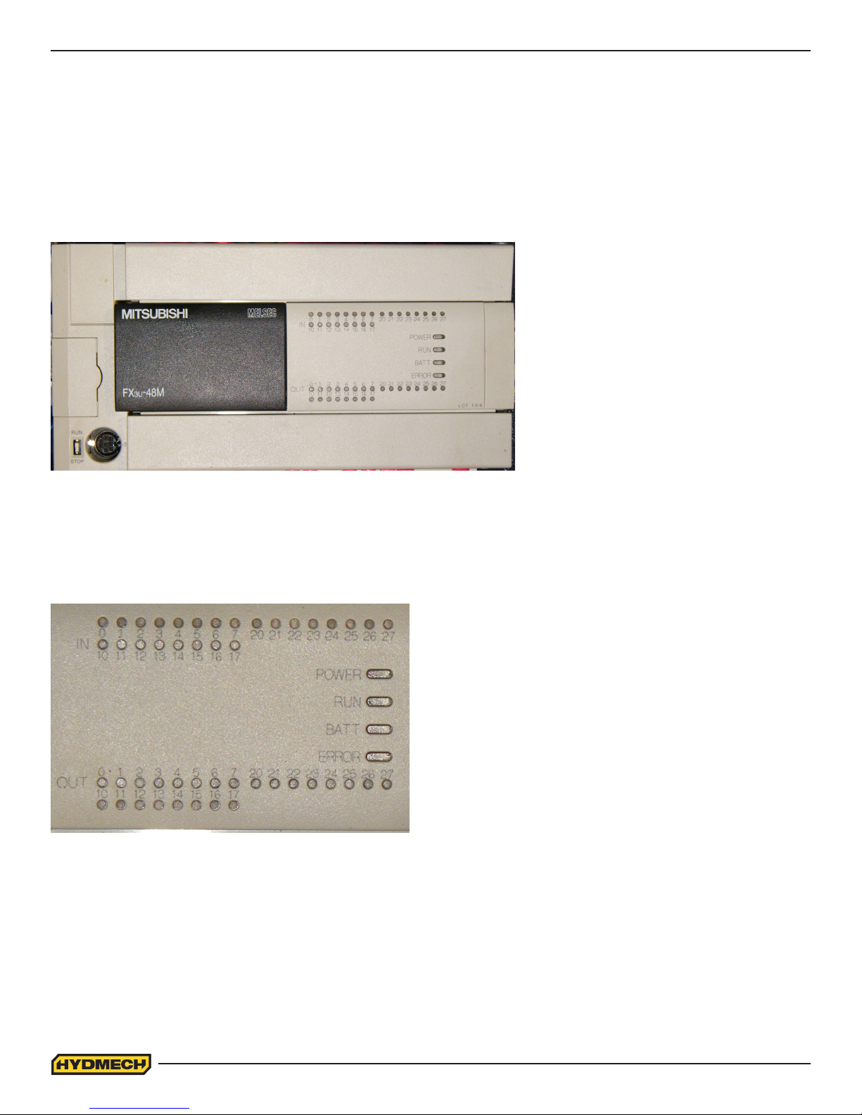
MITSUBISHI FX3U 48MR INPUTS AND OUTPUTS
PLC status indicators:
POWER On when power exists to the PLC.
RUN On when the PLC is in run mode. If not, check the run/stop switch. It should be in the run position.
BATT V6 Battery low voltage. If this LED is on, then replace the PLC battery.
ERROR: Prog E - Flashing LED indicates a program error.
Cpu -E - LED on (Solid). Indicates a CPU error.
INPUT TERMINALS
OUTPUT TERMINALS
Input and output terminal identication:
The top row of LED’S correspond to the top row of terminals and the bottom row of LED’S correspond to the bottom row of
terminals.
If LED: IN #0 is illuminated, then this corresponds to INPUT X0
If LED: OUT #17 is illuminated, then this corresponds to
OUTPUT Y17
3.18
Page 55
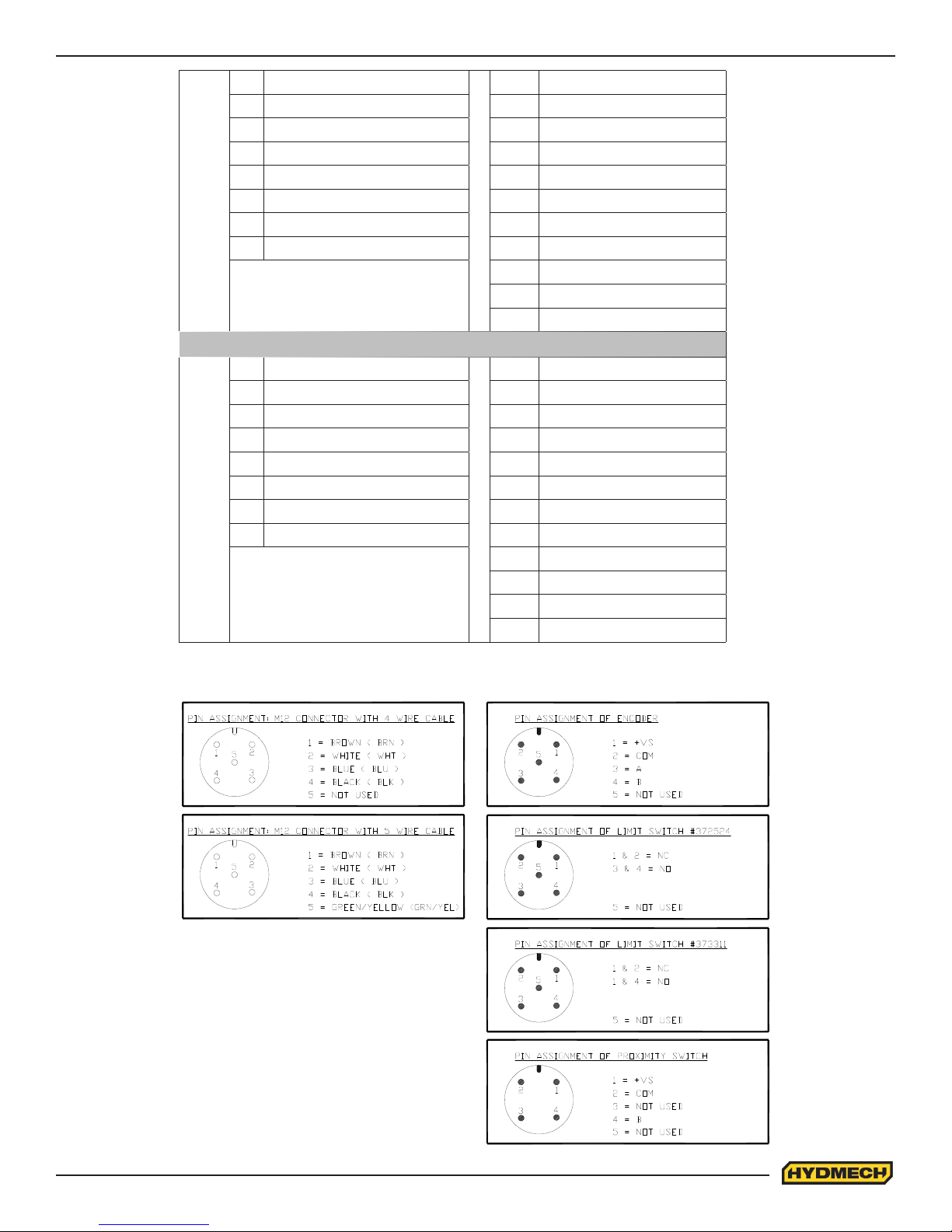
X0 Shuttle encoder, channel A X10 Shuttle vise close switch
X1 Shuttle encoder, channel B X 11 Shuttle vise open switch
X2 Blade Speed X12 Front vise close switch
X3 Feed rate encoder A X13 Front vise open switch
X4 Feed rate encoder B X14 Head raise switch
X5 Head down L/S (HDN) X15 Head lower switch
Inputs
X6 Coolant Switch X16 Blade start
X7 Coolant Switch X17 Cycle start
X20 Blade stop P/B
X21 Out of stock (option)
X22 Head up L/S (HUP)
Y0 Machine latch Y10 Front vise close (FVC)
Y1 Open Y11 Front vise open (FVO)
Y2 Open Y12 Shuttle fast (FST)
Y3 Blade run pilot light Y13 Blade motor contactor
Y4 VFD start Y14 Shuttle reverse (REV)
Y5 VFD stop / reset Y15 Shuttle forward (FWD)
Y6 Open Y16 Head raise (HUP)
Outputs
Y7 Open Y17 Head lower (HDN)
Y20 Shuttle vise close (SVC)
Y21 Shuttle vise open (SVO)
Y22 Coolant pump on / off
Y23 Cycle on pilot light
M12 PIN ASSIGNMENTS FOR I/P & O/P DEVICES
3.19
Page 56

Input/Output Terminal Information
Calibration Procedure
Length calibration may be achieved in two ways: By inputting the ACTUAL LTH or the LTH CONST parameter.
To determine the ACTUAL LTH value, the LTH CLB (length calibration) procedure must be executed.
In manual mode, position a piece of material, which is longer than the shuttle full stroke length and close the front vise.
Simultaneously press the “FWD” and “REV” buttons on the PLC to access the parameters. A password is required at this
point, which can be obtained from the Hyd·Mech Service Dept. The screen will then display as follows:
With the cursor at the shown position press the enter button. The cycle start button will start to ash and the “Enter” will
change to “On” indicating self calibration mode. Start the blade and the trim cut will be made. After the trim cut is made
the head will rise, the shuttle will retract fully in slow speed, clamp the material and come fully forward in slow speed to the
home position and make a cut. After the cut is complete “On” will change back to “Press Enter”. Measure the length of the
cut part.
Move the cursor down to the “ACTUAL LTH” and enter the length of the cut part plus the actual kerf value. Then exit the
parameters by pressing the AUTO/MAN key (the cycle start button will stop ashing). To determine if the encoder
channels are connected correctly, observe the actual length parameter for the sign only during shuttle retraction in
calibration mode. If the actual length value shows as a negative number, then the channels must be reversed and the
calibration procedure repeated.
To determine “LTH CONST” value, use this formula;
LTH CONST = ENCODER PINION CIRCUMFERENCE ÷ ENCODER RESOLUTION
Example:
For a 1” pinion diameter and 2500 PPR encoder:
LTH CONST = π(1”) ÷ 2500PPR = 0.001257
NOTE:
When rst entering the parameters screen if not running the self-calibration do not use the enter key but use the cursor
keys to scroll through the parameters.
To check length control consistency:
1. Perform test cuts of three different lengths (i.e. 1”, 12”, 20”) and measure as accurately as possible with a Vernier or
dial caliper.
2. If the measurements indicate a linear problem (measured length error increases as the programmed length
increases), the “ACTUAL LGTH” or “LTH CONST” value will have to be adjusted.
To adjust “ACTUAL LGTH” value The Length Calibration Procedure MUST be performed. This may be done with material
in the machine (cut and measure material length) or with no material in the machine (let machine complete the calibration
cycle, then enter new value).
If part length error gets longer as the programmed length increases; ACTUAL LTH value should be increased.
If part length error gets shorter as the programmed length increases; ACTUAL LTH value should be decreased
3.20
Page 57

Make small adjustments at a time (i.e. .020” - .030”) and check with test cuts.
To adjust “LTH CONST”, follow this procedure:
Cut length ÷ Programmed length x Existing “LTH CONST” = New “LTH CONST”
Example:
Cut length of 11.998”, Programmed length of 12”, Existing “LTH CONST” parameter of 0.001256.
11.988 ÷ 12.000 x 0.001256 = 0.001255
The new “LTH CONST” value of 0.001255 should be entered as the “LTH CONST” parameter and test cuts repeated.
Adjust the parameter again if necessary.
General rule:
Lowering the “LTH CONST” value = Longer shuttle travel = Longer parts.
Increasing the “LTH CONST” value = Shorter shuttle travel = Shorter parts.
HEAD HEIGHT CALIBRATION PROCEDURE
NOTE:
Head calibration may be achieved in two ways: by inputting “ACTUAL HGT” (actual height) or “HGT CONST”
(height constant) parameter.
To determine “Actual HGT” value, the “HGT CLB” (height calibration) procedure must be executed.
1. Enter the PLC parameter screen as per Length Calibration Procedure above.
2. Using the arrow cursor keys scroll down until the screen displays:
3. With the cursor on the word “ENTER”, press the enter key. The cycle start button will begin to ash, the “ENTER” will
HGT CLB PRESS
ACTUAL HGT HGT CONST
ENTER
xxxxxx
xxxxxx
change to “ON” (indicating self calibration mode) and the head will move to it’s down limit and then will move up to it’s full
upper limit.
4. Measure the distance from the vise horizontal wear strip to the blade teeth tips, and enter this value in the ACTUAL
HGT parameter. Measurement must be made along the front vise datum jaw. Input this measurement value & press the
enter key. Press the AUTO/MAN key to nish the procedure & exit the parameters screen.
NOTE:
To determine if the encoder channels are connected, observe the actual height value parameter for the sign during head
up movement while in calibration mode. If the actual height value shows as a negative number, the channels must be
reversed and the calibration procedure repeated.
To determine “HGH CONST” value, use this formula;
ACTUAL FEED RATE ÷ Displayed FEED RATE x HGT CONST = new HGT CONST.
5. Input new HGT CONST & press.
6. Press the AUTO/MAN key to exit the parameters screen.
3.21
Page 58
PLC PARAMETER DEFINITIONS & VALUES
H-18A, H-22A Parameter Definitions & Values
Description Definition Value
SPEED CONST Blade speed adjustment number.
WHEEL TARGETS Number of targets per revolution of the idler wheel. Can be toggled either 1 or 6.
HEIGHT CALIBRATION This is to be used only if calibration is required.
ACTUAL HEIGHT Actual Height Value. This value represents the head full stroke height.
HEIGHT CONSTANT Specifies linear distance of head movement in inches per one pulse of head encoder.
LENGTH CALIBRATION This is to be used only if calibration is required.
ACTUAL LENGTH Value entered after performing length calibration procedure.
LENGTH CONSTANT Specifies linear distance of shuttle movement in inches per one pulse of shuttle encoder.
ACCELERATION DISTANCE
DECELERATION DISTANCE Distance, in inches, the shuttle will travel slowly reaching before home or target position.
MINIMUM FAST DISTANCE
TARGET WINDOW Allowable +/- tolerance from programmed length.
Distance, in inches, the shuttle will travel slowly before reaching fast speed while
starting to move in either direction. (i.e. 1.000).
If the programmed length is smaller than this parameter, the shuttle will only move in
slow speed.
FRONT VICE OPEN DWELL Delay time for the opening of the fixed VISE in seconds.
SHUTTLE VICE OPEN DWELL Delay time for the opening of the shuttle VISE in seconds.
VICE CLOSE TIME Delay time for the closing of the shuttle or fixed VISE in seconds.
FEED RATE Activates feed rate display. Not active on S20A, S23A and H10 machines.
ACTUAL POSITION If this value is set to “YES,” displays shuttle vise actual position.
HOLD SHUTTLE HOME Hold shuttle VISE home and closed during cut.
BROKEN PROXIMITY SWITCH Allows user to override signal from proximity sensor in case it is broken.
MINIMUM BLADE SPEED Minimum blade speed on which the PLC will detect the that blade is running.
SPEED PROXIMITY SW. DELAY
POWER DOWN TIMER
BLADE CLEAR
TRIM CUT
OUT OF STOCK Selecting “yes” activates the out of stock option.
COOLANT
QUEUE
Delay in monitoring of the blade speed proximity sensor during acceleration of the
blade from start to desired speed set by the potentiometer.
If “0” selected, then the machine will shut down after the job is completed. Range is
from “0” to “180” minutes.
If set to “YES,” when the AUTO cycle reaches the function of head up, the shuttle
will retract the material from the blade by 1/8” before the head will move up. When
the head reaches the up position the next length of material is shuttled into position.
If “YES” selected the machine will perform a facing cut of the material at the
beginning of an automatic cycle.
When “BLD” selected, coolant flows when the blade is running. When “BLD+ DWN”
selected, coolant flows when the blade is running and head is moving down.
The queue allows the operator to run several jobs (max 5) in series. If “REPEAT” is
selected the above series will be executed the selected number of times.
3.22
Page 59

SECTION 4 - ELECTRICAL
ELECTRICAL SCHEMATICS: SEE PDF ON ATTACHED CD
4.1
Page 60

4.2
Page 61
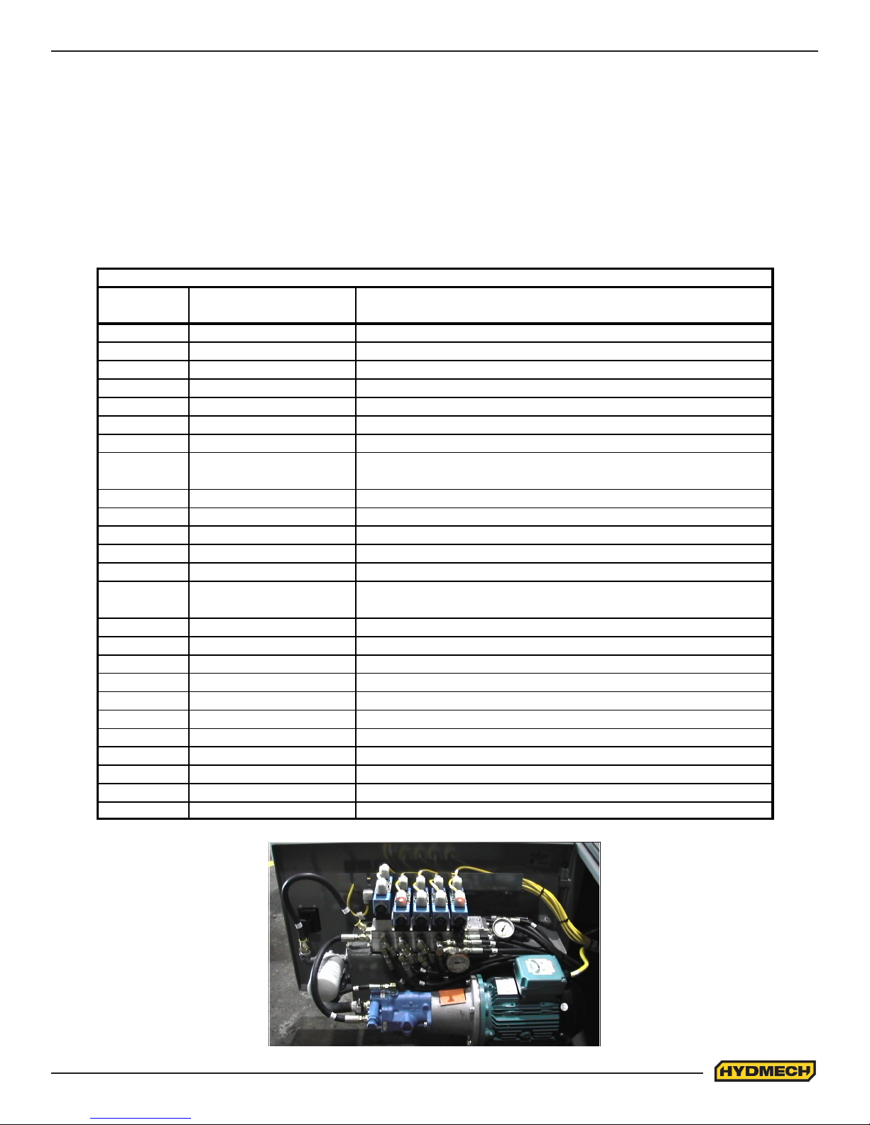
SECTION 5 - HYDRAULIC SYSTEM
R
FOR HYDRAULIC SCHEMATICS AND PLUMBING DIAGRAMS
SEE PDF ON ATTACHED CD.
The H-18/22 SV hydraulic system does not require any special work on a new machine before its start-up. The hydraulic
tank is lled with Texaco Rando HD 46 hydraulic oil and all machine functions have been tested at the factory to ensure
proper operation upon initial start-up.
HYDRAULIC COMPONENT LIST
H18ASV & H22ASV HYDRAULIC LIST
QTY (H18A)
QTY (H22A)
1 H22-C41-00A MAIN HEAD CYLINDER
1 H22-C42-00 AUX HEAD CYLINDER
1 H14-C1-00A SHUTTLE CYLINDER
1 H14-C22-00 DATUM CYLINDER
1 H22SV-C31-00C FT VISE CYLINDER
1 H22-C31-00C SHT VISE CYLINDER
(2 or 3) H22SV-C23-00 BUNDLING CYLINDER
1
1
1 MB6PA MANIFOLD BLOCK
1 DDF6-0-00FP DDF VALVE
2 363300 DOUBLE PILOT CHECK VALVE (DPCH-1)
4 363295 DIRECTIONAL VALVE (DCV3P-AB-T)
1 363290 DIRECTIONAL VALVE (DCV3P-AB-C)
1
2
1 CHB-25C CUSHION BLOCK
1 362690 CHIP AUGER MOTOR (HM-01)
1 363155 (H22 Only) PRESSURE REDUCING VALVE (PRV-2)
1 362745 HYDRAULIC PUMP (HYP-1)
1 363105 RETURN FILTER ELEMENT (SF 6520)
1 363235 PRESSURE REDUCING VALVE (PBDB OBN E21)
1 363150 PRESSURE REDUCING VALVE VVP OPTION (PRV1-10-K-6T-12 )
1 JB-02A DOUBLE JUNCTION BLOCK VVP OPTION
1 363140 HYDRAULIC CARBIDE LOCK CARTRIDGE (PRV1-10-S-0-6)
2 SPCH-1 SINGLE PILOT CHECK VALVE
1
PART NUMBER
S25-C5-00 (H18)
H22-C5-00A (H22)
363160 POPET VALVE (PV2P-A-C)
362700 (H22 Only)
BLADE TENSION CYLINDER
BLADE BRUSH MOTO
DESCRIPTION
5.1
Page 62
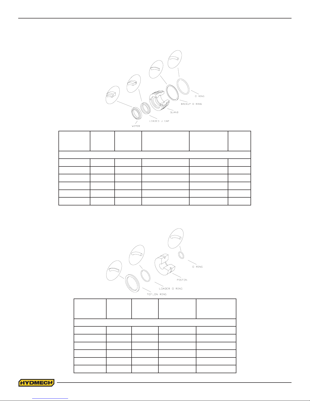
CYLINDER ASSEMBLIES
GLAND ASSEMBLIES
CYLINDER
DIAMETERE O RINGF BACKUP
2.0” 362960 362785 CS20-GL-01A 362830 363330
2.5” 362970 362790 CS25-GL-01B 362815 363335
3.0” 362985 362795 CS30-GL-01A 362815 363335
3.5” 362995 362800 CS35-GL-01A 362835 363340
4.0” 363005 362805 CS40-GL-01A 362840 363345
5.0” 363015 362810 CS50-GL-01A 362840 363345
PISTON ASSEMBLIES
O RING
G
GLAND
H
LOADED
U CAP
I
WIPER
CYLINDER
DIAMETERA TEFLON
2.0” 363035 362950 CS20-PS-01B 362905
2.5” 363040 362965 CS25-PS-01 362910
3.0” 363045 362980 CS30-PS-01 362910
3.5” 363050 362990 CS35-PS-01 362925
4.0” 363055 363000 CS40-PS-01 362940
5.0” 363060 363010 CS50-PS-01 362940
RING
B
LOADER
RING
5.2
C
PISTON
D
O-RING
Page 63

SECTION 6 - MECHANICAL ASSEMBLIES
MECHANICAL ASSEMBLY DRAWINGS & PARTS LIST: SEE PDF
ON ATTACHED CD
6.1
Page 64

6.2
Page 65

SECTION 7 - OPTIONS
OPTIONAL ASSEMBLY DRAWINGS: SEE PDF ON ATTACHED CD
7.1
Page 66

7.2
Page 67
SECTION 8 - SPECIFICATIONS
H-18 ASV BANDSAW SPECIFICATIONS
H-18A SV BANDSAW SPECIFICATIONS
Capacity
Length Control
Blade 1 1/2", (41mm) , or optional 1 1/4" ( 32mm)
Blade Tension Hydraulic
Blade Guides
Blade Wheel Dia.
Motors
Pumps
Hydraulic Tank 9.5 U.S. Gallons (36 Liters)
Round
Rectangular
Programmable up to 99 jobs, 5 in Queue
Length
Width
Thickness .050" (1.3mm) or optional (.042", 1.1mm)
VFDBlade Speed
Carbide inserts (water soluble coolant lubricated)
22" (559mm)
Blade drive 10 HP (7.5 KW)
Hydraulic pump drive
Hydraulic
Coolant
18" (457mm)
18"x 18"(457mm x 457mm)
19'-2" (5842mm)
50 - 350 sf/min (15.5 - 109 m/min)
3 HP (2.2 KW)
6 1/2 U.S. Gal. / min (25 Liters/min)
3 1/2 U.S. Gal. / min (13.5 Liters/min)
System Pressure 1000 PSI (6890 kPa)
Vise Control
Shuttle Stroke
Table Height 31" (787mm)
Control Panel Waist Height
Machine Weight
Maximum Workload 10000 lbs (4535 Kg)
Overall Dimensions
Hydraulic
0-34" (0-863mm) single stroke, multi-index capability
8500 lbs (3856 Kg)
127" (3225mm) Wide, 88" (2235mm) Long, 92.5" (2362mm) High
8.1
Page 68
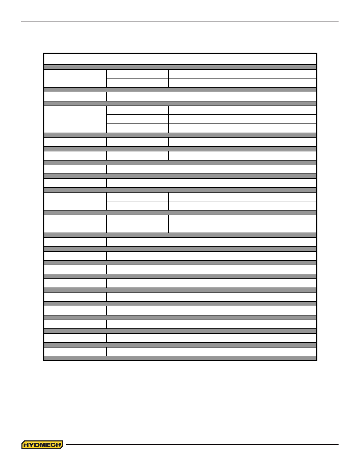
H-22 ASV BANDSAW SPECIFICATIONS
H-22A SV BANDSAW SPECIFICATIONS
Capacity
Length Control
Round
Rectangular
Programmable up to 99 jobs, 5 in Queue
Length
Blade 2"
Width
22" (558mm)
22"x 22"(558mm x 558mm)
22'-6" (6858mm)
Thickness .063" (1.6mm)
Blade Tension Hydraulic
Blade Guides
Blade Wheel Dia.
Motors
Pumps
VFDBlade Speed
Carbide inserts (water soluble coolant lubricated)
27" (685mm)
Blade drive 10 HP (7.5 KW)
Hydraulic pump drive
Hydraulic
Coolant
40 - 300 sf/min (12 - 91 m/min)
3 HP (2.2 KW)
6 1/2 U.S. Gal. / min (25 Liters/min)
3 1/2 U.S.Gal. / min (13.5 Liters/min)
Hydraulic Tank 9.5 U.S. Gallons (36 Liters)
System Pressure 1000 PSI (6890 kPa).
Vise Control
Shuttle Stroke
Hydraulic
0-34" (0-863mm) single stroke, multi-index capability
Table Height 31" (787mm)
Control Panel Waist Height
Machine Weight
12500 lbs (5670 Kg)
Maximum Workload 15000 lbs (6804 Kg)
Overall Dimensions
141" (3581mm) Wide, 88.5" (2235mm) Long, 92.5" (2362mm) High
8.2
Page 69
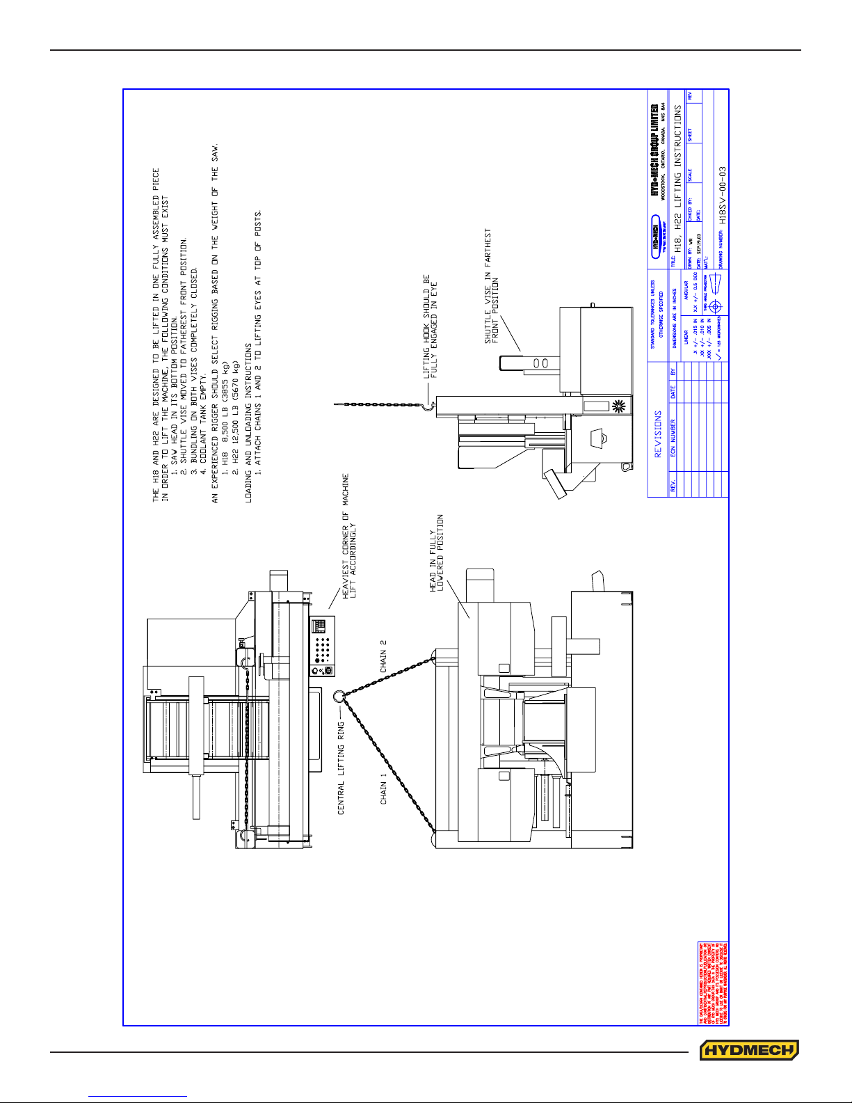
H18SV & H22SV LIFTING INSTRUCTIONS
8.3
Page 70
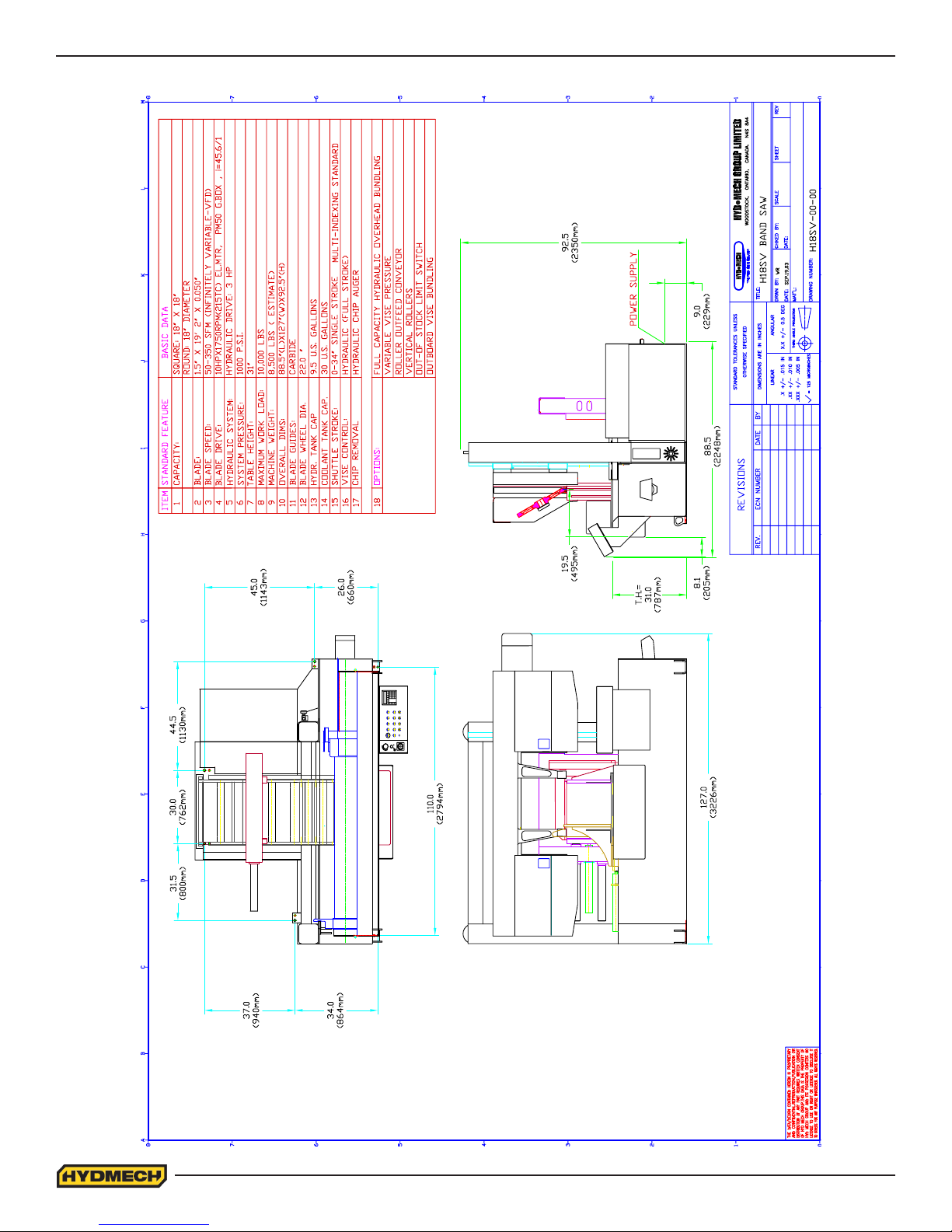
H18SV LAYOUT
8.4
Page 71
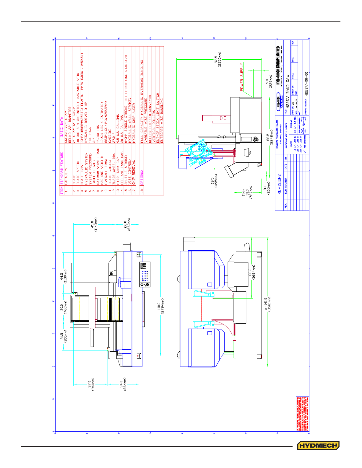
H22SV LAYOUT
8.5
Page 72

8.6
Page 73

SECTION 9 - WARRANTY
WARRANTY
Hyd·Mech Group Limited warrants parts/components on each new H-18/22 SV bandsaw to be free from failure
resulting from defective material and workmanship under proper use and service for a period of two years following the
date of shipment to the user. Hyd·Mech’s sole obligation under this warranty is limited to the repair or replacement without
charge, at Hyd·Mech’s factory, warehouse, or approved repair shop any part or parts which Hyd·Mech’s inspection shall
disclose to be defective. Return freight must be prepaid by the user.
This warranty, in its entirety, does not cover maintenance items, including but not limited to lubricating grease and oils,
lters, V-belts, saw blades, etc., nor any items therein which show signs of neglect, overloading, abuse, accident,
inadequate maintenance, or unauthorized altering.
MOTOR, GEARBOX, PUMP, ELECTRIC COMPONENTS, VALVES, HOSES, FITTINGS, and any other items used in the
manufacture of the H-18/22 SV, but not originally manufactured by Hyd·Mech are subject to the original manufacturer’s
warranty. Hyd·Mech will provide such assistance and information as is necessary and available to facilitate the user’s
claim to such other manufacturer.
Liability or obligation on the part of Hyd·Mech for damages, whether general, special or for negligence and expressly
including any incidental and consequential damages is hereby disclaimed. Hyd·Mech’s obligation to repair or replace shall
be the limit of its liability under this warranty and the sole and exclusive right and remedy of the user.
THIS WARRANTY IS EXPRESSLY IN LIEU OF ALL OTHER WARRANTIES, EXPRESSED OR IMPLIED, WRITTEN OR
ORAL, INCLUDING WITHOUT LIMITATION ANY IMPLIED WARRANTIES OF MERCHANTABILITY OR FITNESS FOR
A PARTICULAR PURPOSE.
This warranty may not be changed, altered, or modied in any way except in writing by Hyd-Mech Group Limited
HYD·MECH GROUP LIMITED
1079 Parkinson Road
P.O. BOX 1659
Woodstock, Ontario
Canada
N4S 0A9
Phone: (519) 539-6341
Fax: (519) 539-5126
Toll Free (877) 276-SAWS (7297)
E-mail, [email protected]
9.1
Page 74

9.2
 Loading...