

Hyd-Mech H-14P User Manual
H-14P
April 2005, Rev A
393303
THANK YOU,
On behalf of everyone at HYD.MECH, I would like to thank and congratulate you on your decision to purchase
a HYD.MECH band saw.
Your new machine is now ready to play a key role in increasing the efciency of your operation, helping you to
reduce cutting costs while boosting quality and productivity.
To ensure you are maximizing the power and versatility of your new HYD.MECH band saw, please take the
time to familiarize yourself and your employees with the correct operation and maintenance procedures as
outlined in this manual.
We sincerely appreciate the condence you have demonstrated in purchasing our product and look forward to
building a long and mutually benecial relationship.
Thank-you.
HYD.MECH GROUP LIMITED
P.O. BOX 1030, 1079 Parkinson Road
Woodstock, Ontario Canada, N4S 8A4
Phone: (519) 539-6341
Service 1-877-237-0914
Sales 1-877-276-SAWS(7297)
Fax (519) 539-5126
e-mail, info@hydmech.com
1


TABLE OF CONTENTS
SECTION 0 - SAFETY INSTRUCTIONS
SUMMARY ..................................................................................................................................................................0.1
FOREWORD ...............................................................................................................................................................0.2
RESPONSIBILITIES OF THE OWNER .......................................................................................................................0.5
RESPONSIBILITIES OF THE OPERATOR AND MAINTENANCE PERSONNEL ......................................................0.6
SECTION 1 – INSTALLATION
SAFETY PRECAUTIONS ............................................................................................................................................1.1
LIFTING AND SHIPPING ............................................................................................................................................1.2
FOUNDATION LEVELING AND ANCHORING ........................................................................................................... 1.2
EARTH GROUNDING PROCEDURE .........................................................................................................................1.2
WIRING CONNECTIONS ............................................................................................................................................1.3
HYDRAULIC OIL AND CUTTING FLUID ....................................................................................................................1.3
SECTION 2 - OPERATION INSTRUCTIONS
BLADE BASICS...........................................................................................................................................................2.1
VARIABLE SPEED CONTROL....................................................................................................................................2.1
SECTION 2 - OPERATION INSTRUCTIONS
THE CONTROL CONSOLE ........................................................................................................................................2.2
PLC CONTROL PANEL ...............................................................................................................................................2.4
MANUAL MODE OPERATION ....................................................................................................................................2.6
AUTOMATIC OPERATION ..........................................................................................................................................2.6
COOLANT FLOW ........................................................................................................................................................ 2.7
KERF CORRECTION .................................................................................................................................................. 2.7
HYDRAULIC FEED CONTROL ...................................................................................................................................2.8
CUTTING PARAMETERS CHART .............................................................................................................................. 2.8
VARIABLE VISE PRESSURE (OPTION) .................................................................................................................... 2.13
BUNDLING OPERATION (OPTION) ...........................................................................................................................2.13
SECTION 3 - MAINTENANCE & TROUBLESHOOTING
BLADE CHANGING PROCEDURE ............................................................................................................................3.1
BLADE TRACKING AND ADJUSTMENT .................................................................................................................... 3.1
BLADE GUIDE ADJUSTMENT ...................................................................................................................................3.3
BLADE BRUSH ADJUSTMENT ..................................................................................................................................3.3
CAM FOLLOWER ADJUSTMENT ..............................................................................................................................3.3
LUBRICATION ............................................................................................................................................................. 3.3
HYDRAULIC MAINTENANCE .....................................................................................................................................3.4
CLEANLINESS ............................................................................................................................................................ 3.5
TROUBLESHOOTING ................................................................................................................................................3.6
PROGRAMMABLE LOGIC CONTROL, MITSUBISHI 100 .........................................................................................3.7
PLC 100 TROUBLESHOOTING .................................................................................................................................3.9
SECTION 4 - ELECTRICAL SYSTEM
GENERAL INFORMATION ..........................................................................................................................................4.1
INITIAL HOOKUP ........................................................................................................................................................ 4.1
H-14P ELECTRICAL SCHEMATICS 208-240 VAC .....................................................................................................4.6
H-14P ELECTRICAL SCHEMATICS 480-575 VAC .....................................................................................................4.14
SECTION 5 - HYDRAULIC SYSTEM
GLAND ASSEMBLIES.................................................................................................................................................5.2
PISTON ASSEMBLIES ................................................................................................................................................ 5.2
HYDRAULIC SCHEMATIC ..........................................................................................................................................5.3
HYDRAULIC PLUMBING DIAGRAM ..........................................................................................................................5.4
SECTION 6 - MECHANICAL
BLADE BRUSH ASSEMBLY .......................................................................................................................................6.1
1

GUIDE ARM ASSEMBLY ............................................................................................................................................6.2
HYDRAULIC CARBIDE GUIDE ASSEMBLY ..............................................................................................................6.3
BLADE TENSIONER ASSEMBLY ............................................................................................................................... 6.4
HYDRAULIC TANK ASSEMBLY ..................................................................................................................................6.5
HYDRAULIC PUMP ASSEMBLY.................................................................................................................................6.6
CHIP AUGER ASSEMBLY...........................................................................................................................................6.7
FRONT VISE ASSEMBLY ...........................................................................................................................................6.8
CONVEYOR ASSEMBLY ............................................................................................................................................6.10
BONFIGLIOLI A412 GEARBOX ASSEMBLY .............................................................................................................. 6.12
REYNOLDS PM40 GEARBOX ASSEMBLY ................................................................................................................6.14
SECTION 7 - OPTIONAL EQUIPMENT
BUNDLING ASSEMBLY ..............................................................................................................................................7.1
VERTICAL ROLLERS .................................................................................................................................................7.2
OUT OF STOCK ASSEMBLY ......................................................................................................................................7.3
VARIABLE VISE PRESSURE ..................................................................................................................................... 7.3
SECTION 8 - SPECIFICATIONS
H-14P LAYOUT DRAWING .........................................................................................................................................8.2
SECTION 9 - WARRANTY
WARRANTY ................................................................................................................................................................9.1
PLC PARAMETERS .................................................................................................................................................... 9.2
2

SECTION 0 - SAFETY INSTRUCTIONS
SUMMARY
All persons operating this machine must have read and understood all of the following sections of this Manual:
Section 0 SAFETY
Section 2 OPERATING INSTRUCTIONS
However, as a memory aid, the following is a summary of the Safety Section.
Put Safety First
Mandatory Information – What operators and maintenance people must have read and understood.
Signatures – Everyone involved with this machine must sign to conrm they have read and understood mandatory infor-
mation.
Basic Rules – only use this machine when
• it is in good working order
• all safety equipment is in place and functional
• operations are in compliance with this manual
• materials are within designed specications and are non-hazardous
Owner is responsible to
• keep Manual accessible at the machine
• ensure only reliable, fully trained personnel work with the machine
• clearly dene responsibilities of all personnel working with the machine
• keep the machine in good working order
Operator and Maintenance Personnel are responsible to:
• keep all safety equipment in order, check its function at the beginning of each shift, and report any shortcomings
• shut-down machine and report any faults or malfunctions which could impair safety
• understand and obey safety hazard labels
• not to wear un-restrained long hair, loose clothing or jewellery
• wear all required personal protective equipment
• not to wear gloves within 24 inches of moving blade
• maintain a clean working area and machine
• always use Lock-out when performing maintenance or repairs.
0.1

FOREWORD
Put Safety First!
This Safety Section contains important information to help you work safely with your machine and describes the dangers
inherent in our machines. Some of these dangers are obvious, while others are less evident.
It really is important to PUT SAFETY FIRST. Make it a habit to consider the hazards associated with any action BEFORE
you do it. If you feel any uncertainty, stop and nd a safer approach to the action. If you’re still uncertain, ask for advice
from your supervisor.
The SAFETY FIRST approach is particularly necessary when you do something new, or different, and most people instinctively recognize this, although impatience may still cause them to take unnecessary risks.
Danger also lurks in the routine task that we have done over and over. Here, familiarity, boredom, or tiredness may lull us
into unthinking, automatic repetition. Be alert for this, and when you feel it happening, stop and take stock of your situation. Review the safety hazards associated with what you are doing. That should get your brain working again.
Certainly production is important, but if you think you’re too busy to put safety rst, think how much production you’ll lose if
you get hurt.
You owe it to yourself, your family, and your co-workers to PUT SAFETY FIRST.
Mandatory Information
All persons operating this machine must have read and understood all of the following sections of this Manual:
Section 0 SAFETY
Section 2 OPERATING INSTRUCTIONS
Personnel involved in installation and maintenance of the machine must have read and understood all sections of the
manual
Persons who have difculty reading, or for whom English is not their rst language, must receive particularly thorough
instruction.
0.2

Signatures
Everyone involved in operation of this machine must sign below to conrm that:
I have read and understood all parts of Section 0 – Safety, and Section 2 – Operating Instructions.
Name Date Signature
Everyone involved in the installation, inspection, maintenance, and repair of this machine must sign below to conrm that:
I have read and understood all parts of this Operation and Maintenance Manual.
Name Date Signature
BASIC RULES
Intended Use
Our machines are designed and built in line with the state of the art, and specically in accordance with
American National Standards Institute Standard B11.10 Safety Requirements for Metal Sawing Machines.
However, all machines may endanger the safety of their users and/or third parties, and be damaged,
or damage other property, if they are operated incorrectly, used beyond their specied capacity, or for
purposes other than those specied in this Manual.
0.3

Exclusion of Misuse
Misuse includes, for example:
Sawing hazardous materials such as magnesium or lead
Sawing work pieces which exceed the maximum workload appearing in the Specications
Operating the machine without all original safety equipment and guards
Liability
The machine may only be operated:
when it is in good working order, and
when the operator has read and understood the Safety and Operating Instructions Sections of the Manual, and
when all operations and procedures are in compliance with this Manual.
Hyd-Mech Group cannot accept any liability for personal injury or property damage due to operator errors
or non-compliance with the Safety and Operating Instructions contained in this Manual.
0.4

RESPONSIBILITIES OF THE OWNER
Organization of work
This Operation and Maintenance Manual must always be kept near the machine so that it is accessible to
all concerned.
The general, statutory and other legal regulations on accident prevention and environmental protection
must also be observed, in addition to the Manual material. The operators and maintenance personnel
must be instructed accordingly. This obligation also includes the handling of dangerous substances and
the provision and use of personal protective equipment.
Choice and qualication of personnel
Ensure that work on the machine is only carried out by reliable persons who have been appropriately
trained for such work.
Training
Everyone working on or with the machine must be duly trained with regard to the correct use of the machine, the correct use of safety equipment, the foreseeable dangers that may arise during operation of the
machine, and the safety precautions to be taken.
In addition, the personnel must be instructed to check all safety devices at regular intervals.
Dene responsibilities
Clearly dene exactly who is responsible for operating, setting-up, servicing and repairing the machine.
Dene the responsibilities of the machine operator and authorize him to refuse any instructions by third
parties if they run contrary to the machine’s safety.
Persons being trained on the machine may only work on or with the machine under the constant supervision of an experienced operator. Observe the minimum age limits required by law.
0.5

Condition of Machine and Workplace
Ensure that the machine and its safety equipment is kept in good working order.
Ensure that the work area is well lit, and protected from the elements, such as rain, snow, abrasive dust,
and extremes of temperature.
Ensure that the machine is installed with sufcient clearance around it for the safe loading and unloading
of work pieces.
RESPONSIBILITIES OF THE OPERATOR AND MAINTENANCE PERSONNEL
Safety equipment
All machines are delivered with safety equipment that must not be removed or bypassed during operation.
The correct functioning of safety equipment on the machine must be checked:
• at the start of every shift.
• after maintenance and repair work
• when starting for the rst time, and after prolonged shutdowns
Emergency Stop Button ( E-Stops)
Always be aware of the location of the Emergency Stop Button(s). Do not allow material or objects to
block your access to an Emergency Stop.
Damage
If any changes capable of impairing safety are observed in the machine or its operation, such as damage,
malfunctions, or irregularities, then appropriate steps must be taken immediately, the machine switched
off, locked-out, and the fault reported to the responsible person.
Safe operation
The machine may only be operated when in good working order and when all protective equipment is in
place and operational.
Keep a safe distance from all moving parts – especially the blade and vises
Stock should not be loaded onto the saw if the blade is running
Long and heavy stock should always be properly supported in front of and behind the saw.
Faults
The machine must be switched off and locked-out before starting to remedy any faults.
Safety hazard labels
Safety hazard labels, and other instructional labels on the machine must be observed. They must be
clearly visible and legible at all times. If they become damaged they must be replaced.
Clothing, jewellery, protective equipment
Personnel operating or working on the machine must not wear un-restrained long hair, loose-
0.6

tting clothes and dangling jewellery.
When operating or working on the machine, always wear suitable, ofcially tested personal pro-
tective equipment such as safety glasses and safety boots and any other equipment required by
plant regulations.
Gloves
Experience has shown that careless use of gloves around machinery is a major factor in serious
hand injuries.
Gloves should not be worn when operating or adjusting the machine, except:
Wear protective gloves when handling bandsaw blades at blade changes.
Gloves may be worn when handling work pieces, only if the machine is in Manual Mode
and the bandsaw blade is not running.
If the machine is running in Auto Mode, and only if the cut parts are greater than 24
inches long, it may be possible to safely wear gloves for handling the cut parts, but the
wearer of the gloves must never put his hands near the blade for any reason. If the cut
parts are less than 24 inches long, it is required to arrange their automatic ow into a
parts bucket or other suitable arrangement to avoid the necessity to pick them off the
machine by hand.
Hearing protection
Workplace
A clear working area without any obstructions is essential for safe operation of the machine. The oor
must be level and clean, without any build-up of chips, off-cuts, coolant, or hydraulic oil.
The workplace must be well lit, and protected from the elements, such as rain, snow, abrasive dust, and
extremes of temperature
Nothing may ever be placed on, or leaned against the machine, with the obvious exception of the work
piece on the table and conveyor of the machine.
Ear protection must be worn whenever necessary.
The level and duration of noise emission requiring hearing protection depends upon the national
regulations in the country in which the machine is being used.
The actual level of noise emission by band sawing machines depends upon work piece size,
shape and material, blade type, blade speed and feed rate.
The only practical course of action is to measure the actual noise emission levels for the type
of work that is typically done. With reference to national standards, decide upon the necessary
hearing protection required.
In the absence of such measurements, it is advisable for anyone exposed to long periods of
moderate to loud noise to wear hearing protection. It is important to understand that hearing loss
is gradual and easily goes un-noticed until it is serious and irreversible.
Master Disconnect
Lock-out the machine before undertaking any maintenance or repair work on it. ‘Lock-out’ refers switching
off the master electrical disconnect switch, and locking it out so that it cannot be switched on again
without authorization.
On Hyd-Mech machines the Master Disconnect Switch will be of one of three types:
• Rotary switch mounted in electrical control cabinet door and inter-locked with door
0.7

• Lever switch mounted in separate box mounted on the machine
• Supply disconnect switch supplied by user at installation and usually wall-mounted within sight of
the machine, depending upon local regulations.
In almost all jurisdictions, it is required that owners of industrial equipment establish and post lock-out procedures. Know and use the lock-out procedures of your company or organization.
Residual Risks
The machine is still not completely de-energized if an electrical cabinet door type switch is
locked-out.
The line side of the disconnect switch itself remains energized.
Variable speed blade drives store dangerous voltage in their capacitors, and this requires time to
dissipate. After locking out power, wait 3 minutes before beginning to work on machine electrical
circuits.
If compressed air is supplied to the machine to power a mist lubrication system or other devices,
it should be disconnected, and any stored air pressure released before working on the machine.
The weight of individual machine components represents stored potential energy that can be
released if they fall when disconnected. Secure these components with adequate hoisting gear
before disassembly.
0.8

SECTION 1 – INSTALLATION
Upon delivery of you r new H-14P saw, it is imperative that a thorough inspection be undertaken to check for any damage
that could have been sustained during shipping. Special attention should be paid to the electrical and hydraulic systems to
check for damaged cords and hoses or for uid leaks. In the event of damage caused during shipping, contact your carrier
to le a damage claim.
SAFETY PRECAUTIONS
The H-14P has been designed to give years of reliable service. It is essential that operators be alerted to the safe operation of this saw, and the practices to avoid that could lead to injury. The following safety rules are at a minimum for the
safe installation, operation and maintenance of the saw. Take every precaution for the protection of operators and maintenance personnel.
• POWER HOOK-UPS AND REPAIRS SHOULD BE ATTEMPTED ONLY BY QUALIFIED TRADESMEN.
• THE SAW SHOULD BE LOCATED IN AN AREA WITH SUFFICIENT ROOM TO SAFELY LOAD STOCK INTO
THE SAW. SECURE THE SAW TO THE FLOOR.
• THE AREA AROUND THE SAW SHOULD BE MAINTAINED IN A CLEAN AND TIDY CONDITION TO AVOID
OBSTACLES OPERATORS COULD TRIP OVER.
• THE H-14P SHOULD ONLY BE OPERATED ACCORDING TO THE SPECIFICATIONS OF THE SAW. AVOID
UNSAFE USAGE PRACTICES.
OPERATOR:
• THE SAW SHOULD NEVER BE OPERATED UNLESS ALL GUARDS AND DOORS ARE IN PLACE AND
CLOSED.
• KEEP A SAFE DISTANCE FROM ALL MOVING PARTS ESPECIALLY THE BLADE AND VISES.
• LOOSE CLOTHING AND GLOVES SHOULD NEVER BE WORN WHILE OPERATING THE SAW. COVER LONG
HAIR.
• STOCK SHOULD NOT BE LOADED ONTO THE SAW IF THE BLADE IS RUNNING.
• LONG AND HEAVY STOCK SHOULD ALWAYS BE PROPERLY SUPPORTED IN FRONT OF AND BEHIND THE
SAW.
• NEVER ATTEMPT TO DISLODGE OR MOVE STOCK WHILE THE BLADE IS MOVING. TAKE THE TIME TO
STOP THE SAW BLADE, REMOVE OBSTRUCTIONS AND RESTART THE BLADE.
• WEAR EYE PROTECTION
• MAINTAIN PROPER ADJUSTMENT OF THE BLADE TENSION, BLADE GUIDES, AND THRUST BEARINGS.
No modications to the machine are permitted without prior approval from HYD·MECH. Any modications should only be
undertaken by trained personnel.
1.1
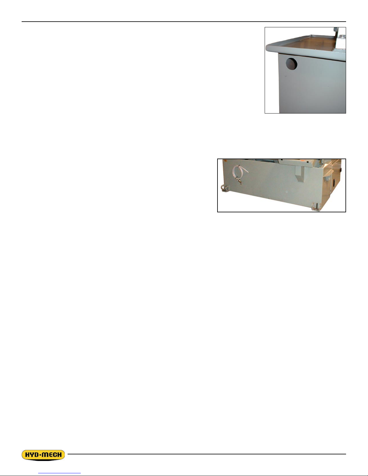
LIFTING AND SHIPPING
This machine is designed to be lifted in one fully assembled piece. In order to lift the machine it needs to be in the following condition:
• Saw head in its bottom position.
• Coolant tank emptied.
The H-14P may be lifted from the front with a forklift which has a capacity of 5000 lbs and
a fork length of 72” (1830mm).
Lifting chains may be used as an alternative if used in the manner described below:
Lifting chains are fastened to 1 - 2¼” diameter steel bar inserted in the base and 2 lugs at the front base.
FOUNDATION LEVELING AND ANCHORING
Machine location should be carefully selected. A at concrete oor area
should be chosen. It should have enough free space surrounding the
machine to enable free access for safe operation and maintenance.
The machine should be leveled in both directions, i.e. along and across
its infeed conveyor especially when machine is to be inserted into a
larger conveyor system. Six leveling screws are provided, one in each
corner of the machine base as shown below. Steel plates are to be
placed under each screw to prevent their sinking into the concrete oor.
In cases when the machine is to be anchored permanently, anchoring
holes are provided. They are located next to the leveling screws.
NOTE:
In some cases leveling the saw infeed and auxiliary conveyors with a slight slope towards the blade is recommended. This
will prevent coolant from running down the raw stock. (This is especially true when cutting tubing or bundles)
GENERAL INFORMATION
This machine has been built to the customers requirements, however, if any voltage changes are required, please consult
Hyd·Mech service department before implementing any changes.
NOTE:
1. The PLC is equipped with a lithium battery to keep the program stored while the power is shut down. The battery
will need to be replaced every 3 to 5 years, depending on usage. A visual warning will be displayed on the inter-
face when the battery drains to a certain level. Batteries can be purchased through your Hyd·Mech Distributor.
2. If the machine is equipped with an inverter, do not turn the disconnect on for 3 three minutes after disconnect has
been shut off. Cycling power sooner than 3 minuets will result in damage to the Variable Frequency Drive.
EARTH GROUNDING PROCEDURE
1. Customer to provide and install a ground rod approx. 60 (15mm) diameter, copper clad steel, to be driven no less
than 8’ (2.5m) into the ground, no more than 10’ (3m) away from control enclosure.
2. Ground rod to be connected to customer’s in plant ground system. This connection shall be made directly at the
ground rod (If applicable).
3. It is desirable that the overall resistance to ground measured at the ground rod does not exceed 3 ohms. Customer is advised to consult local power company for further information on grounding.
1.2

4. Ground rod to be connected to ground terminal in control enclosure using insulated 8-gauge stranded copper
wire.
5. An additional point to check is ensuring continuity of ground within control enclosure. Start with main power
entrance ground terminal where internal ground conductors should originate and connect to, DIN terminal strip,
control transformer and the lid of control enclosure. Also PLC and Interface units should have their own ground
conductors connected to one of the main ground terminals.
6. Properly functioning ground system will;
• Provide safety for personnel.
• Ensure correct operation of electrical/electronic devices.
• Prevent damage to electrical/electronic apparatus.
• Help dissipate lightning strokes.
• Divert stray radio frequency (RF) energy from electronic/control equipment.
WIRING CONNECTIONS
After the machine is leveled and anchored the necessary power hook-up needs to be performed.
In order to provide a safe operation as well as to prevent potential damage to the machine, only qualied personnel
should be allowed to do the work.
The rst two areas that need to be checked are:
• There are no signs of shipping damage to electrical conduits, cords or hydraulic hoses.
• Hydraulic oil level is between the upper and lower lines on the level gauge.
As supplied, the machine is set to run on the three phase voltage as indicated on the serial plate and voltage label.
Power connection to the machine is made to the main disconnect box with the Ll, L2,L3 and Ground terminals. The disconnect box is located at the drive side of the machine.
During the initial hook-up it is very important to check that the phase order is correct. This is indicated by the hydraulic
pressure gauge registering a pressure rise and the blade running in a counterclockwise direction. If the hydraulics do not
register an immediate pressure rise,
- shut the hydraulics off and change the phase order.
HYDRAULIC OIL AND CUTTING FLUID
As shipped the saw oil tank is lled with Arco - Duro AW46 hydraulic oil. If you want to change the hydraulic oil or the
brand of oil, see HYDRAULIC MAINTENANCE.
No cutting uid is supplied with the machine. There are two types of coolant available:
• oil based; dilute in 1:10 ratio (one part of concentrated coolant and 10 parts of water)
• -synthetic; dilute as recommended by manufacturer.
1.3


SECTION 2 - OPERATION INSTRUCTIONS
This section has been prepared to give the operator the ability to set up the saw for most cutting situations. The saw is
equipped with variable blade speed control and hydraulic feed control, as well as an extensive door chart to guide the
operator to the correct setting of these controls.
BLADE BASICS
Technology is rapidly changing all aspects of production machining. Metal cutoff is no exception. The advances made
in the bandsaw blade industry have denitely brought down the cost per cut, despite the three fold higher price of high
technology blades. Variable pitch, bi-metal blades (like the 4/6 or 3/4 bi-metal blade supplied with the M-16/20) last much
longer, cut faster, and more accurately than conventional carbon steel blades. In order to take advantage of the superiority
of bi-metal blades, it is critical to properly “break-in” a new blade. This is accomplished by taking two or three cuts through
solid four or ve inch diameter mild steel at an extremely slow feed rate. (It is also advisable to utilize a slow blade speed.)
These two or three slow cuts sufciently lap (polish) the new blade so that it does not snag the material being cut. Proper
break-in will alleviate blade vibration; improve surface nish, accuracy, and blade life.
After “break-in”, the following six points must be closely monitored to ensure long blade life:
1. Proper blade tension should be maintained. (See Section 3, Blade Changing)
2. Generous coolant application is essential with most materials. A high quality and well mixed coolant will extend
blade life, and also increase cutting rate and quality. On those materials where coolant is undesirable for cutting,
a slight coolant ow or periodic oiling of the blade is necessary to prevent the blade from being scored by the
carbide guides.
3. The stock being cut must be securely clamped in the vises.
4. The proper feed force should be chosen.
5. The proper blade speed must be selected.
6. The proper feed rate must be applied.
VARIABLE SPEED CONTROL
Blade speed can be adjusted innitely between 50 to 350 SFM (Surface Feet/Minute) (15.3 to 107 meters/min). The blade
speed is controlled with dial on the control panel.
Blade speed adjuster.
2.1
THE CONTROL CONSOLE
START-UP
The H-14/18/22 control console has been designed to simplify the operation of the saw, to give the operator the ability to
stop any function at any time, and to be able to control all the functions remotely. We cannot overstress the importance of
familiarizing yourself with the controls of the H-14/18/22 prior to starting the machine.
NOTES:
1. ALL SWITCHES MUST BE IN THE CENTER NEUTRAL POSITION TO START THE MACHINE!
2. WHEN STARTING THE MACHINE FOR THE FIRST TIME MAKE SURE THAT BLADE IS MOVING IN A
COUNTERCLOCKWISE DIRECTION, AND THAT THE HYDRAULIC PRESSURE IS 700 PSI (H-14),1000
PSI (H-18) AND 1100 PSI (H-22). IF THERE IS NO IMMEDIATE PRESSURE, SHUT THE SAW DOWN AND
CHANGE THE PHASE ORDER AS STATED IN SECTION 1 .
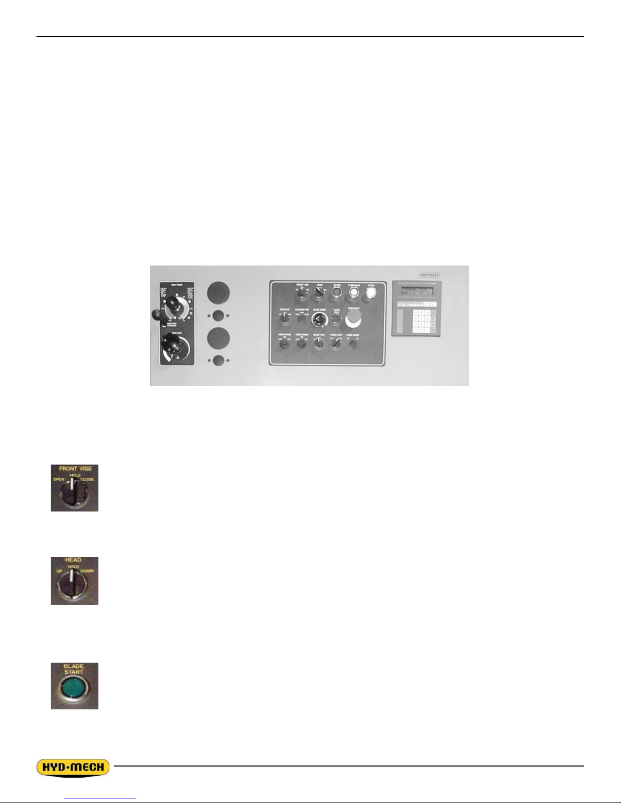
TOP ROW
Operator Control Console
FRONT VISE - This switch has three positions, OPEN, HOLD and CLOSE. With the switch held in
the OPEN position the vise will open all the way or until the switch is released. With
the switch in the HOLD position, the vise will stay where it is and will not move freely
although it will not resist a large force indenitely without creeping. In CLOSE, the
vise will close all the way, or until it encounters enough resistance to stop it.
HEAD CONTROL - This switch has three positions: UP, HOLD and DOWN. The switch is inactive unless
the PLC is in manual mode. In the UP position, the head will rise until it trips the head
up limit which is adjustable via the PLC. In the HOLD position the head will stay still.
In the DOWN position the head will descend until it reaches the bottom of the stroke.
The speed of descent is controlled by the Head Feed and Head Force Limit controls.
BLADE START - The blade can be started only when the hydraulics are running in either manual or
auto mode.
NOTE: In automatic Mode the head will not descend until the blade has been started, which the PLC will
prompt the operator to do so.
2.2

CENTER ROW
HYDRAULIC START - To start the hydraulic system, the switches for the head and both vises
must be in the “NEUTRAL” position. The “HYDRAULIC START” button must be depressed and held in momentarily until the PLC display
becomes active.
CYCLE START / PAUSE - This button starts the cutting cycles and will stay illuminated white until
the cycles are completed. The PLC control system will prompt you
to start the blade if it is not running. The machine will then begin the
automatic cycle until completed when it will shut itself off. The current
cycle can be PAUSED by pressing this button at any time during a
cycle and restarted by pressing it again.
COOLANT - This switch has three positions, ON, OFF, and AUTO. In the ON position, the
coolant system will operate when there is power to the machine, this allows
using the wash gun to clean the machine. In the OFF position, the coolant
system is inactive. In the AUTO position the coolant system will only run when
the head is descending. This minimizes coolant carry over on the stock.
BOTTOM ROW
BLADE SPEED -
This dial will increase or decrease the speed at any time while the blade is
running.
BLADE STOP -
Stops the blade. If the blade is stopped during a cycle, the cycle will continue
but will not let the head descend until the blade is started.
STOP - This mushroom button stops the blade and hydraulic motors. Both vises will
hold their position but, pressure will begin to fall off. Long pieces of work
should always be supported so they will not become loose over time and fall
while the machine is shut down.
WORK LAMP -
This switch has two positions, OFF and ON.
LASER GUIDE - This option switch has two positions, OFF and ON.
2.3

MITSUBISHI PLC CONTROL SYSTEM
NOTE:
This instruction manual is applicable to the M16P, M20P, H14P to H32P machines equipped with a Mitsubishi PLC, c/w
feed rate display, manufactured with serial numbers ending with or higher than _ _ _ _ 0899.
OPERATION OVERVIEW
The PLC is a programmable logic controller which allows the operator to run the machine in both manual and automatic
modes.
In manual mode, all functions can be operated by using a combination of selector switches on the control console and the
PLC function buttons.
In automatic mode, the machine will cycle for one cut and be ready for the next cut when nished.
NOTE:
If an emergency situation arises during any operations, use the large red mushroom “EMERGENCY STOP” button located
on the control panel to shut down the machine.
ACTIVATING THE PLC
Position the head and vise switches to the NEUTRAL (center) positions. If either of these switches are not in the NEUTRAL position, the hydraulics will not start. The PLC control will become active when the HYDRAULIC START button is
depressed and “held in” momentarily. First, the PLC’s current revision number will be shown on the display window. The
AUTO/MAN indicator light will be off and all MANUAL controls are enabled.
PLC CONTROL PANEL
DISPLAY WINDOW
PLC FUNCTION BUTTONS
CURSOR BUTTONS
NUMERIC KEYPAD
CLEAR DATA KEY
AT CURSOR POSTION
INACTIVE KEYS
DATA ENTRY KEY
2.4

FUNCTION BUTTON DESCRIPTIONS
If a red indicator light above a function button is illuminated, it means that the function printed in red at the top of the button is enabled. No light indicates the function printed in black at the bottom of the function button is enabled. The following
are the function keys for AUTO and MAN modes:
AUTO MODE No function.
HOME
MAN MODE If pressed and held in for a few seconds, the HEAD HOME cycle will be initiated.
NOTE: Before using AUTO MODE, it is necessary to “HOME THE HEAD”. This must
be repeated any time the hydraulic system has been shut down so the machine
knows where its HOME position is. While the head fast approach can be used during this operation, it is recommended the lever be released so that the head meets
it home position gently.
AUTO
MAN
P
METRIC
INCH
AUTO / MAN MODE This button will toggle between MAN and AUTO modes. Auto mode cannot be ac-
cessed unless the vise is closed.
Also used to stop an automatic job in progress by switching to MANUAL mode.
AUTO MODE No function, both keys.
MAN MODE Used to access the PARAMETERS. When these two keys are pressed simultaneously,
the display will change to the password (# obtained from Hyd·Mech) screen before the
parameters are displayed. The vise must be closed and the PLC in “INCH” to access the
parameters. To exit the “PASSWORD” back to “MAN”, press or To exit the
AUTO
MAN
METRIC
INCH
“PARAMAETERS” mode, press at any time.
NOTE: Consult the Hyd-Mech Service department before entering the parameters.
AUTO MODE No function.
MAN MODE No function.
AUTO / MAN MODE This button toggles to allow values to be displayed either in millimeters or inches
and the blade speed in either surface feet per minute or meters per minute. It
2.5

MANUAL MODE OPERATION
In MAN mode, the PLC allows the operator to make a single cut. To accomplish this, take the following steps.
1. Open the vise.
2. Raise the head to so that the blade is above the material to be cut.
3. Load the material and position it for a cut, close the vise.
4. Set the feed rate (displayed) and feed force (not displayed) as described in Section 2B.
5. Start the blade and set the desired speed (displayed).
6. Turn on and adjust the coolant as required.
7. Turn the head switch to DOWN and the cut will begin.
8. When the cut is completed, raise the head.
9. To cut another piece, repeat steps 2 through 8.
NOTES:
• To “PAUSE” the cut, turn the HEAD switch to “HOLD” or “UP”.
• The blade speed, feed force, feed rate and guide arm can all be adjusted during a cut if necessary.
AUTOMATIC OPERATION
NOTE: Before entering AUTO mode, the head should be “HOMED” as the operator will be prompted to do so when the
“AUTO MODE” is accessed. See function button description for
1. Open the vise.
2. Raise the head so that the blade is well above the material to be cut. This should be done to minimize the possibility of damage to the blade while loading material.
3. Load the material and position it for a cut , close the vise.
4. Set the feed rate (displayed) and feed force (not displayed) as described in Section 2B.
5. If the blade speed must be adjusted, start the blade and set the desired speed (displayed).
6. Press the key, the blade will stop if it is running, and the display will change to that shown below.
AUTO
MAN
HOME
When the AUTO/MAN button is pressed, the red indicator light above it will come on, and the blade will stop if it
has been running and all manual functions will be disabled.
7. Press the “CYCLE START/PAUSE” button, the vise must be closed, and the display will change as shown below.
If the head has not been “HOMED”, you will be prompted to do so.
8. The HEAD switch is now enabled, move the head to a position just above the material to be cut. When the head
is in position, turn the switch to “HOLD”.
NOTE: If the switch is left in “DOWN” and the ENTER key is used while the head is moving, do not change the
PLC to “MAN” mode. The HEAD switch should ALWAYS be turned to “HOLD” as the head will begin to
MOVE IMMEDIATELY when the key is pressed to switch to “MAN” mode.
AUTO
MAN
9. Press the ENTER key and the cut will begin. If the blade is not running, the head will not move, the display will
prompt you to start the blade.
10. When the cut is complete, the head will rise to the set material height and the blade will stop.
11. To cut another piece, repeat steps 3 through 9.
NOTES:
2.6

1. To “PAUSE” the cut, press the “CYCLE START/PAUSE” button, press it again to “RESUME”.
2. The blade speed, feed force and feed rate can all be adjusted during a cut if necessary.
3. To reset the material height, change the PLC to “MAN” and back to “AUTO”.
COOLANT FLOW
The main coolant control is found on the control panel.
WASH: Coolant ows any time the machine is under power, permitting wash down with
spray nozzle without running machine.
OFF: No coolant ow.
ON: The coolant ows only when the blade is running or when the blade is running and the
head is descending. This is selectable via the PLC parameters.
The bandsaw is equipped with two independently controlled coolant spouts that are capable
of supplying a generous ow of coolant to the blade.
The left guide arm supplies a ow of coolant that should ood the blade as it moves through
the carbide pads into the material to be cut. The adjustable spout on the left guide arm
should be set with the blade speed to provide the ood of coolant necessary.
The right guide arm provides a coolant ow through the exible hose that can be pointed
directly where necessary. This exible hose should be used when cutting solid bars, bundles, or wide structurals. Set the
ow of coolant directly into the opening in the material where the blade is cutting.
NOTE:
When cutting materials that do not need constant coolant, such as Cast Iron, some coolant ow is required for blade lubrication to prevent blade scoring by the carbide pads as the blade moves through them.
2.7

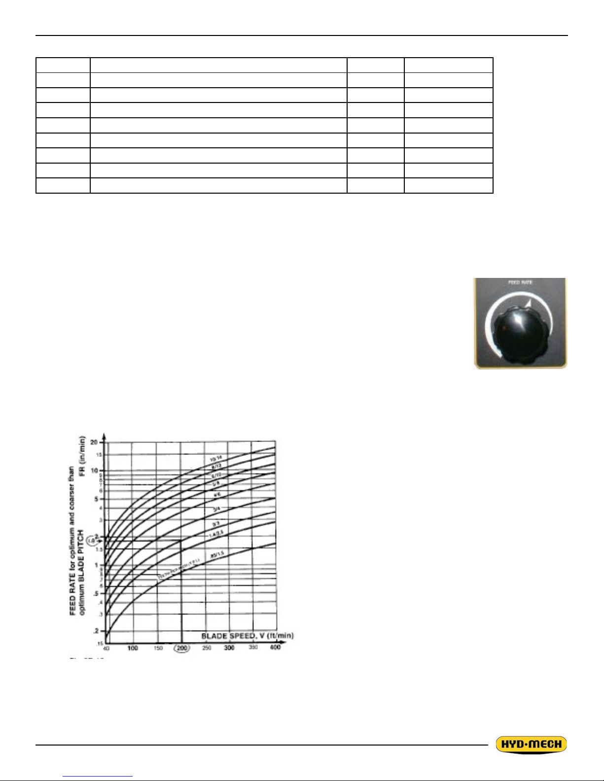
HYDRAULIC FEED CONTROL
The Hydraulic Feed Control is located to the left of the control panel. These controls allow control of Feed Force Limit and
Feed Rate.
Feed Force Knob
Used to set Feed Force Limit (counterclockwise rotation to
increase and clockwise rotation to decrease).
Fast Approach Lever
Depress for fast head descent.
Feed Rate Knob
Used to set Feed Rate (counterclockwise rotation to increase
and clockwise rotation to decrease).
Hydraulic Feed Control
CUTTING PARAMETERS CHART
A full size CUTTING PARAMETERS CHART is mounted on the front of the saw. The chart contains ve steps for the
operator to follow in order to achieve optimum performance of the saw.
Saw Cutting Parameters Chart
2.8
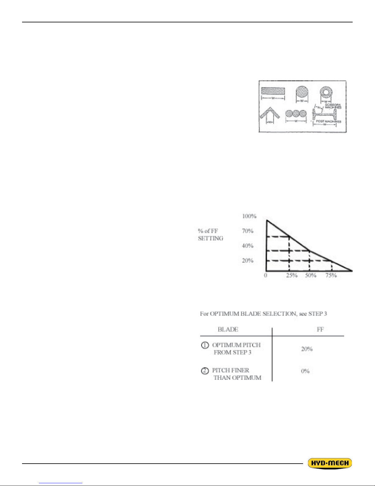
CHART EXAMPLE #1
We will use the parameters chart to set up the saw for cutting 8” (200mm) Diameter #1045 Carbon Steel.
STEP 1, DETERMINE EFFECTIVE MATERIAL WIDTH - W (inches) or (mm)
Effective material width, W (in.) for most common shapes of materials, is the widest solid part of the material to be in contact with blade during cutting. For simple
shapes, as illustrated on the chart, this can be directly measured. For bundles of
tubes and structurals, measuring the effective width is difcult. Effective width is 60%
to 75% of the actual material width.
NOTES:
1. Both effective material width and guide arm width are used in setting the
saw.
2. Guide arm width is the distance between the guide arms and is used in
STEP 2.
Material Width Chart
3. Effective material width, as determined here in STEP 1, can be thought of as the average width of material “seen”
by each tooth, and it is used in STEPS 3 and 4. In Example #1, for an 8” (200 mm) diameter solid, Effective Material Width is 8” (200mm).
STEP 2, SET FEED FORCE LIMIT
The Feed Force Limit is the maximum amount of force with
which the head is allowed to push the blade into the workpiece. FEED FORCE LIMIT should be set with the head in
the down mode, according to the label.
CUTTING SOLIDS
For cutting solids, the wider the section, the less FF should
be set, to avoid blade overloading. See the graph.
EXAMPLE: When cutting a solid which is 1/2 of machine
capacity using the graph, locate 50% on the horizontal line
and travel upwards to the plotted line and then travel directly
across to the vertical FF Setting line. The point that you have
arrived at shows a setting of 40% for a piece 50% of capacity.
CUTTING STRUCTURALS
A reduced Feed Force Setting is used when cutting structurals:
For structurals, a blade ner than Optimum can be used for
more efcient cutting.
MAT’L WIDTH as % of CAPACITY
If a ner than optimum blade is going to be used, Feed Force
Setting should be reduced even further.
2.9
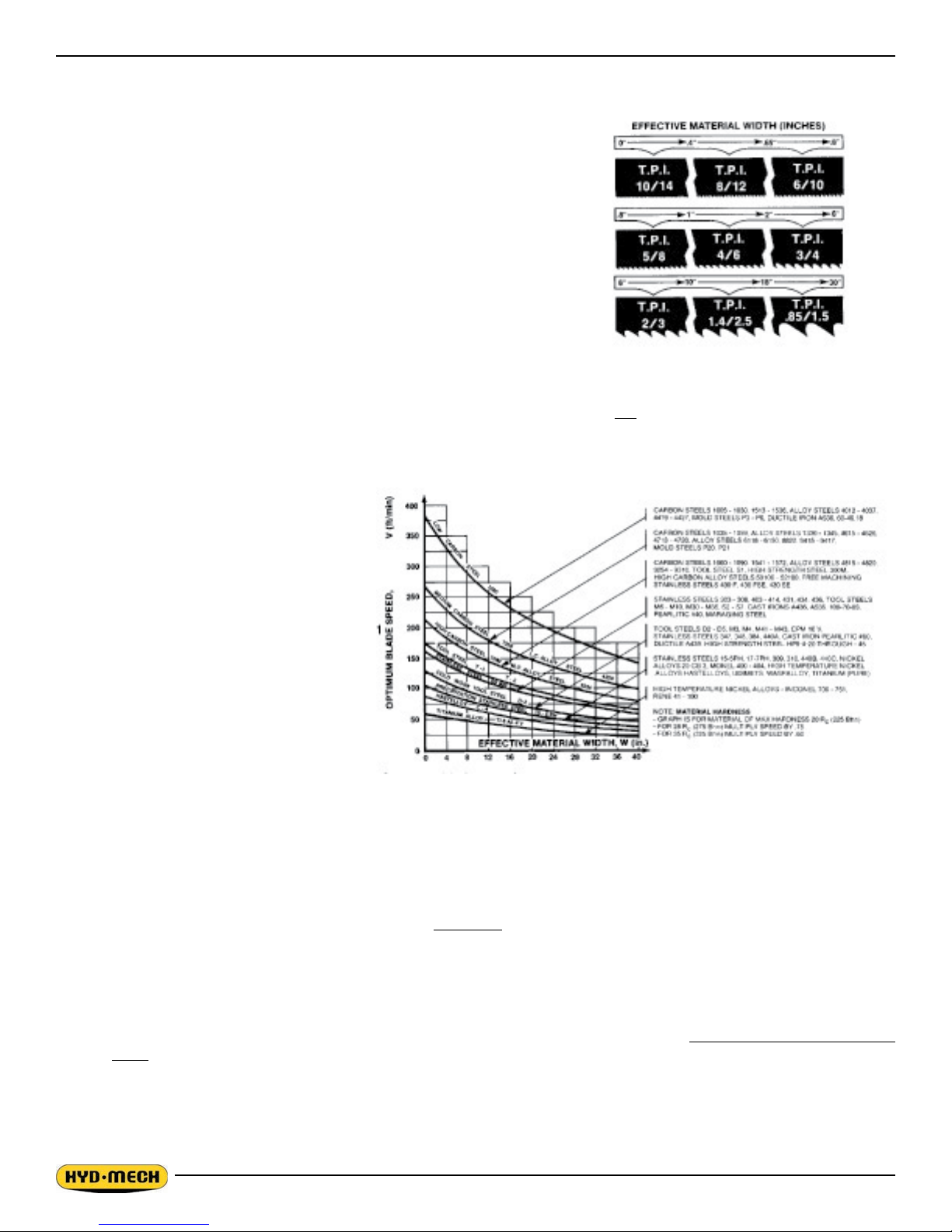
STEP 3, DETERMINE OPTIMUM BLADE PITCH - TEETH PER INCH (T.P.I.)
Selecting a blade with proper tooth pitch is important in order to achieve
optimal cutting rates and good blade life.
For cutting narrow or thin wall structural materials a ne blade with many
teeth per inch (T.P.I.) is recommended. For wide materials a blade with a
coarse pitch should be used. The sketch can be referenced for the blade
pitch changes for differing effective material widths.
It is impractical to change the blade to the proper pitch every time a different width of material is cut and it is not necessary, but remember that
the optimum blade will cut most efciently. Too ne a blade must be fed
slower on wide material because the small gullets between the teeth will
get packed with chips before they get across and out of the cut. Too coarse
a blade must be fed slower because it has fewer teeth cutting and there is
a limit to the depth of a cut taken by each tooth. Allowance for the use of a
non-optimum blade is made in STEP 5.
Optimum Blade Pitch ( T.P.I.
In our Example #1: Effective material width of 8” (200 mm) & Optimum blade has 2/3 teeth per inch.
STEP 4, DETERMINE OPTIMUM BLADE
SPEED, V (ft/min) (m/min)
The relationship between optimum blade
speed and effective material width for various materials is represented on the graph
shown.
The graph shows that as effective material
width gets wider or as material gets harder,
lower blade speeds are recommended. If
material is narrow or soft, higher blades
speeds should be selected.
In Example #1
• 8” (200mm) diameter #1045 Medium Carbon Steel solid bar is to be
cut.
• On the graph above nd the Me-
dium Carbon Steel Curve which
Optimum Blade Speed Curves
represents the optimum blade speeds for 1045 Carbon Steel.
• On the horizontal axis (effective material width axis) nd number 8 which represents effective material width of an
8” (200mm) diameter solid.
• Find the point where a vertical line from 8” (200mm) intersects the Medium Carbon Steel Curve.
• From this intersection point run horizontally left to the vertical axis (optimum blade speed axis) and nd the point
marked “200”.
For 8” (200mm) diameter, 1045 Carbon Steel solid bar 200 ft/min (60m/min) is the optimum blade speed.
NOTE:
1. Higher than optimum blade speed will cause rapid blade dulling. Lower than optimum blade speeds reduce
cutting rates proportionately and do not result in signicantly longer blade life except where there is a vibration
problem. If the blade vibrates appreciably at optimum speed as most often occurs with structurals and bundles, a
lower blade speed may reduce vibration and prevent premature blade failure.
2. Material Hardness - The graph above illustrates blade speed curves for materials of hardness 20 RC (225 Bhn) or
lower. If the material is hardened then the multipliers need to be used. These multipliers are given in the NOTE at
the bottom right of the graph. As the hardness increases the optimum blade speed decreases.
2.10
The following table gives examples of the optimum blade speeds for different materials.
NO. MATERIALS OPTIMUM BLADE SPEED
ft/min m/min
1 5” (125mm) Dia Solid Carbon Steel 225 70
2 12” (300mm) I-Beam 290 90
3 4” x 4”(100 x 100mm) Rec Tube, 1/4” (6mm) Wall 350 110
4 4”(100) 400 Stainless Steel 140 45
5 2” x 2” (50 x 50mm) Rec Tube 1/4” (6mm) Wall
Bundle 5 x 5 pcs 10” x 10” (500 x 500mm)
325 100
6 3” x 3” (75 x 75mm) Inconel 60 20
Materials and Blade Speed
STEP 5, DETERMINE FEED RATE SETTING, FR (in/min) (mm/min).
FEED RATE is the vertical speed at which the blade descends through the work-piece.
The FEED RATE Knob controls FEED RATE of the blade descent in the range 0 to 15 in/min
(380mm/min). The FEED RATE should be adjusted only in one direction (from “O” to required
value). If you go too far, go back to “O” and come back up. To set FEED RATE for particular
cutting situations use the Graph below, which represents the relationship between FEED RATE,
blade speed and blade pitch.
Feed Rate Knob
Feed Rate Calculation
For Example #1, it is known from Step 3 that optimum
blade pitch is 2/3, and from Step 4 that blade speed, is
200 ft/min (60mm/min). From the Graph on the left, the
FEED RATE is determined in the following way:
- On the horizontal axis (blade speed axis), nd 200
ft/min(60mm/min).
- Find the point where a vertical line from 200 ft/min
(60mm/min) would intersect the 2/3 blade pitch curve.
- From this intersection point run horizontally left to the
vertical (FEED RATE) axis, to arrive at 1.8 in/min (45mm/
min) FEED RATE. Thus 1.8 in/min (45mm/min) is the
FEED RATE for cutting 8” (200mm) diameter 1045 Carbon Steel when the optimum 2/3 pitch blade is used.
2.11
 Loading...