

Page 1
SMU 1000
SensorMonitoring Unit
Operating Manual
Valid from firmware versions 3.40 up
English (translation of original instructions)
Documentation no.: 3614430a
Page 2

SMU1000 Imprint
Imprint
Publisher and responsible for the content:
HYDAC FILTER SYSTEMS GMBH
Postfach 1251
66273 Sulzbach / Saarland
Germany
Telephone: +49 (0)6897 509 01
Telefax: +49 (0)6897 509 846
E-mail: filtersystems@hydac.com
Homepage: www.hydac.com
Court of Registration: Saarbrücken, HRB 17216
Executive director: Mathias Dieter,
Dipl.Kfm. Wolfgang Haering
Documentation Representative
Mr. Günter Harge
c/o HYDAC International GmbH, Industriegebiet, 66280 Sulzbach / Saar
Telephone: ++49 (0)6897 509 1511
Telefax: ++49 (0)6897 509 1394
E-mail: guenter.harge@hydac.com
© HYDAC FILTER SYSTEMS GMBH
All rights reserved. No part of this work may be reproduced in any form (print,
photocopy or by other means) or processed, duplicated or distributed using
electronic systems without the written consent of the publisher.
These documents have been created and inspected with the greatest care.
However, errors cannot be ruled out completely.
All details are subject to technical modifications. Technical specifications are subject
to change without notice.
The trademarks of other companies are exclusively used for the products of those
companies.
HYDAC FILTER SYSTEMS GMBH
BeWa SMU1000 34x 3614430a en-us 2012-03-13.doc 2012-03-13
en(us)
Page 2 / 48
Page 3

SMU1000 Content
Content
Imprint .......................................................................................................................2
Documentation Representative...............................................................................2
Content......................................................................................................................3
Preface ......................................................................................................................5
Technical Support...................................................................................................6
Modifications to the Product ...................................................................................6
Warranty .................................................................................................................6
Using the Documentation .......................................................................................7
General Safety Precautions..................................................................................... 8
Obligations and Liability..........................................................................................8
Explanation of Symbols and Warnings, etc. ........................................................... 9
Proper/Designated Use ..........................................................................................9
Improper Use ........................................................................................................ 10
Informal Safety Precautions.................................................................................. 10
Training and Instruction of Personnel ................................................................... 10
Packing, Storage .................................................................................................... 11
Transportation and Packing..................................................................................11
Storage .................................................................................................................11
Scope of Delivery ...................................................................................................11
SMU Features .........................................................................................................12
Installation ..............................................................................................................13
SMU Dimensions and Drilling Template............................................................... 14
Connecting the SMU ..............................................................................................15
Connecting cable SMU <-> sensor .......................................................................16
Power supply -> SMU ........................................................................................... 17
Connection cable AS2000 -> SMU ....................................................................... 17
Connection cable AS8000 -> SMU ....................................................................... 18
Connection cable CS2000 -> SMU.......................................................................18
Operating the SMU ................................................................................................. 19
Keypad.................................................................................................................. 19
Selecting menus and entering values...................................................................19
Selecting main and system menus....................................................................... 20
Status display .......................................................................................................20
Main menu without password protection ..............................................................21
Main menu with password protection ...................................................................21
System Menu........................................................................................................22
SMU setup...............................................................................................................24
Password protection .............................................................................................24
Password setup ....................................................................................................24
Select the scope of the password.........................................................................25
Activating the password........................................................................................25
Access with password protection.......................................................................... 26
Changing the password and range.......................................................................26
HYDAC FILTER SYSTEMS GMBH
BeWa SMU1000 34x 3614430a en-us 2012-03-13.doc 2012-03-13
en(us)
Page 3 / 48
Page 4

SMU1000 Content
Password, delete ..................................................................................................27
Changing the menu language............................................................................... 28
Setting the date and time......................................................................................28
Startup behavior ...................................................................................................29
Setting the LCD contrast and backlighting............................................................ 30
Resetting ................................................................................................................. 31
Reset warm........................................................................................................... 31
Reset cold.............................................................................................................31
Reset original........................................................................................................31
Resetting to the factory settings (factoryset).........................................................31
Factory setting........................................................................................................ 32
Software Update ..................................................................................................... 32
Checking sensor settings (CS1000 / CS2000) .....................................................32
Functions / Menu guide .........................................................................................33
CS 1000 Menu......................................................................................................33
Sensor status CS1000 ......................................................................................34
CS 2000 Menu......................................................................................................34
AS1000 menu ....................................................................................................... 34
AS2000 menu ....................................................................................................... 34
AS8000 menu ....................................................................................................... 34
HLB1000 (HYDACLab).........................................................................................35
Sensor status HLB1000: ...................................................................................35
VLxGW (clogging indicator) .................................................................................. 35
Menus MCS1000 .................................................................................................. 35
Service menu........................................................................................................36
Data logging ...................................................................................................... 37
Data logging status........................................................................................37
Devices .............................................................................................................37
Status CS1000 / HLB.....................................................................................37
Status CS2000 / MCS1000............................................................................ 37
Status AS1000 / AS2000 / AS8000 / VLxGW................................................38
Display Information................................................................................................38
Changeover display mode automatic /manual...................................................... 38
Data format data logger+ ....................................................................................... 39
OPC Variables / OPC Server.................................................................................. 41
Setting up OPC server ...........................................................................................44
Setting - Server.....................................................................................................44
Setting - PLC ........................................................................................................44
Setting connection ................................................................................................44
Disposing of the SMU ............................................................................................45
Customer Service...................................................................................................45
Model Code ............................................................................................................. 46
Measurement sensors combination......................................................................46
Technical Data ........................................................................................................ 47
HYDAC FILTER SYSTEMS GMBH
BeWa SMU1000 34x 3614430a en-us 2012-03-13.doc 2012-03-13
en(us)
Page 4 / 48
Page 5

SMU1000 Preface
Preface
For you, as the owner of a product manufactured by us, we have produced this
manual, comprising the most important instructions for its operation and
maintenance.
It will acquaint you with the product and assist you in using it as intended in an
optimal manner.
Keep it in the vicinity of the product so it is always available.
Note that the information on the unit's engineering contained in the documentation
was that available at the time of publication.There may be deviations in technical
details, figures, and dimensions as a result.
If you discover errors while reading the documentation or have additional comments
or suggestions, contact us at:
HYDAC FILTER SYSTEMS GMBH
Technische Dokumentation
Postfach 12 51
66273 Sulzbach / Saar
Germany
We look forward to receiving your input.
“Putting experience into practice”
HYDAC FILTER SYSTEMS GMBH
BeWa SMU1000 34x 3614430a en-us 2012-03-13.doc 2012-03-13
en(us)
Page 5 / 48
Page 6

SMU1000 Preface
Technical Support
Contact our technical sales department if you have any questions on our product.
When contacting us, please always include the model/type designation, serial no.
and part-no. of the product:
Fax: ++49 (0) 6897 / 509 - 846
E-mail: filtersystems@hydac.com
Modifications to the Product
We would like to point out that changes to the product (e.g. purchasing additional
options, etc.) may mean that the information in the operating instructions is no
longer applicable or adequate.
After modification or repair work that affects the safety of the product has been
carried out on components, the product may not be returned to operation until it has
been checked and released by a HYDAC technician.
Please notify us immediately of any modifications made to the product whether by
you or a third party.
Warranty
For the warranty provided by us, please refer to the General Terms of Sale and
Delivery of HYDAC FILTER SYSTEMS GmbH.
Refer to these at www.hydac.com General terms and conditions.
HYDAC FILTER SYSTEMS GMBH
BeWa SMU1000 34x 3614430a en-us 2012-03-13.doc 2012-03-13
en(us)
Page 6 / 48
Page 7
SMU1000 Preface
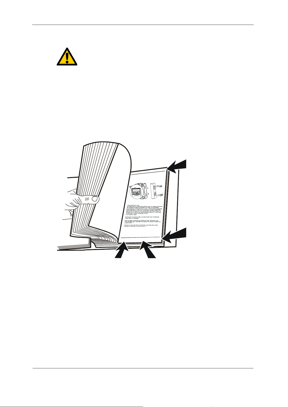
Using the Documentation
Note that the method described for locating specific information does
not release you from your responsibility of carefully reading these
instructions prior to starting the unit up for the first time and at regular
intervals in the future.
What do I want to know?
I determine which topic I am looking for.
Where can I find the information I’m looking for?
The documentation has a table of contents at the beginning. There, I select
the chapter I'm looking for and the corresponding page number.
Product description /
l
t
e
i
p
a
K
t
/
k
d
u
o
P
r
Chapter heading
Page number
i
l
t
e
t
e
c
r
h
n
i
k
G
m
b
H
H
Y
D
C
A
F
B
2
a
1
4
e
a
d
3
6
W
5
de
e
200x-xx-xx
Seite x
Edition date
Documentation no.
Document language
with index/
file name
The documentation number with its index enables you to order another copy of the
operating and maintenance instructions. The index is incremented every time the
manual is revised or changed.
HYDAC FILTER SYSTEMS GMBH
BeWa SMU1000 34x 3614430a en-us 2012-03-13.doc 2012-03-13
en(us)
Page 7 / 48
Page 8

SMU1000 General Safety Precautions
General Safety Precautions
These operating instructions contain the key instructions for properly and safely
operating the SMU.
Obligations and Liability
The basic prerequisite for the safe and proper handling and operation of the
SMU is knowledge of the safety instructions and warnings.
These operating instructions in general, and the safety precautions in particular,
are to be adhered by all those who work with the SMU.
Adherence is to be maintained to pertinent accident prevention regulations
applicable at the site where the product is used.
The safety precautions listed herein are limited solely to using the SMU.
The SMU has been designed and constructed in accordance with the current
state of the art and recognized safety regulations. Nevertheless, hazards may be
posed to the life and limb of the individual using the product or to third parties.
Risk of damage may be posed to the product or other equipment and property.
The SMU is only to be used as follows:
solely for its designated use
only when in a safe, perfect condition
Any faults or malfunctions which might impair safety are to be properly repaired
or remedied immediately.
Our General Terms and Conditions (AGB) apply. They are made available to the
owner upon concluding purchase of the unit at the latest. Any and all warranty
and liability claims for personal injuries and damage to property shall be
excluded in the event they are attributable to one or more of the following
causes:
improper use of the SMU or use deviating from its designated use
improper assembly, installation, commissioning, operation and maintenance
of the SMU
Modifications to the SMU made by the user or purchaser
improperly performed repair work
HYDAC FILTER SYSTEMS GMBH
BeWa SMU1000 34x 3614430a en-us 2012-03-13.doc 2012-03-13
en(us)
Page 8 / 48
Page 9
SMU1000 General Safety Precautions
Explanation of Symbols and Warnings, etc.
The following designations and symbols are used in this manual to designate
hazards, etc.:
DANGER denotes situations
which can lead to death if
DANGER
WARNING
CAUTION
NOTICE
safety precautions are not
observed.
WARNING denotes situations
which can lead to death if
safety precautions are not
observed.
CAUTION denotes situations
which can lead to severe
injuries if safety precautions
are not observed.
NOTICE denotes situations
which can lead to property
damage if safety precautions
are not observed.
Proper/Designated Use
The SensorMonitoring Unit was developed to continuously record values measured
by HYDAC sensors.
Analyzing the type, size and quantity of contamination enables quality standards to
be verified and documented, and the requisite optimization measures to be
implemented.
Any other use shall be deemed to be improper and not in keeping with the product's
designated use; the manufacturer accepts no liability for any damage resulting from
such use.
Proper or designated use of the product extends to the following:
The continuous recording of values measured by HYDAC sensors
Maintaining adherence to all the instructions contained herein.
HYDAC FILTER SYSTEMS GMBH
BeWa SMU1000 34x 3614430a en-us 2012-03-13.doc 2012-03-13
en(us)
Page 9 / 48
Page 10

SMU1000 General Safety Precautions
Improper Use
Any use deviating from the proper/designated use described above is prohibited.
Improper use may result in hazard to life and limb.
Example of improper use:
- improper connection of the SMU voltage and sensor cables.
Informal Safety Precautions
Make sure to always keep the operating instructions in the vicinity of the SMU.
In addition to the manual, the general and local regulations concerning accident
prevention and protection of the environment should be available and observed.
Training and Instruction of Personnel
The SMU may only be operated by properly trained and instructed personnel.
The areas of responsibility of your staff must be established in a clear-cut manner.
Staff undergoing training may not use the SMU unless supervised by an
experienced staff member.
Individuals
Individuals
undergoing
training
Individuals with
technical training/
engineering
background
Electrician
Supervisor with the
appropriate
Activity
Packing
Transportation
Commissioning
Operation
X X
X X X
X X X X
X
Troubleshooting/
locating the source of
X X X
malfunction
authority
Remedying of mechanical faults
X
Remedying of electrical faults
Maintenance
X X X X
Servicing
Decommissioning /
Storage
HYDAC FILTER SYSTEMS GMBH
BeWa SMU1000 34x 3614430a en-us 2012-03-13.doc 2012-03-13
en(us)
X X X X
X
X X
X
Page 10 / 48
Page 11

SMU1000 Packing, Storage
Packing, Storage
Transportation and Packing
The SMU comes packed in a cardboard box.
Unpack the unit and check it for damage in transit. Report any damage to the
forwarding agent immediately.
Storage
Make sure to store the SMU in a clean, dry place, in the original packing, if possible.
Do not remove the packing until you are ready to install the unit.
Scope of Delivery
The SMU comes packed and factory-assembled. Before commissioning the SMU,
check the content of the package to make sure everything is present.
The following items are supplied:
Qty. Designation
1 SensorMonitoring Unit - SMU 1000
1 MMC card 128 MB including card holder
1 Power supply cable, length = 5m, (ZBE 08-05)
3 Connection cable in accordance with the model code or the sensors
to be read off
1 Operation and Maintenance Instructions (this document)
1 SMU Support CD
1 FluMoS Light CD
HYDAC FILTER SYSTEMS GMBH
BeWa SMU1000 34x 3614430a en-us 2012-03-13.doc 2012-03-13
en(us)
Page 11 / 48
Page 12

SMU1000 SMU Features
SMU Features
The SensorMonitoring Unit SMU is a small control unit for saving measured values
on an MMC memory card.
The following fluid sensors can be connected directly, depending on model code:
- ContaminationSensor CS1000, CS2000
- AquaSensor AS 1000, AS 2000, AS 8000
- HYDACLab
- GW display
- MCS1000
The display shows the fluctuating measured values of the connected sensors.
The measured values are saved in a file on the card in data exchange format *.csv
every 60 seconds (a 128 MB memory card records ~ 3 years' worth of data).
For further processing and evaluation, the data can simply be transferred to Office
applications, e.g. FluMoS or MS Excel.
Uses for the SMU include:
- Storage of data from fluid monitoring in the field.
- Test installation to validate sensors
Advantages offered by the SMU unit:
- Cost-effective, easy-to-install solution
- Simple data processing and evaluation with FluMoS or MS Excel
- Ethernet interface for OPC servers (optional)
- Program restarts independently after a voltage loss
HYDAC FILTER SYSTEMS GMBH
BeWa SMU1000 34x 3614430a en-us 2012-03-13.doc 2012-03-13
en(us)
Page 12 / 48
Page 13

SMU1000 Installation
Installation
In the availability status, the project is located on the control unit. The application
starts automatically when the power supply is switched on.
During the initial installation or in the case of a longer service life without power, the
system clock should be checked and reset if necessary.
The system clock is checked when the program starts. If this times out, the following
message appears on the display: „SET CLOCK -> Reboot system“. To set the
system clock, first press the ESC to switch to the main menu. Set the hour and date
by pressing the ALT button several times (see Setting the system clock on page 28).
The installat
ion phase lasts ~ 105 seconds and appears on the start page as a %
specification.
The sensors are connected to the M12-unit plug on the underside of the SMU.
The analog output signal of the sensors must be checked or set before
commissioning. For details, see page 32.
For all sensors, the SMU requires a 4-20 mA signal for analog input (no
CS 1000
with a 0-10 V voltage signal!).
When using the SMU as a data logger, the memory card must be correctly inserted.
This will show up on the display as "MC". To check this when the program is
running, press the "ESC" button to switch to the main menu.
HYDAC FILTER SYSTEMS GMBH
BeWa SMU1000 34x 3614430a en-us 2012-03-13.doc 2012-03-13
en(us)
Page 13 / 48
Page 14
SMU1000 SMU Dimensions and Drilling Template
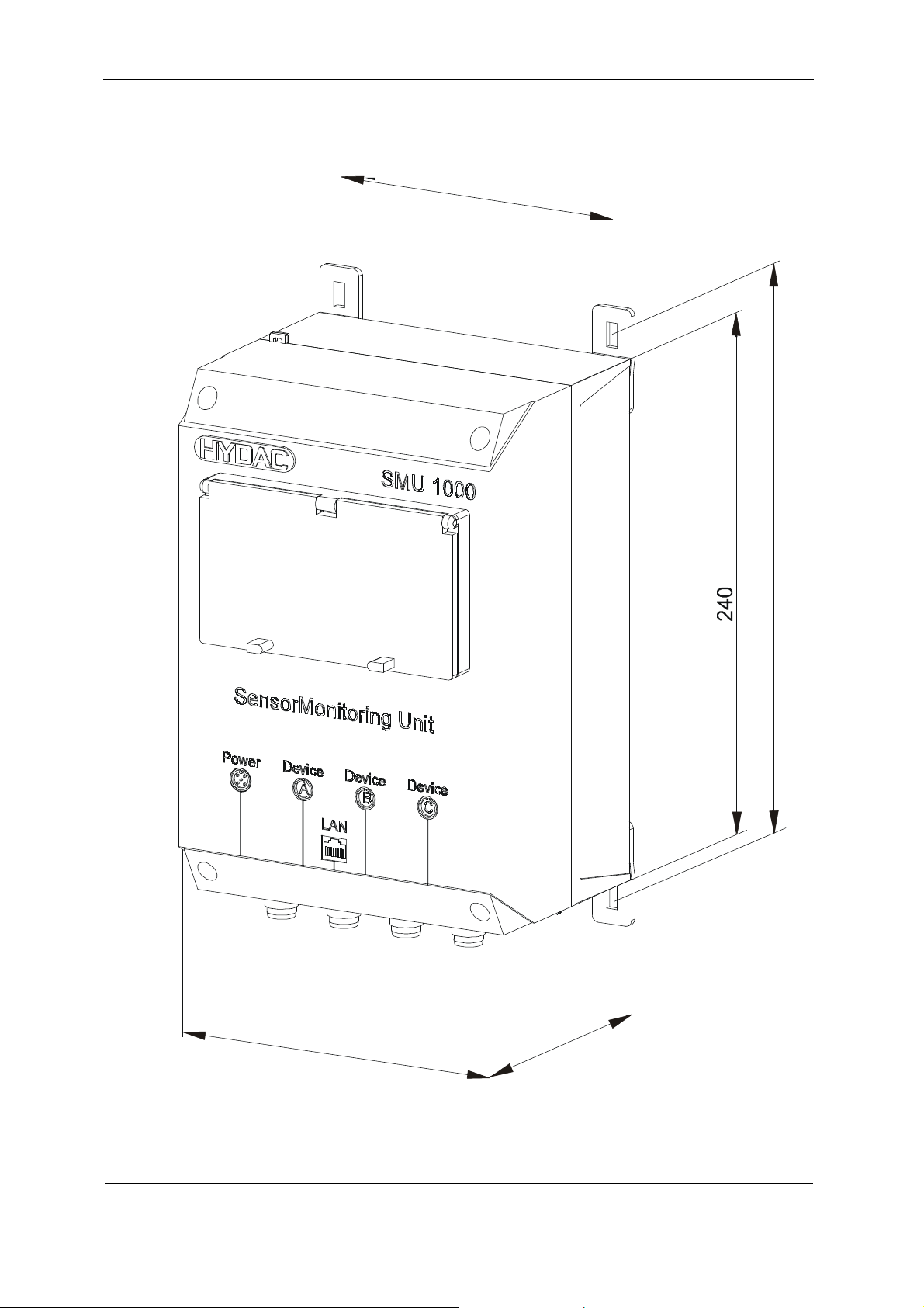
SMU Dimensions and Drilling Template
1
40
5
5
2
1
6
0
5
2
1
HYDAC FILTER SYSTEMS GMBH
BeWa SMU1000 34x 3614430a en-us 2012-03-13.doc 2012-03-13
en(us)
Page 14 / 48
Page 15
SMU1000 Connecting the SMU
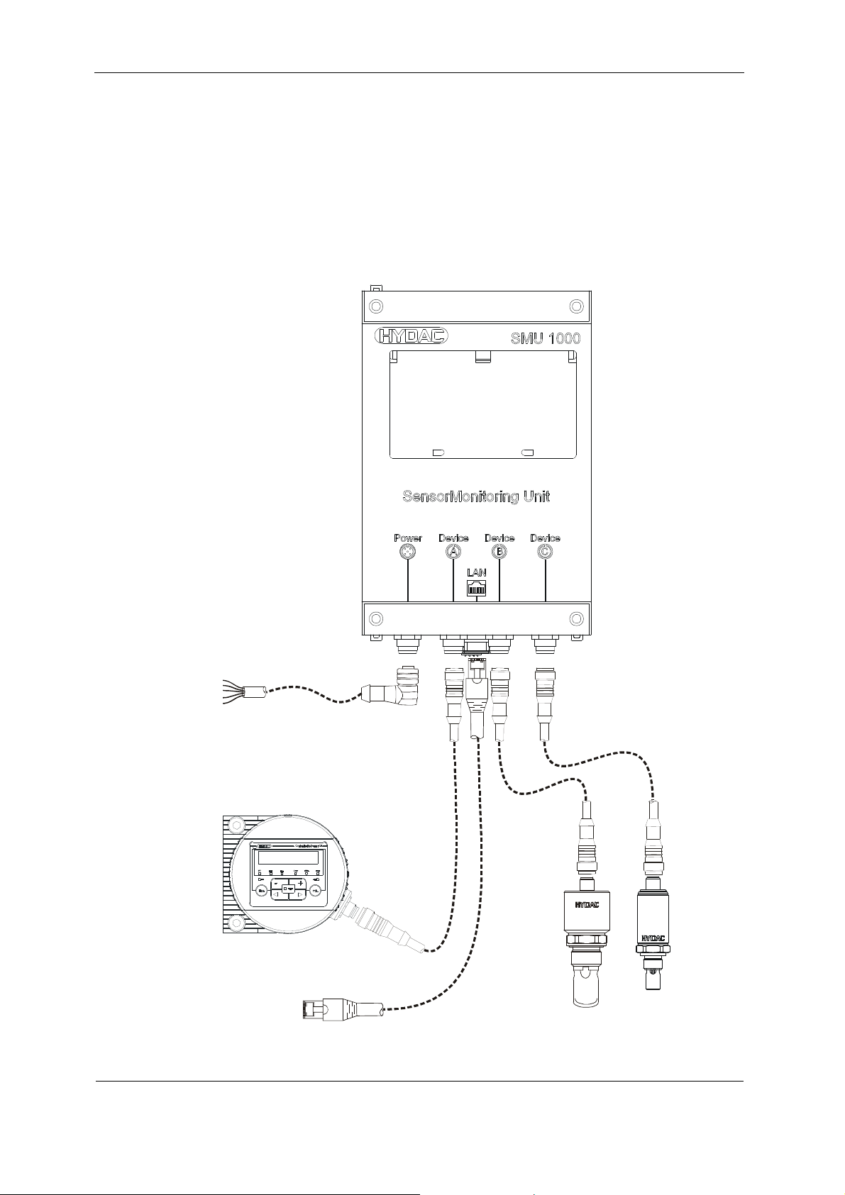
Connecting the SMU
The connections (DEVICE A / B / C) are each assigned to a specific sensor and
cannot be assigned at will.
For the assignment of the sensors, observe the sensor index on the rating plate of
the SMU. You can find a table for the identification of the SMU <-> measurement
sensor combination on page 46.
Connection
5
example with: CS1000 / HYDACLab (HLB) / AS1000
24 V DC
Power
CS 1000
RJ45
Ethernet
HYDACLab
HYDAC FILTER SYSTEMS GMBH
BeWa SMU1000 34x 3614430a en-us 2012-03-13.doc 2012-03-13
en(us)
AS 1000
Page 15 / 48
Page 16

SMU1000 Connecting cable SMU <-> sensor
Connecting cable SMU <-> sensor
Ready-made cables are available for the vast majority of sensors to be connected.
For connection to the SMU, these cables must be merely plugged in and tightened.
However, some sensors have a clamp gib which the open cable ends have to be
connected to.
NOTICE
Electrical short circuit
The SMU will be destroyed
► Insulate all unnecessary wires to prevent them from accidentally touching
each other.
The color coding of the connection cable is valid only for cables from
the SMU scope of delivery and original replacement cables.
5-pin connection cable, open cable end:
5
1
4
2
3
8-pin connection cable, open cable end:
Schirm
8
1
7
6
5
2
Shield
Blindage
3
4
Schirm
Shield
Blindage
1
braun
weiss
2
blau
/ blue / bleu
3
schwarz
4
grau
/ grey / gris
5
weiss
1
braun
2
grün
3
gelb
4
grau
5
rosa / pink / rose
6
7
blau
/ brown / brun
/ white / blanc
/ black / noir
/ white / blanc
/ brown / brun
/ green / vert
/ yellow / jaune
/ grey / gris
/ blue / bleu
8
rot
/ red / rouge
Schirm
/ Shield / Blindage
HYDAC FILTER SYSTEMS GMBH
BeWa SMU1000 34x 3614430a en-us 2012-03-13.doc 2012-03-13
en(us)
Page 16 / 48
Page 17

SMU1000 Connecting cable SMU <-> sensor
Power supply -> SMU
To connect the power supply, you need a 5-pin connection cable. The connection
assignment must be made in accordance with the following table.
Schirm
5
1
4
Pin Color code Designation Connection
1 Brown Voltage + 24 V DC
2 White
3 Blue Voltage GND 0 V DC
4 Black
5 Gray
2
Shield
Blindage
3
1
braun
weiss
2
blau
3
schwarz
4
grau
5
/ brown / brun
/ white / blanc
/ blue / bleu
/ black / noir
/ grey / gris
Connection cable AS2000 -> SMU
To connect the AS2000, you need a 5-pin connection cable. The connection
assignment must be made in accordance with the following table.
1
4
Pin Color code Designation Terminal on the
1 Brown Voltage + 24 V DC
2 White "Saturation" analog output 4 ... 20 mA Saturation(-)
3 Blue
4 Black "Temperature" analog output 4 ... 20 mA Temperature(-)
5 Gray
Schirm
5
Shield
2
Blindage
1
braun
/ brown / brun
weiss
/ white / blanc
2
3
blau
/ blue / bleu
3
schwarz
4
grau
5
/ black / noir
/ grey / gris
AS2000
HYDAC FILTER SYSTEMS GMBH
BeWa SMU1000 34x 3614430a en-us 2012-03-13.doc 2012-03-13
en(us)
Page 17 / 48
Page 18

SMU1000 Connecting cable SMU <-> sensor
Connection cable AS8000 -> SMU
To connect the AS8000, you need an 8-pin connection cable. The connection
assignment must be made in accordance with the following table.
Pin Color code Designation Terminal on the
AS8000
1 White Voltage + 24 V DC 24 V
2 Brown Analog output S1+ S1+
3 Green Voltage 0 V DC 0 V
4 Yellow Analog output S2+ S2+
5 Gray
6 Pink Analog output S1- GND S17 Blue
8 Red Analog output S2- GND S2-
Connection cable CS2000 -> SMU
To connect the CS2000, you need an 8-pin connection cable. The connection
assignment must be made in accordance with the following table.
Schirm
8
1
7
6
5
2
Shield
Blindage
3
4
1
2
3
4
weiss
braun
grün
gelb
/ white / blanc
/ brown / brun
/ green / vert
/ yellow / jaune
grau
/ grey / gris
5
rosa / pink / rose
6
7
blau
/ blue / bleu
rot
/ red / rouge
8
Schirm
/ Shield / Blindage
Pin Color code Designation Terminal on the
CS2000
1 White Voltage + 24 V DC
2 Brown
3 Green Voltage GND GND
4 Yellow
5 Gray PNP output to PLC 3
6 Pink
7 Blue PLC GND 1
8 Red 24 V from PLC 2
HYDAC FILTER SYSTEMS GMBH
BeWa SMU1000 34x 3614430a en-us 2012-03-13.doc 2012-03-13
en(us)
Page 18 / 48
Page 19

SMU1000 Operating the SMU
Operating the SMU
The following chapter describes the operation of the buttons and the display on the
front plate.
Keypad
DEL
Delete or return to applications program from
main menu
A
L
T
Special function, status display
Cursor buttons ▲ ▼ ◄ ►:
Move cursor
Select menu items
Set numbers and values
OK
Next menu level, save entry
E
S
C
Previous menu level, cancel
Selecting menus and entering values
DEL
and
Call up system functions
A
L
T
Move to next menu level
OK
Call menu item
Activate, change, save entry
Move to previous menu level
E
S
C
Cancel entries since last OK
▲ Change menu item
♣▼ Change value, change place
◄► P-button function
▲ Input P1 ► Input P2
▼ Input P3 ◄ Input P4
HYDAC FILTER SYSTEMS GMBH
BeWa SMU1000 34x 3614430a en-us 2012-03-13.doc 2012-03-13
en(us)
Page 19 / 48
Page 20

SMU1000 Selecting main and system menus
Selecting main and system menus
Status display
HYDAC FILTER SYSTEMS GMBH
BeWa SMU1000 34x 3614430a en-us 2012-03-13.doc 2012-03-13
en(us)
Page 20 / 48
Page 21

SMU1000 Selecting main and system menus
Main menu without password protection
Main menu with password protection
HYDAC FILTER SYSTEMS GMBH
BeWa SMU1000 34x 3614430a en-us 2012-03-13.doc 2012-03-13
en(us)
Page 21 / 48
Page 22

SMU1000 Selecting main and system menus
System Menu
HYDAC FILTER SYSTEMS GMBH
BeWa SMU1000 34x 3614430a en-us 2012-03-13.doc 2012-03-13
en(us)
Page 22 / 48
Page 23

SMU1000 Selecting main and system menus
HYDAC FILTER SYSTEMS GMBH
BeWa SMU1000 34x 3614430a en-us 2012-03-13.doc 2012-03-13
en(us)
Page 23 / 48
Page 24

SMU1000 SMU setup
SMU setup
Settings are all changed using the operating elements on the control unit.
Password protection
You can protect access to the main menu and system menu, the clock setting and
the operating mode (RUN/STOP) with a password. Choose <Security l Range> for
the individual setting options.
The system menu is always protected when a password is activated.
The password consists of a value between 000001 and 999999.
Clear a password with the number combination of 000000.
Password setup
A password can be set in the system menu in either the RUN or STOP mode. You
cannot change to the system menu if a password is already activated.
Press DEL and ALT to call up the system menu.
Select the menu option SECURITY to enter the password.
Press the OK button and move to the password menu.
Press OK again for the password entry mode.
Six dashes will appear if no password is entered:
No password present.
Press OK, and six zeroes will appear
Set the password using the cursor button:
◄ ►:Select position in the password,
▲ ▼ Set a value between 0 and 9.
Save the new password by pressing OK.
Press OK to exit the password menu and press
ESC and ▼ to the RANGE menu...
The scope of the password has not yet been
defined. The password is now valid but not yet
activated.
HYDAC FILTER SYSTEMS GMBH
BeWa SMU1000 34x 3614430a en-us 2012-03-13.doc 2012-03-13
en(us)
Page 24 / 48
Page 25

SMU1000 SMU setup
Select the scope of the password
Confirm with the OK button.
Select the function or menu to be protected.
Press OK to protect the function or menu
(checked box = protected).
The password protects the program by default.
At least one function or one menu must be protected.
PROGRAM: The PROGRAM menu is protected.
CLOCK: Date and time are password-protected.
OPERATING MODE: The toggling of the RUN or STOP operating mode is
protected.
Activating the password
You can activate an existing password in four different ways:
- Automatically when the control unit restarts.
- Automatically after the program is loaded.
- Automatically if no telegram was sent to the computer interface 30 minutes after
the password was entered.
- Via the password menu.
► Press DEL and ALT to call up the system
menu.
► Open the password menu via the SECURITY
menu item...
The password menu is displayed only if a
password is present.
The password protects the program by default.
Make note of the password before activating it. If you forget the
password, you will not be able to access the system menu.
► Select CHANGE PW and press OK.
The password is now activated. The status display is activated.
You must enter the password before you can access a protected function, a
protected menu or the system menu.
HYDAC FILTER SYSTEMS GMBH
BeWa SMU1000 34x 3614430a en-us 2012-03-13.doc 2012-03-13
en(us)
Page 25 / 48
Page 26

SMU1000 SMU setup
Access with password protection
Password protection is deactivated after the password is entered. You can
reactivate the password later using the password menu or by switching the power
supply off and the on again.
► Press OK to switch to the main menu.
The PASSWORD... entry will flash.
► Press OK to call up the password entry
screen.
If the main menu shows PROGRAM instead of PASSWORD...,
this means that password protection is not activated.
The password entry field is shown.
► Set the password using the cursor button.
► Confirm with OK.
If the password entry is correct, the status display is reactivated.
The menu item PROGRAM... is enabled.
The system menu is also accessible.
Changing the password and range
► Enter your password.
► Press DEL and ALT to call up the system menu.
► Open the password menu via the SECURITY and PASSWORD... menu item.
The entry CHANGE PW will flash.
This menu is only displayed if a password is
present.
HYDAC FILTER SYSTEMS GMBH
BeWa SMU1000 34x 3614430a en-us 2012-03-13.doc 2012-03-13
en(us)
Page 26 / 48
Page 27

SMU1000 SMU setup
► Press OK for the password entry field.
► Press OK to move to the 6-digit entry field.
► The current password will be displayed.
► Change the six password digits with the
cursor buttons.
► Confirm with OK.
Press ESC to exit the security menu.
Password, delete
Use the number combination of 000000 to clear a
password.
Six dashes will appear if no password is entered.
Password incorrect or no longer known
Have you entered an incorrect password?
Re-enter the password.
This can be repeated as many times as require!
Pressing ESC returns you to the start menu.
If you forget the password, you can only call up the browser command
"factoryset." The password, user program, and boot project will be
deleted and the command unit will be reinitialized with the default
parameters; see section "Reset".
HYDAC FILTER SYSTEMS GMBH
BeWa SMU1000 34x 3614430a en-us 2012-03-13.doc 2012-03-13
en(us)
Page 27 / 48
Page 28

SMU1000 SMU setup
Changing the menu language
You can set the menu languages German and English using the system menu.
The language option is only available if the control unit is not protected
by a password.
Press DEL and ALT to call up the system menu.
To change the menu language, select MENU LANGUAGE .
The option ENGLISH is displayed.
Select the new menu language with ▲ or ▼.
Confirm with OK. Enter a check mark next to
"language".
Exit the menu with ESC.
The new menu language is activated.
Press ESC to return to the status display.
Setting the date and time
The units are provided with a real-time clock with date and time. During the first
commissioning, set the hour, minute, day, month, and year.
► Select SET CLOCK... in the main menu.
The clock setting menu will flash.
► Select SET CLOCK:
► Enter the values for hour, day, month, and
year.
► Press OK to access the entry mode.
– ◄► Select location.
– ▲▼ Change the value.
– OK Save date and time.
– ESC Keep previous setting.
Press ESC to leave the clock setting display.
:
:
:
:
:
:
:
HYDAC FILTER SYSTEMS GMBH
BeWa SMU1000 34x 3614430a en-us 2012-03-13.doc 2012-03-13
en(us)
Page 28 / 48
Page 29

SMU1000 SMU setup
Startup behavior
Setting the startup behavior
The following startup options can be set using the menu.
STOP
WARM START
COLD START
► Switch to the system menu.
If the control unit is protected by a password, the system menu can only
be accessed after entering the password (see section "Access with
password protection," page 26).
►
Set the startup behavior.
HYDAC FILTER SYSTEMS GMBH
BeWa SMU1000 34x 3614430a en-us 2012-03-13.doc 2012-03-13
en(us)
Page 29 / 48
Page 30

SMU1000 SMU setup
Setting the LCD contrast and backlighting
The background lighting of the LCD display can be switched off. The display
contrast can be set to one of 5 levels. The display is not needed during operation.
Backlighting is only required during maintenance and when texts are being
displayed.
► Switch to the system menu.
If the control unit is protected by a password, the system menu can only
be accessed after entering the password; see "Access with password
protection," page 26.
►
Select the SYSTEM menu.
► Confirm with the OK button.
► Select the DISPLAY menu with the cursor
keys ▲ and ▼ and confirm with OK.
The menus for setting the contrast and backlighting are displayed.
► Press OK to access contrast entry mode.
Using the cursor buttons ▲ and ▼, change the
contrast to a value between -2 and +2.
► Select your setting.
► Confirm the setting with the OK button.
The contrast setting remains the same until you change it.
► Switch to the LIGHTING menu using the
cursor buttons ▲ and ▼.
► Confirm with the OK button.
► The background lighting is deactivated.
► If you want to reactivate the background
lighting, press the OK button.
► The check mark ✔ shows that the background
lighting is activated.
HYDAC FILTER SYSTEMS GMBH
BeWa SMU1000 34x 3614430a en-us 2012-03-13.doc 2012-03-13
en(us)
Page 30 / 48
Page 31

SMU1000 Resetting
Resetting
You can reset the system using the PC in the online mode or via the menu of the
controller. To do so, select the menu item in the control configurator or in the menu
of the controller.
Reset commands are described in detail below
Reset warm
The program is stopped.
The non-remanent variables are initialized; the "retain" variables are retained.
The program can be restarted.
Reset cold
The program is stopped.
All variables are initialized.
The program can be restarted.
Reset original
The program in the working memory and the boot project in the system memory of
the controller are deleted.
With a memory card plugged in:
- All project-specific files on the memory card, the operating system, and
the boot project are deleted.
- All user-specific files and the startup.ini file remain unchanged
The controller is set to the NOT READY condition.
Resetting to the factory settings (factoryset)
Using the browser command "factoryset" or the controller's menu item <SYSTEM l
WERKSEINSTELLUNG>, a "Reset original" is performed (see section "Reset
original").
In addition, the Startup.ini file on the memory card and the system parameters in the
controller are deleted. After a start the controller works with the STARTUP data
again. The interfaces are initialized with their default values.
HYDAC FILTER SYSTEMS GMBH
BeWa SMU1000 34x 3614430a en-us 2012-03-13.doc 2012-03-13
en(us)
Page 31 / 48
Page 32

SMU1000 Factory setting
Factory setting
The basic settings when the SMU is delivered are:
- The contrast is at the setting 0.
- The background lighting is constantly activated.
- Menu setting: LIGHTING ✔
Software Update
If the existing program was deleted (see controller main menu), the program is
available on the SMU support CD.
To do this, copy the files under "SMU1000Bootprojekt_Vxxx" onto the memory card.
Then disable the write-protection of the files on the MMC card. Select the files and
open the properties by right-clicking. Remove the checkmark next to "Writeprotected".
When the memory card is inserted, the program is automatically loaded again with a
system restart.
If the program has been deleted (see main menu "Control unit"), the program is still
saved on the memory card and can be loaded automatically by restarting the
system. You can also carry out a software update in this way.
Checking sensor settings (CS1000 / CS2000)
The connected sensors CS1000 and CS2000 must be set up or adjusted for
operation with the SMU in accordance with the following table.
You can find details in the corresponding sensor documentation.
The sensors AS1000 / AS2000 / AS8000 / HYDACLab and VLxGW do not need
further adjustment for operation on the SMU.
Sensor Settings
CS1000 ANA.OUT = HDA.ISO
Measurement time = 60 sec.
CS2000 The PLC output must give a signal based on the ISO code.
MCS1000 Evaluation is only possible from switching output 1.
Configure the MCS accordingly.
HYDAC FILTER SYSTEMS GMBH
BeWa SMU1000 34x 3614430a en-us 2012-03-13.doc 2012-03-13
en(us)
Page 32 / 48
Page 33

SMU1000 Functions / Menu guide
Functions / Menu guide
A maximum of three sensors can be connected to the SMU. The combination of sensors to
be connected depends on the sensor index in the model code (for details see page ).
The program of the SMU is divided into the following submenus:
- Start page
- CS 1000 (ContaminationSensor)
- CS 2000 (ContaminationSensor)
- AS1000 (AquaSensor)
- AS2000 (AquaSensor)
- AS8000 (AquaSensor)
- HLB1000 (HYDACLab)
- VLxGW (clogging indicator)
- MCS1000 (Metallic ContaminationSensor)
- Service menu
- Datalogging
- Units
- Information
The sensor data is automatically displayed in ~ 5 second intervals.
The OK button can also be used to switch between manual (using cursors ◄►) and
automatic display.
You can find more detailed information on the individual menu pages in the
corresponding chapters.
CS 1000 Menu
Display of the current measured values and of the sensor status
State: = Sensor status CS1000
CISO: = ISO-Code for 0 -> 4 µm Channel
C1 -> 6 µm Channel
C2 -> 14 µm Channel
C3 -> 21 µm Channel
HYDAC FILTER SYSTEMS GMBH
BeWa SMU1000 34x 3614430a en-us 2012-03-13.doc 2012-03-13
en(us)
Page 33 / 48
Page 34

SMU1000 Functions / Menu guide
Sensor status CS1000
0 = "Undefined": error in the evaluation of the status signal
1 = "OK..." : CS is functioning without errors
2 = "Error..." : Unit error / CS not ready
3 = "Flow 2 Low": Flow too low
4 = „ISO <9<8<7“: Flow too high
5 = "No value": no measured value (flow undefined)
CS 2000 Menu
Display of the current measured values and of the unit status
ISO: = ISO code
AS1000 menu
Display of the current measured values
AS2000 menu
Display of the current measured values
AS8000 menu
Display of the current measured values
Sat: = Water saturation in %
T: = Temperature in °C
Sat: = Water saturation in %
T: = Temperature in °C
Sensor1: = Water saturation in %
Sensor2: = Water saturation in %
HYDAC FILTER SYSTEMS GMBH
BeWa SMU1000 34x 3614430a en-us 2012-03-13.doc 2012-03-13
en(us)
Page 34 / 48
Page 35

SMU1000 Functions / Menu guide
HLB1000 (HYDACLab)
Display of the current measured values and of the sensor status
V = relative change of viscosity in %
DK = relative change in dielectric constant value in %
Sat = Water saturation degree in %
T = Temperature in °C
State = Sensor status
Sensor status HLB1000:
0 = "Undefined": error in the evaluation of the status signal
1 = „Reference“: Reference phase
2 = „Operating“: Operating phase
3 = „OutOfRange“: oil status not plausible
4 = „Error“: Internal error
VLxGW (clogging indicator)
Display of the current measured values and of the sensor status
Pin = Inlet pressure
DeltaP = Pressure differential
Menus MCS1000
Display of the current measured values and of the sensor status
Sum = Number of particles, output on switching output
xxx = Valu
1
HYDAC FILTER SYSTEMS GMBH
BeWa SMU1000 34x 3614430a en-us 2012-03-13.doc 2012-03-13
en(us)
Page 35 / 48
Page 36

SMU1000 Functions / Menu guide
Service menu
The selected menu item flashes in the service menu. Select the next menu item with
the cursor buttons ▲▼ and press OK.
You can exit the service menu or return to the sensor data display by pressing the
DEL button.
You cannot switch from the service menu to the control unit menu. The ESC button
is blocked.
HYDAC FILTER SYSTEMS GMBH
BeWa SMU1000 34x 3614430a en-us 2012-03-13.doc 2012-03-13
en(us)
Page 36 / 48
Page 37

SMU1000 Functions / Menu guide
Data logging
Display status, time, and data size
State = Status at last storage
Time [s] = Remaining time until next storage (storing
interval fixed at 60 seconds)
Size = Size = Specification of data size in kB
or MB
Data logging status
„OK…“: Memory card present
-
- „No disc“: No memory card present
- „Disc FULL“: Memory card full
- „Error“: Other data writing errors.
The MMC card can be removed and reinserted during operation. If no card is
inserted during data storage, this data is lost. When the card is reinserted, the data
that follows is added on to the existing data. If a memory card was not present
during a measurement, this can be recognized by a time gap in the data.
Devices
Automatic scanning of the input and display of the connected sensors or the current
scan phase for each individual sensor.
Special function:
Pressing the button sequence OK – DEL – OK within 2 seconds requests a restart in
order to change the variant with VLxGW.
Status CS1000 / HLB
„No sensor“: Sensor is not attached, broken cable
-
- „Sync…“: Synchronizing, recognition of waiting time between transfer of
measured values (HDA.ISO Signal)
- „Sync…OK“: Start impulse recognized, begin transfer of measured values
(HDA.ISO Signal)
The status of device A / B / C depends on the sensors
connected.
- „Read…“: Reading measured values (HDA.ISO Signal)
Status CS2000 / MCS1000
The status at the CS2000 is always "Read..." since it is read in via the counter
entry.
HYDAC FILTER SYSTEMS GMBH
BeWa SMU1000 34x 3614430a en-us 2012-03-13.doc 2012-03-13
en(us)
Page 37 / 48
Page 38

SMU1000 Display Information
Status AS1000 / AS2000 / AS8000 / VLxGW
- „No sensor“: Sensor is not attached, broken cable
- „Read…“: Reading measured values
Display Information
This information appears after switching on the SMU or in the service menu under
the menu item "Information".
Product name
Software:
Software: Version number
Version
number
Sensor index: For sensor information see page 46.
Homepage (WWW)
Changeover display mode automatic /manual
While the program is running, you can switch between the
manual and automatic display of pages by pressing the "OK"
button.
During the changeover, the set mode appears briefly on the
display.
In automatic mode, the individual windows are displayed for ~
5 seconds. The sensor menus are skipped when a sensor
and measured values are no longer present.
If the SMU finds no sensor, or if no sensor has been
attached, this message will appear on the display.
Setting the VL x GW clogging indicator:
Editing with ALT -> input field blinks, then OK and use the
arrow keys to switch between the values 2, 3, or 5.
If a specification is invalid, the value 5 or the last valid value
is applied automatically.
Add the corresponding selection with the OK and ALT keys.
Factory setting: VL5 GW
HYDAC FILTER SYSTEMS GMBH
BeWa SMU1000 34x 3614430a en-us 2012-03-13.doc 2012-03-13
en(us)
Page 38 / 48
Page 39

SMU1000 Data format data logger+
Data format data logger+
The measured values are deposited on a memory card in a text folder in CSV format
(separated with a comma). This data format can be opened and edited further in
different user programs, e.g. FluMoS or MS Excel.
The name of the measurement file is always
"HYDAC_SMU1000_xx_Data_JJJJMM.csv" and is found on the memory card in the
following directory:
Every month, a new file is created.
In the file name the following placeholders are defined as follows:
Xx = Sensor index 00 - 13
JJJJMM = Year (4-digit) + month (2-digit)
Example of a file view in MS Excel:
The LOG file always consists of two parts. In the first part, general information about
the recording and units / sensors is saved.
HYDAC FILTER SYSTEMS GMBH
BeWa SMU1000 34x 3614430a en-us 2012-03-13.doc 2012-03-13
en(us)
Page 39 / 48
Page 40

SMU1000 Data format data logger+
This includes:
SMU - version:
Time when the recording was started, number of measurement data entries,
recording interval
Number of units, unit IDs
Channel number for each unit
Upper and lower limit of the measurement category and measurement units
After the word *Data,* the actual measurement data is saved. Each measurement
value is placed in a column. The channel name is found in the header.
The CSV file has the following structure:
(Example with CS1000, HLB1000, AS1000)
Records Column Description
a Date
B Time
C CS1000 sensor connected
0 = False / 1=True
D ISO channel 0
E ISO channel 1
F ISO channel 2
G ISO channel 3
H CS1000 sensor status, for details see page 34.
I AS 1000 sensor connected
0 = False / 1=True
J Degree of saturation in %
K Temperature in °C
L HLB sensor connected
0 = False / 1=True
M Relative change of viscosity in %
N Relative change in dielectric constant value in %
O Degree of saturation in %
P Temperature in °C
Q HLB sensor status, for details see page 35.
HYDAC FILTER SYSTEMS GMBH
BeWa SMU1000 34x 3614430a en-us 2012-03-13.doc 2012-03-13
en(us)
Page 40 / 48
Page 41

SMU1000 OPC Variables / OPC Server
OPC Variables / OPC Server
The OPC server is a software product from either the Moeller or the 3S company.
For details on its installation and configuration, see the the included instructions
from these companies.
In addition to the OPC server, the IP address of the SMU must be customized for
the client. For this purpose, there is a file on the support CD called "STARTUP.ini".
With this file and with the help of an editor, you can change the IP address as well
as the subnet mask (default setting: IP address 192.168.119.60, subnet mask:
255.255.255.0).
The INI file is located in the same file as the CSV files.
Structure of INI files:
After making changes to the address, you must save all entries, insert the memory
card in the controller and reboot the system.
See the Moeller company's operating manual for how to test if the address has been
correctly set, as well as for connecting the network cable.
HYDAC FILTER SYSTEMS GMBH
BeWa SMU1000 34x 3614430a en-us 2012-03-13.doc 2012-03-13
en(us)
Page 41 / 48
Page 42

SMU1000 OPC Variables / OPC Server
The following variables have been defined or enabled for communication using the
OPC.
Variable Data
Description
type
.g_AS1000_Enable BOOL AS1000 per model code
.g_AS2000_Enable BOOL AS2000 per model code
.g_AS8000_Enable BOOL AS8000 per model code
.g_AS8_Connected BOOL AS8000 connected Yes/No
AS1000/AS2000 connected
.g_AS_Connected BOOL
Yes/No
.g_CS1000_DevA_Enable BOOL CS1000 at connection A
.g_CS1000_DevB_Enable BOOL CS1000 at connection B
.g_CS1000_DevC_Enable BOOL CS1000 at connection C
.g_CS2000_Enable BOOL CS2000 per model code
.g_CS2_Connected BOOL CS2000 connected Yes/No
CS1000 connected at
.g_CS_DevA_Connected BOOL
connection A Yes/No
CS1000 connected at
.g_CS_DevB_Connected BOOL
connection B Yes/No
CS1000 connected at
.g_CS_DevC_Connected BOOL
connection C Yes/No
.g_GW_Connected BOOL GW display connected Yes/No
.g_GW_Enable BOOL GW display per model code
.g_GW_VL2_Enable BOOL VL2GW configured Yes/No
.g_GW_VL3_Enable BOOL VL3GW configured Yes/No
.g_GW_VL5_Enable BOOL VL5GW configured Yes/No
.g_MCS_Connected BOOL MCS connected Yes/No
.g_HLB_Connected BOOL HLB connected Yes/No
.g_MCS_Enable BOOL MCS per model code
.g_HLB_Enable BOOL HLB per model code
PLC_PRG.AS8_Sensor1Value DINT AS8000 value sensor1 [%]
PLC_PRG.AS8_Sensor2Value DINT AS8000 value sensor2 [%]
Degree of saturation [%]
PLC_PRG.AS_SatValue DINT
(AS1000/2000)
Temperature [°C]
PLC_PRG.AS_TempValue DINT
(AS1000/2000)
PLC_PRG.CS2_isoCh0_Value WORD ISO channel 0 (CS2000)
PLC_PRG.CS2_isoCh1_Value WORD ISO channel 1 (CS2000)
HYDAC FILTER SYSTEMS GMBH
BeWa SMU1000 34x 3614430a en-us 2012-03-13.doc 2012-03-13
en(us)
Page 42 / 48
Page 43

SMU1000 OPC Variables / OPC Server
PLC_PRG.CS2_isoCh2_Value WORD ISO channel 2 (CS2000)
PLC_PRG.CS_DevA_isoCh0_Value WORD ISO channel 0 (CS1000)
PLC_PRG.CS_DevA_isoCh1_Value WORD ISO channel 1 (CS1000)
PLC_PRG.CS_DevA_isoCh2_Value WORD ISO channel 2 (CS1000)
PLC_PRG.CS_DevA_isoCh3_Value WORD ISO channel 3 (CS1000)
PLC_PRG.CS_DevB_isoCh0_Value WORD ISO channel 0 (CS1000)
PLC_PRG.CS_DevB_isoCh1_Value WORD ISO channel 1 (CS1000)
PLC_PRG.CS_DevB_isoCh2_Value WORD ISO channel 2 (CS1000)
PLC_PRG.CS_DevB_isoCh3_Value WORD ISO channel 3 (CS1000)
PLC_PRG.CS_DevC_isoCh0_Value WORD ISO channel 0 (CS1000)
PLC_PRG.CS_DevC_isoCh1_Value WORD ISO channel 1 (CS1000)
PLC_PRG.CS_DevC_isoCh2_Value WORD ISO channel 2 (CS1000)
PLC_PRG.CS_DevC_isoCh3_Value WORD ISO channel 3 (CS1000)
PLC_PRG.CS_DevA_stateValue WORD Sensor status CS 1000 - A
PLC_PRG.CS_DevB_stateValue WORD Sensor status CS 1000 - B
PLC_PRG.CS_DevC_stateValue WORD Sensor status CS 1000 - C
PLC_PRG.GW_deltaPValue DINT Delta P [mbar] (GW)
PLC_PRG.GW_PinValue DINT Inlet pressure [mbar] (GW)
relative change dielectric
PLC_PRG.HLB_DKValue DINT
constant value [%] (HLB)
Water saturation degree [%]
PLC_PRG.HLB_SatValue DINT
(HLB)
PLC_PRG.HLB_stateValue WORD HLB Sensor status:
PLC_PRG.HLB_TempValue DINT Temperature [°C] (HLB)
relative change in viscosity [%]
PLC_PRG.HLB_ViscValue DINT
(HLB)
Number of particles -
PLC_PRG.MCS_CounterValue DWORD
Switching output 1 (MCS)
These variables always give the current measured value/status and are not
positioned according to the storage interval.
The associated symbol file is located on the support CD in the folder
"…\SMU1000_Option_Ethernet\Symbolfiles_SMU1000_Vxxx\ …" and must be
copied into the directory* C:\WINxx\GatewayFiles on the PC.
*) WINxx = Directory depends on operating system
HYDAC FILTER SYSTEMS GMBH
BeWa SMU1000 34x 3614430a en-us 2012-03-13.doc 2012-03-13
en(us)
Page 43 / 48
Page 44

SMU1000 Setting up OPC server
Setting up OPC server
The OPC server can be set up via the OPC configurator. Start the OPC configurator
on the PC at Start -> Programs -> 3S Software.
The settings of the following parameters are to be checked and adjusted as
necessary.
You can find detailed information in the file in the 3S installation directory:
OPC_20_how_to_use_x.pdf
Setting - Server
Update rate (ms) : 1000
Public Groups : Disable
Sync Init : Enable
Log Events : Disable
Setting - PLC
Project name : HYDAC_SMU1000
Timeout (ms) : 10 000
Number of attempts : 3
Buffer size (bytes) : 0
Waiting time (s) : 20
Reconnect time (s) : 5
You will need the following settings only if you are going to connect several SMUs to
one OPC server.
Active : Enable (only in multi-PLC)
Motorole byte folder : Disable (only in multi-PLC)
No login service : Disable (only in multi-PLC)
Setting connection
Gateway : Local
Device : TCP/IO (level 2 route)
Address : Set up IP address from setup.ini
HYDAC FILTER SYSTEMS GMBH
BeWa SMU1000 34x 3614430a en-us 2012-03-13.doc 2012-03-13
en(us)
Page 44 / 48
Page 45

SMU1000 Disposing of the SMU
Disposing of the SMU
Please dispose of the packaging material in an environmentally friendly manner.
After dismantling the unit and separating the various materials, dispose of the unit in
an environmentally friendly manner.
Customer Service
HYDAC Service GmbH
Friedrichsthaler Straße 15A, Werk 13
66540 Neunkirchen - Heinitz
Germany
Telephone:
Telefax:
++49 (0)681 509 883
++49 (0)681 509 324
E-Mail: service@hydac.com
HYDAC FILTER SYSTEMS GMBH
BeWa SMU1000 34x 3614430a en-us 2012-03-13.doc 2012-03-13
en(us)
Page 45 / 48
Page 46

SMU1000 Model Code
Model Code
SMU - 1- 1- 1- 0- U - 00 / 000
Type
SMU = SensorMonitoring Unit
Series
1 = 1000 Series
Data input
1 = Analog
Interface
0 = serial RS232
1 = serial RS232 + Ethernet
Application
0 = Standard
Supply voltage
U = 24 V DC
Sensor index for the "Measurement sensors combination"
00 = See table "Measurement sensors combination"
Modification ID
000 = Standard
Measurement sensors combination
Sensor index a b C
00 CS1000 HYDACLab AS1000
01 CS1000 HYDACLab AS2000
02 CS1000 HYDACLab AS8000
03 CS1000 HYDACLab GW
04 CS2000 HYDACLab AS1000
05 CS2000 HYDACLab AS2000
06 CS2000 HYDACLab AS8000
07 CS2000 HYDACLab GW
08 CS2000 GW AS1000
09 CS2000 GW AS2000
10 CS2000 GW AS8000
11 CS2000 AS8000 AS1000
12 CS2000 AS8000 AS2000
13 CS1000 CS1000 CS1000
14 CS2000 MCS1000 AS1000
HYDAC FILTER SYSTEMS GMBH
BeWa SMU1000 34x 3614430a en-us 2012-03-13.doc 2012-03-13
en(us)
Page 46 / 48
Page 47

SMU1000 Technical Data
Technical Data
General data
Mounting position Arbitrary
Self-diagnosis Continuously with error indication on
display
Display LCD, 4-lined, 17 segmented
Drop (IEC/EN 60068-2-31)
Ambient temperature range
Storage temperature range
relative humidity
Electrical safety class
IP class
Weight
Fall height 50 mm
-25° … 55° C
-40° … 70° C
maximal 95%, non-condensing
III (low voltage protection)
IP65
~ 1.3 kg
Electrical data
Voltage supply 24 V DC (-15%/+20%)
Residual ripple ≤ 5 %
Power consumption ~ 15 Watt
Accuracy of the real-time clock ± 5 s/day / ± 0.5 h/year
Clock back-up
Vibrations (IEC/EN 60028-2-6)
- constant amplitude 0.15 mm
- constant acceleration 2g
at least 72 h
5 … 9 Hz
8 … 150 Hz
CPU
Microprocessor Infineon XC161
Memory specifications
Program code 256 kByte
Program data 14 segments of 16 KB each
Marker/Input/Output/Retain data 16/4/4/8 kByte
Cycle time for 1 k instructions < 0.3
HYDAC FILTER SYSTEMS GMBH
BeWa SMU1000 34x 3614430a en-us 2012-03-13.doc 2012-03-13
en(us)
Page 47 / 48
Page 48

HYDAC FILTER SYSTEMS GMBH
Industriegebiet Postfach 12 51
66280 Sulzbach/Saar 66273 Sulzbach/Saar
Germany Germany
Phone: +49 (0) 6897 509 01 Central
Fax: +49 (0) 6897 509 846 (Technical Department)
Fax: +49 (0) 6897 509 577 (Sales Department)
Internet: www.hydac.com
E-Mail: filtersystems@hydac.com
 Loading...