

Page 1
OLFCM 15/30/45/60
English (translation of original instructions)
Document No.: 3595923a
OffLine Filter
Operating and Maintenance Instructions
Page 2

Imprint
BeWa OLFCM 15-60 3595923a en-us 2018-06-28 .docx
2018-06-28
HYDAC FILTER SYSTEMS GMBH
Postfach 1251
66273 Sulzbach / Saarland
Germany
Telephone:
+49 (0)6897 509 01
Fax:
+49 (0)6897 509 846
E-Mail:
filtersystems@hydac.com
Homepage:
www.hydac.com
Court of Registration:
Saarbrücken, HRB 17216
Executive director:
Mathias Dieter,
Mr. Günter Harge
c/o HYDAC International GmbH, Industriegebiet, 66280 Sulzbach / Saar
Telephone:
++49 (0)6897 509 1511
Fax:
++49 (0)6897 509 1394
E-Mail:
guenter.harge@hydac.com
Imprint
Publisher and responsible for the content:
Dipl.Kfm. Wolfgang Haering
Documentation Representative
© HYDAC FILTER SYSTEMS GMBH
All rights reserved. No part of this work may be reproduced in any form (print,
photocopy or by other means) or processed, duplicated or distributed using
electronic systems without the written consent of the publisher.
These documents have been created and inspected with the greatest care.
However, errors cannot be ruled out completely.
All details are subject to technical modifications. Technical specifications are
subject to change without noti ce .
OLFCM 15/30/45/60
en(us)
2 / 84
Page 3

Contents
BeWa OLFCM 15-60 3595923a en-us 2018-06-28 .docx
2018-06-28
Contents
Imprint ............................................................................................................ 2
Documentation Representative ................................................................... 2
Contents ........................................................................................................ 3
Preface ........................................................................................................... 6
Technical Support ........................................................................................ 7
Product modification .................................................................................... 7
Warranty ...................................................................................................... 7
Using the documentation ............................................................................. 8
Safety information ........................................................................................ 9
Hazard symbols ........................................................................................... 9
Signal words and their meaning in the safety information and
instructions ................................................................................................ 10
Structure of the safety information and instructions ................................... 11
Observe regulatory information ................................................................. 11
Proper/Designated Use ............................................................................. 12
Improper Use or Use Deviating from Intended Use ................................... 13
Qualifications of personnel / target group .................................................. 14
Wear suitable clothing ............................................................................... 16
Stoppage in an emergency (EMERGENCY STOP) ................................... 16
Transporting the OLF ................................................................................. 17
Storing the OLF ........................................................................................... 18
Checking the scope of delivery ................................................................. 19
OLF Features ............................................................................................... 20
Pressure drop over DIMICRON® filter element(s) ...................................... 20
OLFCM components ................................................................................... 21
Dimensions ................................................................................................. 23
Version OLF 15/15, 30/15 .......................................................................... 23
Version – OLF 30-60 ................................................................................. 24
Version – OLF30-60 - FA ........................................................................... 25
Hydraulic diagram ....................................................................................... 26
Setting up / installing the unit .................................................................... 28
Drilling template for flo or anch ors .............................................................. 28
Notes on pipes and hoses ......................................................................... 29
Connecting the suction port ....................................................................... 30
Connecting the pressure port .................................................................... 30
Electrical connection of the unit ................................................................. 31
Check direction of rotation ...................................................................... 32
OLFCM 15/30/45/60
en(us)
3 / 84
Page 4

Contents
BeWa OLFCM 15-60 3595923a en-us 2018-06-28 .docx
2018-06-28
Identifying electrical equipment ................................................................. 33
Without electrical equipment .................................................................. 34
PKZ – On/off switch with connection cable ............................................ 34
FA0 – Filter switch-off 0 .......................................................................... 34
FA1 – Filter switch-off 1 .......................................................................... 34
FA2 – Filter switch-off 2 .......................................................................... 34
FA3 – Filter switch-off 3 .......................................................................... 35
Starting up the OLF .................................................................................... 36
Operating elements - PKZ version ............................................................. 36
Operating elements – version FA1 / FA2 ................................................... 37
Operating elements – version FA3 ............................................................ 38
Setting operating mode "Operation until target purity reached" on
the CS .................................................................................................... 39
Setting operating mode "Operation until target purity reached" on
the SMU. ................................................................................................ 40
Operational mode "Cont inuous operation" ............................................. 40
Operating the ContaminationSensor (display is optional) ...................... 41
Function of the Keys .................................................................................. 42
Measured variables on the display ............................................................ 43
ISO (Cleanliness class) .......................................................................... 43
SAE (Cleanliness class) ......................................................................... 43
NAS (Cleanliness Class - only CS 13xx) ................................................ 43
Service variables on the display ................................................................ 44
Flow (flow rate) ....................................................................................... 44
Out (Analog output) ................................................................................ 44
Drive (performance of the LED).............................................................. 44
Temp (Temperature) .............................................................................. 44
Activate / deactivate keypad lock. .............................................................. 45
Operating the SensorMonitoring Unit SMU (optional) ............................. 46
Display (CS1000 and AS1000) .................................................................. 46
Keyboard elements .................................................................................... 46
Activating/deactivating key lock ................................................................. 47
Switching the display on and off ................................................................ 48
Measured variables CS1000 ..................................................................... 49
Measured variable "ISO" ........................................................................ 49
Measured variable "SAE" ....................................................................... 49
Measured variable "NAS" ....................................................................... 49
Service variables ....................................................................................... 50
Service variable "Flow" ........................................................................... 50
Service category "Out" ........................................................................... 50
Service variable "Drive" .......................................................................... 50
Service category "Temp" ........................................................................ 50
OLFCM 15/30/45/60
en(us)
4 / 84
Page 5

Contents
BeWa OLFCM 15-60 3595923a en-us 2018-06-28 .docx
2018-06-28
AquaSensor AS1000 measured variables .............................................. 51
Measured variable "Water saturation" .................................................... 51
Measured variable "Temperature" .......................................................... 51
Performing Maintenance ............................................................................ 51
Changing the filter element(s) .................................................................... 52
Exchanging the prefilter to the ContaminationSensor ................................ 57
Status messages – SMU1200 (optional) ................................................... 58
Status messages – CS1000 (optionally with display) .............................. 62
Status LED / Display .................................................................................. 62
Error........................................................................................................... 65
Exceptions Errors ...................................................................................... 66
Errors and troubleshooting........................................................................ 68
Disposal of OLF .......................................................................................... 70
Disposing of the OLF .................................................................................. 70
Spare Parts List ........................................................................................... 71
Prefilter to the ContaminationSensor ......................................................... 74
Technical Data............................................................................................. 75
Model Code ................................................................................................. 76
Nominal flow rate ....................................................................................... 77
Index ............................................................................................................ 78
OLFCM 15/30/45/60
en(us)
5 / 84
Page 6

Preface
BeWa OLFCM 15-60 3595923a en-us 2018-06-28 .docx
2018-06-28
HYDAC FILTER SYSTEMS GMBH
Technische Dokum ent ati on
Pos tfach 12 51
66273 S ulzbach / Saar
Preface
We have compiled the most important instructions for the operation and
maintenance of our product for you, its user, in this docu me nt ation.
It will acquaint you with the product and assist you in using it as intended in
an optimal manner.
Keep this documentation in the v i ci ni ty of the produc t for i mm ediate
reference.
Sometimes the information contained in the documentation cannot always
keep up with changes made to the product as we attach considerable
importance to keeping our products cutting-edge.Consequently, there might
be deviations in technical details, illustrations and dimensions.
If you discover errors while reading the documentation or have suggestions
or other useful information, please don’t hesitate to contact us:
Germany
OLFCM 15/30/45/60
en(us)
6 / 84
Page 7

Preface
BeWa OLFCM 15-60 3595923a en-us 2018-06-28 .docx
2018-06-28
Fax:
+49 (0) 6897 509 - 846
E-Mail:
filtersystems@hydac.com
Technical Support
Contact our technical sales department if you have any questions on our
product. When contacting us, always include the model/type designation,
serial no. and part-no. of the product:
Product modification
We would like to point out that changes to the product (e.g. purchasing
additional options, etc.) may mean that the information in the operating
instructions is no longer applicable or adequate.
After modification or repair work that affects the safety of the product has
been carried out on components, the product may not be returned to
operation until it has been checked and released by a HYDAC technician.
Report any modifications carried out on the product by you or a third party
immediately.
Warranty
For the warranty provided by us, please refer to the General Terms of Sale
and Delivery of HYDAC FILTER SYST EMS GMBH.
You will find these under www.hydac.com -> General terms and con di ti ons .
OLFCM 15/30/45/60
en(us)
7 / 84
Page 8
Preface
BeWa OLFCM 15-60 3595923a en-us 2018-06-28 .docx
2018-06-28
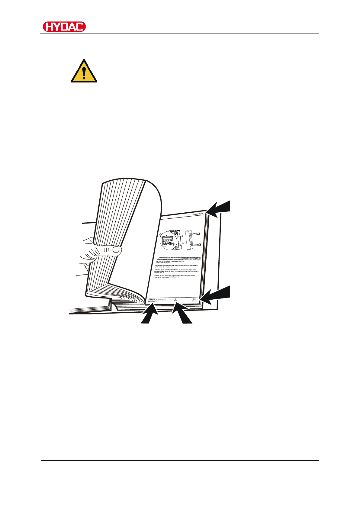
Note that the method described for locating specific information
these instructions prior to starting the unit up for the first time and
Chapter description
Page number
Document language
Documentation no.
Using the documentation
does not release you from your responsibility of carefully reading
at regular intervals in the future.
What do I want to know?
I determine which topic I am looking for.
WHERE can I find the information I’m looking for?
The documentation has a table of contents at the beginning. There, I select
the chapter I'm looking for and the corresponding page number.
Edition date
with index/
file name
The documentation number with its index enables you to order another copy
of the operating and maintenance instructions.
The index is incremented every time the manual is revised or changed.
OLFCM 15/30/45/60
en(us)
8 / 84
Page 9
Safety information
BeWa OLFCM 15-60 3595923a en-us 2018-06-28 .docx
2018-06-28
Safety informati on
The unit was built according to the statutory provisions valid at the time of
delivery and satisfies current safety requirements.
Any residual hazards are indicated by safety information and instructions and
are described in the operating instructions.
Observe all safety and warning instructions attached to the unit. They must
always be complete and legible.
Do not operate the unit unless all the safety devices are present.
Secure the hazardous areas which may arise between the unit and other
equipment.
Maintain the unit inspection intervals prescribed by law.
Document the results in an inspection certificate and keep it until the next
inspection.
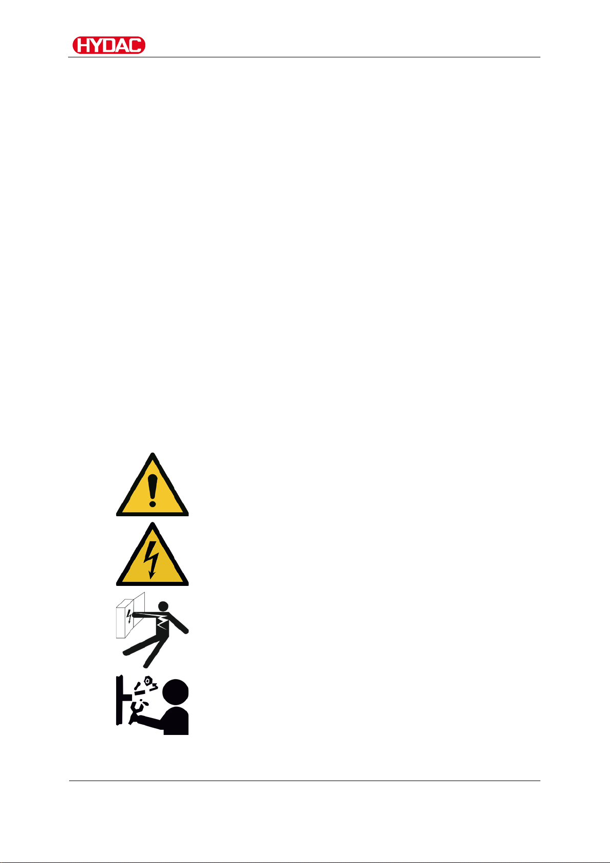
Hazard symbols
These symbols are listed for all safety information and instructions in these
operating instructions which indicate particular hazards to persons, property
or the environment.
Observe these instructions and act with particular caution in such cases.
Pass all safety information and instructions on to other users.
General hazard
Danger due to electrical voltage / current
Exposed electrical co mp on en ts
Danger of electrical shock
OLFCM 15/30/45/60
Danger due to operating pressure
en(us)
9 / 84
Page 10
Safety information
BeWa OLFCM 15-60 3595923a en-us 2018-06-28 .docx
2018-06-28
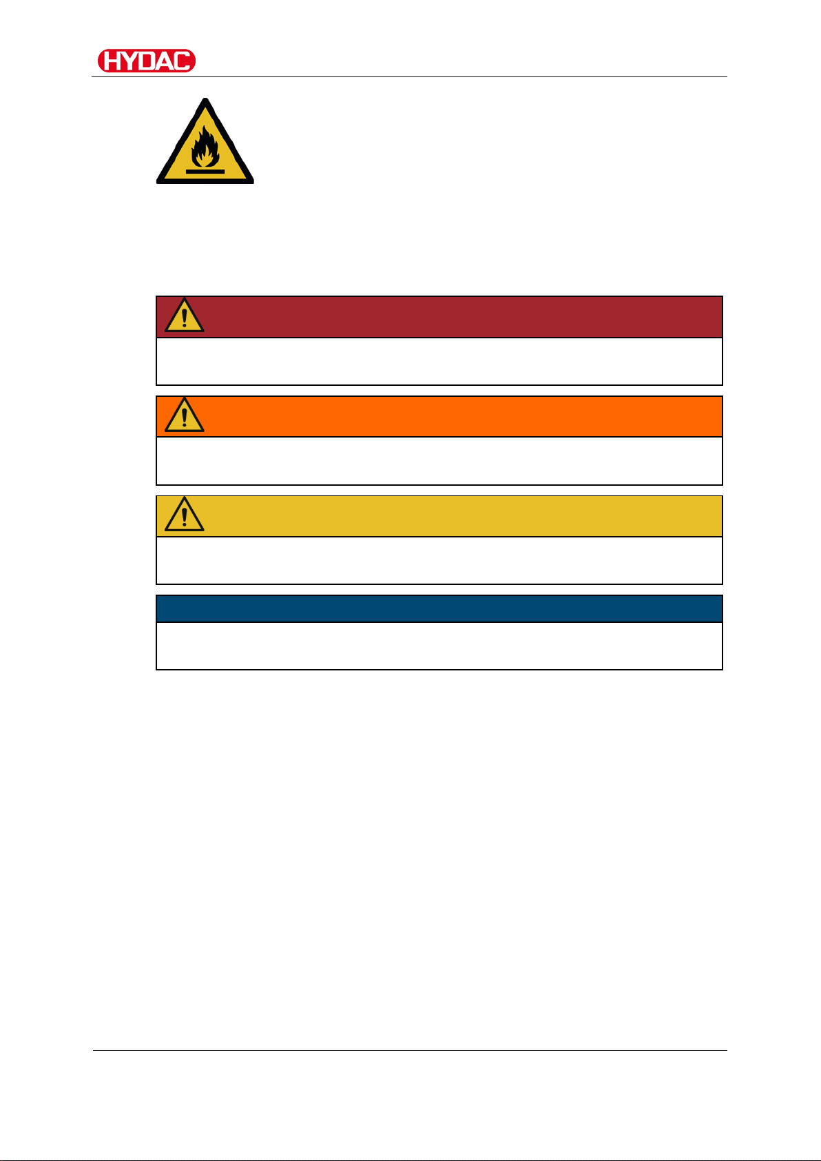
DANGER
DANGER – The signal word indicates a hazardous situation with a high level
WARNING
WARNING – The signal word indicates a hazardous situation with a medium
CAUTION
CAUTION – The signal word indicates a hazardous situation with a low level
NOTICE
NOTICE – The signal word indicates a hazardous situation with a high level
Warning of flammable substances
Signal words and their meaning in the safety information and instructions
In these instructions you will find the following signal words:
of risk, which, if not avoided, will result lethal or serious injury.
level of risk, which, if not avoided, can result lethal or serious injury.
of risk, which, if not avoided, can result in minor or moderate injury.
of risk, which, if not avoided, will result in damage to property.
OLFCM 15/30/45/60
en(us)
10 / 84
Page 11
Safety information
BeWa OLFCM 15-60 3595923a en-us 2018-06-28 .docx
2018-06-28
Structure of the safety information and instructions
All warning instructions in this manual are highlighted with pictograms and
signal words. The pictogram and the signal word indicate the severity of the
danger.
Warning instructions listed before an activity are laid out as follows :
HAZARD SYMBOL
SIGNAL WORD
Observe regulatory information
Observe the following regulatory information and guidelines:
• Legal and local regulations for accident prevention
• Legal and local regulat ions for environmental protectio n
• Country-specific regul a t ions , or g ani zation-specific regulations
Type and source of danger
Consequence of the danger
► Measures to avert danger
OLFCM 15/30/45/60
en(us)
11 / 84
Page 12
Safety information
BeWa OLFCM 15-60 3595923a en-us 2018-06-28 .docx
2018-06-28
Proper/Designated Use
Use the unit only for the application described in the following.
The OLF Compact is a stationary filter unit used for filtering hydraulic or
lubricating oils in bypass flow.
Proper or designated us e of the prod uc t extends to the following :
• observing all instructions contained in the instruction manual.
• performing inspectio n and maintenance work.
Depending on the version (see model code), you may use the OLF only in
connection with the following media:
WARNING
Fire hazard
Danger of bodily injury
► With the OLF, you may filter/pump only
media/fluids with a flash point ≥ 56°C/133°F
NOTICE
Unpermitted operating media
The filtration unit will be destroyed.
► The OLF is to be used only with mineral oils or mineral oil-based
raffinates.
► Do not filter any caustic or explosive media.
OLFCM 15/30/45/60
en(us)
12 / 84
Page 13
Safety information
BeWa OLFCM 15-60 3595923a en-us 2018-06-28 .docx
2018-06-28
Never operate the unit in potentially explosive
Improper Use or Use Deviating from Intended Use
DANGER
Danger due to unanticipated use of the unit
Bodily injury and damage to property will result
when operated improperly.
►
atmospheres.
► The unit is only to be used with permissible
media.
Any use extending beyond or deviating therefrom shall not be considered
intended use. HYDAC Filter Systems GmbH will assume no liability for any
damage resulting from such use. The user alone, shall assume any and all
associated risk
Improper use may result in hazards and/or will damage the unit. Examples of
improper use:
• Operation in potentially explosive atmospheres.
• Operation with a non-approved medium.
• Operation under non-approved operational conditions.
• Operation when the safety devices are defective.
• Modifications to the power unit made by the user or purchaser.
• Inadequate monitoring of parts that are subject to wear and tear
• Improperly performed repair work.
OLFCM 15/30/45/60
en(us)
13 / 84
Page 14

Safety information
BeWa OLFCM 15-60 3595923a en-us 2018-06-28 .docx
2018-06-28
Qualifications of personnel / target group
Persons who work on the power unit must be aware of the associated
hazards when using the power unit.
Auxiliary and specialist personnel must have read and understood the
operating instructions, in particular the safety information and instructions,
and applicable regulations before beginning work.
The operating instructions and applicable regulations are to kept so they are
accessible for operating and specialist personnel.
These operating instructions is intended for:
Auxiliary personnel: such persons have been instructed in power unit
operation and are aware of pote nti al haz ar ds due to i mproper use.
Specialist personnel : such persons with corresponding specialist training and
several years work experience. They are able to assess and perfor m the
work assigned to them, they are also able to recognize potential hazards.
OLFCM 15/30/45/60
en(us)
14 / 84
Page 15

Safety information
BeWa OLFCM 15-60 3595923a en-us 2018-06-28 .docx
2018-06-28
Activity
Personnel
Knowledge
Transport / storage
Forwarding agent
Proof of knowledge of
Hydraulic / electrical
Specialist personnel
Safe handling/use of
Operation,
Auxiliary personnel
Product-specific
Disposal
Specialist personnel
Proper and
installation,
first commissioning,
operation/settings
maintenance,
troubleshooting,
repair,
decommissioning,
disassembly
Specialist personnel
cargo securing
instructions
Safe handling/operat ion
of hoisting and lifting
equipment
tools
Fitting and connection
of hydraulic lines and
connections
Fitting and connection
of electrical lines,
electrical machinery,
sockets, etc.
Checking the phase
sequence
Product-specific
knowledge
Operations control
knowledge
Knowledge about how
to handle operating
media
environmentally-friendly
disposal of materials
and substances
Decontamination of
contaminants
Knowledge about reuse
OLFCM 15/30/45/60
en(us)
15 / 84
Page 16

Safety information
BeWa OLFCM 15-60 3595923a en-us 2018-06-28 .docx
2018-06-28
Wear suitable clothing
Loose-fitting clothing increases the risk of being caught or being drawn in on
rotating parts, and the risk of getting caught on protruding parts. You can be
severely injured or killed.
• Wear close-fitting clothing.
• Do not wear any rings, chains or any other jewelry.
• Wear work safety shoes.
Stoppage in an emergency (EMERGENCY STOP)
In case of emergency, switch off the power unit at the main switch.
OLFCM 15/30/45/60
en(us)
16 / 84
Page 17
Transporting the OLF
BeWa OLFCM 15-60 3595923a en-us 2018-06-28 .docx
2018-06-28
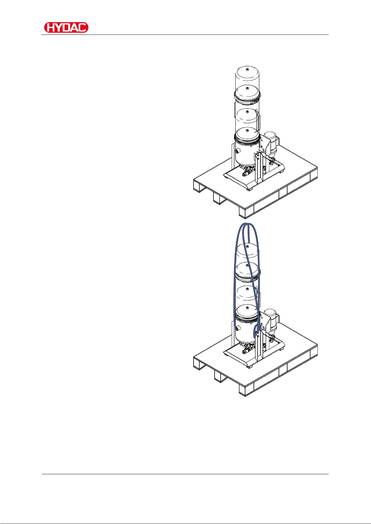
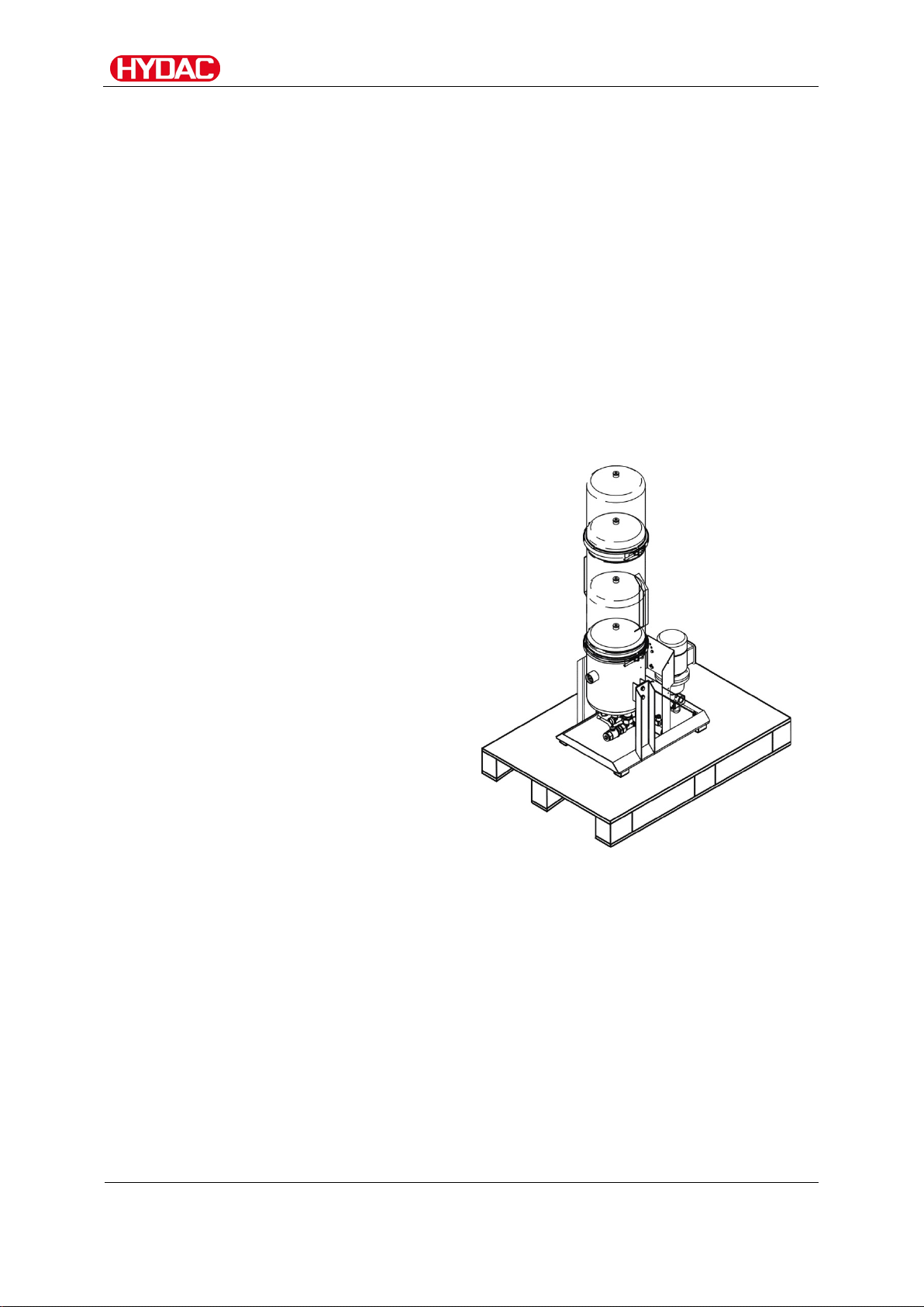
Transport the OLF in an upright
For transportation using a crane or
Transporting the OLF
position only.
forklift, use two slings at the
specified anchor points between
the filter housing and the base.
OLFCM 15/30/45/60
en(us)
17 / 84
Page 18
Storing the OLF
BeWa OLFCM 15-60 3595923a en-us 2018-06-28 .docx
2018-06-28
Storage temperature:
5 … 30°C / 41 … 86°F
Humidity:
up to 80% relative humidity, non-condensing
Air condition:
Clean, salt-free air, not near oxidizing substances
Storage duration:
Indefinite.
Store the OLF in an upright
Storing the OLF
Completely drain the OLF and remove all filter elements before putting into
storage.
position only.
(rust film).
Before the unit is started up again after being
stored for more than two years, all seals must be
replaced.
OLFCM 15/30/45/60
en(us)
18 / 84
Page 19

Checking the scope of delivery
BeWa OLFCM 15-60 3595923a en-us 2018-06-28 .docx
2018-06-28
Item
Qty.
Description
1 1 OffLine Filter 15/30/45/60
Operation and Maintenance Instructions OLFCM 15-60
- 1 Operating and maintenance instructions CS1000
- 1 Operating and maintenance instructions AS 1000 (optional)
- 1 Operating and maintenance instructions SMU1200 (optional)
Checking the scope of delivery
Upon receiving the OLF, check it for any damage in transit. Do not put the
OLF into operation unless it is in perfect condition. Any damage in transit is to
be reported to the forwarding agent or the department in charge immediately;
the unit may not be commissioned until this damage is properly remedied.
The following items are suppl ied:
- 1
(this document)
OLFCM 15/30/45/60
en(us)
19 / 84
Page 20

OLF Features
BeWa OLFCM 15-60 3595923a en-us 2018-06-28 .docx
2018-06-28
Differential pressur e at 15l/min.
Viscosity [mm²/s]
OLF Features
The filters of the OLF 15/30/45/60 series are sturdy filters for stationary
applications in hydraulic and lubrication systems with large volumes of fluid.
Features of the DIMICRON® filter elements used in thes e filter s ar e thei r
particularly high contamination retention capacity and an environmentally
safe method of disposal (incinerable).
The OLFCM has a vane pump and is suitable for operating fluids with a
viscosity of 15–200 mm²/s.
Pressure drop over DIMICRON® filter element(s)
Differential pressur e [bar]
The pressure loss through the filter housing is negligible.
OLFCM 15/30/45/60
en(us)
20 / 84
Page 21
OLFCM components
BeWa OLFCM 15-60 3595923a en-us 2018-06-28 .docx
2018-06-28
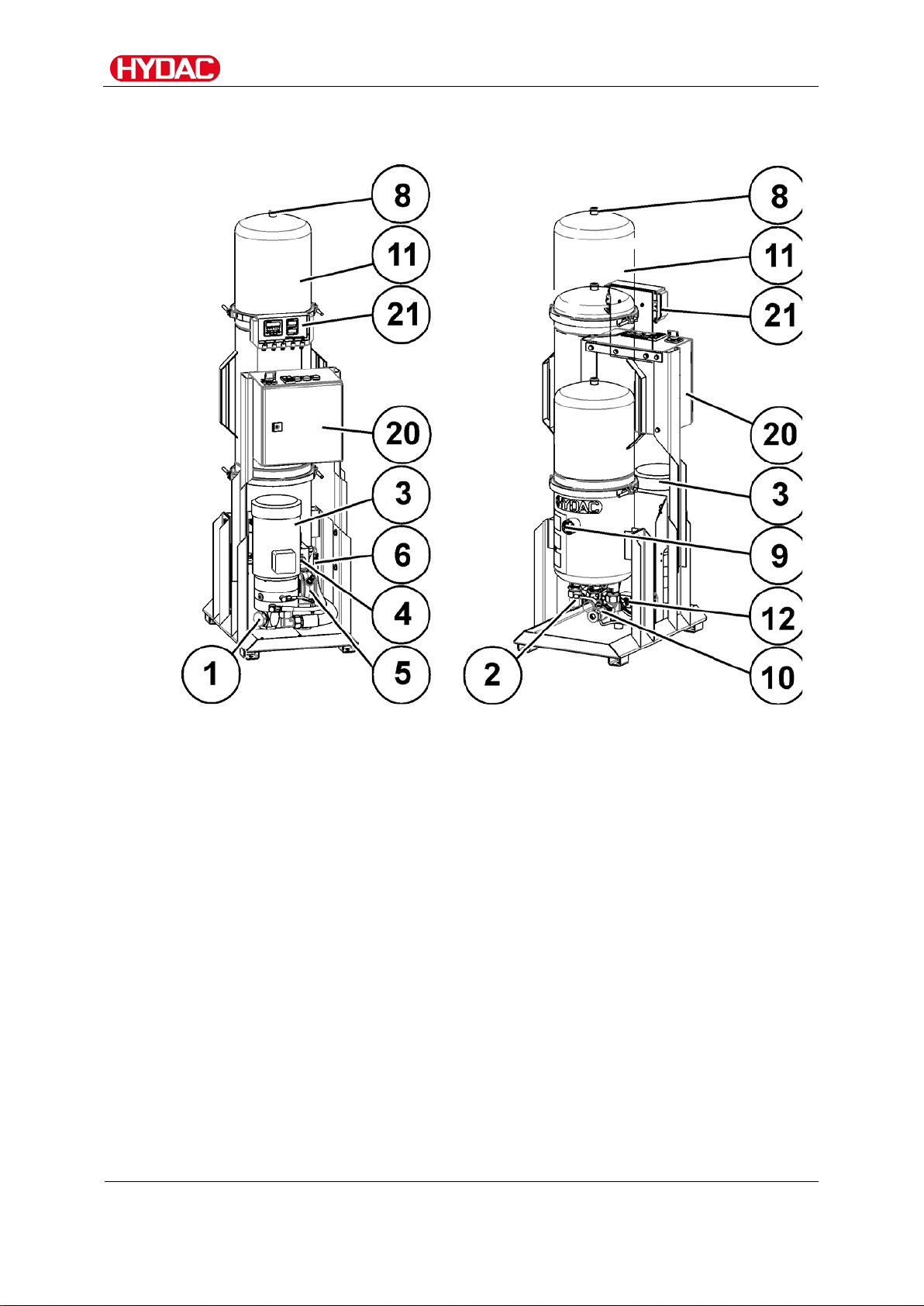
OLFCM components
OLFCM 15/30/45/60
en(us)
21 / 84
Page 22

OLFCM components
BeWa OLFCM 15-60 3595923a en-us 2018-06-28 .docx
2018-06-28
Item
Description
1
Inlet (IN)
2
Outlet (OUT)
3
Motor pump assembly
4
Protective screen
5
ContaminationSensor CS1000
6
AquaSensor AS1000 (optional)
8
Air bleed
9
Back-pressure indicator
10
Draining
11
Filter housing
12
Differential pressur e indicator (optional)
20
Switch cabinet (optional)
21
SensorMonitoring Unit (opt ional)
OLFCM 15/30/45/60
en(us)
22 / 84
Page 23
Dimensions
BeWa OLFCM 15-60 3595923a en-us 2018-06-28 .docx
2018-06-28
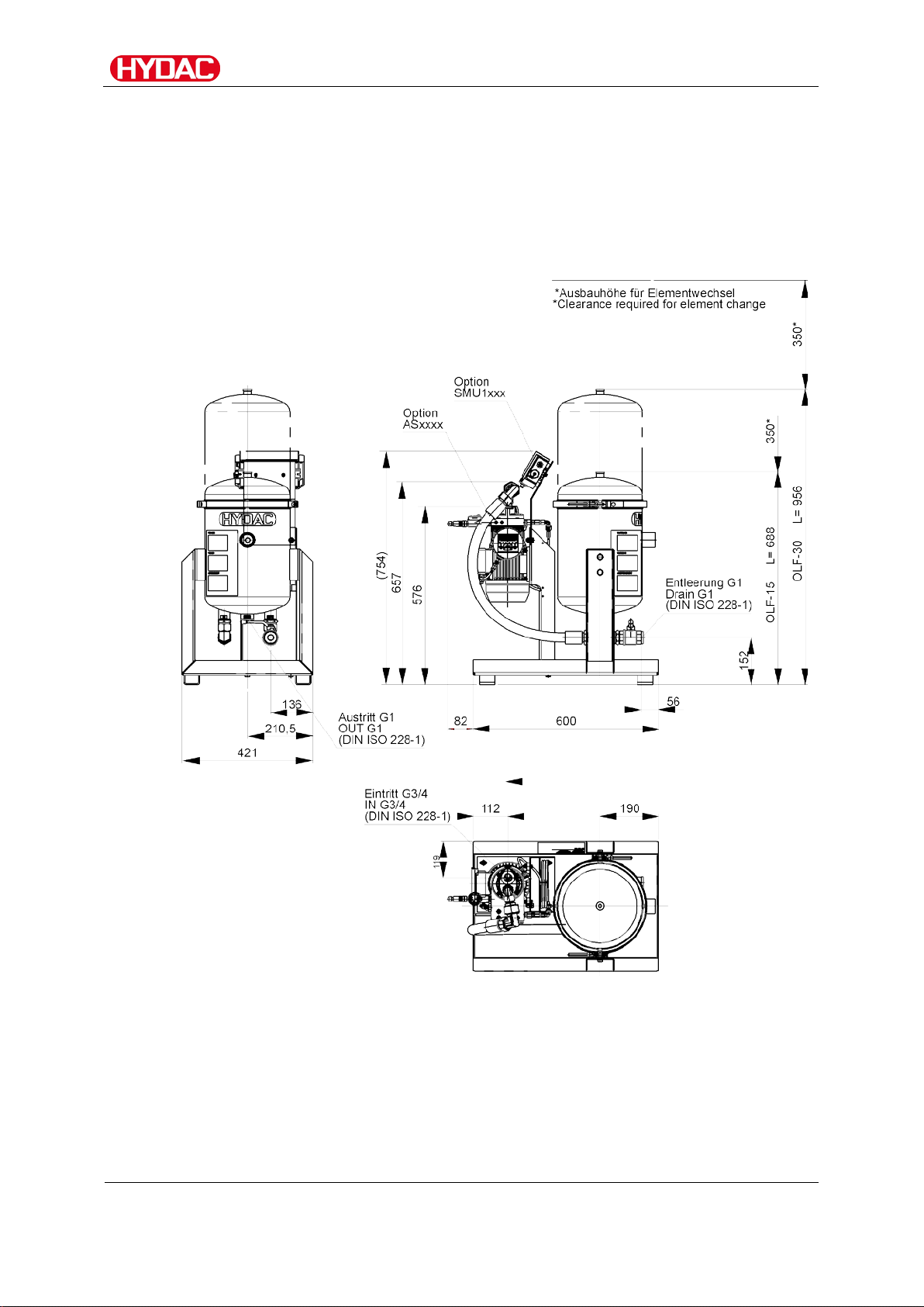
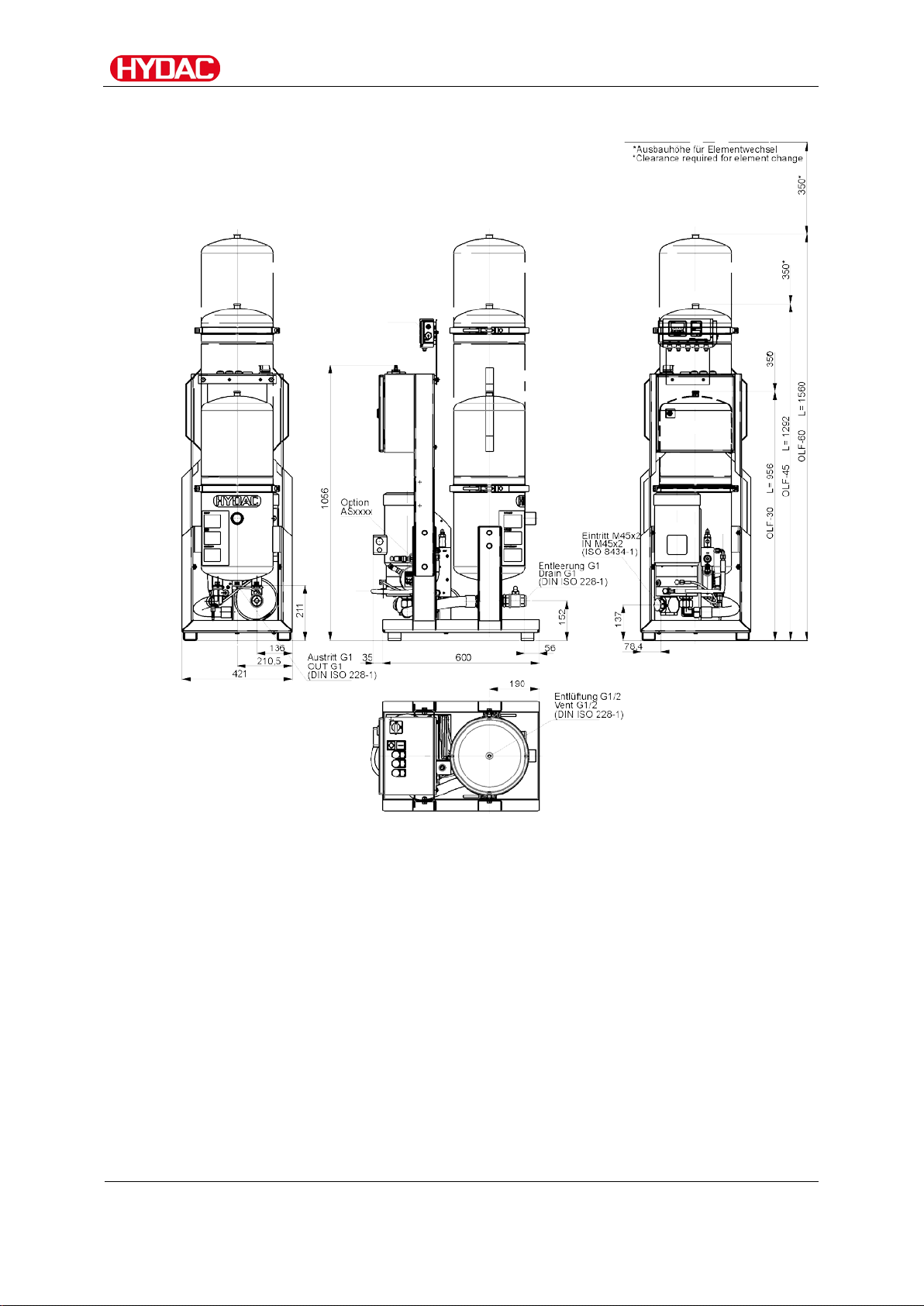
Dimensions
The filtration unit is available in different versions; below you will find an
overview with the corresponding dimensions.
Version OLF 15/15, 30/15
(All dimensions in mm)
OLFCM 15/30/45/60
en(us)
23 / 84
Page 24
Dimensions
BeWa OLFCM 15-60 3595923a en-us 2018-06-28 .docx
2018-06-28
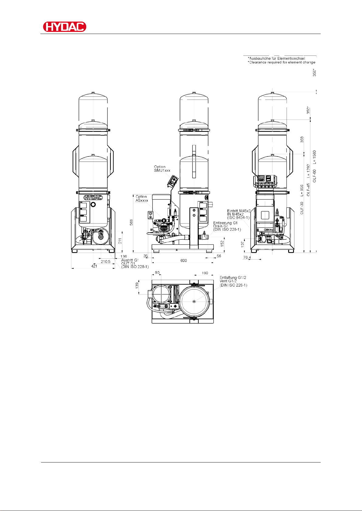
Version – OLF 30-60
(All dimensions in mm)
OLFCM 15/30/45/60
en(us)
24 / 84
Page 25
Dimensions
BeWa OLFCM 15-60 3595923a en-us 2018-06-28 .docx
2018-06-28
Version – OLF30-60 - FA
(All dimensions in mm)
OLFCM 15/30/45/60
en(us)
25 / 84
Page 26
Hydraulic diagram
BeWa OLFCM 15-60 3595923a en-us 2018-06-28 .docx
2018-06-28
M
CS
OUT
IN
AS
3
4
5
6
7
8
12
11
10
9
1
2
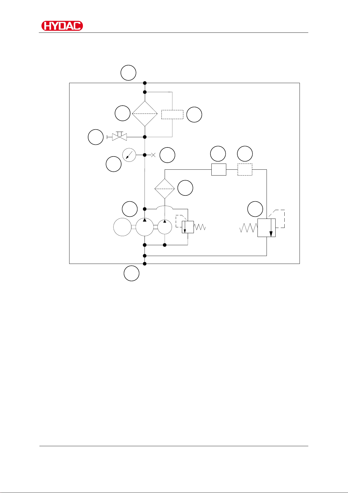
Hydraulic diagram
OLFCM 15/30/45/60
en(us)
26 / 84
Page 27

Hydraulic diagram
BeWa OLFCM 15-60 3595923a en-us 2018-06-28 .docx
2018-06-28
Item
Description
1
Inlet (IN)
2
Outlet (OUT)
3
Motor pump assembly
4
Protective screen
5
ContaminationSensor CS1000
6
AquaSensor AS1000 (optional)
7
Pressure control valve
8
Air bleed
9
Back-pressure indicator
10
Draining
11
Filter housing
12
Differential pressur e indicator (optional)
OLFCM 15/30/45/60
en(us)
27 / 84
Page 28

Setting up / installing the unit
BeWa OLFCM 15-60 3595923a en-us 2018-06-28 .docx
2018-06-28
1.
Set up the unit horizontally on a level surface.
2.
Fasten the unit with suitable floor anchors.
3.
Make sure that there is sufficient space above the filter housing to
4.
Observe the maximum permissible ambient temperature and constant
5.
In the case of installation below the fluid level, install shut-off valves in
6.
We recommend installing a dirt trap or suction strainer with ~250 µm in
Setting up / installing the unit
Observe the following points when setting up the unit:
replace the filter elements.
supply of cooling air to avoid overheating the motor/pump assembly.
the feed and return lines.
the supply line of the filtration unit.
Drilling template for floor anchors
(All dimensions in mm)
OLFCM 15/30/45/60
en(us)
28 / 84
Page 29

Setting up / installing the unit
BeWa OLFCM 15-60 3595923a en-us 2018-06-28 .docx
2018-06-28
Δp ~ 6,8 * L / d4 * Q * V * D
Δ
=
Pressure differential in [bar]
L = Pipe length [m]
d = Internal pipe diameter [mm]
Q = Flow rate [l/min]
V = Kinematic viscosity [mm²/s]
D = Density [kg/dm³]
Mineral oil-based hy dr aul ic fluid has a
Notes on pipes and hoses
Make sure that no vibrations or stress/loading from other machinery and
equipment are carried over to the filter housing. If necessary, use expansion
joints.
The pressure loss in a hydraulic line depends upon:
• Flow rate
• Kinematic viscosity
• Pipe dimensions
• fluid density
The pressure loss can be estimated for hydraulic oils as follows:
p
density of ~ 0.9 kg/dm³.
This applies to straight pipelines and hydraulic oils. Additional threaded
connections and pipe bends increase the pressure differential. Additional
threaded connections and pipe bends increase the pressure differential.
Keep the height difference between the pump and the oil level in the tank as
low as possible.
Constrictions in the connections and lines should be avoided. This could
compromise suction output and cause cavitation .
Take note that the nominal size of the connected hoses/piping must be at
least as large as the inlet port sizes.
Make sure that no vibrations or stresses are carried over to filtration unit
when connecting the piping. Make sure that no vibrations or stress/loading
from other machinery and equipment are carried over to filter unit. Use hoses
or expansion joints if necessary.
OLFCM 15/30/45/60
en(us)
29 / 84
Page 30

Setting up / installing the unit
BeWa OLFCM 15-60 3595923a en-us 2018-06-28 .docx
2018-06-28
Connecting the suction port
For the suction port connection, use a flexible hose that is resistant to
negative pressure. Avoid constrictions in the connecting lines, as they
compromise suction performance and increase the risk of cavitation.
In case of coarse contamination (> 100 µm) such as weld splatter, an
appropriate suction strainer must be installed in the suction line in order to
protect the pump.
Overpressure at the suction port connection
The filter unit will be damaged
► The maximum pressure on the suction port connection IN must not be
more than -0.4 to 0.6 bar.
NOTICE
Connecting the pressure port
Make sure that the nominal width of the pressure line corresponds to the
threaded connection of the filter housing.
Install the return line below the oil level to prevent air from entering the fluid
in the tank
If the clogging indicator pressure displayed for the a clean
filter element is > 1 bar, use a differential pressure clogging
indicator.
OLFCM 15/30/45/60
en(us)
30 / 84
Page 31

Setting up / installing the unit
BeWa OLFCM 15-60 3595923a en-us 2018-06-28 .docx
2018-06-28
Electrical connection of the unit
Exposed electrical co mponents in the switch
cabinet
Danger of fatal injury due to electric shock
► Any work involving the electrical system may
The electrical connection of units without connection plugs to the power
supply module may only be performed by a technician with corresponding
knowledge and skills.
DANGER
only be done by a properly trained, certified
electrician.
Compare the voltage and frequency specifications on the motor type label
with the existing network specifications.
Depending on the voltage supply, connect the electri c mot or of the pum p wi th
a Y or delta connection (see nameplate on the corresponding motor).
Star (Y-) connection Delta connection
OLFCM 15/30/45/60
en(us)
31 / 84
Page 32

Setting up / installing the unit
BeWa OLFCM 15-60 3595923a en-us 2018-06-28 .docx
2018-06-28
Check direction of rotation
Check the direction of rotation of the motor by switching it on briefly (jog
mode).
The unit requires a clockwise rotating field at the connecting socket.
Incorrect phase sequence / rotation direction of the motor
The pump will be destroyed.
► In jog mode, check the direction of rotation of the motors.
► A rotation direction arrow on the fan cover of the motor identifies the
correct direction of rotation.
If rotation is in the opposite direction, change the phases in the terminal box
or rotate the phases in the connection plug using the phase inverter in the
connection plug.
NOTICE
OLFCM 15/30/45/60
en(us)
32 / 84
Page 33

Setting up / installing the unit
BeWa OLFCM 15-60 3595923a en-us 2018-06-28 .docx
2018-06-28
- PKZ
FA0
FA1
FA2
FA3
The motor protection switch switches
Power supply for the installed
The differential pressure switch
The differential pressure switch
The differential pressure switch
Identifying electrical equipment
The unit is supplied with a variety of electrical equipment. Below you will find
the explanations of the abbreviations.
You can identify the electrical equipment using the type label.
off in case of electrical ov er l oad of
the filtration unit.
sensors
switches the filtration unit off when
the message "Filter clogged"
appears.
Neutral wire required.
switches the filtratio n unit off when
the message "Filter clogged"
appears.
No neutral wire required.
switches the filtratio n unit off when
the message "Filter clogged" or
"Target purity reached" appears.
No neutral wire required.
OLFCM 15/30/45/60
en(us)
33 / 84
Page 34

Setting up / installing the unit
BeWa OLFCM 15-60 3595923a en-us 2018-06-28 .docx
2018-06-28
Without electrical equipment
Install a suitable motor protection switch and connect the power supply to the
electric motor terminal box.
Connect the differential pressure sensor and forward the desired signals to
the control.
Supply the contamination sensors with the appropriate voltage and forward
the desired signals to the control.
PKZ – On/off switch with connection cable
Connect the power supply from the on/off switch to your network. If the builtin motor protection switch trips, the fault indicator lamp lights up.
Connect the differential pressure sensor and forward the desired signals to
the control.
Supply the contamination sensors with the appropriate voltage and forward
the desired signals to the control.
FA0 – Filter switch-off 0
Connect the power supply from the control cabinet to your network. If the
built-in motor protection switch trips, the fault indicator lamp lights up.
Connect the differential pressure sensor and forward the desired signals to
the control.
The contamination sensors are supplied with the appropriate voltage.
FA1 – Filter switch-off 1
Connect the power supply from the control cabinet to your network. If the
built-in motor protection switch trips, the fault indicator lamp lights up.
The differential pressure sensor switches the filtration unit off when the
message "Filter clogged" appears. The fault indicator lamp "Change oil filter"
lights up.
No neutral wire is required in the connecting line.
FA2 – Filter switch-off 2
Connect the power supply from the control cabinet to your network. If the
built-in motor protection switch trips, the fault indicator lamp lights up.
The differential pressure sensor switches the filtration unit off when the
message "Filter clogged" appears. The fault indicator lamp "Change oil filter"
lights up.
No neutral wire required.
OLFCM 15/30/45/60
en(us)
34 / 84
Page 35

Setting up / installing the unit
BeWa OLFCM 15-60 3595923a en-us 2018-06-28 .docx
2018-06-28
FA3 – Filter switch-off 3
Connect the power supply from the control cabinet to your network. If the
built-in motor protection switch trips, the fault indicator lamp lights up.
The differential pressure sensor switches the filtration unit off when the
message "Filter clogged" appears. The fault indicator lamp "Change oil filter"
lights up.
The ContaminationSensor monitors the contamination of the fluid and
switches the filtratio n u nit off at the set target purity .
OLFCM 15/30/45/60
en(us)
35 / 84
Page 36

Starting up the OLF
BeWa OLFCM 15-60 3595923a en-us 2018-06-28 .docx
2018-06-28
In the "PKZ" version , the unit has an
Starting up the OLF
WARNING
Hydraulic system is under pressure
6 bar maximum
87 psi max.
Danger of bodily injury
► Note the maximum operating pressure
► The hydraulic system must be depress ur ized
► Vent the filter housing
Before commissioning, open the filter housing and check that the filter
elements are firmly in place and that the locking cap is installed, or insert the
filter elements if necessary. You can find details about changing the filter
elements on page 52.
Put the OLF into operation only after all preparations for commissioning are
complete.
Operating elements - PKZ version
on/off switch with a motor protection
switch. Switch the pump on or off at
the on/off switch.
before performing any work on the hydraulic
system.
OLFCM 15/30/45/60
en(us)
36 / 84
Page 37

Starting up the OLF
BeWa OLFCM 15-60 3595923a en-us 2018-06-28 .docx
2018-06-28
Item
Description
Q1
Main switch
S1
On switch
S2
Stop switch
H1
Fault indicator lamp
H2
Fault indicator lamp "Replace filter eleme nts"
Operating elements – version FA1 / FA2
This version has the following operating elements on the switch box:
OLFCM 15/30/45/60
en(us)
37 / 84
Page 38

Starting up the OLF
BeWa OLFCM 15-60 3595923a en-us 2018-06-28 .docx
2018-06-28
Item
Description
Q1
Main switch
S1
On switch
S2
Stop switch
H1
Fault indicator lamp
H2
Fault indicator lamp "Replace filter eleme nts"
S3
Operating mode selector switch
Operating elements – version FA3
This version has the following operating elements on the switch box:
OLFCM 15/30/45/60
en(us)
38 / 84
Page 39

Starting up the OLF
BeWa OLFCM 15-60 3595923a en-us 2018-06-28 .docx
2018-06-28
1.
o.k.
2.
SWtOUT
o.k.
3.
o.k.
4.
TARGET
o.k.
5.
o.k.
6.
RSTART
o.k.
7.
Setting the target purity on the CS is complete.
Setting operating mode "Operation until target purity reached" on the CS
Turn the operating mode selector switch S3 to position "Operation until target
purity reached" and turn the unit on at on-switch S1.
To adjust the target purity of the CS, proceed as follows:
Press the
Scroll with the buttons until the display shows
confirm with the
Confirm the M4 display with the
Scroll with the buttons until the display shows
press the
button.
and
button.
button.
and
button.
Set the desired target puri ty with the buttons + and
confirm with the
Scroll with the buttons until the display shows
press the
button.
button.
and
OLFCM 15/30/45/60
en(us)
39 / 84
Page 40

Starting up the OLF
BeWa OLFCM 15-60 3595923a en-us 2018-06-28 .docx
2018-06-28
1.
o.k.
2.
SENS A
o.k.
2.
SWtOUT
o.k.
3.
o.k.
4.
TARGET
o.k.
5.
o.k.
6.
Esc
SAVE
o.k.
7.
Unplug the power supply / plug for the CS or SMU for 20 seconds
8.
Setting the target purity on the SMU is complete.
Setting operating mode "Operation until target purity reached" on the SMU.
Turn the operating mode selector switch S3 to position "Operation until target
purity reached" and turn the unit on at on-switch S1.
To adjust the target purity of the SMU, proceed as follows:
Press the
button.
Scroll with the buttons until the display shows
confirm with the
button.
Scroll with the buttons until the display shows
confirm with the
Confirm the M4 display with the
button.
button.
Scroll with the buttons until the display shows
press the
button.
Set the desired target puri ty with the buttons + and
confirm with the
Press the
with the
button.
button.
button three times until
appears and confirm
and then plug them in again.
and
and
and
Operational mode "Continuous operation"
Turn the operating mode selector switch S3 to position "Continuous
operation" and turn the unit on at on-switch S1.
OLFCM 15/30/45/60
en(us)
40 / 84
Page 41

Operating the ContaminationSensor (display is optional)
BeWa OLFCM 15-60 3595923a en-us 2018-06-28 .docx
2018-06-28
WAIT99
WAIT0
Item
LED
Designation
A
Status
B
Display
C
Measured
D
Service variable
E
Switch point 1
F
Switch point 2
Operating the ContaminationSensor (di splay is optional)
If the sensor is switched on or supplied with power, the display shows
HYDAC CS1000 in moving letters, then the firmware version is displayed for
2 seconds.
This is followed by a countdown:
…
.
The durat ion of the countdown corresponds to the set measurement time
MTIME. This means that the countdown runs from 99 ... 0 within the set
measurement time (factory setting = 60 sec).
OLFCM 15/30/45/60
variable
Status display
6-figure display with 17 segments each
Display of respective measured variable,
e.g: ISO / SAE / NAS
Display of respective service variable,
e.g.: Flow / Out / Drive / Temp
Indicates the status of the switching output. When
the LED is lit, the switching output is activated, i.e.
the switch is closed.
Reserved
en(us)
41 / 84
Page 42

Operating the ContaminationSensor (display is optional)
BeWa OLFCM 15-60 3595923a en-us 2018-06-28 .docx
2018-06-28
Key
Function
o.k.
You jump one menu level down.
Esc
You jump up one menu level.
o.k.
+
You scroll throug h the di spl ay
Function of the Keys
The following keys are available to you for operating and setting the C S1x2x.
You confirm a changed value at the lowest menu level.
You confirm at the top menu level to save or reject a
change in value.
In order to leave the menu without changing the values,
press the ESC key until SAVE appears in the display.
With the keys switch to CANCEL and confirm
with the
key or wait 30 seconds without pressing a
key.
You exit the menu without changing the values.
You change values / settings on the lowest menu level.
ISO / SAE/NAS / Flow / Out / Drive / Temp.
You move through the menu.
You select numbers.
Once the lowest menu level has been reached, the values in the display will
start to flash.
OLFCM 15/30/45/60
en(us)
42 / 84
Page 43

Operating the ContaminationSensor (display is optional)
BeWa OLFCM 15-60 3595923a en-us 2018-06-28 .docx
2018-06-28
Display
Designation
Display
Designation
Display
Designation
2=1(1%
A &1
15 1§2
Measured variables on the display
The measured variables give you information on the oil cleanliness in the
system.
You will gain a measured value with an accuracy of ± 1/2 ISO code wi thi n the
calibrated range.
ISO (Cleanliness class)
SAE (Cleanliness class)
Measured value ISO code
NAS (Cleanliness Class - only CS 13xx)
SAE class measurement cat eg or y
NAS class measurement categ or y
OLFCM 15/30/45/60
en(us)
43 / 84
Page 44

Operating the ContaminationSensor (display is optional)
BeWa OLFCM 15-60 3595923a en-us 2018-06-28 .docx
2018-06-28
Display
Designation
Display
Designation
Display
Designation
Display
Designation
1§8
60
2)5C
Service variables on the display
The service variables inform you about the current status in the
ContaminationSensor.
The service variables are not calibrated. They represent an approximate
value for installing the sensor in the hydraulic system.
Flow (flow rate)
Out (Analog output)
Flow rate in permissible range
Drive (performance of the LED)
Temp (Temperature)
Current or voltage output at the analog
output.
(example: 13.8 mA)
Performance (1-100%) of the LED in the
sensor.(example: 60%)
Fluid temperature in the sensor.
(example: 29.5 °C or 84.2 °F)
OLFCM 15/30/45/60
en(us)
44 / 84
Page 45

Operating the ContaminationSensor (display is optional)
BeWa OLFCM 15-60 3595923a en-us 2018-06-28 .docx
2018-06-28
Keys
The following appears in the
+
+
LOCK
UNLOCK
Activate / deactivate keypad lock.
Activate or deactivate the keypad lock by pressing both keys simultaneously
to prevent further input.
display (1 sec)
The display switches to the preset display after 1 second.
When the supply voltage to the CS is disconnected, the activated keypad
lock "LOCK" is unlocked and reset to "UNLOCK".
Designation
Activating key lock
Deactivating key lock
OLFCM 15/30/45/60
en(us)
45 / 84
Page 46

Operating the SensorMonitoring Unit SMU (optional)
BeWa OLFCM 15-60 3595923a en-us 2018-06-28 .docx
2018-06-28
2=1(1%
C
A
D
B
3/8
1)3
E
Item
LED
Description
A
Status
Status display
B
Display
Consists of a 6-digit display and shows the
C
Measured
This indicates which measurement is currently
D
Service variable
Indicates which service variable is shown in the
E
Unit (of
The units of the fluid temperature display can be
Operating the SensorMonitoring Unit SMU (optional)
If the SMU is powered up, then it can be used and parameters can be set,
even without any sensors being connected.
The saving of measurement data is accomplished after a minimum of one
sensor has been connected.
The individual controls and their operation are described in the following.
Display (CS1000 and AS1000)
variable
measurement)
Keyboard elements
The keyboard consists of six buttons. These buttons are used to operate the
SMU and to navigate through the menus (hierarchically structured).
selected measured values.
being shown in the display e.g. ISO / SAE/NAS.
display e.g. Flow / Drive.
set to °C or °F.
OLFCM 15/30/45/60
en(us)
46 / 84
Page 47

Operating the SensorMonitoring Unit SMU (optional)
BeWa OLFCM 15-60 3595923a en-us 2018-06-28 .docx
2018-06-28
Keyboard
Designation
o.k.
One level lower
Esc
One level higher
Scroll through display
Keys
The following appears in the
+
LOCK
+
UNLOCK
Confirmation of changed value (lowest level)
confirm when changes are to be saved or cancelled (top
level)
No value change
Change values at the lowest levels
(if you are at the lowest menu level, the display will flash)
Scroll through menu
Select numbers
Activating/deactivating key lock
Lock the keyboard to prevent unwanted / accidental entries or operation. To
activate or deactivate keypad locking, press both keys simultaneously.
display (1 sec)
Designation
Key Lock is activated
The display switches to the preset display after 1 second.
Key Lock is deactivated
OLFCM 15/30/45/60
en(us)
47 / 84
Page 48

Operating the SensorMonitoring Unit SMU (optional)
BeWa OLFCM 15-60 3595923a en-us 2018-06-28 .docx
2018-06-28
Keys
Display
Designation
o.k.
2=1(1%
3/8
1)3
Switching the display on and off
You can switch off the display. Only the status LED stays active on switched
off displays.
To switch off the display, press the two keys simultaneously.
Switching back on is accomplished by pressing any key.
Switches displays off
Esc
Switches displays on
OLFCM 15/30/45/60
en(us)
48 / 84
Page 49

Operating the SensorMonitoring Unit SMU (optional)
BeWa OLFCM 15-60 3595923a en-us 2018-06-28 .docx
2018-06-28
Display
Designation
2=1(1%
Display
Designation
&6A
ISO
Flow Out
TempDriveSAE/NAS
Display
Designation
15 1§2
Measured variables CS1000
The measurements provide you with information about the purity of the oil in
the system concerned. The measurement variables are calibrated. They
indicate a measured value with an accuracy of +/- 1/2 codes/class.
Measured variable "ISO"
Measured variable "SAE"
The measured value is updated
depending on the set measuring time.
Display of the 3-digit ISO code.
Measured variable "NAS"
The measured value is updated
depending on the set measuring time.
Display of a channel in the SAE class.
The measured value is updated
depending on the set measuring time.
Display of a channel in the NAS class.
OLFCM 15/30/45/60
en(us)
49 / 84
Page 50

Operating the SensorMonitoring Unit SMU (optional)
BeWa OLFCM 15-60 3595923a en-us 2018-06-28 .docx
2018-06-28
Display
Designation
108
Display
Designation
1§8
Display
Designation
42
Display
Designation
2)5C
Display of the media temperature
Service variables
These values give you information about the current flow and the LED
brightness within the CS1000 Sensor. The service variables are not
calibrated.
Service variable "Flow"
Service category "Out"
Here, you can see the averaged flow
through the ContaminationSensor unit
(e.g. 108 ml/min)
Service variable "Drive"
Service category "Temp"
Here you can see the value emitted as
analog output signal (example: 13.8 mA)
Display of the current LED brightness (1100%) in the ContaminationSensor
(example: 42%).
indirectly measured in the
ContaminationSensor. The display takes
place dependent on setting in °C or °F
(example: 29.5°C)
OLFCM 15/30/45/60
en(us)
50 / 84
Page 51

Performing Maintenance
BeWa OLFCM 15-60 3595923a en-us 2018-06-28 .docx
2018-06-28
Display
Designation
1)3
Display
Designation
3/8
AquaSensor AS1000 measured vari ables
Measured variable "Water saturation"
When using the AS, the measurement is
shown on the display as the relative
humidity of the operating fluid, expressed
as percentage saturation.
Measured variable "Temperature"
The AS continuously measures the fluid
temperature. Depending on the setting
under TP.UNIT, the measurement is
either shown in Celsius °C, or as
Fahrenheit °F.
Performing Mai ntenance
The OLF is standard-equipped with a dynamic pressure gauge. This displays
the pressure ahead of the filter ele men t.
Replace the filter elements immediately when the back pressure is > 2.5 bar
or when the indicator is in the red range.
Optionally, the OLF can also be supplied with electrical differential pressure
gauges.
WARNING
Hydraulic systems are under pressure
Danger of bodily injury
► The hydraulic system must be depress ur ized
before performing any work on the hydraulic
system.
OLFCM 15/30/45/60
en(us)
51 / 84
Page 52

Performing Maintenance
BeWa OLFCM 15-60 3595923a en-us 2018-06-28 .docx
2018-06-28
1.
Switch off the unit and make sure it cannot
2.
Close all shut-off valves at the inlet and
3.
Unscrew the air bleed screw (x) completely
4.
(1) Have a suitable drip tray on hand to
3.
Screw in the air bleed screw (x) by hand in a
Changing the filter element(s)
To change the filter elements, proceed as follows:
be inadvertently switched back on.
outlet.
using a 10 mm Allen wr ench.
catch the operating fluid.
(2) Open the drain fitting, and collect the
escaping fluid in the tray.
Once the housing has been completely
drained, close the drain fitting.
clockwise direction and tighten it firmly using
a 10 mm Allen wrench.
OLFCM 15/30/45/60
en(us)
52 / 84
Page 53

Performing Maintenance
BeWa OLFCM 15-60 3595923a en-us 2018-06-28 .docx
2018-06-28
4.
Release the housing tensioning clamps (1)
5.
Turn the element locking cap on the top filter
and remove them.
Remove the cover (a).
Remove the intermediate piece (b).
element by 90° in counterclockwise direction
(1) and lift off the locking cap (2).
OLFCM 15/30/45/60
en(us)
53 / 84
Page 54

Performing Maintenance
BeWa OLFCM 15-60 3595923a en-us 2018-06-28 .docx
2018-06-28
6.
Turn all filter elements 90° in a
7.
8.
Clean the inside of the filter housing of
counterclockwise direction, and remove
them.
in an environmentally friendly manner.
coarse dirt.
Check the O-rings on the filter housing for
damage. If necessary, replace them.
Dispose of the used filter eleme nt s
OLFCM 15/30/45/60
en(us)
54 / 84
Page 55

Performing Maintenance
BeWa OLFCM 15-60 3595923a en-us 2018-06-28 .docx
2018-06-28
9.
Insert the filter element into the bayonet
fitting (1), and lock it in place by turning each
10.
Place the element locking cap on the upper
individual filter element 90° in the clockwise
direction (2).
filter element (1).
Turn the locking cap 90° in the clockwise
direction to lock it in place.
No element locking cap = no
filtration.
OLFCM 15/30/45/60
en(us)
55 / 84
Page 56

Performing Maintenance
BeWa OLFCM 15-60 3595923a en-us 2018-06-28 .docx
2018-06-28
11.
Put the intermediate piece (b) on the lower
12.
Open all shut-off valves at the inlet and
13.
Fill the filter housing slowly.
14.
The filter element change is now complete.
section (c).
Mount the lower housing tensioning clamp
(1) and tighten it with a torque of 20 Nm.
Secure it using the lock nut.
Put the cover (a) on the intermediate piece
(b).
Mount the upper housing tensioning clamp
(2) and tighten it with a torque of 20 Nm.
Secure using the lock nut.
We recommend applying lubricant
containing a slip additive to the threads of
the housing tensioning clamp each time filter
elements are changed so that it remains
easy to remove.
Lubricant containing a slip additive - HYDAC
p/no..: 3066287
outlet.
Switch the unit on.
Slightly undo the air bleed screw (x). The air
in the filter housing can escape via the slot
on the air bleed screw.
Bleed the filter housing through the air bleed
screw (x) until operating fluid comes out.
Tighten the air bleed screw.
OLFCM 15/30/45/60
en(us)
56 / 84
Page 57

Performing Maintenance
BeWa OLFCM 15-60 3595923a en-us 2018-06-28 .docx
2018-06-28
10
20
20
30
40
Item
Description
10
Protective screen, 100 µm
20
O-ring
30
Screw connection
40
Screw connection
Exchanging the prefilter to the ContaminationSensor
NOTICE
Missing prefilter / operation without prefilter
The ContaminationSensor is blocked
► Never operate the unit without a prefilter
► Clean the prefilter regularly
A prefilter is installed to stop the ContaminationSensor from blockin g up.
Exchange the prefilter regularly depending on the contamination level of the
fluid.
OLFCM 15/30/45/60
en(us)
57 / 84
Page 58

Status messages – SMU1200 (optional)
BeWa OLFCM 15-60 3595923a en-us 2018-06-28 .docx
2018-06-28
LED
Display
Status
To do
Status
SMU
Check the power
SMU ready for
You can make further
0
NoSENS
A sensor is
Check sensor
NoSENS
No sensor is
Connect a sensor to
Status messages – SMU1200 (optional)
The SMU can take on the following status:
flashing code
-
Green
Red
no digits displayed
no function
operation
connected to sensor
interface A.
This is not
recognized.
supply to the SMU.
Contact the HYDAC
service department.
measurements.
interface A – is an
MCS1000 or a
CS1000 connected?
Check the connection
cables between the
sensor and the SMU.
Check the sensor bus
address. The bus
address must be
different to SENS B.
Switch the SMU off
and then on again.
-
3
OLFCM 15/30/45/60
Green
connected.
This display will go
out after 10
seconds.
en(us)
If the fault recurs,
contact HYDAC
service department.
sensor interface A.
Switch the SMU off
and then on again.
0
58 / 84
Page 59

Status messages – SMU1200 (optional)
BeWa OLFCM 15-60 3595923a en-us 2018-06-28 .docx
2018-06-28
ERROR
Sensor A is causing
Switch the SMU off.
ERROR
Sensor A is causing
Check sensor A (use
OUT
RNGE
AS1000 ≤ firmware
Wait for a few more
AS1000 ≥ firmware
Wait for a few more
Red
Red
Red
a moderate fault.
a major fault.
V2.04:
The senso r at
sensor interface B is
outside of the
measurement range.
V2.10:
If the error occurs
again, check sensor A
(use HNG 3000 as an
aid)
HMG3000 as an aid)
measurement cycles.
measurement cycles.
3
4
2
Green
The senso r at
sensor interface B is
outside of the
measurement range
or has a short circuit
at the sensor.
Dewater the fluid in
the saturated range.
Check the sensor
outside the fluid or
with the calibration
and adjustment set
(part no. 3122629)
2
OLFCM 15/30/45/60
en(us)
59 / 84
Page 60

Status messages – SMU1200 (optional)
BeWa OLFCM 15-60 3595923a en-us 2018-06-28 .docx
2018-06-28
No
SENS
A sensor is
Check sensor
No
SENS
No sensor is
Connect a sensor to
EROR
EROR
AS1000 ≥ firmware
Switch the SMU off
Red
Green
connected to sensor
interface B.
This is not
recognized.
connected.
This display will go
out after 10
seconds.
interface B – is an
AS1000 connected?
Check the connection
cables between the
sensor and the SMU.
Check the sensor bus
address. The bus
address must be
different to SENS A.
If the fault recurs,
contact HYDAC
service department.
sensor interface B.
Switch the SMU off
and then on again.
3
0
Red
V2.10:
The senso r at
sensor interface B is
causing a major
error.
and then on again.
If the fault recurs,
contact HYDAC
service department.
4
OLFCM 15/30/45/60
en(us)
60 / 84
Page 61

Status messages – SMU1200 (optional)
BeWa OLFCM 15-60 3595923a en-us 2018-06-28 .docx
2018-06-28
LED
Display
Status /
Status
NoLOG
No log files are stored in the
ERROR
SMU
The SMU has a moderate
ERROR
SMU
The SMU has a major fault.
Red
flashing code
To do
memory.
Possible cause:
Other or new sensors have
been connected
The parameters for
REC.MOD have been
changed
3
Delete the memory in the
PowerUp menu.
Back up the data in advance
using the USB memory stick.
When adju sting the
REC.MOD, one must take
into account the fact that this
will need to be reset before
saving.
Red
Red
fault.
Switch the SMU off and then
on again.
If the fault recurs, contact
HYDAC service department.
Contact HYDAC.
3
4
OLFCM 15/30/45/60
en(us)
61 / 84
Page 62

Status messages – CS1000 (optionally with display)
BeWa OLFCM 15-60 3595923a en-us 2018-06-28 .docx
2018-06-28
LED
Flash code /
Status
Remedy
Error
Analogue output
Switching output
Flow status on the
Status messages – CS1000 (optionally with display)
Status LED / Display
Gree
n
Gree
n
display
digital output
-
current value
mA / V*
Conductive
-
current value
mA / V*
Conductive
CS o.k. ---
The flow rate has
reached the upper
limit.
Reduce the flow
rate to prevent the
sensor from going
into the CHECK
error state.
no.
-
-
OLFCM 15/30/45/60
Gree
n
55
current value
mA / V*
Conductive
44
The flow rate has
reached the upper
permissible range.
en(us)
Check the flow rate
in short cycles.
The sensor is in
the upper
permissible flow
rate range.
-
62 / 84
Page 63

Status messages – CS1000 (optionally with display)
BeWa OLFCM 15-60 3595923a en-us 2018-06-28 .docx
2018-06-28
LED
Flash code /
Status
Remedy
Analogue output
Switching output
Flow status on the
Error
no.
display
digital output
Gree
n
Gree
n
current value
mA / V*
Conductive
33
current value
mA / V*
Conductive
22
The flow rate is in
the middle
permissible range.
The flow rate has
reached the lower
permissible range.
Do nothing. The
sensor is in the
middle flow rate
range.
Check the flow rate
in short cycles.
The sensor is in
the lower
permissible flow
rate range.
-
-
Gree
n
current value
mA / V*
Conductive
OLFCM 15/30/45/60
11
The flow rate has
reached the lower
limit.
en(us)
Increase the flow
rate to prevent the
sensor from going
into the CHECK
error state.
-
63 / 84
Page 64

Status messages – CS1000 (optionally with display)
BeWa OLFCM 15-60 3595923a en-us 2018-06-28 .docx
2018-06-28
LED
Flash code /
Status
Remedy
Analogue output
Switching output
Flow status on the
<)<(</
2CLEAN
Error
no.
display
digital output
The sensor is
Red
below its
measurement
---
-
range ISO 9/8/7
current value
mA / V*
Conductive
-1
OLFCM 15/30/45/60
en(us)
64 / 84
Page 65

Status messages – CS1000 (optionally with display)
BeWa OLFCM 15-60 3595923a en-us 2018-06-28 .docx
2018-06-28
LED
Flash code /
Status
To do
Error
Analogue output
Switching output
Flow status on the
below
CHECK
2%2$2§
2DIRTY
Error
Red
display
digital output
- mA / - V
open
-1
It is not possible to
determine the flow
rate.
The sensor status
is undefined.
Check that the flow
is between 30 …
500 ml/min.
If the fluid
cleanliness is
the measurement
limit (ISO 9/8/7), it
may take several
measurement
cycles until
measured values
are displayed.
no.
3
Red
19.9 mA / 9.95 V*
open
-1
The sensor is
above its
measurement
range
ISO 25/24/23.
It is not possible to
determine the flow
rate.
Filter the fluid.
3
OLFCM 15/30/45/60
en(us)
65 / 84
Page 66

Status messages – CS1000 (optionally with display)
BeWa OLFCM 15-60 3595923a en-us 2018-06-28 .docx
2018-06-28
LED
Flash code /
CS1000 Status
To do
Error
Analogue output
Switching output
Flow status on the
Exceptions Errors
OFF
Red
display
digital output
0 mA / 0 V*
open
-
-
4.1 mA / 2.05 V*
CS
no display
no function.
Firmware error
Check the supply
voltage for the CS.
Contact HYDAC.
Reset the unit. (To
do this, disconnect
the CS from the
voltage supply) or
contact HYDAC.
no.
-
-1…-19
Red
open
-
-
4.1 mA / 2.05 V*
open
-
Communication
error
Check the wiring.
-20…-39
OLFCM 15/30/45/60
en(us)
66 / 84
Page 67

Status messages – CS1000 (optionally with display)
BeWa OLFCM 15-60 3595923a en-us 2018-06-28 .docx
2018-06-28
LED
Flash code /
CS1000 Status
To do
Analogue output
Switching output
Flow status on the
Error
no.
display
digital output
Red
Red
Red
-
4.1 mA / 2.05 V*
open
-
-
4.1 mA / 2.05 V*
open
-
-
4.1 mA / 2.05 V*
open
-
System error
Error during
automatic
adjustment
Error measuring
cell LED
Reset the unit. (To
do this, disconnect
the CS from the
voltage supply) or
contact HYDAC.
Reset the unit. (To
do this, disconnect
the CS from the
voltage supply)
/ check the flow
rate or contact
HYDAC.
Reset the unit. (To
do this, disconnect
the CS from the
voltage supply)
/ check the flow
rate or contact
HYDAC.
-40…-69
-70
-100
* Is not valid for HDA 5500 output signal
OLFCM 15/30/45/60
en(us)
67 / 84
Page 68

Errors and troubleshooting
BeWa OLFCM 15-60 3595923a en-us 2018-06-28 .docx
2018-06-28
Error
Cause(s)
Remedy
No oil flow
Pump transf ers in
Make sure that the pump is
Screw connection
Retighten the screw
Strainer in the
Check or clean the suction
Suction hose bent /
Check the suction hose for
Air in suction area
Fill the pump via the suction
The viscosity of the
Check the viscosity of the
Motor without
Check the supply line to the
Motor / pump
Contact HYDAC.
Change oil filter
Medium heavily
Replace the filter element s.
The viscosity of the
Check the viscosity of the
No supply voltage
Check the supply voltage.
Errors and troubleshooting
the wrong direction
of suction pipe
untight
suction pipe dirty
defective
and pump
fluid is too high
functioning in the direction
shown by the arrows on the
housing. If necessary, switch
two phases in the motor
control box.
connection on the hose
coupling.
strainer.
freedom of passage. Replace
it if necessary.
hose / hose coupling.
medium.
Heat the medium to reach the
permissible viscosity.
(Clogging indicator
appears)
OLFCM 15/30/45/60
voltage
defective
contaminated
Filter element
lifetime is exceeded
fluid is too high
available
en(us)
filtration unit. Replace it if
necessary.
medium.
Heat the medium to reach the
permissible viscosity.
68 / 84
Page 69

Errors and troubleshooting
BeWa OLFCM 15-60 3595923a en-us 2018-06-28 .docx
2018-06-28
Error
Cause(s)
Remedy
Running noise of
cavitation due to
Clean the suction strainer.
2=2=19
The pump is
Push the suction hose deeper
The pump is
Check the screwed fitting for
Air is drawn into the
The pressure hose or the
The viscosity of the
Check the viscosity.
The volumetric flow
Remove the CS and blow it
The CS does not
Check the pump for proper
The CS is blocked.
Remove the CS and blow it
The pump is not
There is no oil in
Fill the pump via the suction
CHECK
CHECK
motor-pump assembly
becomes substantially
louder.
blocked strainer in
the suction pipe.
sucking in air. The
suction hose is
positioned above
the oil level.
sucking in air.
tank.
fluid to be
conveyed is too
high.
into the tank, beneath the oil
level.
leaks.
pressure lance is positioned
about the level of the oil. Dip
the pressure lance into the oil.
sucking or sucking
badly.
over the CS is too
low.
The CS or the
prefilter is blocked.
recognize flow.
the pump.
out using compresse d air
against the direction of flow.
Check the prefilter to the CS.
Clean or replace the prefilter.
functioning.
Switch the unit on.
out using compressed air
against the direction of flow.
hose.
OLFCM 15/30/45/60
en(us)
69 / 84
Page 70

Disposal of OLF
BeWa OLFCM 15-60 3595923a en-us 2018-06-28 .docx
2018-06-28
1.
Switch the unit off.
2.
Close all shut-off valves on the unit.
3.
Drain the unit completely.
4.
Remove all the filter elements.
5.
Clean the inside of the filter housing.
6.
Remove all the hydraulic and electrical connections to the unit.
Disposal of OLF
To take the OLF out of operation, proceed as follows:
Disposing of the OLF
Dispose of the packaging material in an environmentally-friendly manner.
After dismantling the unit and separating the various materials, dispose of the
unit in an environmentally friendly manner.
OLFCM 15/30/45/60
en(us)
70 / 84
Page 71

Spare Parts List
BeWa OLFCM 15-60 3595923a en-us 2018-06-28 .docx
2018-06-28
Spare Parts List
Use only original spare parts. Make sure to always indicate the exact unit
designation (see nameplate) and the serial number when ordering spare
parts.
OLFCM 15/30/45/60
en(us)
71 / 84
Page 72

Spare Parts List
BeWa OLFCM 15-60 3595923a en-us 2018-06-28 .docx
2018-06-28
OLFCM 15/30/45/60
en(us)
72 / 84
Page 73

Spare Parts List
BeWa OLFCM 15-60 3595923a en-us 2018-06-28 .docx
2018-06-28
Item
Description
Part no.
Qty.
15
30
45
60 1 Foot
3030479
1 1 1 1 2
Lower section
3076290
1 1 1 1 3
Intermediate piece
3030463
- - 1 1 4
Cover, tall
3030461
- 1 - 1 5
Cover, flat
3030462
1 - 1 - 6
Filter element locking cap
0349235
1 1 1
1
7
Tensioning clamp for the
6 bar / 87 psi
6005235
1 1 2
2
8
O-ring for housing
NBR
6005449
1 1 2 2 8
O-ring for housing
FKM
6012630
1 1 2 2 9
Air bleed plug [Air bleed]
0403302
1 1 1 1 10
Filter element 2 µm
N15DM002
1251590
1 2 3 4 10
Filter element 5 µm
N15DM005
3252552
1 2 3 4 10
Filter element 10 µm
N15DM010
3115180
1 2 3 4 10
Filter element 20 µm
N15DM020
0349576
1 2 3 4 10
Filter element 30 µm
N15DM030
3048790
1 2 3 4 11
Dynamic pressure gauge
0036198
1 1 1
1
12
Clogging indicator /
* - - -
13
Vane pump with motor
* - - - - -
SMU1200
*
-
CS1000
*
-
See pos. 10,
3536729
1 1 1
1
filter housing
differential pressure
gauge
SensorMonitoring Unit
Contamination Sensor
Prefilter set, consisting of
10 pieces, strainer insert
*) available on request
OLFCM 15/30/45/60
page 74
en(us)
73 / 84
Page 74

Spare Parts List
BeWa OLFCM 15-60 3595923a en-us 2018-06-28 .docx
2018-06-28
10
20
20
30
40
Item
Qty
Part no.
Description
10 1 3536729
Prefilter set, consisting of 10 pieces
20 2 607770
o-ring (6.07 x 1.78 NBR 70 Shore)
30 1 6009078
Screw connection
40 1 618595
Screw connection
Prefilter to the ContaminationSensor
OLFCM 15/30/45/60
en(us)
74 / 84
Page 75

Technical Data
BeWa OLFCM 15-60 3595923a en-us 2018-06-28 .docx
2018-06-28
1000
30,20,10,2
>
β
barp 2=∆
Technical Data
Technical Data OLF-15 OLF-30 OLF-45 OLF-60
Number of filter elements
N15DMxxx
Contamination retention capacity
according to ISO 4572
Filtration performance data in line
with ISO 4572
Permissible p∆ on the element
Weight of the filter elements 3 kg 6 kg 9 kg 12 kg
Filter housing material Stainless steel: 1.4301
Filter housing volume 20 liter 40 liter 60 liter 78 liter
Operating pressure, maximum 6 bar /
Material of seals on filter housing NBR / FKM NBR / FKM NBR / FKM NBR / FKM
Empty weight ~ 40 kg ~ 60 kg ~ 70 kg ~ 90 kg
Permissible operating
temperature
1 2 3 4
500 g 1000 g 1500 g 2000 g
at
4 bar 4 bar 4 bar 4 bar
6 bar /
87 psi
10 … 80°C /
50 … 176°F
87 psi
10 … 80°C /
50 … 176°F
6 bar /
87 psi
10 … 80°C /
50 … 176°F
6 bar /
87 psi
10 … 80°C /
50 … 176°F
Motor-pump group 15 l/min 30 l/min 45 l/min 60 l/min
Operating pressure of the pumpe
in bar
Viscosity range in mm²/s 15 … 200 15 … 200 15 … 200 15 … 200
Engine power 370 W 1500 W 1500 W 1500 W
Material of seals in pump NBR NBR NBR NBR
Inlet connection, vane pump G ¾ M45 / G 1¼ M45 / G 1¼ M45 / G 1¼
Permissible operating
temperature
IP class
4.5 … 5.5 4.5 … 5.5 4.5 … 5.5 4.5 … 5.5
-10 … 40°C /
14 … 104°F
IP54 IP54 IP54 IP54
-10 … 40°C /
14 … 104°F
-10 … 40°C /
14 … 104°F
-10 … 40°C /
14 … 104°F
OLFCM 15/30/45/60
en(us)
75 / 84
Page 76

Model Code
BeWa OLFCM 15-60 3595923a en-us 2018-06-28 .docx
2018-06-28
OLF
-
30/15
- S -
N60
-
N15DM0020
- E -
PKZ-V
Basic type
Filter Size
Pump
S = Vane pump
Voltage
Filter element
Clogging indicator
Supplementary details
Model Code
OLFCM = Stationary with
ConditionMonitoring
15/… = 1 Filter element
30/… = 2 Filter element
45/… = 3 Filter element
60/… = 4 Filter element
…/xx = See "Nominal flow rate" table
B = P = 480 V, 3 Ph
C = P = 380 V, 3 Ph
G = P = 440 V, 3 Ph
L = P = 115 V, 1 Ph
M = 230 V, 1 Ph*
N = P = 400 V, 3 Ph
O = P = 460 V, 3 Ph
P = P = 575 V, 3 Ph
R = 415V, 3 Ph
S = P = 500 V, 3 Ph
W = P = 230 V, 3 Ph
X = other voltages on request
L60 /M60 = Operation at 60 Hz
N15DM002 = DIMICRON® 2 µm absolute
N15DM005 = DIMICRON® 5 µm absolute
N15DM010 = DIMICRON® 10 µm absolute
N15DM020 = DIMICRON® 20 µm absolute
N15DM030 = DIMICRON® 30 µm absolute
Z = without filter element
E = Standard, back pressure gauge
B = Differential pressure indicator - visual
C = Differential pressure gauge - electrical
D3 = Differential press ure gauge, visual/electrical (VM 2 D.0/-L220)
D4 = Differential pressure gauge, visual/electrical (VM 2 D.0/-24)
D5 = Differential pressure indicator, visual/electrical (VM 2 LZ.1/-DB)
F = Pressure switch, electrical (VR 2 F.0)
PKZ = with On / Off switch and motor protection switch
FA0 = On/off switch with cut-out when filter clogged including PKZ
(clogging indicator C or D3)
FA1 = On/off switch with cut-out when filter clogged including PKZ
(clogging indicator C or D3)
FA2 = On/off switch with cut-out when filter clogged including PKZ
(clogging indicator C) without neutral wire
FA3 = On/off switch with cut-out when filter clogged including PKZ
(clogging indicator C or D3) without neutral wire
V =
Seal material FKM (FPM, Viton®)
OLFCM 15/30/45/60
en(us)
76 / 84
Page 77

Model Code
BeWa OLFCM 15-60 3595923a en-us 2018-06-28 .docx
2018-06-28
15 l/min
30 l/min
45 l/min
60 l/min
15/15
- - -
30/15
30/30
- - 45/15
45/30
60/45
-
60/15
60/30
60/45
60/60
Nominal flow rate
- = not available
OLFCM 15/30/45/60
en(us)
77 / 84
Page 78

Index
BeWa OLFCM 15-60 3595923a en-us 2018-06-28 .docx
2018-06-28
Index
A
Analogue output ....................................... 62, 65, 66
AquaSensor .............................................. 22, 27, 51
Auxiliary personnel ......................................... 14, 15
C
Cause ................................................................... 68
Changing the filter element ................................... 52
Cleanliness ........................................................... 43
Clogging indicator ..................................... 68, 73, 76
Communication error ............................................ 66
connecting .......................................... 29, 30, 32, 34
Contamination class ............................................. 43
Contamination classes ......................................... 43
Contamination retention capacity ......................... 75
ContaminationSensor .. 22, 27, 35, 41, 44, 50, 57, 74
D
Density ................................................................. 29
Description............. 19, 22, 27, 37, 38, 46, 57, 73, 74
Differential pressure ........................... 20, 22, 27, 76
Differential pressure gauge .................................. 76
Differential pressure indicator ................... 22, 27, 76
Dimensions ........................................................... 23
DIMICRON ..................................................... 20, 76
Display ....... 41, 43, 44, 46, 48, 49, 50, 51, 58, 61, 62
Disposal .......................................................... 15, 70
Documentation Representative .............................. 2
E
H
Hazard symbol ................................................. 9, 11
HDA ...................................................................... 67
Hydraulic diagram................................................. 26
I
Imprint .................................................................... 2
IN 22, 27, 30
In case of emergency ........................................... 16
Inlet........................................................... 22, 27, 75
installing ......................................................... 28, 44
Internal pipe diameter ........................................... 29
IP class ................................................................. 75
ISO .............................. 41, 42, 43, 46, 49, 64, 65, 75
K
Key Lock ............................................................... 47
Keyboard ........................................................ 46, 47
M
Main switch ..................................................... 37, 38
Maintenance ............................................... 1, 19, 51
Measured value .................................................... 43
Measured variable ......................... 41, 43, 46, 49, 51
Measures .............................................................. 11
measuring ....................................................... 49, 67
Mineral oil ............................................................. 29
MTIME .................................................................. 41
Empty weight ........................................................ 75
Error ............................................. 62, 65, 66, 67, 68
F
Fault indicator lamp ........................................ 37, 38
Features ............................................................... 20
Filter .......... 13, 22, 27, 33, 34, 35, 65, 68, 73, 75, 76
Filter element ............................................ 68, 73, 76
Filter housing volume ........................................... 75
filtration .................. 12, 23, 28, 29, 33, 34, 35, 55, 68
Filtration ................................................................ 75
Firmware .............................................................. 66
Flash code ................................................ 62, 65, 66
Flow rate ......................................................... 29, 44
Flow status ............................................... 62, 65, 66
Forwarding agent .................................................. 15
Function of the Keys ............................................. 42
OLFCM 15/30/45/60
N
NAS ............................................... 41, 42, 43, 46, 49
O
OFF ...................................................................... 66
Off switch .............................................................. 76
OffLine Filter ..................................................... 1, 19
On switch ........................................................ 37, 38
operating .. 7, 8, 9, 12, 14, 15, 20, 36, 37, 38, 39, 40,
Operating elements .................................. 36, 37, 38
Operation ................................. 13, 15, 19, 39, 40, 76
Out.......................................................41, 42, 44, 50
OUT ................................................................ 22, 27
Outlet .............................................................. 22, 27
en(us)
42, 51, 52, 56, 75
78 / 84
Page 79

Index
BeWa OLFCM 15-60 3595923a en-us 2018-06-28 .docx
2018-06-28
P
Pressure differential .............................................. 29
Pressure drop ....................................................... 20
Proper/Designated Use ........................................ 12
Publisher ................................................................ 2
Pump .............................................................. 68, 76
R
Remedy .......................................................... 62, 68
RSTART ............................................................... 39
S
SAE .............................................. 41, 42, 43, 46, 49
select ................................................................ 8, 42
Sensor ...................................................... 50, 59, 73
Service ............................................... 41, 44, 46, 50
Service variable .................................. 41, 44, 46, 50
setting ........................................... 28, 41, 42, 50, 51
Signal word ..................................................... 10, 11
signal words.................................................... 10, 11
Size ...................................................................... 76
Specialist personnel ....................................... 14, 15
Status message .............................................. 58, 62
Suction hose ......................................................... 68
Switching output ....................................... 62, 65, 66
System error ......................................................... 67
T
TARGET ......................................................... 39, 40
Temperature ................................................... 44, 51
Transport ........................................................ 15, 17
U
USB ...................................................................... 61
V
Vane pump ..................................................... 73, 76
Viscosity ......................................................... 20, 75
W
Weight .................................................................. 75
OLFCM 15/30/45/60
en(us)
79 / 84
Page 80

Page 81

Page 82

Page 83

Page 84

HYDAC FILTER SYSTEMS GMBH
Industriegebiet Postfach 1251
66280 Sulzbach/Saar 66273 Sulzbach/Saar
Germany Germany
Phone: +49 (0) 6897 509 01 Central
Fax: +49 (0) 6897 509 846 Technical Department
Fax: +49 (0) 6897 509 577 Sales Department
Internet: www.hydac.com
Email: filtersystems@hydac.com
 Loading...