

Page 1

ISO 9001
QUALITÄT
MIT SYSTEM
Elektronischer
Druckschalter
Electronic
Pressure Switch
Manocontacteur
électronique
EDS 1700
Page 2

D
2
Page 3

Inhalt
1. Funktionen des EDS 1700
2. Montage
3. Bedienelemente der Folientastatur
4. Digitalanzeige
5. Ausgangsverhalten
5.1. RELAISAUSGÄNGE
5.2. ANALOGAUSGANG
5.3. EINSTELLEN DER SCHALTPUNKTE
UND RÜCKSCHALTPUNKTE/HYSTERESEN
5.3.1 Einstellen eines Schaltpunktes
5.3.2 Einstellen einer Hysterese
5.3.3 Einstellen eines Rückschaltpunktes
6. Maximalwert
6.1. ANSEHEN DES MAX-WERTES
6.2. RÜCKSETZEN DES MAX-WERTES
7. Grundeinstellungen
7.1. ÄNDERN DER GRUNDEINSTELLUNGEN
7.2. ÜBERSICHT DER GRUNDEINSTELLUNGEN
8. Programmierfreigaben
8.1. ÄNDERN DER SOFTWAREPROGRAMMIERFREIGABE
8.2. ÄNDERN DER HARDWAREPROGRAMMIERFREIGABEN
9. Ändern der Einbaulage
10. Fehlermeldungen
11. Technische Daten
12. Anschlußbelegung
13. Bestellangaben
14. Zubehör
14.1. MITGELIEFERTES ZUBEHÖR
14.2. SONSTIGES ZUBEHÖR
15. Geräteabmessungen
D
3
Page 4

1. Funktionen des EDS 1700
l Meßwertanzeige des aktuellen Druckes in bar, psi oder einem frei
D
skalierbaren Bereich.
l Schalten der 4 Relaisausgänge entsprechend dem Druck und den
eingestellten Schaltpunkten und Hysteresen bzw. Rückschaltpunkten.
l Erfassen des maximalen Druckes seit Einschalten des Gerätes.
l Menü zur Grundeinstellung (Anpassen des EDS 1700 an die jeweiligen
Applikation).
l Programmierfreigaben.
l Ändern der Einbaulage (Druckanschluß von oben oder unten).
2. Montage
Die Montage des EDS 1700 erfolgt über die 4 Befestigungsbohrungen in der
Gehäuserückwand. Der Druckanschluß ist zur mechanischen Entkopplung
über Minimessleitung vorzunehmen.
In kritischen Anwendungsfällen (z. B. starke Vibrationen oder Schläge) ist der
EDS 1700 auf Gummipuffern (DIN Schwingmetalle) zu montieren. Hierzu
bieten wir einen Montagesatz an (siehe "sonstiges Zubehör"). Eine direkte
Montage des EDS 1700 mit starrer Verrohrung ist nicht zulässig.
Im Auslieferzustand ist der Druckanschluß von unten und der elektrische
Anschluß von oben zugänglich. Die Gerätefrontplatte kann um 180° gedreht
werden, so daß der elektrische Anschluß von unten und der Druckanschluß
von oben erfolgen kann.
Der elektrische Anschluß ist von einem Fachmann nach den jeweiligen
Landesvorschriften durchzuführen (VDE 0100 in Deutschland). Für den
Anschluß des Analogausgangs sind grundsätzlich Leitungen mit Schirm zu
verwenden (z.B. LIYCY 4 x 0,5 mm²). Das Druckschaltergehäuse ist über
-Anschluß (neben der Klemmleiste) zu erden.
den
Zusätzliche Montagehinweise, die erfahrungsgemäß den Einfluß
elektromagnetischer Störungen reduzieren:
l Möglichst kurze Leitungsverbindungen herstellen.
l Leitungen mit Schirm verwenden.
l Der Kabelschirm ist in Abhängigkeit der Umgebungsbedingungen
fachmännisch und zum Zweck der Störunterdrückung einzusetzen.
l Direkte Nähe zu Verbindungsleitungen von Leistungsverbrauchern oder
störenden Elektro- oder Elektronikgeräten ist möglichst zu vermeiden.
4
Page 5

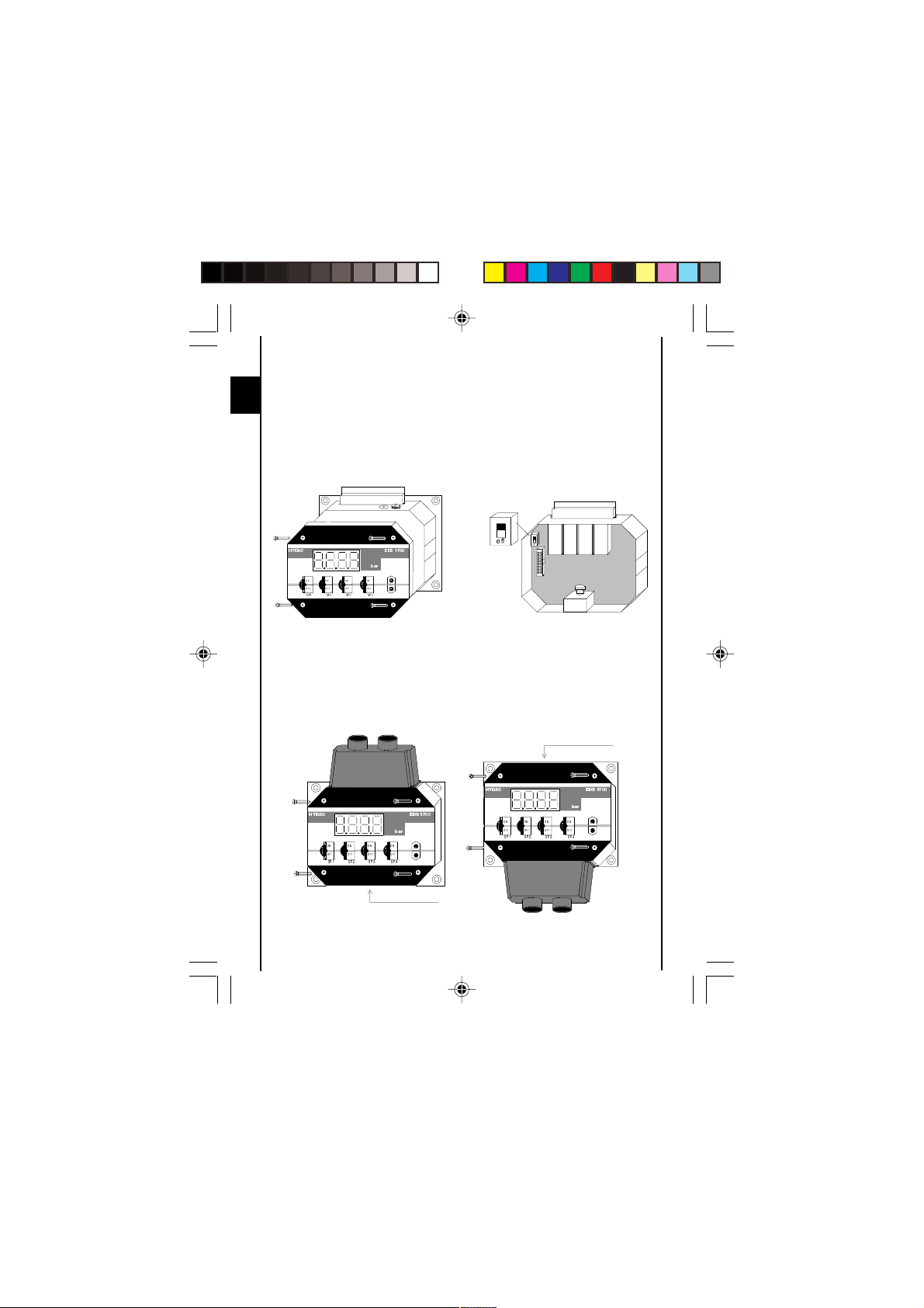
3. Bedienelemente der Folientastatur
Schrauben zum Entfernen
des Bedienteils
4-stellige
Digitalanzeige
Tasten zur Einstellung der
Schaltpunkte und Zusatzfunktionen
4. Digitalanzeige
Nach Einschalten der Versorgungsspannung zeigt das Gerät kurz "EdS" an
und beginnt mit der Anzeige des aktuellen Druckes.
2 s
Hinweise:
l In den Grundeinstellungen kann die Anzeige derart geändert werden, daß
das Gerät nach Einschalten permanent einen Schaltpunkt oder den
Maximalwert anzeigt. In diesem Fall erscheint nach der Einschaltmeldung
kurz "S.P. 1", "S.P. 2", "S.P. 3", "S.P. 4", oder "MAX".in der Anzeige.
Der aktuelle Druck kann dann kurzzeitig zur Anzeige gebracht werden,
indem die Taste "+" oder "-" betätigt wird.
l Übersteigt der aktuelle Druck den Nenndruck des Gerätes, so kann er nicht
mehr angezeigt werden und die Anzeige beginnt zu blinken.
l Liegt der aktuelle Druck unterhalb 0,5% des Nennbereiches, so wird 0
angezeigt.
D
5
Page 6
5. Ausgangsverhalten
B
5.1. RELAISAUSGÄNGE
D
Der EDS 1700 besitzt 4 Relaisausgänge. Zu jedem Relais kann ein
Schaltpunkt und ein Rückschaltpunkt bzw. eine Hysterese eingestellt werden.
Das jeweilige Relais zieht an wenn der eingestellte Schaltpunkt erreicht wurde
und fällt ab wenn der Rückschaltpunkt unterschritten wurde.
In den Grundeinstellungen (siehe Kapitel 7) wird durch den "Rückschaltmodus"
festgelegt, ob das Gerät mit einstellbaren Hysteresen oder einstellbaren
Rückschaltpunkten arbeitet.
Rückschaltmodus ist auf "Hysterese" gesetzt:
Die eingestellte Hysterese bestimmt den Rückschaltpunkt (Rückschaltpunkt =
Schaltpunkt minus Hysterese).
Rückschaltmodus ist auf "Rückschaltpunkt" gesetzt:
Der Rückschaltpunkt wird direkt eingestellt.
Abkürzungen: "S.P.1", .. "S.P.4" = Schaltpunkte 1..4
5.2. ANALOGAUSGANG
Analogausgangssignal 4..20 mA oder 0..10 V
(Einstellbar im Menü "Grundeinstellungen")
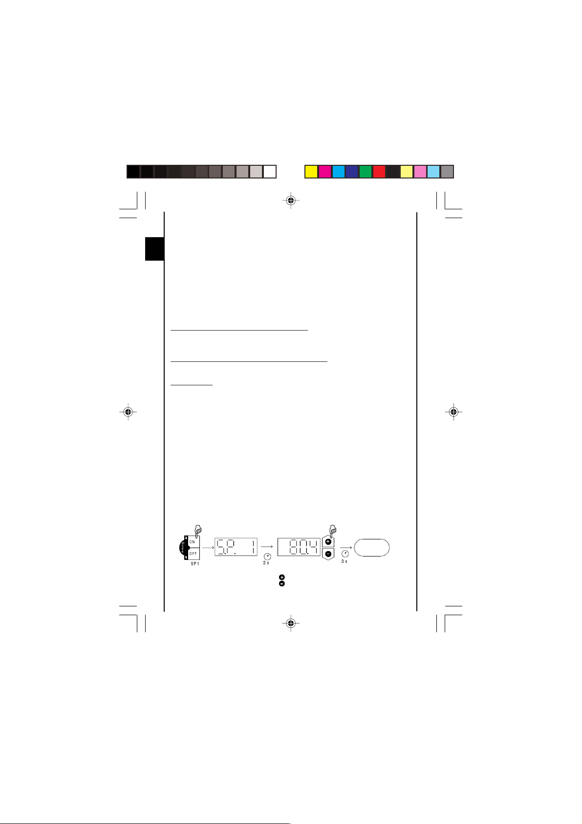
5.3. EINSTELLEN DER SCHALTPUNKTE UND
RÜCKSCHALTPUNKTE / HYSTERESEN
l Entsprechende Taste betätigen
l Schaltpunkt-/Rückschaltpunkt-/Hysteresenummer wird angezeigt
z.B. "S.P. 1"
l Nach 2 Sekunden blinkt die aktuelle Einstellung.
l Mit den Tasten "+" und "-" die Einstellung ändern.
l Nach 3 Sekunden schaltet die Anzeige zurück.
5.3.1 Einstellen eines Schaltpunktes
"H.Y.1", .. "H.Y.4" = Hysteresen 1..4
"r.S.P.1", .. "r.S.P.4" = Rückschaltpunkte 1..4
HH
21
P
R
G
H
2))
63
Taste ON
betätigen
Anzeige Schaltpunkt einstellen
6
V
= Wert größer
= Wert kleiner
V
Druckanzeige
Page 7

5.3.2 Einstellen einer Hysterese
G
(Nur möglich wenn der Rückschaltmodus auf "Hysterese" gesetzt ist.)
H
21
P
R
G
H
2))
G
Taste OFF
betätigen
63
V
Anzeige Hysterese einstellen
= Wert größer
= Wert kleiner
B
V
Druckanzeige
5.3.3 Einstellen eines Rückschaltpunktes
(Nur möglich wenn der Rückschaltmodus auf "Rückschaltpunkt" gesetzt ist.)
H
21
P
R
G
H
2))
Taste OFF
betätigen
63
V
Anzeige Rückschaltpunkt einstellen
= Wert größer
= Wert kleiner
B
V
Druckanzeige
Hinweise:
l Erscheint beim Einstellversuch "LOC" in der Anzeige ist die Programmierung
gesperrt.
Abhilfe: Hard- und Softwareprogrammierfreigabe auf "ON" setzen.
(siehe Kapitel 8 "Programmierfreigaben")
l Wird beim Ändern die Taste "+" oder "-" festgehalten, wird der Wert
automatisch mit einer größeren Schrittweite weitergezählt.
l Wenn eine Einstellung geändert wurde, erscheint beim Umschalten der
Anzeige kurz "PROG" in der Anzeige. Die neue Einstellung wurde dann im
Gerät gespeichert.
D
7
Page 8

6. Maximalwert
G
H
H
Der Maximalwert ist der höchste Druckwert, der seit Einschalten des Gerätes
D
oder seit dem letzten Rücksetzvorgang aufgetreten ist.
6.1. ANSEHEN DES MAX-WERTES
21
P
D
[
2))
63
Tasten ON und
OFF von Schaltpunkt 4 gleichzeitig betätigen
Anzeige Maximalwert wird
V
angezeigt
6.2. RÜCKSETZEN DES MAX-WERTES
21
U
H
V
H
W
2))
63
G
Tasten ON und
OFF von Schaltpunkt 3 gleichzeitig betätigen
Anzeige Maximalwert wird
Druckanzeige
V
angezeigt
Druckanzeige
V
8
Page 9

7. Grundeinstellungen
H
H
Zur Anpassung an die jeweilige Applikation kann das Verhalten des EDS 1700
über mehrere Grundeinstellungen verändert werden. Diese sind zu einem
Menü zusammengefaßt.
7.1. ÄNDERN DER GRUNDEINSTELLUNGEN
H
21
P
R
G
H
2))
63
G
Tasten ON und
OFF von Schaltpunkt 1 gleichzeitig betätigen
Anzeige Mit einzelner Taste Menüpunkt
21
P
R
G
H
2))
V
63
auswählen. (ON für nächsten,
OFF für vorherigen Menüpunkt.
V
Einstellung ändern danach
nächsten Menüpunkt auswählen.
Beenden des Grundeinstellungsmenüs:
Den Menüpunkt END anwählen, die Einstellung auf YES stellen, der EDS 1700
kehrt nach 2s in den normalen Anzeigemodus zurück.
Oder:
Tasten ON und OFF von Schaltpunkt 1 gleichzeitig betätigen, es wird END
angezeigt, der EDS 1700 kehrt nach 2s in den normalen Anzeigemodus
zurück.
Hinweise:
l Wird anstatt "MENU" "HIDE" angezeigt, kann das Menü nur aufgerufen
werden, indem die Tasten bereits beim Anlegen der Versorgungsspannung
betätigt sind (siehe Kapitel "Übersicht der Grundeinstellungen, Verstecktes
Grundeinstellungsmenü").
l Bei Änderung des Anzeigebereiches werden die Schaltpunkt und Hysterese
bzw. Rückschaltpunkteinstellungen automatisch umgerechnet. Dabei können
geringfügige Rundungsfehler entstehen.
l Erfolgt 50 Sekunden lang keine Tastenbetätigung wird das Menü
automatisch beendet, ohne daß eventuelle Änderungen wirksam werden.
B
D
9
Page 10

7.2. ÜBERSICHT DER GRUNDEINSTELLUNGEN
D
Einstellung Anzeige Einstell- Vorein-
Schaltrichtung Relais 1 (Relais 1) ON/OFF ON
"ON": Der jeweilige Relais wird beim
Erreichen des Schaltpunktes
aktiviert und beim Unterschreiten
des Rückschaltpunktes wieder
deaktiviert.
"OFF": Der jeweilige Relais ist im Ruhe-
zustand (0 bar) aktiviert und wird
beim Erreichen des Schaltpunktes
deaktiviert.
Einschaltverzögerung Relais 1 0.00..90s 0.01
(T
1)
on
Zeitdauer in Sekunden, die der jeweilige
Schaltpunkt erreicht oder überschritten
sein muß damit ein Schaltvorgang erfolgt.
Abschaltverzögerung Relais 1 0.00..90s 0.01
(T
1)
off
Zeitdauer in Sekunden, die der jeweilige
Rückschaltpunkt unterschritten sein muß
damit ein Schaltvorgang erfolgt.
Relais 2..4 wie oben
Rückschaltmodus (Switch Mode) R.S.P./ HYST.
"R.S.P": Der EDS 1700 arbeitet mit ein- HYST.
"HYST": Der EDS 1700 arbeitet mit ein-
(siehe auch Kapitel 5.1. "Relaisausgänge")
stellbaren Rückschaltpunkten.
stellbaren Hysteresen.
bereich stellung
10
Page 11

Einstellung Anzeige Einstell- Vorein-
bereich stellung
Primäranzeige (Primär) ACT/ ACT.
Anzeigewert der permanent in der Anzeige S.P.1..
stehen soll: S.P.4/
"ACT.": aktueller Druck MAX
"S.P.1" .. "S.P.4": Schaltpunkt 1 .. 4
"MAX": Maximalwert
Anzeigefilter (Display) SLOW/ MED.
"SLOW": Anzeige reagiert träge auf MED./
Druckschwankungen. FAST
"MED.": Anzeige reagiert normal auf
Druckschwankungen.
"FAST": Anzeige reagiert schnell auf
Druckschwankungen.
Festlegung des Anzeigebereiches BAR/ BAR
(RANGE) PSI/
"BAR": Der Druck wird in bar angezeigt. FREE
"PSI": Der Druck wird in PSI angezeigt.
"FREE": Der Anzeigebereich kann frei
skaliert werden. Wird diese Einstellung gewählt, müssen noch
Kommastelle sowie oberer und
unterer Anzeigebereich eingestellt werden.
(siehe folgende Parameter)
Beispiel: Wird der Anzeigebereich auf 0..215.5 verändert,
entspricht der Anzeigewert
215.5 dem Nenndruck des
Gerätes.
Anwendung: Anzeige anderer
dem Druckproportionaler Einheiten
z.B.KN, Kg, ...
D
11
Page 12

Einstellung Anzeige Einstell- Vorein-
D
Anzeige der Einheit (Unit) YES/NO NO
(nur bei Einstellung "RANG" = "BAR"
oder "PSI")
Bei Einstellung "YES" wird während der
Druckanzeige alle 7 Sekunden kurzzeitig die
eingestellte Einheit angezeigt.
Kommastelle (Point) 0 .. 0.0
(nur bei Einstellung "RANG" = "FREE") 0.000
Anzahl der Nachkommastellen, die der
EDS 1700 anzeigt.
Unterer Anzeigebereich (Range Low) -995 .. 0.0
(nur bei Einstellung "RANG" = "FREE") 9995
Untere Anzeigebereichsgrenz
Oberer Anzeigebereich (Range High) -995 .. Meßbe-
(nur bei Einstellung "RANG" = "FREE") 9995 reichsObere Anzeigebereichsgrenze endwert
Kalibrierung Sensornullpunkt (Calibrate) YES/NO ON
"YES": Der momentane Druck wird als
neuer Nullpunkt gespeichert.
Dies ist im Bereich +/- 3% des
Gerätenenndruckes möglich.
In der Anzeige erscheint "NEW"
wenn ein Abgleich im erlaubten
Bereich durchgeführt wurde,
ansonsten wird "Err" angezeigt.
Diese Funktion findet z.B. Anwendung wenn
im System immer ein Restdruck verbleibt,
der aber als 0 bar angezeigt werden soll.
Achtung:
Nach einem Nullpunktabgleich wird z. B. bei
einem 600 bar Gerät ein Druck von bis zu
18 bar als 0 bar angezeigt. Vor Arbeiten an
der Hydraulikanlage muß sichergestellt
werden, daß diese drucklos ist.
bereich stellung
12
Page 13

Einstellung Anzeige Einstell- Vorein-
B
Analogausgang (Output) MAMP/ VOLT
"MAMP": Der Analogausgang liefert VOLT
ein 4 .. 20 mA Signal.
"VOLT": Der Analogausgang liefert
ein 0 .. 10 V Signal.
Verstecktes Grundeinstellungsmenü YES/NO NO
(Hide)
"YES": Das Grundeinstellungsmenü
ist versteckt und kann nur noch
erreicht werden, indem bereits
beim Anlegen der Versorgungsspannung die Tasten für den
Menüaufruf betätigt sind.
Versionsnummer (Version)
Anzeige der aktuellen Softwareversion.
(Nur zum Ansehen)
Beenden der Grundeinstellung (End) YES/NO NO
bereich stellung
8. Programmierfreigaben
Das Gerät verfügt über 2 Programmierfreigaben die beide erteilt sein müssen
um Einstellungen zu ändern. Die Software-Programmierfreigabe kann während
des Betriebes gesetzt bzw. aufgehoben werden. Sie bietet Schutz vor
unbeabsichtigten Änderungen. Ein Sperren der Programmierung über die
Hardware-Programmierfreigabe bewirkt, daß während des Betriebes keine
Änderung der Einstellungen vorgenommen werden kann. Dies dient z.B. als
Sicherheitsfunktion oder als Schutz vor unerlaubten Änderungen.
8.1. ÄNDERN DER SOFTWARE-PROGRAMMIERFREIGABE
D
H
B
V
G
Beide Tasten gleichzeitig betätigen
und 3s festhalten.
H
Druckanzeige
V
Anzeige Mit einzelner Taste Einstellung ändern:
ON = Programmierung frei
OFF = Programmierung gesperrt
3 s
13
Page 14
8.2. ÄNDERN DER HARDWARE-PROGRAMMIERFREIGABE
l Gerät von der Versorgungsspannung trennen.
D
l Die 4 Schrauben der Gerätefrontplatte entfernen (Bild 1).
l Frontplatte vorsichtig abheben und zur Seite legen.
l Schiebeschalter auf der unteren Platine in die gewünschte Position schalten
(Bild 2): "OFF": Programmierung gesperrt
l Frontplatte wieder im Gehäuse einsetzen und anschrauben, dabei auf die
richtige Lage der in der Frontplatte befindlichen Dichtung achten.
Programmierung
frei
+<'$& ('6
EDU
21
21
U
P
H
R
V
G
H
H
W
2))
2))
63
63
21
21
P
D
[
B
2))
2))
63
63
gesperrt
RII
off
Bild 1
9. Ändern der Einbaulage
l Gerät von der Versorgungsspannung trennen.
l Die 4 Schrauben der Gerätefrontplatte entfernen (Bild 1).
l Frontplatte vorsichtig abheben und um 180° drehen.
l Frontplatte wieder im Gehäuse einsetzen und anschrauben, dabei auf die
richtige Lage der in der Frontplatte befindlichen Dichtung achten (Bild 2).
Druckanschluß
+<'$& ( '6
+<'$& ('6
21
21
P
R
G
H
2))
2))
63
63
EDU
21
21
U
H
V
H
W
P
D
[
B
2))
2))
63
63
21
21
P
R
G
H
2))
2))
63
63
Druckanschluß
14
Bild 1 Bild 2
EDU
21
21
U
P
H
V
D
H
[
W
2))
2))
63
63
Bild 2
B
Page 15

10. Fehlermeldungen
Wird ein Fehler erkannt, so erscheint eine entsprechende Fehlermeldung,
die mit einem beliebigen Tastendruck quittiert werden muß.
Mögliche Fehlermeldungen sind:
ER.01 Die Schaltpunkte und Hysteresen/Rückschaltpunkte liegen nicht im
erlaubten Einstellbereich.
Beispiel:
Ein Schaltpunkt wird auf 180 bar eingestellt, die Hysterese auf 200 bar.
Die Einstellung ist nicht korrekt da der resultierende Rückschaltpunkt
kleiner als der Schaltpunkt ist, die Fehlermeldung wird angezeigt.
Abhilfe: Korrigieren Sie die Einstellungen.
ER.10 Bei den abgespeicherten Einstellungen wurde ein Datenfehler
erkannt. Mögliche Ursachen sind starke elektromagnetische
Störungen oder ein Bauteildefekt.
Abhilfe: Überprüfen Sie alle Einstellungen (Programmierfreigaben,
Schaltpunkte, Rückschaltpunkte und Grundeinstellungen) und
korrigieren Sie diese gegebenenfalls. Sollte der Fehler öfter auftreten,
setzen Sie sich bitte mit unserer Service-Abteilung in Verbindung.
ER.12 Bei den abgespeicherten Kalibrierdaten wurde ein Fehler erkannt.
Mögliche Ursachen sind starke elektromagnetische Störungen oder
ein Bauteildefekt.
Abhilfe: Nach Quittierung des Fehlers arbeitet das Gerät bis zum Abschalten mit
verminderter Genauigkeit weiter. Überprüfen Sie aber alle wichtige
Einstellungen (Schaltpunkte, Rückschaltpunkte und Grundeinstellungen)
und korrigieren Sie diese gegebenenfalls. Das Gerät muß auf jeden Fall
zur Neukalibrierung oder Reparatur ins Werk zurück.
D
15
Page 16

11. Technische Daten
Eingangsgrößen:
D
Meßbereich: 16, 40, 100, 250, 400, 600 bar
Überlastbereiche: 32, 80, 200, 400, 800, 900 bar
Berstdruck: 300 % FS
Ausgangsgrößen:
Genauigkeit: EDS 1700-P: £ ±0,5 % FS max.
(Anzeige, Analogausgang) EDS 1700-N: £ ±1,0 % FS max.
Reproduzierbarkeit: EDS 1700-P: £ ±0,25 % FS max.
Temperaturdrift: EDS 1700-P: £ ±0,2 % / 10 K Nullpunkt max.
Analogausgang: 4 .. 20 mA, Bürde £ 400 W
Schaltausgänge:
Ausführung: 4 Relais mit Wechselkontakten in 2 Gruppen
Schaltspannung: 0,1 .. 250 VAC / VDC
Schaltstrom: 0,009 .. 2 A
Schaltleistung: 400 VA, 50 W
Kontaktlebensdauer: ³ 20 Mio. minimale Last
Reaktionszeit: ca. 20 ms (ohne Schaltverzögerungszeiten)
Einstellbereich Schaltpunkte 1,5 .. 100 % FS
Einstellbereich Hysteresen / 1 .. 99 % FS
Rückschaltpunkte
Umgebungsbedingungen:
Mediumstemperaturbereich: -25 .. + 80 °C
Umgebungstemperaturbereich: -25 .. + 60 °C
Lagertemperaturbereich: -40 .. + 80 °C
Nenntemperaturbereich: -10 .. + 70 °C
-Zeichen: EN 50081-1, EN 50081-2,
Vibrationsfestigkeit: ca. 5 g
Schockfestigkeit: ca. 10 g
EDS 1700-N: £ ±0,5 % FS max.
£ ±0,2 % / 10 K Spanne max.
EDS 1700-N: £ ±0,3 % / 10 K Nullpunkt max.
£ ±0,3 % / 10 K Spanne max.
0 .. 10 V, Bürde ³ 2 KW
(Wurzeln jeder Gruppe verbunden)
(bei induktiver Last Varistoren verwenden)
³ 1 Mio. maximale Last
EN 50082-1, EN 50082-2
16
Page 17

Sonstige Größen:
Anschluß hydraulisch: Einschraubloch DIN 3852-G¼
Anzugsdrehmoment 20 .. 25 Nm
Anschluß elektrisch: 14 polig, Steck-Klemmblock,
Anschlußquerschnitt max. 1,5 mm²
Versorgungsspannung: 22 .. 32 VDC, Restwelligkeit £ 10 %
Stromaufnahme: ca. 200 mA
Anzeige: 4-stellige 7-Segment LED-Anzeige,
rot, Zeichenhöhe 13 mm
Schutzart: IP 65
Gewicht: ca. 800 g
Medienberührende Teile: Edelstahl
Anmerkung: FS (Full Scale) = bezogen auf den vollen Meßbereich
12. Anschlußbelegung
Relais 4
= Schaltpunkt 4
Relais 3
= Schaltpunkt 3
Relais 2
= Schaltpunkt 2
Relais 1
= Schaltpunkt 1
D
Analogausgang (0V)
Analogausgang (Signal +)
Versorgung (0V)
Versorgung (+ UB)
PE
17
Page 18

13. Bestellangaben
D
Serien-Nr.
(werksintern festgelegt)
Anschlußart, mechanisch
9 = Einschraubloch DIN 3852-G 1/4
Anzeige
1 = 4-stellig bar
2 = 4-stellig psi
Genauigkeit
P = 0,5 %
N=1 %
Druckbereich in bar
016, 040, 100, 250, 400, 600
Modifikationsnummer
000 = Standard (werksintern festgelegt)
14. Zubehör
14.1. MITGELIEFERTES ZUBEHÖR
l PG 11 Verschraubungsteile
l 4 Befestigungsschrauben M5 x 20 mm
14.2. SONSTIGES ZUBEHÖR
l Montagesatz (4 Schwingmetalle, 4 Schrauben M5 x 6 mm)
EDS 1 7 9 X - X - XXX - 000
18
Page 19

15. Geräteabmessungen
Einschraubloch G 1/4
Senkung DIN 74-Km5
D
Kabelverschraubung PG 11
19
Page 20

E
20
Page 21

Contents
1. Functions of EDS 1700
2. Mounting
3. Operating keys on the membrane keypad
4. Digital display
5. Output function
5.1. RELAY OUTPUTS
5.2. ANALOGUE OUTPUT
5.3. SETTING THE SWITCHING POINTS
AND SWITCH-BACK POINTS/HYSTERESES
5.3.1 Setting a switching point
5.3.2 Setting a hysteresis
5.3.3 Setting a switch-back point
6. Maximum value
6.1. VIEWING THE MAX VALUE
6.2. RE-SETTING THE MAX VALUE
7. Basic settings
7.1. ALTERING THE BASIC SETTINGS
7.2. SUMMARY OF THE BASIC SETTINGS
8. Programming enable
8.1. ALTERING THE SOFTWARE PROGRAMMING
ENABLE
8.2. ALTERING THE HARDWARE PROGRAMMING
ENABLE
9. Altering the mounting position
10. Error messages
11. Technical specifications
12. Pin connections
13. Model code
14. Accessories
14.1. ACCESSORIES SUPPLIED WITH THE UNIT
14.2. OTHER ACCESSORIES
15. Dimensions
E
21
Page 22

1. Functions of the EDS 1700
l Measured value display of the current pressure in bar, psi or in a scale
defined by the user.
l Switches the 4 relay outputs according to the pressure and the pre-set
switching points and hystereses or switch-back points.
E
l Records the maximum pressure since the unit was switched on.
l Menu for basic setting (adaptation of the EDS 1700 to the particular
application).
l Two different types of programming enable.
l Optional mounting position (pressure connection from above or below).
2. Mounting
The EDS 1700 is mounted via the 4 mounting holes in the rear panel of the
housing. The pressure connection must be via Minimess line for mechanical
decoupling. In critical applications (e.g. strong vibrations or knocks), the
EDS 1700 must be mounted on rubber buffers (DIN vibration mounts).
A mounting kit is available on request (see "Other Accessories).
The EDS 1700 must not be installed using rigid piping.
When supplied the pressure connection is accessible from the bottom and the
electrical connection is accessible from the top. The front panel can be turned
through 180° so that the electrical connection can be made from underneath
and the pressure connection can be made from the top.
The electrical connection must be carried out by a qualified electrician
according to the relevant regulations of the country concerned (VDE 0100 in
Germany). When connecting the analogue output, screened lines must always
be used (e.g. LIYCY 4 x 0.5 mm²). The pressure switch housing must be
earthed via the
Additional assembly notes which have been shown to reduce the effect of
electromagnetic interference:
l Make line connections as short as possible.
l Use screened lines.
l The cable screening must be fitted by qualified personnel subject to the
ambient conditions and with the aim of suppressing interference.
l Direct proximity to connecting lines of user units or electrical or electronic
units causing interference must be avoided as far as possible.
-connection (next to the terminal strip).
22
Page 23

3. Operating keys on the membrane keypad
undo screws to remove
operating panel
4-digit
digital display
keys for setting the switching points
and additional functions
4. Digital display
After switching on the supply voltage, the unit briefly displays "EdS" and then
displays the current pressure.
2 s
Notes:
l In the basic settings the display can be altered so that, once switched on, the
unit displays a switching point or the maximum value permanently. In this
case "S.P. 1", "S.P. 2", "S.P. 3", "S.P. 4", or "MAX" appears briefly on the
display following the switch-on message. The current pressure can be
displayed briefly by pressing the "+" or "-" key.
l If the current pressure exceeds the nominal pressure of the unit, it can no
longer be displayed and the display begins to flash.
l If the current pressure is below 0.5% of the nominal range, then 0 is
displayed.
E
23
Page 24

5. Output function
B
5.1. RELAY OUTPUTS
The EDS 1700 has 4 relay outputs. One switching point and one switch-back
point and/or one hysteresis can be set for each relay. The appropriate relay
pulls in when the pre-set switching point is reached and drops back when the
E
pressure falls below the switch-back point.
Whether the unit operates with adjustable hystereses or adjustable
switch-back points is determined via the "switch-back mode", in the basic
settings (see point 7).
Switch-back mode is set to "hysteresis":
The pre-set hysteresis determines the switch-back point (switch-back point =
switching point minus hysteresis).
Switch-back mode is set to "switch-back point":
The switch-back point is set directly.
Abbreviations: "S.P.1", .. "S.P.4" = switching points 1..4
5.2. ANALOGUE OUTPUT
Analogue output signal 4..20 mA or 0..10 V
(adjustable in the "Basic setting" menu)
5.3. SETTING THE SWITCHING POINTS AND SWITCH-BACK POINTS /
HYSTERESES
l Press appropriate key .
l Switching point/switch-back point/hysteresis number is displayed
e.g. "S.P. 1"
l After 2 seconds the current setting flashes.
l Using the "+" and "-" keys, alter the setting.
l After 3 seconds the display switches back.
5.3.1 Setting a switching point
"H.Y.1", .. "H.Y.4" = hystereses 1..4
"r.S.P.1", .. "r.S.P.4" = switch-back points 1..4
HH
21
P
R
G
H
2))
63
press ON
key
display set switching point
24
V
= larger value
= smaller value
pressure
display
V
Page 25

5.3.2 Setting a hysteresis
G
(Only possible if the switch-back mode is set to "hysteresis".)
H
21
P
R
G
H
2))
G
press OFF
key
63
V
display set hysteresis
= larger value
= smaller value
B
pressure
display
V
5.3.3 Setting a switch-back point
(Only possible if the switch-back mode is set to "switch-back point".)
H
21
P
R
G
H
2))
press OFF
key
63
V
display set switch-back point
= larger value
= smaller value
B
pressure
display
V
Notes:
l If "LOC" appears in the display when trying to alter the settings,
programming is disabled.
Corrective action: set hardware and software programming enable to "ON".
(See point 8 "Programming enable")
l If the "+" or "-" key is held down during alteration, the value automatically
advances in larger increments.
l If a setting has been altered, "PROG" appears briefly in the display when the
display switches over. The new setting is then saved in the unit.
E
25
Page 26

6. Maximum value
G
H
H
The maximum value is the highest pressure value that has occurred since the
unit was switched on or since the last re-set.
6.1. VIEWING THE MAX VALUE
E
21
P
D
[
2))
63
press ON and
OFF keys of
switching point 4
simultaneously
display maximum value
V
6.2. RE-SETTING THE MAX VALUE
21
U
H
V
H
W
2))
63
G
press ON and
OFF keys of
switching point 3
simultaneously
display maximum value
V
is displayed
pressure
display
is re-set
pressure
display
V
26
Page 27

7. Basic settings
H
H
In order to adapt the unit to the particular application, the function of the
EDS 1700 can be altered via several basic settings. These are combined
in one menu.
7.1. ALTERING THE BASIC SETTINGS
H
21
P
R
G
H
2))
63
G
press ON and
OFF keys of
switching point 1
simultaneously
display select menu point using
21
P
R
G
H
2))
V
63
single key. (ON for next,
OFF for previous menu point)
V
alter setting, then
select next menu point
To close the basic setting menu:
Call up the menu point END, set to YES, the EDS 1700 returns to the normal
display mode after 2s.
Or:
Press ON and OFF keys of switching point 1 simultaneously, END is displayed,
the EDS 1700 returns to normal display mode after 2s.
Notes:
l If "HIDE" is displayed instead of "MENU", the menu can only be called up if
the keys are held down when the supply voltage is switched on (see point
"Summary of basic settings, hidden basic setting menu")
l When changing the display range, the switching point and hysteresis or
switch-back point settings are converted automatically. This can cause minor
rounding errors.
l If after 50 seconds no keys have been pressed, the menu automatically
closes down. Any changes which may have been made will not be saved.
B
E
27
Page 28

7.2. SUMMARY OF THE BASIC SETTINGS
Setting Display Setting Pre-
Switching direction relay 1 (Relay 1) ON/OFF ON
E
"ON": The relevant relay is activated
when the switching point is
reached, and deactivated when
the pressure falls below the
switch-back point.
"OFF": The relevant relay is activated
in the quiescent state (0 bar),
and deactivated when the
switching point is reached.
Switch-on delay relay 1 0.00..90s 0.01
(T
1)
on
Time in seconds which must elapse,
once the particular switching point has
been reached or exceeded, before
switching will occur.
Switch-off delay relay 1 0.00..90s 0.01
(T
1)
off
Time in seconds which must elapse,
once the pressure has fallen below the
particular switch-back point, before
switching will occur.
Relays 2..4 as above
Switch-back mode (Switch Mode) R.S.P./ HYST.
"R.S.P": The EDS 1700 operates with HYST.
"HYST": The EDS 1700 operates with
(see also point 5.1 "Relay outputs")
adjustable switch-back points.
adjustable hystereses.
range setting
28
Page 29

Setting Display Setting Pre-
range setting
Primary display (Primary) ACT/ ACT.
Display value which should remain S.P.1..
remain permanently in the display: S.P.4/
"ACT.": current pressure MAX
"S.P.1" .. "S.P.4": switching point 1..4
"MAX": maximum value
Display filter (Display) SLOW/ MED.
"SLOW": display reacts slowly to pressure MED./
fluctuations. FAST
"MED.": display reacts normally to pressure
fluctuations.
"FAST": display reacts quickly to pressure
fluctuations.
Determining the display range BAR/ BAR
(RANGE) PSI/
"BAR": The pressure is displayed in bar. FREE
"PSI": The pressure is displayed in psi.
"FREE": The display range can be defined
by the user. If this setting is
selected, then decimal places
and upper and lower display range
must be set. (see below)
Example: If the display range is
changed to 0..215.5,
the display value 215.5
corresponds to the
nominal pressure of the
unit.
Application: Display of other units
which are proportional
to the pressure
e.g. KN, kg, ...
E
29
Page 30

Setting Display Setting Pre-
Display the unit (Unit) YES/NO NO
(only when set to "RANG" = "BAR"
or "PSI")
E
If set to "YES" the pre-set unit will
be displayed briefly every 7 seconds.
Decimal places (Point) 0 .. 0.0
(only when set to "RANG"="FREE") 0.000
Number of decimal places which the
EDS 1700 displays.
Lower display range (Range Low) -995 .. 0.0
(only when set to "RANG"="FREE") 9995
Lower display range limit
Upper display range (Range High) -995 .. measur-
(only when set to "RANG"="FREE") 9995 ing
Upper display range limit range
Calibration of sensor zero point (Calibrate) YES/NO ON
"YES": The base pressure is saved as
the new zero point. This is
possible in the range +/- 3% of
the units nominal pressure.
"NEW" appears in the display
when a calibration is carried out in
the permissible range, otherwise
"Err" is displayed.
This function is useful for example if there
is always a residual pressure in the system
which should be displayed as 0 bar.
range setting
final
value
Please note:
Following a zero point calibration, for
example, on a 600 bar unit, a pressure
of up to 18 bar is displayed as 0 bar.
Before any work is carried out on the
hydraulic system, ensure that the system
is de-pressurised.
30
Page 31

Setting Display Setting Pre-
Analogue output (Output) MAMP/ VOLT
"MAMP": The analogue output supplies VOLT
a 4..20 mA signal.
"VOLT": The analogue output supplies
a 0..10 V signal
Hidden basic settings menu YES/NO NO
(Hide)
"YES": The basic settings menu is
hidden and can only be
accessed if the keys for calling
up the menu are held down
when the supply voltage is
switched on.
Version number (Version)
Display of the current software version
(for reference only)
To end basic settings (End) YES/NO NO
range setting
8. Programming enable
The unit has 2 types of programming enable which must both be set to "ON" to
change the settings. The software programming enable can be set or removed
during operation. It provides protection from unintentional alteration.
A programming disable via the hardware programming enable means that no
change to the settings can be carried out during operation. This serves, for
example, as a safety function or as protection against unauthorised alterations.
8.1. ALTERING THE SOFTWARE PROGRAMMING ENABLE
E
H
B
V
G
press both keys
simultaneously and
hold down for 3s
H
V
display alter setting using individual key:
ON = programming possible
OFF = programming disabled
B
3 s
pressure
display
31
Page 32

8.2. ALTERING THE HARDWARE PROGRAMMING ENABLE
l Disconnect the unit from the supply voltage.
l Remove the 4 screws from the unit front panel (Illustration 1).
l Lift front panel off carefully and put to one side.
l Push slide switch on the lower board to the required position (Illustration 2):
"OFF": programming disabled.
E
l Replace front panel on the unit and screw into position, ensuring that the
front panel seal is in the correct position.
programming
possible
+<'$& ('6
EDU
21
21
U
P
H
R
V
G
H
H
W
2))
2))
63
63
21
21
P
D
[
B
2))
2))
63
63
disable
RII
off
Illustration 1
Illustration 2
9. Altering the mounting position
l Disconnect the unit from the supply voltage.
l Remove the 4 screws from the front plate of the unit (Illustration 1).
l Carefully lift off the front panel and turn through 180°.
l Replace the front panel on the unit and screw into position, ensuring that the
front panel seal is in the correct position (Illustration 2).
pressure connection
+<'$& ('6
+<'$& ('6
EDU
21
21
21
U
P
H
R
V
G
H
H
W
2))
2))
2))
63
63
21
P
D
[
B
2))
63
63
21
21
P
R
G
H
2))
2))
63
63
pressure connection
32
Illustration 1 Illustration 2
EDU
21
21
U
H
P
V
D
H
[
W
2))
2))
63
63
B
Page 33

10. Error messages
If an error is detected, then a corresponding error message appears which
must be acknowledged by pressing any key. Possible error messages are
as follows:
ER.01 The switching points and hystereses/switch-back points are not within
the permissible setting range.
Example:
A switching point is set to 180 bar, the hysteresis to 200 bar.
The setting is not correct since the resulting switch-back point is
smaller than the switching point: the error message is displayed.
Action: Correct the settings.
ER.10 A data error has been detected in the saved settings. Possible causes
are strong electromagnetic interference or a component fault.
Action: Check all the settings (programming enable, switching points, switch-
back points and basic settings) and correct these if necessary. If the
error occurs frequently, please contact Hydac Service.
ER.12 An error has been detected in the stored calibration data.
Possible causes are strong electromagnetic interference or a
component fault.
Action: After acknowledging the error, the unit will continue to operate, with
reduced accuracy, until it is switched off. However, check all important
settings (switching points, switch-back points and basic settings) and
correct these if necessary. The unit must in any case be returned to
the manufacturer for re-calibration or repair.
E
33
Page 34

11. Technical specifications
Input data:
Measuring ranges: 16, 40, 100, 250, 400, 600 bar
Overload pressures: 32, 80, 200, 400, 800, 900 bar
Burst pressure: 300 % FS
E
Output data:
Accuracy: EDS 1700-P: £ ±0.5 % FS max.
(display, analogue output) EDS 1700-N: £ ±1.0 % FS max.
Repeatability: EDS 1700-P: £ ±0.25 % FS max.
Temperature drift: EDS 1700-P: £ ±0.2 % / 10 K zero point max.
Analogue output: 4 .. 20 mA, ohmic resistance £ 400 W
Switching outputs:
Type: 4 relays with change-over contacts in 2 groups
Switching voltage: 0.1 .. 250 V AC / V DC
Switching current: 0.009 .. 2 A
Switching capacity: 400 VA, 50 W
Life expectancy of contacts: ³ 20 million min. load
Reaction time: approx. 20 ms (without switching delay times)
Setting range of switching points 1.5 .. 100 % FS
Setting range of hystereses / 1 .. 99 % FS
switch-back points
Ambient conditions:
Temperature range of medium: -25 .. + 80 °C
Ambient temperature range: -25 .. + 60 °C
Storage temperature range: -40 .. + 80 °C
Nominal temperature range: -10 .. + 70 °C
mark: EN 50081-1, EN 50081-2,
Vibration resistance: approx. 5 g
Shock resistance: approx. 10 g
EDS 1700-N: £ ±0.5 % FS max.
£ ±0.2 % / 10 K range max.
EDS 1700-N: £ ±0.3 % / 10 K zero point max.
£ ±0.3 % / 10 K range max.
0 .. 10 V, ohmic resistance ³ 2 KW
(common supply of each group connected)
(for inductive load, use varistors)
³ 1 million max. load
EN 50082-1, EN 50082-2
34
Page 35

Other data:
Hydraulic connection: G¼" female thread to DIN 3852, Form X
Torque rating 20 .. 25 Nm
Electrical connection: 14-pole, terminal block,
Cross-section of connection max. 1.5 mm²
Supply voltage: 22 .. 32 V DC, residual ripple £ 10%
Current consumption: approx. 200 mA
Display: 4-digit 7 segment LED display,
red, height of digits: 13 mm
Safety type: IP 65
Weight: approx. 800 g
Parts in contact with medium: stainless steel
Note: FS (Full Scale) = relative to the full measuring range
12. Pin connections
relay 4
= switch. point 4
relay 3
= switch. point 3
relay 2
= switch. point 2
relay 1
= switch. point 1
E
analogue output (0V)
analogue output (signal +)
supply (0V)
supply (+ UB)
earth
35
Page 36

13. Model code
Series no.
(determined by manufacturer)
E
Type of connection, mechanical
9 = G 1/4" female thread to DIN 3852, Form X
Display
1 = 4 digit bar
2 = 4 digit psi
Accuracy
P = 0.5 %
N=1 %
Pressure ranges in bar
016, 040, 100, 250, 400, 600
Modification number
000 = standard (determined by manufacturer)
14. Accessories
14.1. ACCESSORIES SUPPLIED WITH THE UNIT
l PG 11 cable glands
l 4 mounting screws M5 x 20 mm
14.2. OTHER ACCESSORIES
l Mounting kit (4 vibration mounts, 4 screws M5 x 6 mm)
EDS 1 7 9 X - X - XXX - 000
36
Page 37

15. Dimensions
threaded port G 1/4
countersunk to DIN 74-Km5
E
cable gland PG 11
37
Page 38

F
38
Page 39

Contenu
1. Fonction de l'EDS 1700
2. Montage
3. Eléments de la façade avant
4. Afficheur numérique
5. Comportement en sortie
5.1. SORTIES SUR RELAIS
5.2. SORTIE ANALOGIQUE
5.3. REGLAGES DES POINTS D'ENCLENCHEMENT
ET DE REENCLENCHEMENT
5.3.1 Réglage des points de commutation
5.3.2 Réglage des hystérésis
5.3.3 Réglage du point de réenclenchement
6. Valeur maximale
6.1. VISUALISATION DE LA VALEUR MAXIMALE
6.2. RESET DE LA VALEUR MAXIMALE
7. Réglages de base
7.1. MODIFICATION DES REGLAGES DE BASE
7.2. APERÇU DES REGLAGES DE BASE
8. Autorisation de programmation
8.1. MODIFICATION DES DROITS DE
PROGRAMMATION
8.2. MODIFICATION MATERIELLE DE LA
PROGRAMMATION
9. Possibilités de montage de l'EDS 1700
10. Messages d'erreur
11. Données techniques
12. Raccordement
13. Données de commande
14. Accessoires livrés
14.1. MATERIEL LIVRE EN STANDARD
14.2. OPTIONS
15. Dimensions de l'appareil
F
39
Page 40

1. Fonction de l'EDS 1700
l Indication de la mesure actuelle de la pression en bar, psi ou paramétrage
déchelle libre
l Commutation des quatre relais en fonction de la pression avec réglage du
point de déclenchement et hystérésis ou point de déclenchement
l Acquisition de la pression maximale depuis la mise sous tension de lappareil .
l Menu pour établir les réglages de base (adapter lEDS 1700 pour la fonction
désirée)
l Verrouillage de programmation possible
F
l Modification de la position de montage
2. Montage
Le montage de l'EDS 1700 se fait par quatre percages dans le boîtier.
Le raccordement process se fait par lintermédiaire dun flexible minimess.
Dans des cas critiques (par ex. vibrations ou chocs importants), lEDS 1700
doit être monté avec des silentblocs (selon DIN). Un kit dadaptation est
proposé à cet effet. Le montage de lEDS1700 sur une conduite rigide nest pas
possible.
En standard, le raccordement pression se fait par le bas, le raccordement
électrique par le haut. En tournant la façade de 180°, le raccordement
électrique se retrouve en bas, et le raccordement process en haut.
Le raccordement électrique est à faire par un spécialiste selon les prescriptions
en vigueur dans le pays concerné (VDE 0100 en Allemagne). Le raccordement
de la sortie analogique doit se faire par lintermédiaire dun câble blindé
(par exemple LYICY 4 x 0,5 mm²).
Le boîtier du manocontacteur est à raccorder à la terre (
Remarques complémentaires, afin de diminuer l'influence des perturbations
électromagnétiques:
l Utiliser les liaisons câblées les plus courtes possibles.
l Utiliser des câbles blindés (par ex. LIYCY 4 x 0,5 mm²).
l Le câble blindé doit être placé en fonction des conditions environnantes de
façon à diminuer les perturbations électromagnétiques.
l Eviter de placer l'appareil près de récepteurs de puissance ou d'appareils
électriques, électroniques.
) par un spécialiste.
40
Page 41

3. Elements de la façade avant
Vis de fixation
de la face avant
Affichage 4 digits
Touches pour réglage des points de
commutation et fonctions annexes
4. Afficheur numérique
Après l'avoir mis sous tension, l'EDS 1700 indique brièvement "EDS"puis
donne la valeur de pression actuelle.
2 s
Remarque:
l L'affichage peut être modifié dans le réglage de base de façon à ce qu'au
démarrage la valeur de point de déclenchement ou de la valeur maximale
apparaisse. Il apparaît alors brièvement "SP1" SP2" "SP3" "SP4" ou "MAX".
La valeur actuelle de pression peut alors être lue en appuyant sur la touche
"+" ou" -".
l Si la pression dépasse la fin d'échelle de mesure, elle ne sera plus affichée
et l'affichage clignote.
l Si la pression se trouve en dessous de 0,5 % de la plage nominale de
pression, un "0"s'affiche.
F
41
Page 42

5. Comportement en sortie
B
5.1. SORTIES SUR RELAIS
L'EDS1700 possède 4 relais. Pour chaque relais, il est possible de régler un
déclenchement et un réenclenchement ou hystérésis. Le relais concerné
bascule quand la valeur réglée est atteinte, et revient dans l'état initial quand la
pression redescend en dessous de la valeur préréglée.
Le mode de réenclenchement peut être réglé sur "hystérésis" ou
"réenclenchement" dans le menu de base.
F
Mode de réenclenchement réglé sur "hystérésis"
La valeur réglée correspond au point de recommutation
(Point de recommutation= enclenchement moins hystérésis).
Mode de réenclenchement réglé sur "réenclenchement"
La valeur réglée correspond directement à la valeur de réenclenchement.
Raccourcis : "S.P.1", .. "S.P.4" = Points de commutation 1 à 4
5.2. SORTIE ANALOGIQUE
Signal de sortie analogique au choix: 0 ... 10 V ou 4 ... 20 mA
(à définir dans le menu de base)
5.3. REGLAGES DES POINTS D'ENCLENCHEMENT
ET DE REENCLENCHEMENT
l Sélectionner la touche correspondante
l Le numéro d'enclenchement / réenclenchement est affiché: "S.P.1"
l Après 2 secondes, la valeur actuellement réglée clignote
l On modifie la valeur avec "+" et "-"
l Après 3 secondes, l'affichage recommute en affichage standard
5.3.1 Réglage des points de commutation
"H.Y.1", .. "H.Y.4" = Hystérésis 1 à 4
"r.S.P.1", .. "r.S.P.4" = Points de réenclenchement 1 à 4.
HH
21
P
R
G
H
Appuyer
sur ON
2))
63
Indication Régler la valeur du seuil
V
= augmenter
= diminuer
V
Valeur Press.
42
Page 43

5.3.2 Réglage des hystérésis
G
(Pour mode de réenclenchement réglé sur "hystérésis" uniquement)
H
P
R
G
H
G
Appuyer
sur ON
21
2))
63
V
Indication Régler la valeur du seuil
= augmenter
= diminuer
B
V
Valeur Press.
5.3.3 Réglage du point de réenclenchement
(Pour mode de réenclenchement réglé sur "réenclenchement" uniquement)
H
P
R
G
H
Appuyer
sur OFF
21
2))
63
V
Indication Régler la valeur du seuil
= augmenter
= diminuer
B
V
Valeur Press.
Remarque:
l Lorsque "LOC" est affiché, la programmation est verrouillée.
l Remède: Aller dans le menu de base et régler la fonction "autorisation de
programmation" sur "ON" . Vérifier que l'interrupteur de programmation soit
bien sur "ON" (voir chapitre 8).
l Si la touche "+" ou "-" est maintenue, le défilement des chiffres va accélérer
automatiquement
l Quand un réglage est modifié, "PROG" apparaît brièvement. Les nouveaux
réglages sont alors sauvegardés dans la mémoire de l'appareil.
F
43
Page 44

6. Valeur maximale
G
H
H
Cette valeur est la valeur maximale de pression atteinte depuis que l'appareil a
été mis sous tension ou depuis le dernier RESET.
6.1. VISUALISATION DE LA VALEUR MAXIMALE
21
P
D
F
[
2))
63
Appuyer
simultanément
sur OFF et ON
du point 4
Indication Affichage de la valeur MAX
6.2. RESET DE LA VALEUR MAXIMALE
21
U
H
V
H
W
2))
63
G
Appuyer 3 sec.
sur ON et OFF
Indication La valeur MAX
V
Valeur Press.
V
est réinitialisée
Indication Pr.
V
44
Page 45

7. Réglages de base
V
V
B
H
21
2))
P
R
G
H
63
G
21
2))
P
R
G
H
63
Plusieurs paramètres sont modifiables, afin d'adadpter l' EDS1700 à
l'application désirée. Ceux-ci sont regroupés dans un menu "réglages de base".
7.1. MODIFICATION DES REGLAGES DE BASE
H
Appuyer sur
ON et OFF
du point 1
Indication Sélectionner avec ON et OFF
H
les paramètres à modifier.
Régler avec + et la bonne valeur.
Sortie du menu "réglage de base":
Sélectionner "END" puis "YES": l'EDS1700 retourne alors dans le mode
affichage normal.
Ou:
Appuyer sur les touches "ON" et "OFF" du seuil 1, "END" s'affiche: l'EDS 1700
retourne alors dans le mode d'affichage standard.
Remarques:
l Si le message "HIDE" s'affiche au lieu de "MENU", cela signifie que la
modification de programmation est interdite.
Le menu ne pourra être appelé que par le moyen suivant:
Débrancher l'appareil, appuyer sur les touches "ON" et "OFF" et rétablir la
tension: il apparaît alors "MENU" (voir chapitre "Aperçu du menu des
réglages de base").
l En modifiant l'échelle de mesure, les points d'enclenchement /
déclenchement sont automatiquement recalculés : des problèmes d'arrondi
peuvent survenir dans certains cas.
l Si aucune touche n'est actionnée pendant 50 secondes, le menu est
automatiquement quitté sans que les éventuels réglages ne soient pris en
compte.
F
45
Page 46

7.2. APERÇU DES REGLAGES DE BASE
Réglages Indication Plage de- Préré-
Sens de commutation Relais 1 ON/OFF ON
"ON": Contact à fermeture. Le relais
considéré sera activé dès que
F
la pression aura atteint la valeur
réglée et sera désactivé dès que
la pression redescendra en-dessous
de la valeur d'hystérésis entrée.
"OFF": Contact à fermeture. Le relais
considéré sera désactivé dès que
la pression aura atteint la valeur
réglée et sera activé dès que la
pression redescendra en-dessous
de la valeur d'hystérésis entrée.
Retard à lenclenchement Relais 1 0.00..90s 0.01
(T
1)
on
Temporisation au bout de laquelle le
contact bascule une fois la bonne valeur
atteinte.
Retard au déclenchement Relais 1 0.00..90s 0.01
(T
1)
off
Temporisation au bout de laquelle le
contact revient en position initiale une
fois la bonne valeur atteinte.
Relais 2..4 réglés de manière identique
Mode commutation (Switch Mode) R.S.P./ HYST.
"R.S.P": LEDS 1700 travaille avec HYST.
"HYST": LEDS 1700 travaille avec
(voir également chap. 5.1. "Sorties sur relais")
point de déclenchement.
une hystérésis.
réglage glage
46
Page 47

Réglages Indication Plage de- Préré-
réglage glage
Indication primaire ACT/ ACT.
La valeur daffichage peut être: S.P.1..
"ACT.": Pression actuelle S.P.4/
"S.P.1" .. "S.P.4": Point de MAX
commutation 1 à 4
"MAX": Valeur maximale
Filtre daffichage (Display) SLOW/ MED.
"SLOW": Réaction lente aux variations MED./
de pression. FAST
"MED.": Réaction moyenne aux variations
de pression.
"FAST": Réaction rapide aux variations
de pression.
Définition du type d'affichage BAR/ BAR
(RANGE) PSI/
"BAR": La pression est exprimée en bar. FREE
"PSI": La pression est exprimée en PSI.
"FREE": Léchelle est libre.
En sélectionnant celle-ci, il faut
déterminer la position de la
virgule, début et fin déchelle.
Par exemple: Si la plage 0...215,5
est paramatrée, l'indication 215,5
sera la valeur maximale lisible
sur l'appareil.
F
47
Page 48

Réglages Indication Plage de- Préré-
Visualisation de lunité (Unit) YES/NO NO
(uniquement avec les choix "RANG"
="BAR" ou ="PSI")
En sélectionnant "YES" lunité sera
affichée toutes les 7 secondes.
Position de la virgule (Point) 0 .. 0.0
F
(uniquement avec "RANG"="FREE") 0.000
Nombre de chiffres à afficher après
la virgule.
Valeur de début déchelle (Range Low) -995 .. 0.0
(uniquement avec "RANG" = "FREE") 9995
Entrée du début d'échelle d'affichage.
Valeur de fin déchelle (Range High) -995 .. Valeur
(uniquement avec "RANG" = "FREE") 9995 de fin
Entrée de la fin d'échelle d'affichage. déch.
Calibration du point zéro (Calibrate) YES/NO ON
"YES": La pression actuelle est prise
comme nouveau zéro (ceci en
restant dans les 3 % de la plage
de mesure). Il apparaît à laffichage
"NEW" quand la valeur est acceptée
sinon le message Err. s'affiche.
Cette fonction trouve son utilité dans les
installations complexes où il persiste une
pression résiduelle et que celle-ci doit être
considérée comme 0.
Attention:
Par exemple, après une calibration, tarage
zéro d'un appareil de 600 bar, il faut veiller à
ce que l'installation soit au zéro, l'EDS1700
acceptant de calibrer le zéro pour un
affichage actuel allant jusqu'à 18 bar.
réglage glage
48
Page 49

Réglages Indication Plage de- Préré-
Sortie analogique (Output) MAMP/ VOLT
"MAMP": Le signal en sortie est du VOLT
type 4..20 mA.
"VOLT": Le signal en sortie est du
type 0..10V.
Masquage du menu de base YES/NO NO
(Hide)
"YES": Le menu de base est non
accessible, si ce nest en
appuyant sur les touches ON
et OFF du relais 1 tout en
remettant lalimentation.
Numéro de version
Affichage de la version logicielle actuelle
(non modifiable).
Fin des réglages de base YES/NO NO
réglage glage
8. Autorisation de programmation
2 autorisations de programmation sont nécessaires pour pouvoir modifier le
paramétrage des différentes fonctions. L'autorisation logicielle peut être
modifiée à tout moment pendant l'utilisation de l'appareil. Le verrouillage
matériel (interrupteur) enlève toute possibilité de modifier une programmation,
lorsque l'interrupteur est réglé sur la position "LOCK".
8.1. MODIFICATION DES DROITS DE PROGRAMMATION
F
H
B
G
Appuyer sur les
touches + et en même temps
pendant 3 s.
V
Indication Appuyer sur les touches + ou -:
V
ON = programmation possible
OFF = programmation non possible
H
Indication Pr.
B
3 s
49
Page 50

8.2. MODIFICATION MATÉRIELLE DE LA PROGRAMMATION
l Couper lalimentation.
l Dévisser les 4 vis de fixation du masque.
l Enlever le masque.
l Mettre le commutateur sur la position désirée: ("OFF": Programmation non
permise)
l Remettre le masque et les 4 vis.
F
+<'$& ('6
21
P
R
G
H
2))
63
EDU
21
U
H
V
H
W
2))
63
21
21
P
D
[
B
2))
2))
63
63
Programmation
libre
verrouil.
RII
off
Fig. 1
9. Possibilites de montage de l'EDS 1700
l Couper l'alimentation de l'appareil.
l Dévisser les 4 vis frontales (fig. 1).
l Soulever la plaque avant et la tourner de 180°.
l Replacer la plaque avant dans le boîtier et la fixer au moyen des 4 vis.
Veiller à ce que le joint soit replacé correctement (fig. 2).
+<'$& ('6
+<'$& ('6
EDU
21
21
21
U
P
H
R
V
G
H
H
W
2))
2))
2))
63
63
21
P
D
[
B
2))
63
63
Raccordement Process
Fig. 1 Fig. 2
50
21
21
P
R
G
H
2))
2))
63
63
Fig. 2
Raccordement Process
EDU
21
21
U
H
P
V
D
H
[
W
2))
63
B
2))
63
Page 51

10. Messages d'erreur
En situation d'erreur, une information correspondante s'affiche. Celle-ci peut
être validée en appuyant sur une touche.
Différentes erreurs:
ER.01 Les valeurs des points d'enclenchement / déclenchement (ou
hystérésis) ne sont pas comprises dans la plage de mesure.
Exemple:
Un point de commutation est réglé à 180 bar, l'hystérésis à 200 bar.
Ceci n'est pas possible car la valeur de déclenchement est supérieure
à la valeur d'enclenchement
Remède:Corriger la valeur erronée.
ER.10 Lors de l'enregistrement des réglages, une erreur est intervenue.
Plusieurs causes sont possibles: présence d'une trop grande
perturbation électromagnétique, composant défectueux ...
Remède:Vérifier tous les réglages (autorisation de programmation, points
d'enclenchement, déclenchement, et réglages de base) et les corriger.
Si l'erreur devait se répéter, contacter le service après-vente HYDAC.
ER.12 Lors des sauvegardes de données de calibration, une erreur est
intervenue. Plusieurs causes sont possibles : présence d'une trop
grande perturbation électromagnétique, composant défectueux ...
Remède:Après validation du défaut, l'appareil va fonctionner avec une précision
réduite. Vérifier tous les paramètres importants (points de
déclenchement, enclenchement et réglages de base). L'appareil doit être
retourné rapidement pour réparation.
F
51
Page 52

11. Données techniques
Entree:
Etendue de mesure: 16, 40, 100, 250, 400, 600 bar
Surpression: 32, 80, 200, 400, 800, 900 bar
Pression déclatement: 300 % de fin déchelle
Sortie:
Précision: EDS 1700-P: £ ±0,5 % pleine échelle
(indication, sortie analogique) EDS 1700-N: £ ±1,0 % pleine échelle
F
Reproductibilité: EDS 1700-P: £ ±0,25 % pleine échelle
Influence de la température: EDS 1700-P: £ ±0,2 % / 10 K sur le zéro
Sortie analogique: 4 .. 20 mA, charge £ 400 W
Sorties de commutation:
Exécution: 4 relais contacts inverseurs en 2 groupes
Tension de commutation: 0,1 .. 250 VAC / VDC
Courant de commutation: 0,009 .. 2 A
Puissance de commutation: 400 VA, 50 W (pour de charges inductives,
Durée de vie des contacts: ³ 20 Mio. pour charge minimale
Temps de réaction: env. 20 ms
Etendue de réglage des 1,5 .. 100 % de la fin déchelle
points de commutation:
Réglage de lhystérésis / 1 .. 99 % de la fin déchelle
point de réenclenchement:
Conditions dutilisation:
Plage de température du fluide: -25 .. + 80 °C
Plage de température ambiante: -25 .. + 60 °C
Plage de température -40 .. + 80 °C
pour stockage:
Plage de température -10 .. + 70 °C
compensée:
Sigle : EN 50081-1, EN 50081-2,
Tenue aux vibrations: env. 5 g
Tenue aux chocs: env. 10 g
52
EDS 1700-N: £ ±0,5 % pleine échelle
£ ±0,2 % / 10 K sur létendue
EDS 1700-N: £ ±0,3 % / 10 K sur le zéro
£ ±0,3 % / 10 K sur létendue
0 .. 10 V, charge ³ 2 KW
par masse commune
utiliser des varistors)
³ 1 Mio. pour charge max.
(sans temporisation à l'enclenchement)
EN 50082-1, EN 50082-2
Page 53

Autres grandeurs:
Raccordement hydraulique: 1/4 G taraudé DIN 3852,
forme X Couple de serrage: 20..25 Nm
Raccordement électrique: 14 pôles, bornier à vis pour fils de
section max. 1,5 mm²
Alimentation: 22...32 avec tension résiduelle 10 %
Courant absorbé: env. 200 mA
Indicateur: 4 positions 7 segments à LED,
rouge, hauteur 13 mm
Protection: IP 65
Poids: env. 800 g
Pièces en contact avec le fluide: Acier inox
Remarque: PE (Pleine Echelle) = par rapport à la totalité de la plage de mesure
12. Raccordement
Relais 4
= seuil 4
Relais 3
= seuil 3
Relais 2
= seuil 2
Relais 1
= seuil 1
F
Sortie analogique (0V)
Sortie analogique (Signal +)
Alimentation (0V)
Alimentation (+ UB)
PE
53
Page 54

13. Code de commande
EDS 1 7 9 X - X - XXX - 000
N° de série interne
(werksintern festgelegt)
Raccordement mécanique
9 = G1/4 taraudé selon DIN 3852, forme X
F
Indicateur
1 = 4 positions bar
2 = 4 positions psi
Précision
P = 0,5 %
N=1 %
Etendue de mesure
016, 040, 100, 250, 400, 600
Numéro de modification
000 = standard (werksintern festgelegt)
14. Accessoires livrés
14.1. MATERIEL LIVRE EN STANDARD
l Presse-étoupe PG11
l 4 vis de fixation M5 x 20 mm
14.2. OPTIONS
l Kit de montage (comportant 4 amortisseurs, 4 vis M5 x 6 mm)
54
Page 55

15. Dimensions de l'appareil
Raccordement par presse-étoupe PG 11
Raccordement G 1/4
Lamage DIN 74-Km5
F
55
Page 56

Aktuelle Rückseite
 Loading...