

Page 1
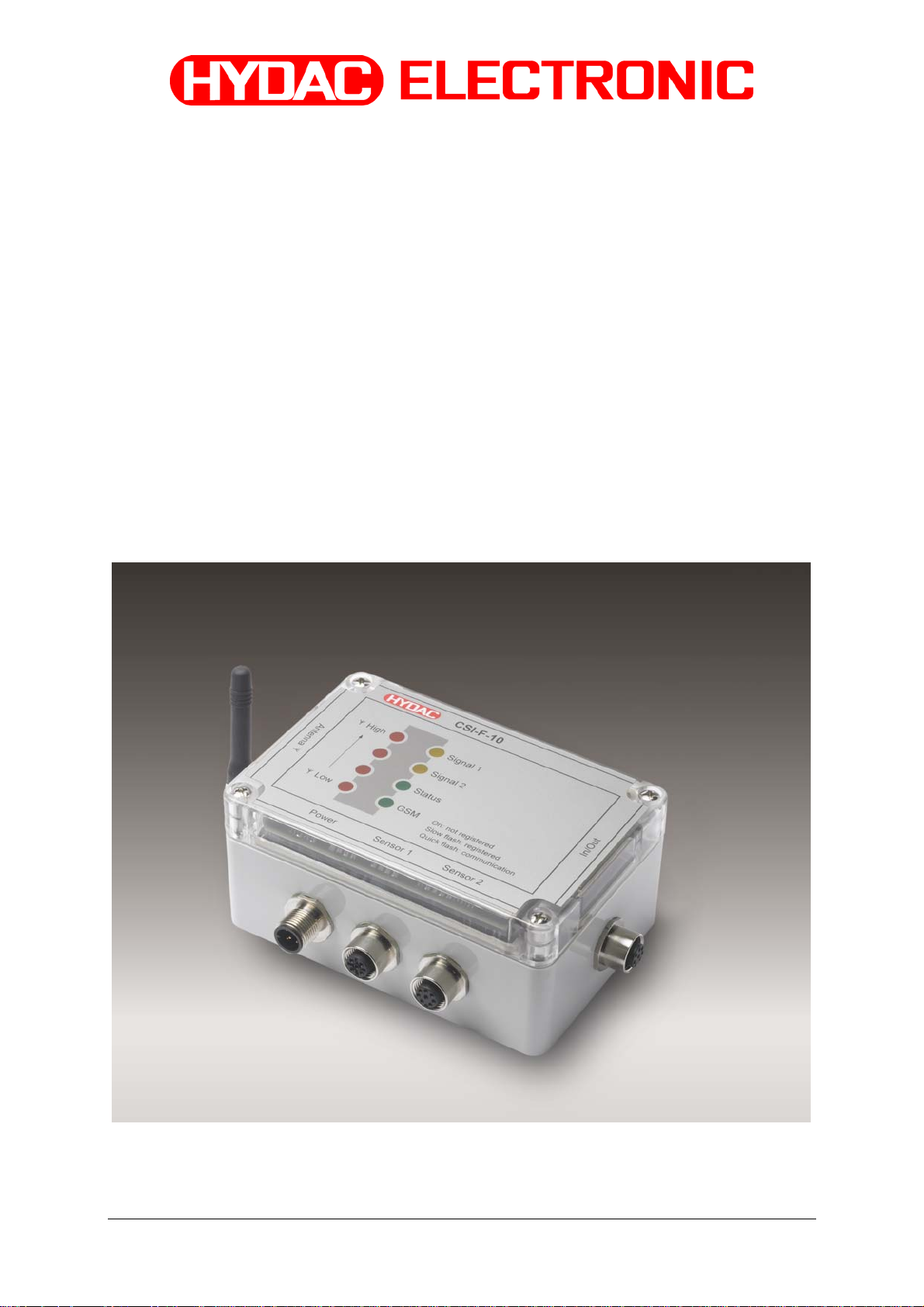
GSM Radio Module
CSI-F-10
User Manual
English (translation of original instructions)
Status 29.01.2009 HYDAC ELECTRONIC GMBH Part.-Nr.: 669752
Page 2

GSM Radio Module CSI-F-10 Page 2
Status 29.01.2009 HYDAC ELECTRONIC GMBH Part.-Nr.: 669752
Page 3

GSM Radio Module CSI-F-10 Page 3
Table of Contents
General...........................................................................................................................9
1
1.1 Previous Knowledge..............................................................................................9
1.2 Structure of the Manual.........................................................................................9
1.3 Copyright Protection ...........................................................................................10
1.4 Note on Warranty.................................................................................................10
1.5 Declaration of Conformity .........................................................................10
2 Safety ...........................................................................................................................11
2.1 General Safety Precautions ................................................................................11
2.2 Antenna.................................................................................................................12
2.3 Electronic Devices...............................................................................................12
2.4 Potentially Explosive Substances / Locations..................................................12
2.5 Air travel ...............................................................................................................12
2.6 Safety-Related Applications ...............................................................................12
2.7 SIM card................................................................................................................12
2.8 Loss / Theft of the SIM card or of the Device....................................................12
3 Proper/Designated Use...............................................................................................13
3.1 Stand alone operation.........................................................................................14
3.2 Operation as GSM modem on a CMU 1000........................................................14
4 Installation...................................................................................................................15
4.1 Unpacking.............................................................................................................15
4.2 Installing the Unit.................................................................................................15
5 Setup and Function.....................................................................................................16
5.1 Display elements / Connections.........................................................................16
5.2 Pin connections...................................................................................................17
5.3 Connection examples for sensors .....................................................................18
5.3.1 HYDACLab® to Connection 1 and CS 1000 to Connection 2 ......................... 18
5.3.2 AS 1000 to Connection 1 and CS 1000 to Connection 2................................19
5.3.3 HYDACLab® and AS 1000 to Connection 1.................................................... 20
5.4 Connection to Condition Monitoring Unit CMU 1000 .......................................21
6 Commissioning...........................................................................................................22
6.1 Insert SIM card.....................................................................................................22
6.2 Program enable....................................................................................................23
6.3 Voltage supply with communication via direct connection with interface
module CSI-B-2...............................................................................................................24
6.3.1 Device Connection..........................................................................................25
6.3.2 Connection Setup ........................................................................................... 26
Status 29.01.2009 HYDAC ELECTRONIC GMBH Part.-Nr.: 669752
Page 4

GSM Radio Module CSI-F-10 Page 4
6.4 Voltage supply with communication via direct connection to Portable Data
Recorder HMG 510..........................................................................................................34
6.4.1 Device Connection..........................................................................................35
6.4.2 Connection Setup ........................................................................................... 36
6.5 Voltage supply with communication via GSM mobile radio connection
(standard application)....................................................................................................44
6.5.1 Device connection ..........................................................................................45
6.5.2 Connection Setup ........................................................................................... 45
6.6 Voltage supply and communication via Condition Monitoring Unit CMU 1000..
...............................................................................................................................52
6.6.1 Device Connection..........................................................................................52
6.6.2 Connection Setup ........................................................................................... 53
7 Configuration Using CMWIN PC Software................................................................57
7.1 Actions..................................................................................................................57
7.1.1 Display Device Status ........................................................................................57
7.1.2 Display Device Information .............................................................................58
7.1.3 Display Measured Values ...............................................................................59
7.1.4 Performing a Dialog ........................................................................................60
7.1.5 Managing Configurations................................................................................63
7.1.6 Set bus address..............................................................................................64
7.1.7 Managing sensor constellations .....................................................................64
7.1.8 Sending a text message ................................................................................. 65
7.2 Extras....................................................................................................................66
7.2.1 Update Firmware ............................................................................................ 66
8 CM Editor.....................................................................................................................69
8.1 Menu Bar...............................................................................................................70
8.1.1 File .................................................................................................................. 70
8.1.2 CM Program ...................................................................................................71
8.1.3 Grouping ......................................................................................................... 75
8.1.4 Device.............................................................................................................75
8.1.5 Sensor constellation .......................................................................................76
8.1.6 Extras..............................................................................................................78
8.2 Window Divisions................................................................................................79
8.2.1 "Function Properties" Window ........................................................................79
8.2.2 "Function List" Window ...................................................................................79
8.2.3 "Linked Functions" Window ............................................................................ 79
8.2.4 "Functions" Window........................................................................................79
9 CM Program Functions...............................................................................................80
9.1 General Information Concerning Functions......................................................80
9.1.1 Inputs / Outputs ..............................................................................................80
9.1.2 Parameters ..................................................................................................... 81
9.2 Data Sources........................................................................................................82
9.2.1 Numerical Constant ........................................................................................ 82
9.2.2 Measured value .............................................................................................. 82
9.2.3 Digital Input.....................................................................................................82
9.2.4 Numerical Entry .............................................................................................. 83
9.2.5 Boolean Entry ................................................................................................. 83
9.2.6 Time Sensor ...................................................................................................84
9.2.7 Clock Timer.....................................................................................................84
Status 29.01.2009 HYDAC ELECTRONIC GMBH Part.-Nr.: 669752
Page 5

GSM Radio Module CSI-F-10 Page 5
9.2.8 Error Event......................................................................................................85
9.2.9 Boolean Constants .........................................................................................85
9.3 Numerical Calculations.......................................................................................86
9.3.1 Addition...........................................................................................................86
9.3.2 Subtraction......................................................................................................86
9.3.3 Multiplication ................................................................................................... 86
9.3.4 Division ........................................................................................................... 86
9.3.5 Division Remainder.........................................................................................87
9.3.6 Absolute Value................................................................................................87
9.3.7 Change of Algebraic Sign ............................................................................... 87
9.3.8 Rounding ........................................................................................................87
9.3.9 Raising to a Higher Power ..............................................................................88
9.3.10 Square Root....................................................................................................88
9.3.11 Power at Base e .............................................................................................88
9.3.12 Natural Logarithm ........................................................................................... 88
9.3.13 Decade Logarithm ..........................................................................................89
9.3.14 Integral............................................................................................................89
9.3.15 Differential Quotient ........................................................................................ 90
9.4 Numerical Operations..........................................................................................91
9.4.1 Minimum ......................................................................................................... 91
9.4.2 Maximum ........................................................................................................91
9.4.3 Limit ................................................................................................................ 91
9.4.4 If - then - else..................................................................................................91
9.4.5 Median Value..................................................................................................92
9.4.6 Note Value ...................................................................................................... 92
9.4.7 Note Minimum.................................................................................................92
9.4.8 Note Maximum................................................................................................93
9.4.9 Tabular Value .................................................................................................93
9.4.10 Tabular Index..................................................................................................94
9.4.11 Characteristic Curve ....................................................................................... 94
9.4.12 Ramp .............................................................................................................. 95
9.5 Counting Functions.............................................................................................96
9.5.1 Count Pulses ..................................................................................................96
9.5.2 Stop Watch ..................................................................................................... 96
9.6 Numerical Conditions..........................................................................................97
9.6.1 Equals.............................................................................................................97
9.6.2 Does not Equal ............................................................................................... 97
9.6.3 Greater than....................................................................................................98
9.6.4 Greater than or Equal to ................................................................................. 98
9.6.5 Less than ........................................................................................................ 98
9.6.6 Less than or Equal to......................................................................................99
9.6.7 Within..............................................................................................................99
9.6.8 Outside ...........................................................................................................99
9.7 Boolean Links ....................................................................................................100
9.7.1 Not ................................................................................................................ 100
9.7.2 And ...............................................................................................................100
9.7.3 Not - And.......................................................................................................100
9.7.4 Or..................................................................................................................101
9.7.5 Not - Or .........................................................................................................101
9.7.6 Exclusive Or..................................................................................................102
9.7.7 Not Exclusive Or ...........................................................................................102
Status 29.01.2009 HYDAC ELECTRONIC GMBH Part.-Nr.: 669752
Page 6

GSM Radio Module CSI-F-10 Page 6
9.8 Other Boolean Operations ................................................................................103
9.8.1 Note Switching Status...................................................................................103
9.8.2 Switching Delay ............................................................................................ 103
9.8.3 T - Flipflop.....................................................................................................104
9.8.4 Mono Flop.....................................................................................................104
9.8.5 RS - Flipflop .................................................................................................. 105
9.8.6 Pulse Generation .......................................................................................... 105
9.9 Result Values .....................................................................................................106
9.9.1 Numerical Output Value................................................................................106
9.9.2 Boolean Output Value...................................................................................107
9.10 Actions................................................................................................................108
9.10.1 Setting Switching Output ..............................................................................108
9.10.2 Switch on LED .............................................................................................. 108
9.10.3 Send SMS.....................................................................................................108
9.11 Other ...................................................................................................................109
9.11.1 Comment ...................................................................................................... 109
10 Error Messages CM Program Compilation..........................................................110
10.1 Overriding Error Messages...............................................................................111
10.1.1 Function not Available in this Mode .............................................................. 111
10.2 Error Messages with Data Sources..................................................................111
10.2.1 Invalid Channel Setting.................................................................................111
10.2.2 Duplicate Channel Name..............................................................................111
10.2.3 Invalid Digital Input .......................................................................................111
10.2.4 Duplicate Digital Input...................................................................................111
10.2.5 Too many Boolean Input Fields ....................................................................111
10.2.6 No Inscription for Boolean Input ...................................................................111
10.2.7 Duplicate Inscription for Boolean Inputs ....................................................... 111
10.2.8 Too Many Numerical Input Values................................................................111
10.2.9 No Inscription for Numerical Input ................................................................112
10.2.10 Duplicate Inscription for Numerical Input ..................................................112
10.2.11 Duplicate Error Source ..............................................................................112
10.3 Error Messages for Operations/Conditions.....................................................112
10.3.1 Upper and Lower Measured Value Limits too Close to one another ............112
10.3.2 Measured Value Limits Outside the Range of -30000 to 30000 ...................112
10.3.3 Lower Measured Value Limit Greater than Upper Measurement Value Limit112
10.4 Error Messages with Result Values/Actions...................................................112
10.4.1 Invalid Output LED Selected.........................................................................112
10.4.2 Duplicate Use of Output LED........................................................................112
10.4.3 Invalid Digital Output.....................................................................................113
10.4.4 Duplicate Digital Ouput ................................................................................. 113
10.4.5 Too Many Boolean Output Fields .................................................................113
10.4.6 Duplicate Boolean Output Field .................................................................... 113
10.4.7 The Bit Number Must Be a Figure between 0 and 14................................... 113
10.4.8 Too Many Numerical Output Fields ..............................................................113
10.4.9 Duplicate Numerical Output Field .................................................................113
10.4.10 Message and telephone number too long .................................................113
Status 29.01.2009 HYDAC ELECTRONIC GMBH Part.-Nr.: 669752
Page 7

GSM Radio Module CSI-F-10 Page 7
11 Specifications........................................................................................................114
11.1 Power Supply.....................................................................................................114
11.2 Sensor Inputs (5 pole female connection "Sensor 1", 8 pole female
connection "Sensor 2")................................................................................................114
11.3 Logic measurement channels ..........................................................................114
11.4 Digital Inputs and Outputs (8 pole female connection "In/Out")...................114
11.5 Interfaces............................................................................................................114
11.6 Cycle Time..........................................................................................................115
11.7 Operating and Ambient Conditions .................................................................115
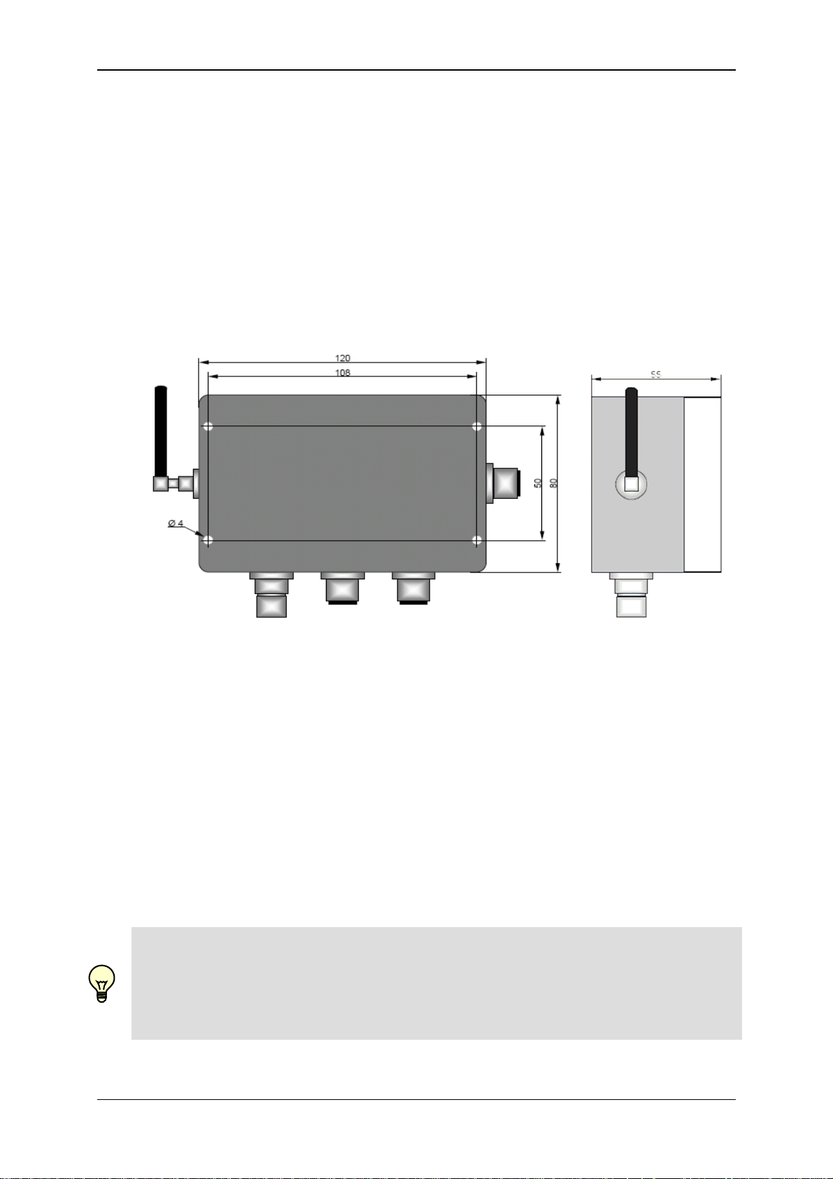
11.8 Dimensions and Weight:...................................................................................115
11.9 Technical Standards..........................................................................................115
11.10 Items supplied ................................................................................................115
11.11 Maintenance and cleaning.............................................................................115
11.12 Recycling and Disposal.................................................................................116
12 Ordering Details.....................................................................................................117
13 Exclusion of liability..............................................................................................117
14 Accessories ...........................................................................................................118
Status 29.01.2009 HYDAC ELECTRONIC GMBH Part.-Nr.: 669752
Page 8

GSM Radio Module CSI-F-10 Page 8
Preface
We have compiled the most important instructions for the operation and
maintenance of our product for you, its user, in this documentation.
It will acquaint you with the product and assist you in using it as intended in
an optimal manner.
Keep it in the vicinity of the product so it is always available.
Note that the information on the unit's engineering contained in the
documentation was that available at the time of publication. There may be
deviations in technical details, figures, and dimensions as a result.
If you discover errors while reading the documentation or have additional
suggestions or notes, contact us at:
HYDAC ELECTRONIC GMBH
Technical Documentation
Hauptstraße 27
66128 Saarbrücken
-GermanyTel: +49(0)6897 / 509-01
Fax: +49(0)6897 / 509-1726
Email: electronic@hydac.com
The editorial board would welcome your contributions.
„Putting experience into practice“
Status 29.01.2009 HYDAC ELECTRONIC GMBH Part.-Nr.: 669752
Page 9

GSM Radio Module CSI-F-10 Page 9
1 General
This manual is a constituent part of the device. It contains texts and graphics
concerning the correct handling of the product and must be read before installation,
assembly and the operation of the device.
The manual offers information concerning the safe operation, installation and
programming of the GSM radio module CSI-F-10. It is aimed at engineers,
programmers, fitters and maintenance personnel with a general knowledge of
automation technology.
By using this manual as recommended, you will ensure that the CSI-F-10 is put into
effective and safe operation as quickly as possible. The following questions are
covered in the next few points:
What prior knowledge must one have in order to be able to program the
CSI-F-10?
How is this manual structured?
What's the best way to use this manual?
What information can I find in this manual?
1.1 Previous Knowledge
No special previous knowledge is required for using and programming the CSI-F-10
GSM radio module.
A general knowledge of automation technology or memory-programmable controllers
and a knowledge of control technology or PLC programming will however be
advantageous and speed up the familiarization period.
1.2 Structure of the Manual
We have integrated a variety of different Help functions to make it easier to use this
manual. Please consult the Table of Contents to find a specific topic. A brief overview
is provided at the beginning of each Chapter listing the contents of that particular
Chapter.
Selective Reading
You will find notes in the side margins that make it easier to find particular sections.
Pictograms and markings are also given, and these are explained below.
Furthermore, this manual also contains instructions regarding personal safety and the
avoidance of property damage that must be observed. The instructions are highlighted
by a Warning symbol and displayed as follows, depending on the seriousness of the
hazard:
Status 29.01.2009 HYDAC ELECTRONIC GMBH Part.-Nr.: 669752
Page 10
GSM Radio Module CSI-F-10 Page 10
Danger
means that death, severe bodily injury or considerable property damage will occur if the
respective precautionary measures are not implemented.
Warning
means that death, severe bodily injury or considerable property damage could occur if
the respective precautionary measures are not implemented.
Caution
means that some non-severe bodily injury or property damage could occur if the
respective precautionary measures are not implemented.
Attention
means that an unwanted event or condition could occur if the respective instruction is
not followed.
Note
means an important piece of information about the product, its handling or a part of the
documentation to which particular attention should be paid.
In the event that several hazard levels occur simultaneously, it is always the highest
level warning notice that is used. If the warning triangle warns against possible
personal injury, then a warning against possible property damage can also be attached
to the same warning notice.
1.3 Copyright Protection
The dissemination and/or reproduction of this document, as well as the exploitation and
communication of its content, is not permitted unless specifically authorized.
Contraventions are liable to compensation. All rights reserved.
1.4 Note on Warranty
This manual was compiled with the greatest possible care. Nevertheless, errors or
deviations cannot be excluded, and for this reason we assume no responsibility for the
complete accuracy of the content.
In view of the fact that, despite intensive endeavors, errors can never be completely
avoided, we welcome tips and suggestions for improvement at any time.
1.5 Declaration of Conformity
This product is labelled with the CE Marking and thus is in compliance with current
German marketing authorization regulations and European standards.
As a consequence, compliance with the current regulations on electromagnetic
compatibility and the safety provisions of the Low-Voltage Directive is ensured.
This product complies with the provisions of the following European Directives:
EN 61000-6-1 / 2 / 3 / 4 and the R&TTE Directive 1999/5/EC.
Status 29.01.2009 HYDAC ELECTRONIC GMBH Part.-Nr.: 669752
Page 11

GSM Radio Module CSI-F-10 Page 11
2 Safety
2.1 General Safety Precautions
Follow the specifications contained in this description. Non-observance of the
instructions, operation in applications other than those outlined below, incorrect
installation/assembly or incorrect handling of the product can be severely detrimental to
the safety of personnel and systems/machines and will invalidate warranty and liability
claims.
Immediately after unpacking, check that all items have been supplied correctly and that
the device is in perfect condition.
The device may not be commissioned or operated except by qualified personnel who
can be regarded as being "competent" as defined in the EMC and Low Voltage
Directives.
Qualified personnel are individuals who are authorized to operate, ground and label
devices, systems and electrical circuits in accordance with safety standards.
All relevant and generally recognized safety requirements must be complied with.
If the voltage supply to the device is not provided by an on-board electrical system
(24 V battery operation), then care must be taken to ensure that the external voltage is
generated and routed in accordance with the criteria for safe low voltage (SELV
[Separated Extra Low Voltage] pursuant to EN 60950), in view of the fact that this is
available for supplying the connected control system, sensor system and actuating
elements without any other additional measures being implemented.
The wiring of all of the signals connected with the SELV circuit in the device must also
meet the SELV criteria (safe extra low voltage with protective separation from other
electrical circuits).
If the SELV voltage supplied is grounded externally (PELV according to EN 50178),
then responsibility for this and for compliance with any applicable national installation
regulations rests with the operator.
All of the statements made in this manual refer to devices which are not grounded in
terms of the SELV voltage.
Generally speaking, DIN VDE 0100 Part 410 must be observed for the supply voltage.
Only the particular signals which are specified in the Technical Data and/or on the
device label may be supplied to the connections and only authorized HYDAC
ELECTRONIC GMBH accessory components may be connected to them.
In accordance with the following technical specifications, the device can be operated in
a wide range of ambient temperatures. Due to the additional self-heating of the device,
high contact temperatures may develop on the housing in hot environments.
In the event of faults or if anything is unclear, please contact your nearest HYDAC
representative. Tampering with the unit can have severe consequences for personal
and system safety. These are not permitted and will invalidate all liability and warranty
claims.
Fault investigation and repairs may only be carried out by HYDAC SERVICE GMBH
Customer Service Department.
Status 29.01.2009 HYDAC ELECTRONIC GMBH Part.-Nr.: 669752
Page 12

GSM Radio Module CSI-F-10 Page 12
2.2 Antenna
Operating the radio module without attaching the antenna or when the antenna is
faulty, can damage the unit.
2.3 Electronic Devices
Operating the CSI-F-10 can under certain circumstances adversely affect the
functioning of other electronic devices if they are not screened correctly.
Please contact the manufacturer of the particular device in the event of failure.
Do not operate the GSM radio module CSI-F-10 in the vicinity of medical equipment!
2.4 Potentially Explosive Substances / Locations
The radio modules in the series CSI-F-10 may not be operated in the vicinity of fuel
stations, fuel depots, chemical plants or blasting work.
When operated in off-highway vehicles, construction, agricultural or other machinery,
no flammable gases, fluids or other explosive substances may be transported or stored
in the parts of the vehicles in which the radio module is mounted.
2.5 Air travel
The GSM radio module CSI-F-10 must not be operated on board aeroplanes,
helicopters or other aircraft.
Operation in one of the above-mentioned aircraft, would adversely affect the
navigation, control and / or communication systems.
Contraventions can result in legal proceedings against offenders.
2.6 Safety-Related Applications
Do not install the GSM radio module CSI-F-10 for safety-related applications (to DIN
EN ISO 13849-1 Functional Safety).
2.7 SIM card
Please note that a SIM card is required to operate each CSI-F-10. You can obtain SIM
cards from the usual providers, such as T-Mobile, VODAFONE or E-Plus.
Deactivate the mailbox function and the caller ID restriction.
2.8 Loss / Theft of the SIM card or of the Device
In order to prevent fraudulent use, inform your network operator immediately if the SIM
card or the radio module is lost or stolen.
Status 29.01.2009 HYDAC ELECTRONIC GMBH Part.-Nr.: 669752
Page 13
GSM Radio Module CSI-F-10 Page 13
3 Proper/Designated Use
The GSM radio module CSI-F-10 is an electronic unit with universal application for
transferring data and digital signals via the GSM mobile radio network. The device can
be used in both stand-alone operation and as a GSM modem on a CMU 1000 (HYDAC
Condition Monitoring Unit).
A maximum of two HYDAC SMART sensors with HSI interface (automatic sensor
recognition), e.g. HYDACLab
connections.
In addition, several other system statuses can be monitored via the four integral digital
inputs and transmitted in binary using the two integral digital outputs. The device can
also access the machine / system being monitored directly via these digital outputs.
The sensor values, statuses etc can be requested by SMS/text. To do this an SMS with
the text "Values" must be sent to the CSI-F-10. The device then automatically sends
one or several reply text messages containing all the sensor values and additional
information available.
Note!
The GSM radio module CSI-F-10 only replies or accepts data connections if the
telephone number of the sender is visible and has been registered in the authorized
telephone numbers in the CSI-F-10 (see Chap. 7.1.4).
The CSI-F-10 devices are designed for use in difficult conditions. They are therefore
suitable for direct installation in machines and systems and in stationary and mobile
off-highway applications (not for public road and rail transport!).
The inputs and outputs are designed to a special specification for such applications.
Integrated hardware and software functions (operating system) provide a greater level
of protection for the machine.
Examples of possible applications:
Remote parameterization of HYDAC Condition Monitoring units and sensors in
stationary or mobile machines and systems
Remote diagnostics of system conditions
Transmission of alarm messages as SMS
Read-outs of operating conditions from machines that are running
...
Warning!
The device may be used only for the types of applications specified in the manual and
only in connection with accessory components authorized by HYDAC ELECTRONIC
GMBH. The trouble-free and safe operation of the product is contingent on proper
transport; storage, setup and installation; and on careful operation and maintenance.
®
, AS 1000 or CS 1000, can be connected to its input
Status 29.01.2009 HYDAC ELECTRONIC GMBH Part.-Nr.: 669752
Page 14

GSM Radio Module CSI-F-10 Page 14
The two basic operating modes available for using the GSM radio module CSI-F-10 are
described below:
3.1 Stand alone operation
The CSI-F-10 transmits the measured values and additional information of the
connected sensors directly and without processing them (passive mode) or monitors
and processes the input signals with a "CM program" stored in the unit (active mode).
The application software for the active mode, das "CM Program", can be readily
generated by the user using the "CM Editor" on a PC. The "CM Editor" is a component
part of the HYDAC PC software "CMWIN", version 3.0 or higher.
In the above-mentioned "CM program" you define in detail which data will be monitored
and how, and when and which type of message should occur.
For example, once a parameterized limit has been exceeded, an alarm SMS can be
sent or a switch output can be set. All texts and telephone numbers for the relevant
SMS must be stored in the CM program by the user.
Note!
All of the programming procedures and software functions subsequently described in
this documentation refer to the "CM Editor" in accordance with IEC 61131.
The operator is responsible for the safe and application-appropriate functioning of the
CM Programs that he or she generates.
3.2 Operation as GSM modem on a CMU 1000
When using the unit as a GSM modem, the CSI-F-10 must be connected via HSI signal
(HYDAC sensor interface) to the CMU 1000. The CMU 1000 is in this case the "bus
master" and controls the radio module.
In this operating mode, one or more sensors are monitored by the CMU 1000. Their
input signals are evaluated according to the CM program stored in the CMU 1000 and
processed.
The resulting data and / or messages are transmitted from the CMU 1000 via HSI
interface to the GSM radio module. The radio module transfers this data and / or
messages controlled by the CMU 1000 directly by SMS.
The SMS text and the receiving telephone number are stored in the CM program in the
CMU 1000 for this purpose.
Status 29.01.2009 HYDAC ELECTRONIC GMBH Part.-Nr.: 669752
Page 15
GSM Radio Module CSI-F-10 Page 15
4 Installation
4.1 Unpacking
The CSI-F-10 is supplied in a cardboard box. When taking delivery and when
unpacking the unit, check it for transit damage and report any damage to the carrier
immediately.
4.2 Installing the Unit
Only fit the unit in locations where the radio module can be operated without risk (see
Chapter 2. Safety).
When you are planning the layout for your system, allow sufficient space
underneath the unit and to the right of the unit, and distance between it and other
devices for cabling the peripherals and for connecting the communication cable.
Mount the GSM radio module using the mounting holes provided in the lower part
of the housing. To do this, the housing cover of the radio module must be
removed.
When installing in off-highway vehicles, construction & agricultural machinery etc,
avoid placing near to fuel tanks, tanks containing explosive substances or
electronic components which are inadequately screened.
Do not fit the antenna in enclosed metal constructions, such as a driver's console
or cab, or similar (Faraday screening effect).
Do not lengthen or shorten any antenna lines.
Note!
The condition for a stable GSM mobile radio connection is a good antenna signal.
If problems occur, change the position of the antenna or the mobile device. Also, if the
antenna plug is not tightly fitted this will cause a loss of signal!
The antenna connection must be protected from humidity and moisture.
Status 29.01.2009 HYDAC ELECTRONIC GMBH Part.-Nr.: 669752
Page 16
GSM Radio Module CSI-F-10 Page 16
5 Setup and Function
The GSM radio module CSI-F-10 is an electronic device with universal applications for
transmitting data and digital signals over the GSM mobile radio network.
A maximum of two HYDAC SMART sensors with HSI interface (automatic sensor
recognition), e.g. HYDACLab
connections.
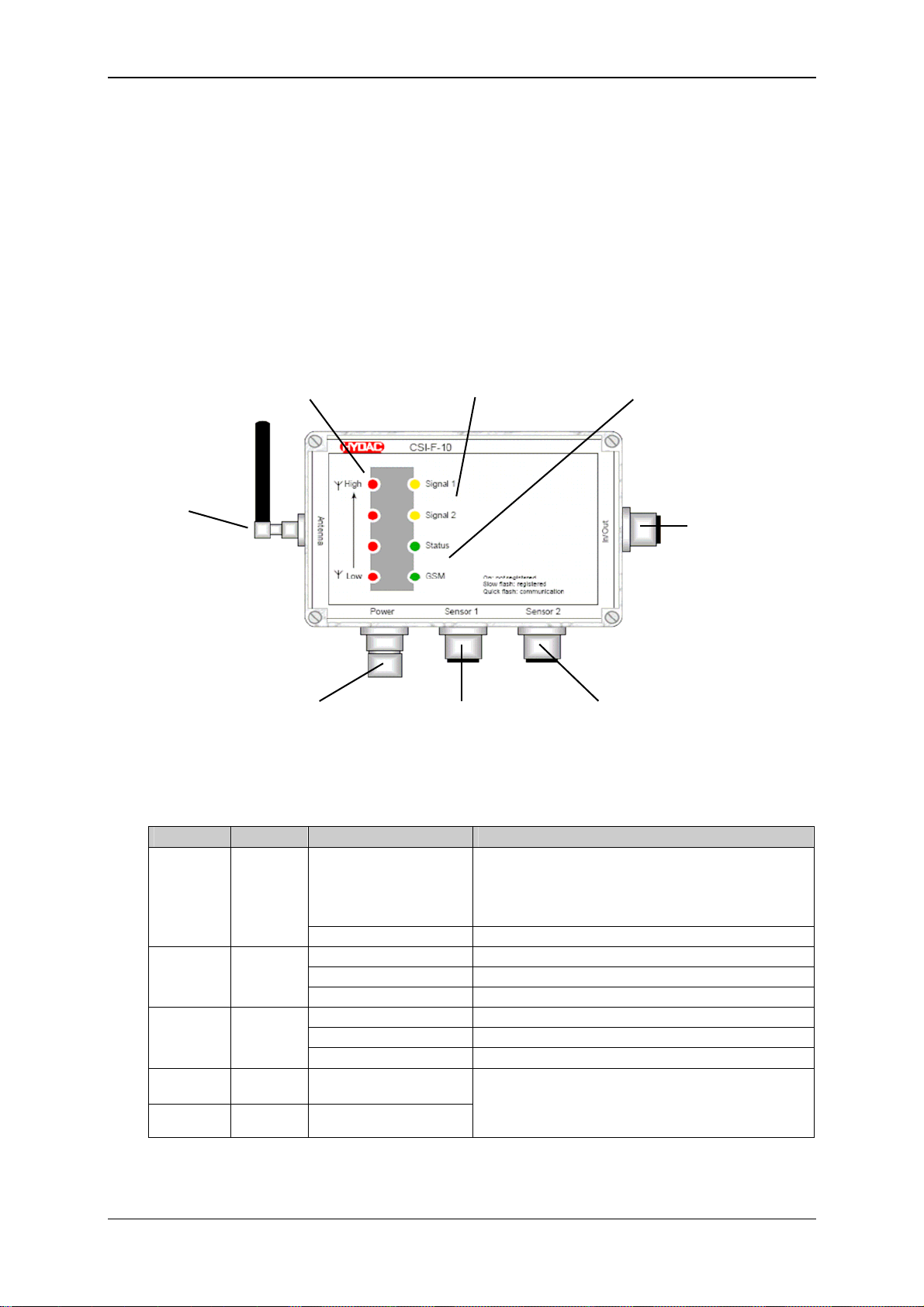
5.1 Display elements / Connections
4x LED red: 2x LED yellow: 2x LED green:
reception strength user configuration status sensor recognition
GSM network via CM program GSM activity
GSM antenna
In / Out socket:
Dig. Input 1, 2, 3, 4
Dig. Output 1, 2
with supply
Power connection: Sensor 1: Sensor 2:
voltage supply. AS 1000 / CS 1000
HSI-Master HYDACLab
HSI + supply HSI + supply
LED Color Condition Meaning
High
red
Low
GSM green
Status green
Signal 1 yellow On / Off
Signal 2 yellow On / Off
On
All Off No reception
On Not registered
Rapid flashing Communication
Slow flashing Registered
On Min. 1 sensor recognised
Flashing PC connection active
Off No sensor recognised
®
, AS 1000 or CS 1000, can be connected to its input
®
4 LEDs: reception strength > 75 %
3 LEDs: reception strength > 50 %
2 LEDs: reception strength > 25 %
1 LED: reception strength < 25 %
Function according to CM program
(programmable user application)
In the initialization phase (approx. 10 sec.) the LEDs will not indicate any defined
condition.
Status 29.01.2009 HYDAC ELECTRONIC GMBH Part.-Nr.: 669752
Page 17
GSM Radio Module CSI-F-10 Page 17
5.2 Pin connections
Plug Pin Function I/O
1 +UB (in)
2 n.c.
Power
Plug Pin Function I/O
Sensor 1
(AS 1000
HLB 1000)
Plug Pin Function I/O
Sensor 2
(CS 1000)
Plug Pin Function I/O
In / Out
3 0 V
4 n.c.
5 HSI
1 +UB (out)
2 n.c.
3 n.c.
4 0 V
5 HSI IN / OUT
1 +UB (out)
2 n.c.
3 0 V
4 n.c.
5 HSI IN / OUT
6 n.c.
7 n.c.
8 n.c.
1 Digital Out 1 OUT
2 Digital In 1 IN
3 +UB (out)
4 Digital In 2 IN
5 0 V
6 Digital In 3 IN
7 Digital In 4 IN
8 Digital Out 2 OUT
Status 29.01.2009 HYDAC ELECTRONIC GMBH Part.-Nr.: 669752
Page 18
GSM Radio Module CSI-F-10 Page 18
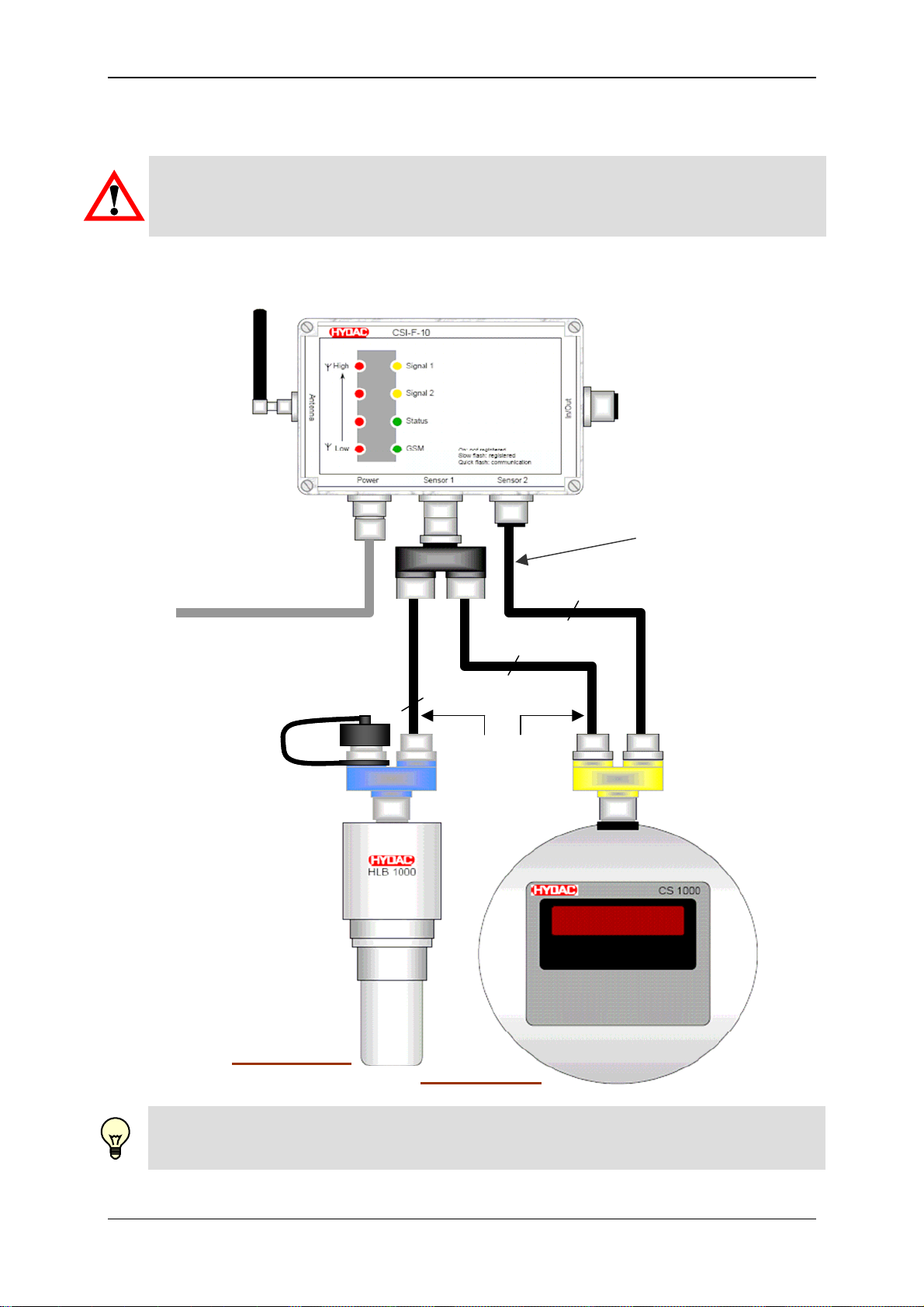
5.3 Connection examples for sensors
Warning!
The total length of the connected sensor cables (Sensor 1 + Sensor 2) may not exceed
max. 40 m. If this 40 m length is exceeded, there can be problems with the HSI signal
transmission.
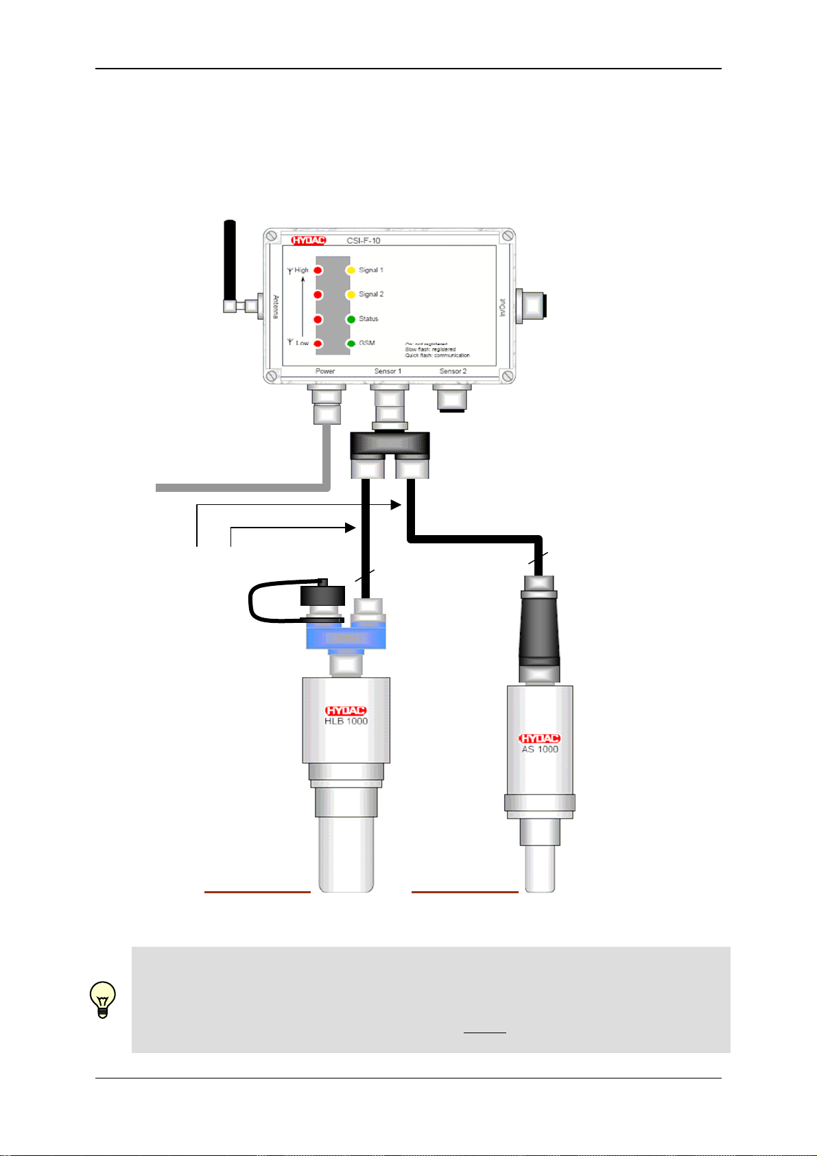
5.3.1 HYDACLab® to Connection 1 and CS 1000 to Connection 2
In this case, only voltage
supply for CS 1000!
Voltage supply / HSI
see Chap. 6.3 to 6.6
A ZBE 26 B
ZBE 38
8 pole, max. 30m
5 pole, max. 30m
5 pole, max. 30m
In total
max. 40m
A ZBE 41 B
HSI Address "a"
HSI Address "b"
Note!
Connection "A" of the ZBE 26 (blue Y adaptor) must be sealed using the protective cap
provided, to protect it from dirt and moisture!
Status 29.01.2009 HYDAC ELECTRONIC GMBH Part.-Nr.: 669752
Page 19
GSM Radio Module CSI-F-10 Page 19
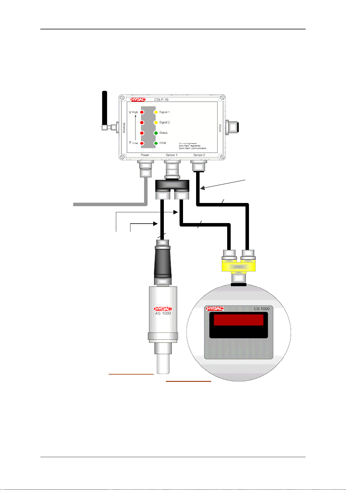
5.3.2 AS 1000 to Connection 1 and CS 1000 to Connection 2
In this case, only voltage
supply for CS 1000!
ZBE 38
Voltage supply / HSI
see Chap. 6.3 to 6.6
8 pole, max. 30m
5 pole, max. 30m
In total
max. 40m
5 pole, max. 30m
ZBE 36
A ZBE 41 B
HSI Address "a"
HSI Address "b"
Status 29.01.2009 HYDAC ELECTRONIC GMBH Part.-Nr.: 669752
Page 20
GSM Radio Module CSI-F-10 Page 20
5.3.3 HYDACLab® and AS 1000 to Connection 1
ZBE 38
Voltage supply / HSI
see Chap. 6.3 to 6.6
in total
max. 40m
5 pole, max. 30m
A ZBE 26 B
HSI Address "b" HSI Address "a"
5 pole, max. 30m
A ZBE 26 B
A ZBE 41 B
ZBE 36
Note!
Regardless of the type of constellation, a maximum of 2 SMART sensors can be
connected to the CSI-F-10 and evaluated by the device. The connected sensors must
already be addressed using the HSI addresses "a" and "b".
In other words, each sensor must be addressed before
connecting to the CSI-F-10, for
example using an HMG 3000.
5.4
Status 29.01.2009 HYDAC ELECTRONIC GMBH Part.-Nr.: 669752
Page 21
GSM Radio Module CSI-F-10 Page 21
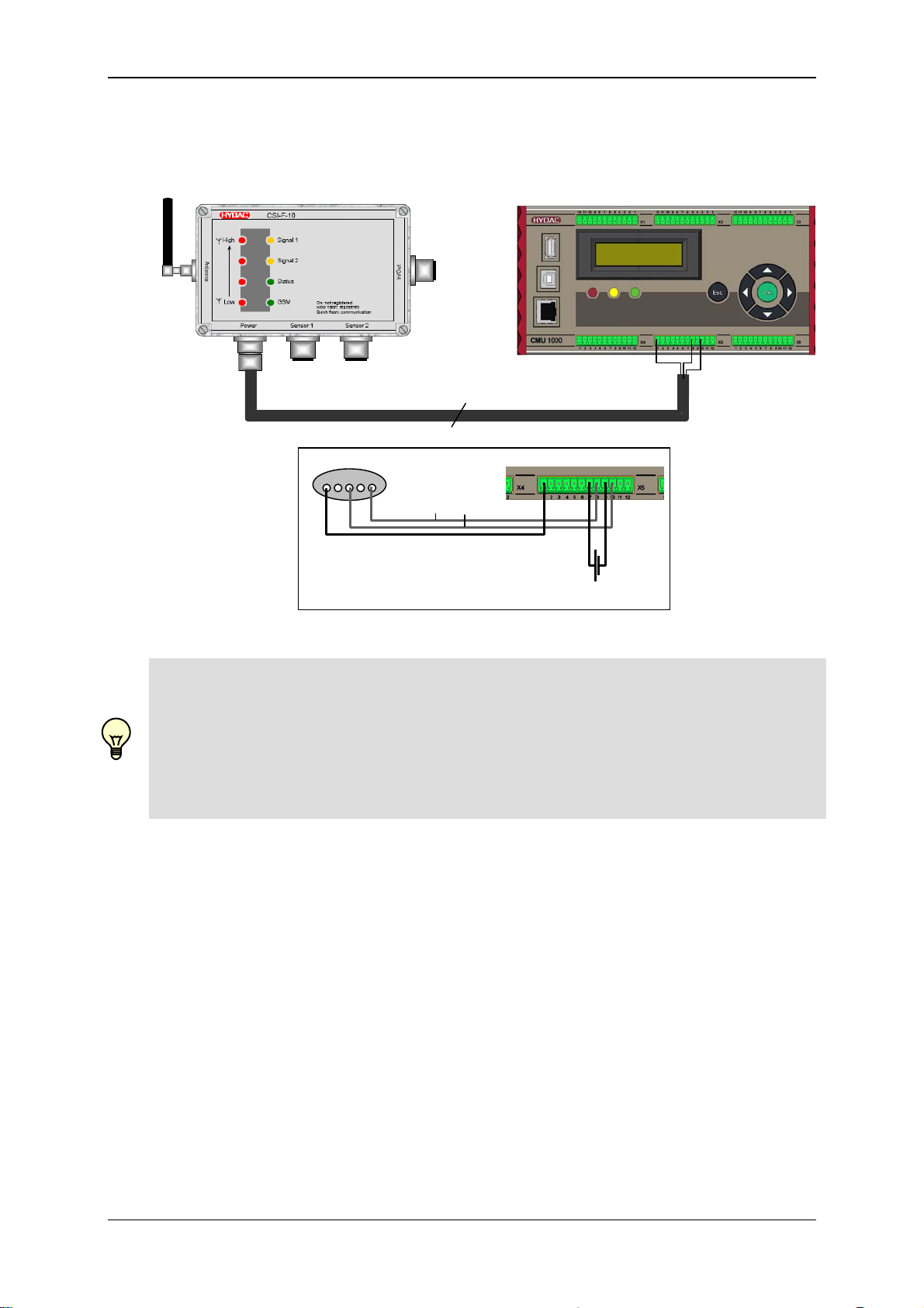
Connection to Condition Monitoring Unit CMU 1000
max. 30m
5 4 3 2 1
+U
0V
B
HSI
18..35 V DC / 3.5 A
Note!
For this connection option, the CMU 1000 can either be configured via the CSI-F-10, or
the CSI-F-10 can be configured via the CMU 1000.
In addition the CSI-F-10 acts as the GSM modem to the CMU 1000, to forward data
and / or messages sent from this unit (see Chap. 3.2.).
Similar to the SMART sensors, the CMU 1000 must also be addressed with an HSI
address ("a" or "b") before connecting to the CSI-F-10.
Status 29.01.2009 HYDAC ELECTRONIC GMBH Part.-Nr.: 669752
Page 22
GSM Radio Module CSI-F-10 Page 22
6 Commissioning
Note!
In order to be able to communicate later with the CSI-F-10 via GSM mobile radio, this
must first be configured. This means that the mobile phone numbers which are
authorized for access must be stored in the CSI-F-10 and appropriate permissions
assigned. In order to configure the GSM radio module CSI-F-10, first connect directly
with the GSM radio module CSI-F-10 (via CSI-B-2, HMG 510 or CMU 1000).
►See Chapter 6.3, 6.4 and 6.5!
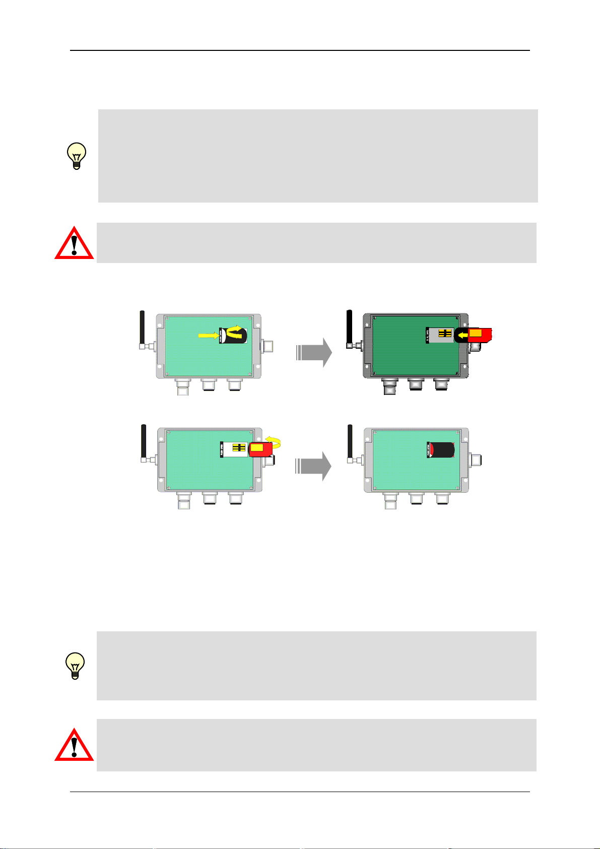
6.1 Insert SIM card
Warning!
Only ever insert or remove the SIM card when voltage supply is disconnected.
• Remove the housing cover by unscrewing the 4 mounting screws.
• Press on the catch "PUSH OPEN" and lift the SIM card holder to the right.
• Push the SIM card into the holder as per the diagram.
• Lift the holder again to the left, until it snaps back into the catch
• Replace the housing cover back onto the lower part of the housing.
The GSM radio module CSI-F-10 can only operate as such with a valid SIM card. This
card and the pin number for it can be obtained from your network operator or GSM
service provider.
For the direct transfer of data (online mode) you will need a SIM card which supports
the GSM data service and which is enabled for this. Some prepaid cards do not
support online direct transmission!
Use of pre-paid SIM cards!
Pre-paid SIM cards have a limited validity and limited credit. If the credit is used up or
the validity has expired, the function of the GSM radio module will no longer be
guaranteed!
Top up your pre-paid SIM card in good time!
Warning!
SIM cards and their contacts can easily be damaged by scratching or bending. When
handling the card, avoid placing any force on or touching the contacts.
Status 29.01.2009 HYDAC ELECTRONIC GMBH Part.-Nr.: 669752
Page 23
GSM Radio Module CSI-F-10 Page 23
PIN deactivation
If the PIN number is not input correctly or in full, during commissioning the SIM card
can be blocked.
We recommend therefore that the PIN of the SIM card is deactivated. To deactivate the
PIN code, place the SIM card in a mobile telephone and follow the device menu to
deactivate the PIN request.
Deactivating call forwarding / mailbox
Deactivate all the call forwards and the mailbox functions of the SIM card to be used to
achieve efficient accessibility with the CSI-F-10 GSM radio module.
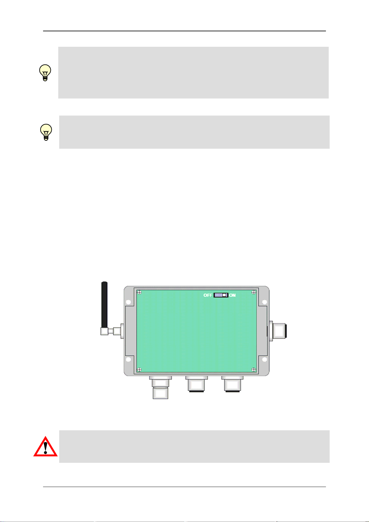
6.2 Program enable
Program enable is effected via a micro-switch on the upper right edge of the board.
Providing the switch is set to ON you can configure the CSI-F-10, make settings,
transfer CM programs etc via a PC connection, irrespective of the permissions
specified in the settings (see Chapter 7.1.4).
• Remove the housing cover.
• Push the switch to the right to "ON" to switch on the program enable.
• Push the switch to the left to "OFF" to switch off the program enable.
Warning!
When the programming enable is switched off (switch set to 'OFF') no settings,
program changes or other changes to the device configuration can be made via a PC
connection.
Status 29.01.2009 HYDAC ELECTRONIC GMBH Part.-Nr.: 669752
Page 24
GSM Radio Module CSI-F-10 Page 24
6.3 Voltage supply with communication via direct
connection with interface module CSI-B-2
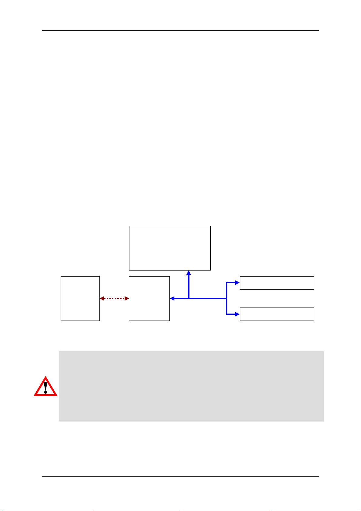
If a GSM radio module is connected to the PC via an adaptor such as the HYDAC
interface module CSI-B-2, then the GSM radio module has the HSI address "Bus
master".
If further sensors are connected to the CSI-F-10, these must be addressed with the
normal HSI address "a" or "b".
In order to be able to communicate with the GSM radio module or with the sensors
connected to it, the CSI-F-10 must first be addressed using the HSI address "bus
master". This means the GSM modem is switched into Slave mode and the PC works
as the bus master.
If afterwards a sensor connected to the CSI-F-10 is to be addressed, the connection
between PC and GSM radio module must be disconnected. In CMWIN a query
appears asking whether the master which was previously connected to the slave (the
CSI-F-10) should again be the master. This query must be answered with "No".
After this, the connection to the sensors which are connected to the CSI-F-10 can be
set up using the usual HSI addresses "a" or "b".
GSM radio module
CSI-F-10
(address 'bus master')
PC
RS232
RS485
CSI-B-2
Sensor (Address a)
HSI
Sensor (Address b)
Warning!
If the GSM radio module is directly connected to the PC and CMWIN via the HYDAC
interface module CSI-B-2 via HSI, no measured values are output and no new sensors
will be recognized.
In other words, if a sensor had been connected to the GSM radio module before the
connection setup, only those measured values which have been output directly prior to
the connection setup appear in CMWIN.
Furthermore, new sensors must be connected to the CSI-F-10 before the connection
setup because otherwise they will not be recognized.
Status 29.01.2009 HYDAC ELECTRONIC GMBH Part.-Nr.: 669752
Page 25
GSM Radio Module CSI-F-10 Page 25
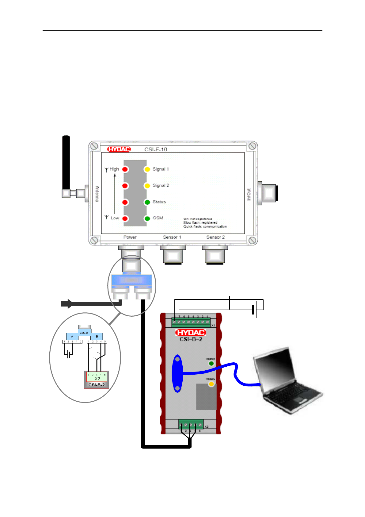
6.3.1 Device Connection
• Connect the RS232 serial interface of your PC with the 9-pin SUB-D socket of
the HYDAC interface module CSI-B-2 via a corresponding data cable (or
RS485 via terminal block).
• Connect the CSI-F-10 to the CSI-B-2 via the HSI connection
-X2 / Pin 3 and 4 on the CSI-B-2
Connection B / Pin 4 and 5 on ZBE 26 on the CSI-F-10
• Connect the voltage supply to the CSI-F-10 GSM radio module according to the
diagram.
Supply
voltage
10,5..35 V DC
+U
HSI
B
GND
A ZBE 26 B
18..35 V DC
0V
+U
RS232
(USB via
appropriate
adaptor)
Status 29.01.2009 HYDAC ELECTRONIC GMBH Part.-Nr.: 669752
Page 26
GSM Radio Module CSI-F-10 Page 26
6.3.2 Connection Setup
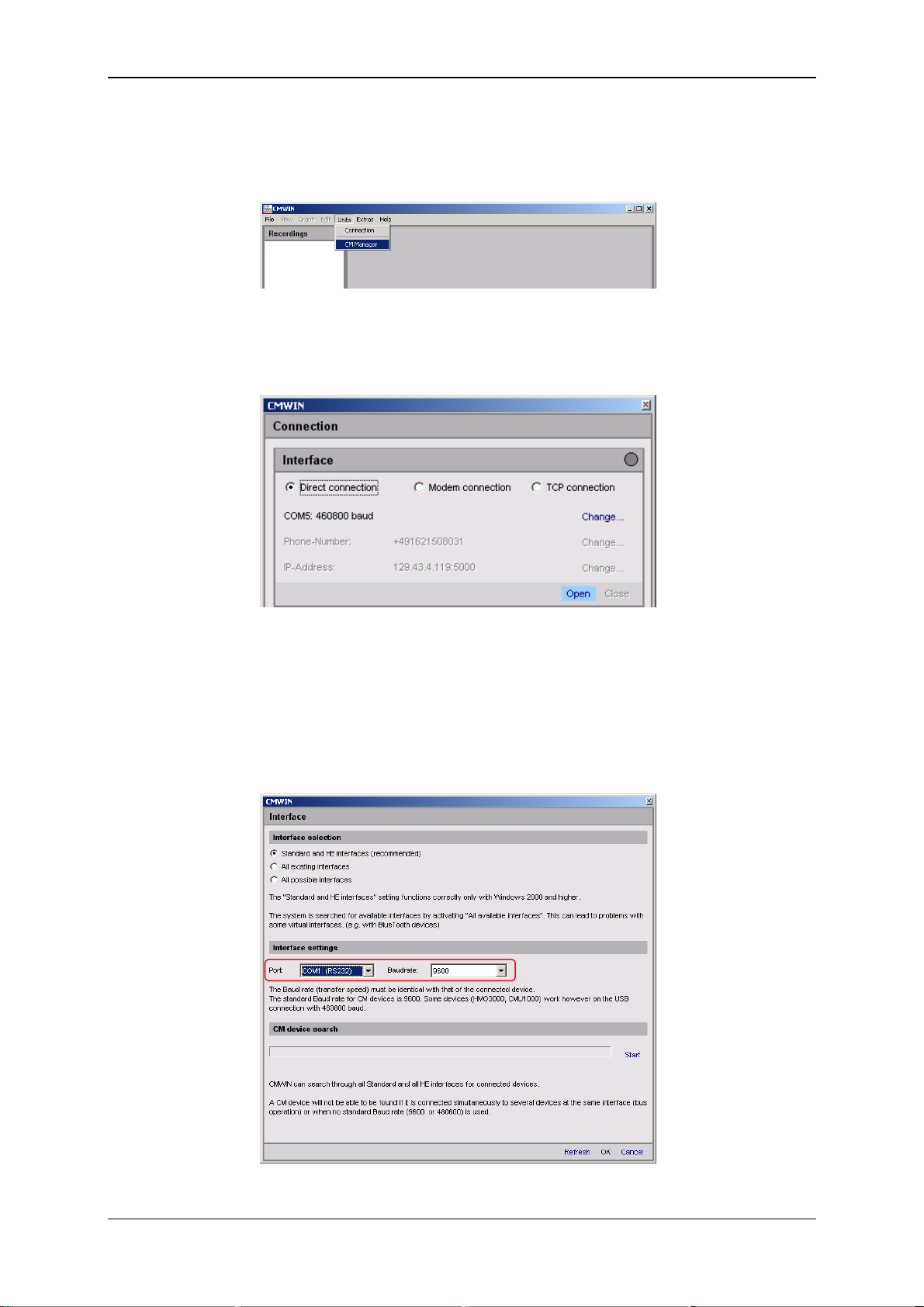
• Start the HYDAC PC software CMWIN
• In the Units Menu, select the "CM Manager" option.
• If the Connection window does not open automatically, select
"Connection" in the menu bar of the CM Manager.
• Select the option "Direct connection" in the window that opens.
• Click on "Change" in the top line to open the window for the interface settings.
• Make the corresponding preselection for the port settings in the window that
opens under Interface selection.
• Select the relevant port address and Baud rate under Interface settings. (9600
für CSI-B-2) aus.
• Click "Refresh" to update the interfaces marked under Interface selection in
terms of availability.
• Click on “OK“ to apply the modified settings or “Cancel“ to discard these
changes. In either case you will then return to the Connection window.
Status 29.01.2009 HYDAC ELECTRONIC GMBH Part.-Nr.: 669752
Page 27
GSM Radio Module CSI-F-10 Page 27
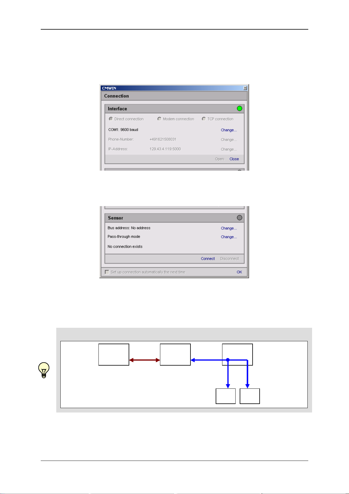
• In the Interface field, select the option "Open" in order to open the selected
interface (COM port).
The opened interface will be indicated by a green dot on the right-hand edge of
the window.
• In the Sensor field, specify whether you would like to connect to CSI-F-10
GSM radio module direct or to one of the sensors connected to it.
Afterwards, proceed according to the three options described below.
Schematic diagram of the connections!
PC
“CMWIN“
RS232
RS485
CSI-B-2
HSI
CSI-F-10
Sensor
“a“
Sensor
“b“
Status 29.01.2009 HYDAC ELECTRONIC GMBH Part.-Nr.: 669752
Page 28
GSM Radio Module CSI-F-10 Page 28
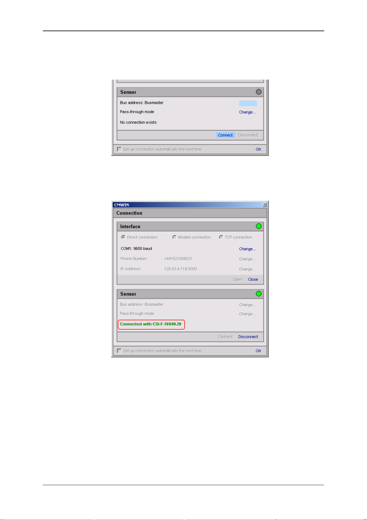
6.3.2.1 Connecting to the CSI-F-10
• Via "Change" in the Bus address line, open the selection window for the bus
address and select "Bus master".
Change...
• Afterwards click on "Connect" in the Sensor field to connect the CSI-F-10 to
the PC.
• The successful connection will be symbolized by a green dot on the right-hand
edge of the window.
• Pressing "Disconnect" in the Sensor field allows you to break the existing
connection between the CSI-F-10 and PC again.
• The interface (COM port) used can be closed again on the PC
by pressing "Close" in the Interface field.
• Click on "OK" to complete the connection setup and to
return to the CM Manager.
Status 29.01.2009 HYDAC ELECTRONIC GMBH Part.-Nr.: 669752
Page 29
GSM Radio Module CSI-F-10 Page 29
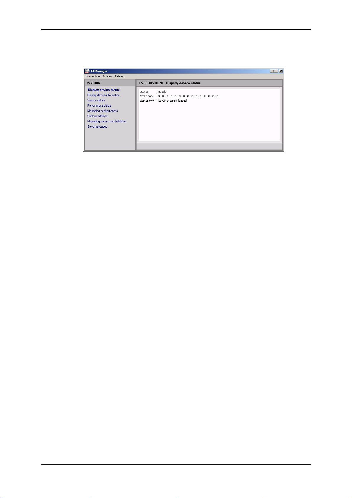
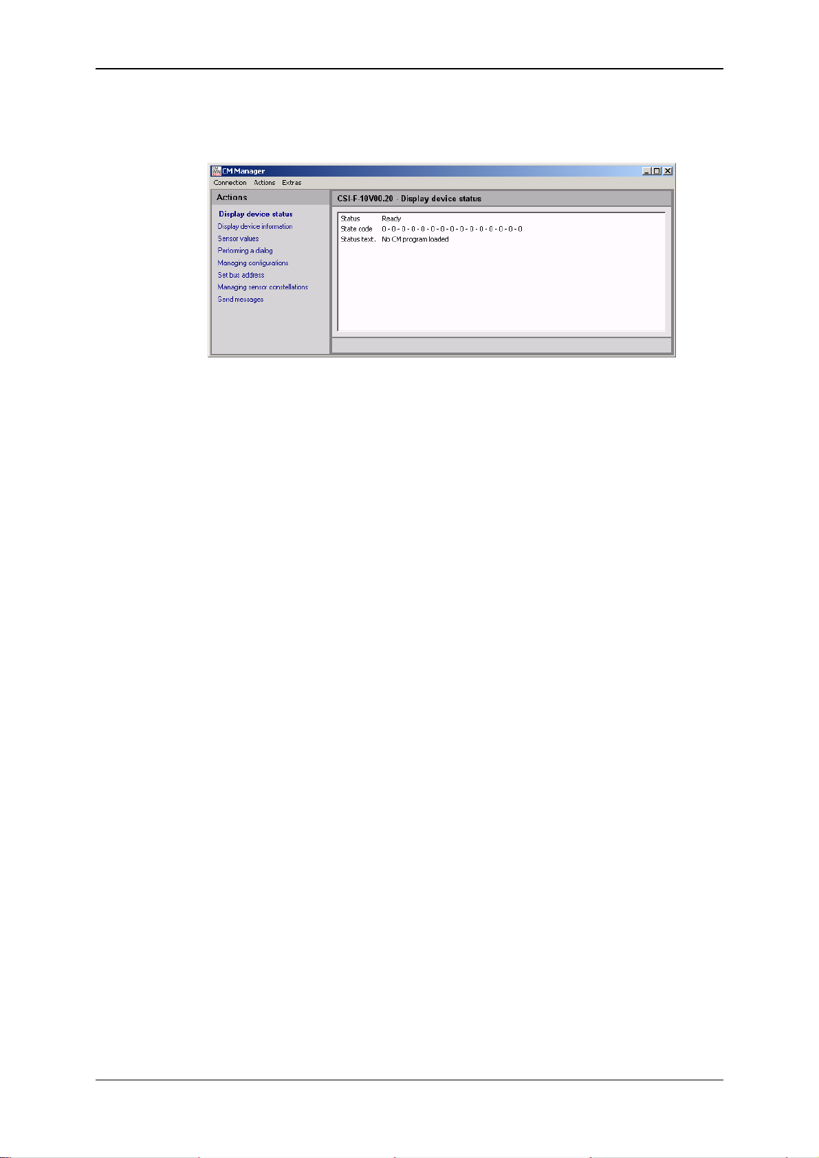
• The following window opens after the connection has been successfully
established:
The menu structure and window properties of the CM Manager are explained below in
greater detail in Chapter 7.
Status 29.01.2009 HYDAC ELECTRONIC GMBH Part.-Nr.: 669752
Page 30
GSM Radio Module CSI-F-10 Page 30
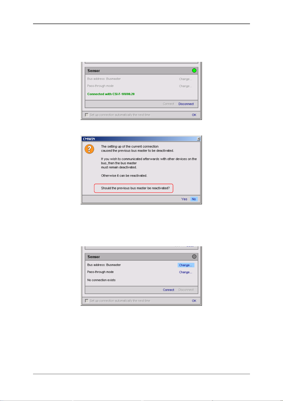
6.3.2.2 Connecting to the sensor by connection 1 (HSI address "a")
• Click on "Disconnect" under Connection in the Device box to break the existing
PC connection with the CSI-F-10.
• The following window opens:
• Then click on "No", so that the bus master is not reactivated.
1
• (!)
• Select Change in the Bus address line.
1
(!)
If you cancel at this stage and discontinue the connection to one of the connected sensors, after 5
minutes without communication a time-out occurs on the HSI bus.
This time-out causes the CSI-F-10 to be switched back independently to the bus master. This is
necessary so that the device can perform its monitoring function without being connected to CMWIN
both in the passive and active modes.
Status 29.01.2009 HYDAC ELECTRONIC GMBH Part.-Nr.: 669752
Page 31

GSM Radio Module CSI-F-10 Page 31
• The following window opens:
• Select the appropriate device address in the selection window
(Address a in our example).
• Confirm this with OK.
• Click on Connect to establish a link with the sensor.
• Successful establishment of the connection will be signaled as shown below:
• Click on Ok to establish the connection setup or on Disconnect to cancel the
connection setup.
Status 29.01.2009 HYDAC ELECTRONIC GMBH Part.-Nr.: 669752
Page 32

GSM Radio Module CSI-F-10 Page 32
6.3.2.3 Connecting to the sensor by connection 2 (HSI address "b")
• Click on "Disconnect" under Connection in the Device box to break the existing
PC connection with the CSI-F-10.
• The following window opens:
• Then click on "No", so that the bus master is not reactivated.
1
• (!)
see Page 30
• Select Change in the Bus address line.
Status 29.01.2009 HYDAC ELECTRONIC GMBH Part.-Nr.: 669752
Page 33

GSM Radio Module CSI-F-10 Page 33
• The following window opens:
• Select the appropriate device address in the selection window
(Address b in our example).
• Confirm this with OK.
• Click on Connect to establish a link with the sensor.
• Successful establishment of the connection will be signaled as shown below:
• Click on Ok to connect the connection setup or on Disconnect to cancel the
connection setup.
Status 29.01.2009 HYDAC ELECTRONIC GMBH Part.-Nr.: 669752
Page 34

GSM Radio Module CSI-F-10 Page 34
6.4 Voltage supply with communication via
direct connection to Portable Data Recorder HMG 510
If a GSM radio module is connected via a HYDAC Portable Data Recorder HMG 510 to
the PC, then the GSM radio module has the HSI address "Bus master".
If other sensors are connected to the CSI-F-10, these must be addressed using a
normal HSI address "a" or "b".
In order to communicate with the GSM radio module or with the sensors connected to
it, the CSI-F-10 must first be addressed using the HSI address "bus master". This
means the GSM modem is switched into Slave mode and the PC works as the bus
master.
If afterwards a connected sensor is to be addressed, the connection to the GSM radio
module must be disconnected. In CMWIN a query appears asking whether the master
which was previously connected to the slave (the CSI-F-10) should again be the
master. This query must be answered with "No".
After this, the connection to the sensors which are connected to the CSI-F-10 can be
set up using the normal HSI addresses "a" or "b".
GSM Radio
Module
CSI-F-10
(address 'bus master')
PC
USB HSI
HMG 510
Sensor (Address a)
Sensor (Address b)
Warning!
If the GSM radio module is directly connected to the PC and CMWIN via the HYDAC
interface module HMG 510 via HSI, no measured values are output and no new
sensors will be recognized.
In other words, if the sensor had been connected to the GSM radio module before the
connection setup, only those measured values which have been output directly prior to
the connection setup appear in CMWIN.
Furthermore, new sensors must be connected to the CSI-F-10 before the connection
setup because otherwise they will not be recognized.
Status 29.01.2009 HYDAC ELECTRONIC GMBH Part.-Nr.: 669752
Page 35

GSM Radio Module CSI-F-10 Page 35
6.4.1 Device Connection
• Connect a USB port on your PC with the USB socket of the HYDAC Portable
Data Recorder HMG 510 via an appropriate data cable (USB cable is supplied
with the HMG 510).
• Connect the CSI-F-10 with the HMG 510 using a 5-pole M12x1 sensor cable
(e.g. ZBE 30-02 or ZBE 30-05)
• Connect the voltage supply to the CSI-F-10 GSM radio module according to the
diagram.
Power
supply
10,5..35 V D C
A ZBE 26 B
USB
M12x1, 5-pole
Status 29.01.2009 HYDAC ELECTRONIC GMBH Part.-Nr.: 669752
Page 36

GSM Radio Module CSI-F-10 Page 36
6.4.2 Connection Setup
• Start the HYDAC PC software CMWIN
• In the Units Menu, select the "CM Manager" option.
• If the Connection window does not open automatically, select
"Connection" in the menu bar of the CM Manager.
• Select the option "Direct connection" in the window that opens.
• Click on "Change" in the top line to open the window for the interface settings.
• Make the corresponding preselection for the port settings in the window that
opens under Interface selection.
• Select the relevant port address and Baud rate (9600 für HMG 510) under
Interface settings.
• Click "Refresh" to update the interfaces marked under Interface selection in
terms of availability.
• Click on “OK“ to apply the modified settings or “Cancel“ to discard these
changes. In either case you will then return to the Connection window.
Status 29.01.2009 HYDAC ELECTRONIC GMBH Part.-Nr.: 669752
Page 37

GSM Radio Module CSI-F-10 Page 37
• In the Interface field, select the option "Open" in order to open the selected
interface (COM port).
The opened interface will be indicated by a green dot on the right-hand edge of
the window.
• In the Sensor field, specify whether you would like to connect to the CSI-F-10
GSM radio module direct, or to one of the sensors connected to it.
• Click on "Change" to open the window for the pass-through mode.
• Select Switch on, to transfer the HMG 510 into the pass-through mode.
Afterwards the following message appears:
• Confirm this with OK.
• "Com Mode" appears in the display of the HMG 510.
Note!
In the pass-through mode a device connected to the PC (in this case: HMG 510)
transfers the data direct to on of the connected sensors or to another device (in this
cae: CSI-F-10) and vice-versa. The PC is then no longer linked to the device directly
connected to it.
In the following example, a HYDACLab
®
with the address "a" is connected to
connection 1 and a CS 1000 is connected to a CS 1000 with the address "b“ (see also
Chapter 6.3.2).
• Afterwards, proceed according to the three options described below.
Status 29.01.2009 HYDAC ELECTRONIC GMBH Part.-Nr.: 669752
Page 38

GSM Radio Module CSI-F-10 Page 38
6.4.2.1 Connecting to the CSI-F-10
• Via "Change" in the Bus address line, open the selection window for the bus
address and select "Bus master".
• Afterwards click on "Connect" in the Sensor field to connect the CSI-F-10 to
the PC.
• The successful connection will be symbolized by a green dot on the right-hand
edge of the window.
• Pressing "Disconnect" in the Sensor field allows you to break the existing
connection between the CSI-F-10 and PC again.
• The interface (COM port) used can be closed again on the PC
by pressing "Close" in the Interface field.
• Click on "OK" to complete the connection setup and to
return to the CM Manager.
Status 29.01.2009 HYDAC ELECTRONIC GMBH Part.-Nr.: 669752
Page 39
GSM Radio Module CSI-F-10 Page 39
• The following window opens after the connection has been successfully
established:
The menu structure and window properties of the CM Manager are explained below in
greater detail in Chapter 7.
Status 29.01.2009 HYDAC ELECTRONIC GMBH Part.-Nr.: 669752
Page 40

GSM Radio Module CSI-F-10 Page 40
6.4.2.2 Connecting to the sensor by connection 1 (HSI address "a")
• Click on "Disconnect" in the Device box to break the existing PC connection
with the CSI-F-10.
• The following window opens:
• Then click on "No", so that the bus master is not reactivated.
1
• (!)
• Select Change in the Bus address line.
1
(!)
If you cancel at this stage and discontinue the connection to one of the connected sensors, after 5
minutes without communication a time-out occurs on the HSI bus.
This time-out causes the CSI-F-10 to be switched back independently to the bus master. This is
necessary so that the device can perform its monitoring function without being connected to CMWIN
both in the passive and active modes.
Status 29.01.2009 HYDAC ELECTRONIC GMBH Part.-Nr.: 669752
Page 41

GSM Radio Module CSI-F-10 Page 41
• The following window opens:
• Select the appropriate device address in the selection window
(Address a in our example).
• Confirm this with OK.
• Click on Connect to establish a link with the sensor.
• Successful establishment of the connection will be signaled as shown below:
• Click on Ok to establish the connection setup or on Disconnect to cancel the
connection setup.
Status 29.01.2009 HYDAC ELECTRONIC GMBH Part.-Nr.: 669752
Page 42

GSM Radio Module CSI-F-10 Page 42
6.4.2.3 Connecting to the sensor by connection 2 (HSI address "b")
• Click on "Disconnect" in the Device box to break the existing PC connection
with the CSI-F-10.
• The following window opens:
• Then click on "No", so that the bus master is not reactivated.
1
• (!)
see Page 40
• Select Change in the Bus address line.
Status 29.01.2009 HYDAC ELECTRONIC GMBH Part.-Nr.: 669752
Page 43

GSM Radio Module CSI-F-10 Page 43
• The following window opens:
• Select the appropriate device address in the selection window
(Address b in our example).
• Confirm this with OK.
• Click on Connect to establish a link with the sensor.
• Successful establishment of the connection will be signaled as shown below:
• Click on Ok to establish the connection setup or on Disconnect to cancel the
connection setup.
Status 29.01.2009 HYDAC ELECTRONIC GMBH Part.-Nr.: 669752
Page 44
GSM Radio Module CSI-F-10 Page 44
6.5 Voltage supply with communication via
GSM mobile radio connection (standard application)
Note!
In order to be able to communicate with the CSI-F-10 using GSM mobile radio, this
must first be configured. This means that the mobile phone numbers which are
authorized for access must be stored in the CSI-F-10 and appropriate permissions
assigned.
In order to configure the GSM radio module CSI-F-10, first connect with the GSM radio
module CSI-F-10 as previously described (e.g. via CSI-B-2, HMG 510 or CMU 1000).
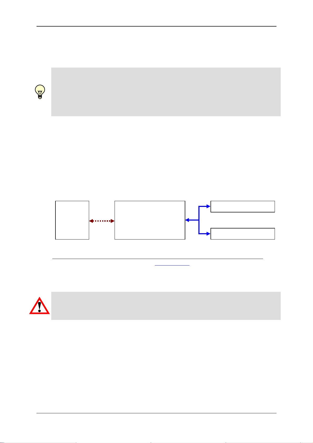
If the CSI-F-10 GSM radio module is operated with the aid of a PC modem via a GSM
mobile radio connection, communication occurs using a special protocol.
In this case the CSI-F-10 does not have an HSI address, because it is activated via the
special protocol for modem connections and only a point to point connection is possible
in this protocol.
If sensors are connected to the CSI-F-10, the GSM radio module can be transferred to
the pass-through mode. In the pass-through mode, the sensors can be accessed using
the normal HSI addresses "a" ... "z".
PC
(using
GSM
modem)
GSM Radio
GSM
Module
CSI-F-10
( No address )
Sensor (address a)
HSI
Sensor (address b)
For the GSM-Modem for the PC connection, we recommend the following devices:
-
"GS64 Terminal"; Manufacturer: CEP AG (www.cepag.de)
- "GPRS GSM Quadband Modem / USB"; Manufacturer: ConiuGo GmbH (www.coniugo.com)
Warning!
If the time of day or date of the GSM radio module is modified via a mobile radio
connection, then the new time is only visible at the next connection setup in CMWIN.
Time of day and date are however changed immediately in the CSI-F-10.
Status 29.01.2009 HYDAC ELECTRONIC GMBH Part.-Nr.: 669752
Page 45
GSM Radio Module CSI-F-10 Page 45
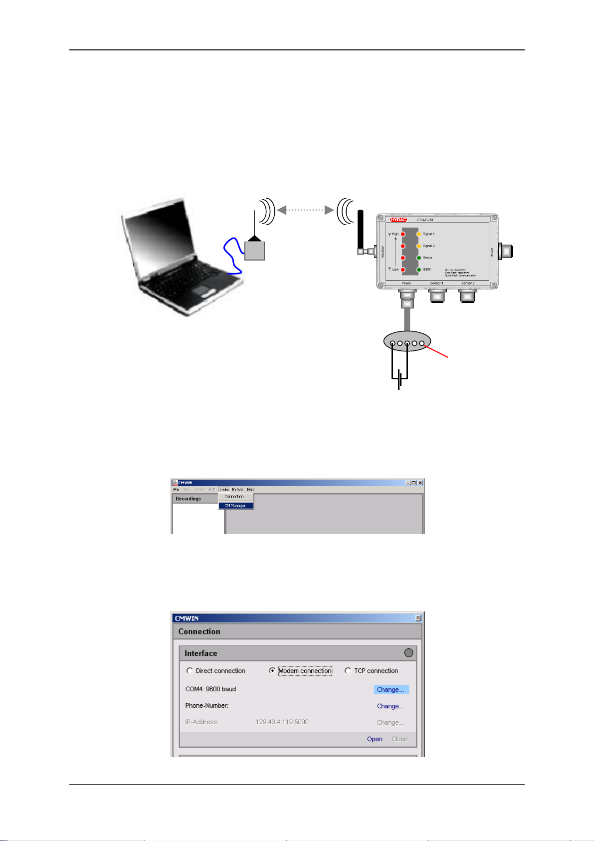
6.5.1 Device connection
• Connect your PC with a standard GSM modem and make sure the device is
ready for operation.
• Insert a valid SIM card into the CSI-F-10 GSM radio module
(see Chap. 6.1).
• Connect the voltage supply to the CSI-F-10 GSM radio module according to the
diagram.
GSM
1 2 3 4 5
PIN 5
Not to connect!
10.5..35 V DC / 3.5 A
6.5.2 Connection Setup
• Start the HYDAC PC software CMWIN
• In the Units Menu, select the "CM Manager" option.
• If the Connection window does not open automatically, select
"Connection" in the menu bar of the CM Manager.
• Select the option "Modem Connection" option in the window that opens.
• Click on "Change" in the top line to open the window for the interface settings.
Status 29.01.2009 HYDAC ELECTRONIC GMBH Part.-Nr.: 669752
Page 46

GSM Radio Module CSI-F-10 Page 46
• Make the corresponding preselection for the port settings in the window that
opens under Interface selection.
• Select the relevant port address and Baud rate (9600 for GSM) under Interface
settings.
• Click "Refresh" to update the interfaces marked under Interface selection in
terms of availability.
• Click on “OK“ to apply the modified settings or “Cancel“ to discard these
changes. In either case you will then return to the Connection window.
• Click on "Modify" in the Telephone number line to open the window for
inputting telephone numbers.
• Enter the telephone number of the SIM card mounted in the GSM module CSIF-10.
• In the Pin field enter the PIN code (if one has been assigned) for the SIM card
of the modem connected to the PC. If no PIN code has been assigned, then
leave the field empty.
• You can set up a list of telephone numbers (address book) under Telephone
list.
• Click on “OK“ to apply the entries or “Cancel“ to discard these changes. In
either case you will then return to the Connection window.
Telephone number of the
SIM card in the CSI-F-10
PIN number of the SIMcard in the PC modem
Status 29.01.2009 HYDAC ELECTRONIC GMBH Part.-Nr.: 669752
Page 47
GSM Radio Module CSI-F-10 Page 47
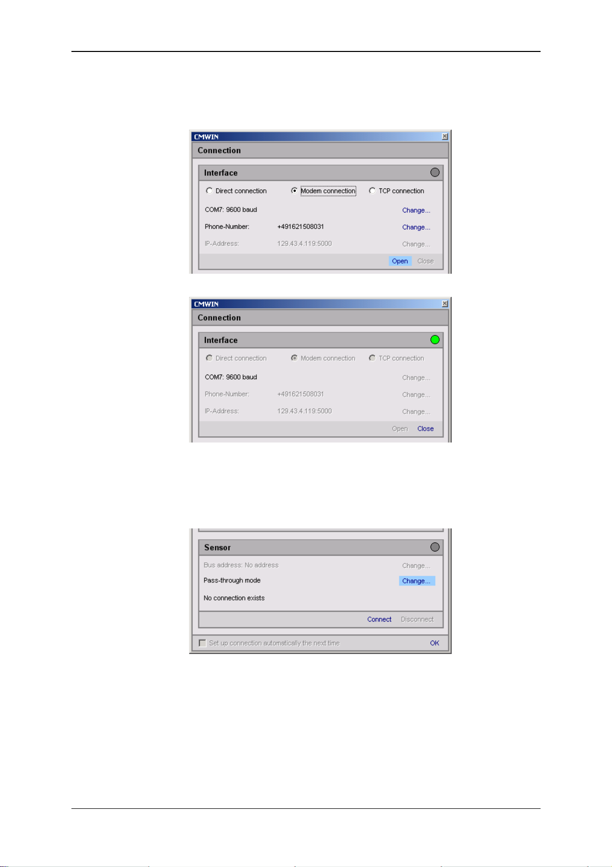
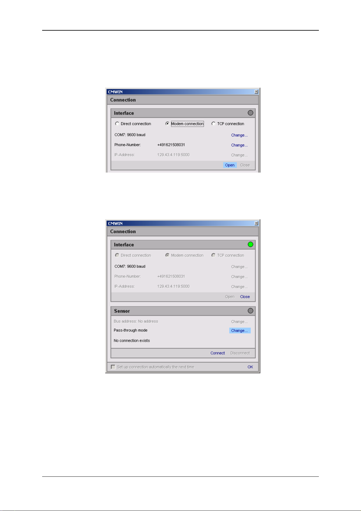
• Click on “Open” to open the selected interface. The opened interface is then
indicated by a green dot at the top right.
(Warning: The selection process can take up to a minute!)
• Click on "Change" to open the window for the pass-through mode and then
proceed according to the options described below.
Status 29.01.2009 HYDAC ELECTRONIC GMBH Part.-Nr.: 669752
Page 48

GSM Radio Module CSI-F-10 Page 48
6.5.2.1 Connecting to the CSI-F-10
• Select No address and then Switch off. The following message appears
• Confirm this with OK.
• Click on Connect to establish a link with the CSI-F-10.
• Click on Ok to establish the connection setup or on Disconnect to cancel the
connection setup.
Status 29.01.2009 HYDAC ELECTRONIC GMBH Part.-Nr.: 669752
Page 49

GSM Radio Module CSI-F-10 Page 49
• The following window opens after the connection has been successfully
established:
The menu structure and window properties of the CM Manager are explained below in
greater detail in Chapter 7 ff.
Status 29.01.2009 HYDAC ELECTRONIC GMBH Part.-Nr.: 669752
Page 50

GSM Radio Module CSI-F-10 Page 50
6.5.2.2 Connecting to the sensor by connection 1 (HSI address "a")
• Select Address a and then Switch on. The following message appears
• Confirm this with OK.
• Click on Connect to establish a link with the sensor.
• Click on Ok to continue with the connection setup or on Disconnect to cancel
the connection setup.
Status 29.01.2009 HYDAC ELECTRONIC GMBH Part.-Nr.: 669752
Page 51

GSM Radio Module CSI-F-10 Page 51
6.5.2.3 Connecting to the sensor by connection 2 (HSI address "b")
• Select Address b and then Switch on. Afterwards the following message
appears:
• Confirm this with OK.
• Click on Connect to establish a link with the sensor.
• Click on Ok continue with the connection setup or on Disconnect to cancel the
connection setup.
Status 29.01.2009 HYDAC ELECTRONIC GMBH Part.-Nr.: 669752
Page 52

GSM Radio Module CSI-F-10 Page 52
A
6.6 Voltage supply and communication via
Condition Monitoring Unit CMU 1000
If the CSI-F-10 GSM radio module is being operated on a Condition Monitoring Unit
CMU 1000 (see Chap. 3.2), the communication between the two units occurs via the
HSI Master Connection (power connection).
In this case, the CSI-F-10 must be switched into the pass through mode to be able to
access the CMU 1000 from the PC.
PC
GSM
GSM Radio
Module
CSI-F-10
HSI
CMU 1000
Sensor 1
Sensor 2
Address 'a'
Sensor n
Note!
If the CSI-F-10 is connected to a CMU 1000, then, apart from registering the authorized
telephone numbers (see Chap. 7.1.4.1), no settings must be made on the GSM radio
module. All activities come from the CMU 1000 in this case.
Also, an HSI address (in our example "a") must be assigned to the connected CMU
1000 and the interface must be set to "HSI".
6.6.1 Device Connection
• Connect a standard GSM modem to your PC and connect the CMU 1000 to the
GSM radio module CSI-F-10 as per the diagram below.
GSM
max. 30m
5 4 3 2 1
GND
+U
B
HSI
18..35 V DC / 3.5 A
ddress a
Status 29.01.2009 HYDAC ELECTRONIC GMBH Part.-Nr.: 669752
Page 53

GSM Radio Module CSI-F-10 Page 53
6.6.2 Connection Setup
• Start the HYDAC PC software CMWIN
• In the Units Menu, select the "CM Manager" option.
• If the Connection window does not open automatically, select
"Connection" in the menu bar of the CM Manager.
• Select the option "Modem Connection" option in the window that opens.
• Click on "Change" to open the window for the interface settings.
• Make the corresponding preselection for the port settings in the window that
opens under Interface selection.
• Select the relevant port address and Baud rate (9600 for GSM) under Interface
settings.
• Click "Refresh" to update the interfaces marked under Interface selection in
terms of availability.
• Click on “OK“ to apply the modified settings or “Cancel“ to discard these
changes. In either case you will then return to the Connection window.
• Click on "Change" to open the window for entering the telephone numbers.
Telephone number of the
SIM card in the CSI-F-10
PIN number of the SIMcard in the PC modem
• Enter the telephone number of the SIM card which is in the GSM radio module
CSI-F-10.
• In the Pin field enter the PIN code (if one has been assigned) for the SIM card
of the modem connected to the PC. If no PIN code has been assigned, then
leave the field empty.
Status 29.01.2009 HYDAC ELECTRONIC GMBH Part.-Nr.: 669752
Page 54
GSM Radio Module CSI-F-10 Page 54
• You can set up a list of telephone numbers (address book) under Telephone
list.
• Click on “OK“ to apply the entries or “Cancel“ to discard these changes. In
either case you will then return to the Connection window.
• Click on Open to open the selected interface. The open interface is indicated by
a green dot at the top right.
• Click on "Change" to open the window for the pass-through mode.
Status 29.01.2009 HYDAC ELECTRONIC GMBH Part.-Nr.: 669752
Page 55

GSM Radio Module CSI-F-10 Page 55
• Select the HSI address of the CMU 1000 connected to the CSI-F-10 in the
selection window (Address a in our example).
• Afterwards, click on Switch on in order to switch on the pass-through mode for
the selected channel.
• The following message appears:
• Confirm this with OK.
• Afterwards click on Connect to connect the PC to the CMU 1000 that is
connected with the CSI-F-10
Status 29.01.2009 HYDAC ELECTRONIC GMBH Part.-Nr.: 669752
Page 56

GSM Radio Module CSI-F-10 Page 56
• Successful establishment of the connection will be signaled as shown below:
• End the connection setup by confirming with OK.
Status 29.01.2009 HYDAC ELECTRONIC GMBH Part.-Nr.: 669752
Page 57

GSM Radio Module CSI-F-10 Page 57
7 Configuration Using CMWIN PC Software
Configuration of the CSI-F-10 and implementation of the basic settings can also be
carried out using the "CM Manager“ from a PC.
The "CM Manager" is a component part of the CMWIN HYDAC PC software, starting
with Version 3, and provides you with various tools and functions for the connecting,
configuring, parameterizing and outputting of CM devices.
7.1 Actions
7.1.1 Display Device Status
• Status
The "Status" indicates the current condition of the device. The individual
conditions can be be specified in greater detail via the following table.
Ready No active error present, device is ready for operation
Stand-By No active error present, but device is currently not ready for
operation; it may be that individual device functions are switched
off or the device is in a startup phase, etc.
Minor error A minor error is present which can be acknowledged.
Moderate error A medium-serious error is present, which may possibly be
eliminated by switching On/Off.
Serious error A serious error is present; the unit must be sent in to the
manufacturer.
• Status code
The "Status code" is dependent on the CM Program present in the device and
reflects the conditions of the Boolean output values used in the program.
For this, the Boolean output values are displayed from right to left in ascending
binary sequence, i.e. the lowest-value bit corresponds to the Boolean output
value 0.
Example:
0 = No Boolean output values used in the program
1 0 1 0 = Boolean output value 0 = 0 (LSB)
Boolean output value 1 = 1
Boolean output value 2 = 0
Boolean output value 3 = 1 (MSB)
• Status text
The "Status text" indicates whether or not a CM Program is available in the
device.
No script loaded No CM Program is available in the device.
Script is loaded A CM Program is available in the device.
Status 29.01.2009 HYDAC ELECTRONIC GMBH Part.-Nr.: 669752
Page 58

GSM Radio Module CSI-F-10 Page 58
7.1.2 Display Device Information
• ere the values of the following status parameters are displayed:
- Part numer
- Serial number
- Channel information
The channel information reflects the numberical output values from the CM
program. Channel 0 corresponds to the first numerical output value in the CM
Program, Channel 1 the second, etc.
The upper and lower limits and the units stored in the CM program are
displayed.
If no CM Program is available in the device, then the connected sensors will be
displayed at this point with sub-channels, measurement ranges and units.
The upper and lower limits and the units stored in the sensor are displayed.
Status 29.01.2009 HYDAC ELECTRONIC GMBH Part.-Nr.: 669752
Page 59

GSM Radio Module CSI-F-10 Page 59
7.1.3 Display Measured Values
• Here the results of the numerical output values from the CM program in the
device are displayed.
If no CM Program is available in the device, then the measured values of the
connected sensors will be displayed.
Status 29.01.2009 HYDAC ELECTRONIC GMBH Part.-Nr.: 669752
Page 60

GSM Radio Module CSI-F-10 Page 60
7.1.4 Performing a Dialog
Under this menu point, the following settings can be made and output:
Only if a CM program is active and
numerical and/or boolean input
values can be used in it!
7.1.4.1 Program settings
• Date / Time
Date [input actual date]
Time [input actual time of day]
Click on "Apply", to apply the settings. "Back" takes you back to the main
menu.
• GSM
IMEI [displays the IMEI no. of the device]
Own phone number [displays the own phone number]
Signal strength / % [displays the actual network intensity]
Network operator [displays the network operator of the SIM card]
PIN [input the PIN code of the SIM card *]
Click on "Apply", to apply the settings. "Back" takes you back to the main
menu.
* Inputting the PIN code is only necessary if the PIN request is not activated on the SIM card. To deactivate the
PIN code place the SIM card in a mobile telephone and follow the device menu to deactivate the PIN request!
Status 29.01.2009 HYDAC ELECTRONIC GMBH Part.-Nr.: 669752
Page 61

GSM Radio Module CSI-F-10 Page 61
• Permissions
Number [input telephone number with country code]
Text [allow written access]
You can input up to five telephone numbers which allow connection to the CSI-
F-10 and from which the device may receive enquiry text messages (SMS).
By placing a checkmark in the "Text" box, you are also allowing access by text
to the CSI-F-10 from this telephone number (change settings, transfer CM
program, update firmware, ...)
Click on "Apply", to apply the settings. "Back" takes you back to the main
menu.
Warning!
If no telephone numbers are input here, no subsequent communication via a GSM
mobile radio connection can take place.
7.1.4.2 Information
• General
Supply voltage / V [displays value of supply voltage]
Sensor 'a' [displays type sensor 'a']
Sensor 'b' [displays type sensor 'b']
Note [input descriptive note]
Write authorization [displays whether programming enable is set]
(see Chap. 6.2 Programming enable)
Click on "Apply", to apply the settings. "Back" takes you back to the main
menu.
Status 29.01.2009 HYDAC ELECTRONIC GMBH Part.-Nr.: 669752
Page 62

GSM Radio Module CSI-F-10 Page 62
7.1.4.3 CM Program
• Program
CM Program / Byte [accumulator requirement display in CM program]
CM Source text / Byte [accumulator requirement display in CM source text]
Active [displays whether a CM program is active]
"Back" takes you back to the main menu.
• Numerical input values
Here you can change the values of all the numerical input values used in the
CM program.
Click on "Apply", to apply the settings. "Back" takes you back to the main
menu.
• Boolean input values
Here you can change the status of all the Boolean input values used in the CM
program.
Click on "Apply", to apply the settings. "Back" takes you back to the main
menu.
Status 29.01.2009 HYDAC ELECTRONIC GMBH Part.-Nr.: 669752
Page 63

GSM Radio Module CSI-F-10 Page 63
7.1.5 Managing Configurations
Here you can generate and manage various configuration files. These configuration
files can, for example, be generated in series on a "Master" device and then loaded
on an unlimited number of other CSI-F-10.
The following configuration files can be generated and managed:
• Input values
• Information
• Permissions
• Program
• GSM
• Date / Time
Selection
target folder
- With Open you can display the contents of a configuration file listed in the lower
display field. Highlight the required file with a mouse click. You can print out the
file in the window that opens automatically.
- With Load you can transfer a configuration file (marked in the lower display field)
from the PC to the CSI-F-10. The following message appears after the
completion of the transfer:
- When you press Save, you generate a new configuration file or save a modified
one to the previously specified target folder.
- Press Delete to delete the configuration file in the target folder highlighted in the
lower display field.
- Press Refresh to update the display field for the configuration files. The specified
target folder will be selected again for this purpose.
This is necessary, e.g. when you copy or delete configuration files using
Windows Explorer. These changes will not be displayed in the folder until after
"Refresh" has been carried out in CMWIN.
- With Display you can display the particular "Actual Configuration" currently in the
connected CSI-F-10.
Status 29.01.2009 HYDAC ELECTRONIC GMBH Part.-Nr.: 669752
Page 64
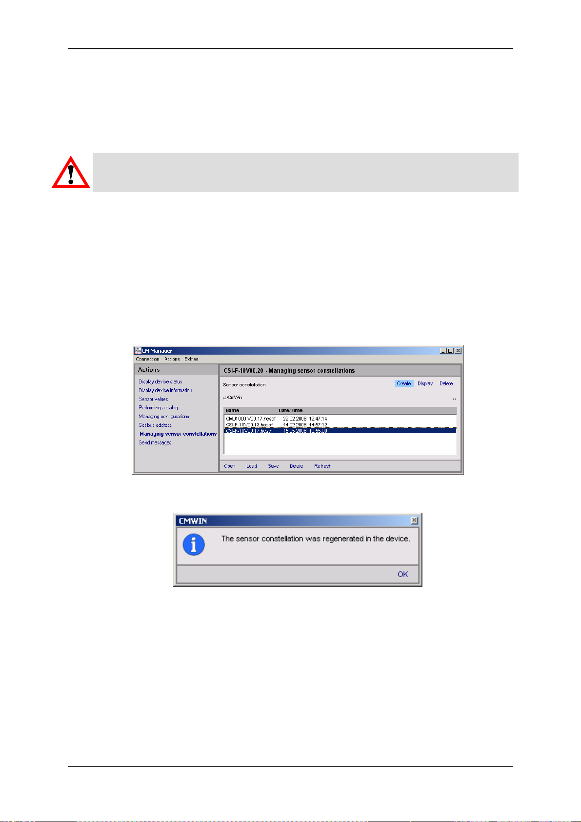
GSM Radio Module CSI-F-10 Page 64
7.1.6 Set bus address
The Set bus address function is a general CMWIN function, but which cannot be
used on a CSI-F-10 GSM radio module which is directly connected. A CSI-F-10
directly connected to a PC generally has the address "Bus master", which cannot
be altered.
Warning!
If you try to change the bus address of the CSI-F-10, an error message appears.
7.1.7 Managing sensor constellations
The sensor constellation is a monitoring instrument for the connected sensor
system, i.e. it continually compares the connected “Actual“ sensor system with the
specified “Target“ sensor system (see Chap. 8.1.5. Sensor constellation).
You can use this function to generate and manage various sensor constellation
files. These constellation files can, like the configuration files, be generated on a
"Master" device and then loaded onto an unlimited number of other CSI-F-10.
If no sensor constellation has yet been generated in the device then the following
window opens:
• You can generate a new sensor constellation in the device by pressing Create
(in the upper command bar). Afterwards, the following message appears:
• Press Display (in the upper command bar) to display the actual sensor
constellation currently in the device.
• Press Delete (in the upper command bar) to delete the actual sensor
constellation currently in the device.
All other functions in the lower command bar (Open, Load, Save, Delete, etc.) and
the selection of the target folder for saving the files are identical with Chapter 7.1.5
"Managing configurations".
Status 29.01.2009 HYDAC ELECTRONIC GMBH Part.-Nr.: 669752
Page 65

GSM Radio Module CSI-F-10 Page 65
7.1.8 Sending a text message
The "Send text message“ serves mainly to test the GSM mobile radio connection.
- In the Telephone number field, input the required number (this is independent of the
telephone numbers in Chap. 7.1.4.1 Permissions).
- In the Message field, input the message text.
• Click "Send" to send the message.
• By clicking on "Check status" you can track the progress of the message
transfer and check the connection.
Warning!
Text messages cannot be sent if the CSI-F-10 is being accessed via GSM connection.
This function is only available with cable connection (e.g. connection via CSI-B-2,
HMG 510, CMU 1000).
Status 29.01.2009 HYDAC ELECTRONIC GMBH Part.-Nr.: 669752
Page 66
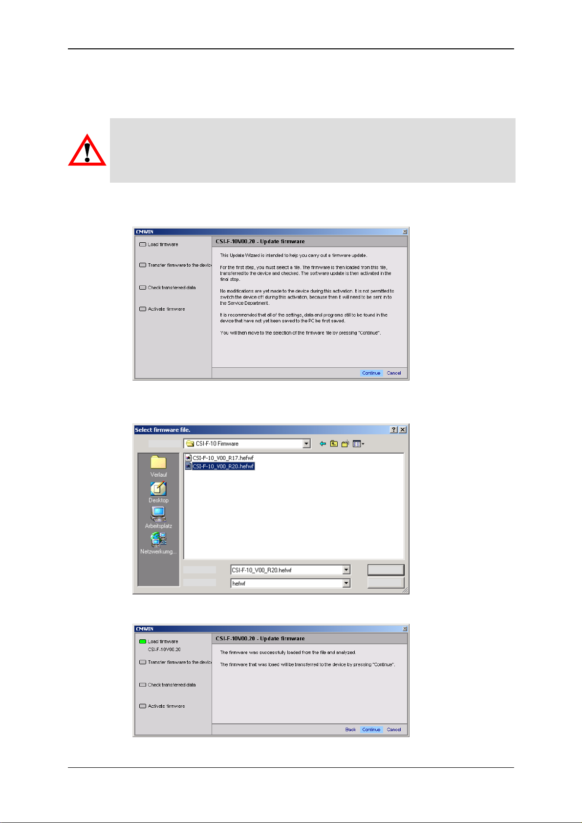
GSM Radio Module CSI-F-10 Page 66
7.2 Extras
7.2.1 Update Firmware
Caution
The voltage supply to the CSI-F-10 must not be interrupted during the firmware
update. If the voltage supply fails during the update process, then trouble-free
functioning can no longer be ensured and the device must be returned to HYDAC
SERVICE GMBH.
• After selecting this menu option, you can update the firmware of your CSI-F-10.
The following window opens for this purpose:
• Follow the instructions and confirm with Continue. In the window that opens,
select the corresponding Update file and click on Open.
Search in:
File name:
File type:
Open
Cancel
• Follow the instructions in the following window:
Status 29.01.2009 HYDAC ELECTRONIC GMBH Part.-Nr.: 669752
Page 67

GSM Radio Module CSI-F-10 Page 67
• Confirm with Continue to transfer the data to the CSI-F-10.
• By confirming with Continue, the data in the CSI-F-10 will be checked, and the
following two windows will appear one after the other:
• Confirm again with Continue to activate the new firmware in the device.
Status 29.01.2009 HYDAC ELECTRONIC GMBH Part.-Nr.: 669752
Page 68

GSM Radio Module CSI-F-10 Page 68
• In CMWIN the following window is the last one to open. Click on Close to return
to the CM Manager.
Afterwards, the CSI-F-10 reboots with the updated firmware. This breaks the
connection and this must be restored.
Note!
All settings, configurations, constellations and the CM program are retained and not
overwritten when the firmware is updated.
Status 29.01.2009 HYDAC ELECTRONIC GMBH Part.-Nr.: 669752
Page 69
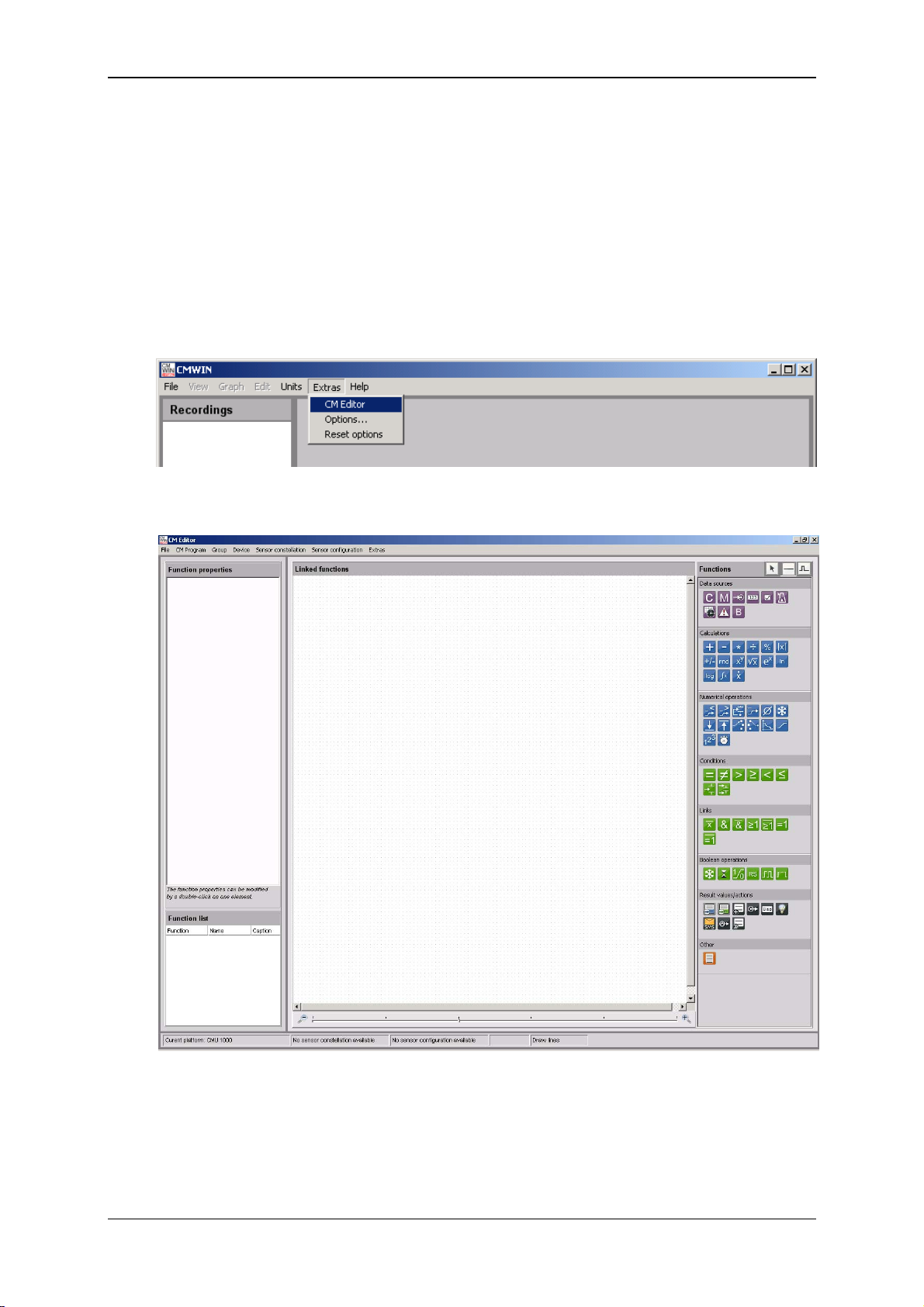
GSM Radio Module CSI-F-10 Page 69
8 CM Editor
The CSI-F-10 GSM radio module processes its program in continuous cycles. You
generate the program with the CM Editor then load it into the device.
The CM Editor is a constituent part of the HYDAC PC software CMWIN, Version 3 or
higher, and provides you with various tools and functions for designing, integrating and
testing your CM program.
To open the Editor, proceed as follows:
• Start the HYDAC PC software CMWIN
• In the Extras Menu, select the "CM Editor" option.
• The following screen opens:
The menu structure and window properties of the Editor are explained below in greater
detail:
Status 29.01.2009 HYDAC ELECTRONIC GMBH Part.-Nr.: 669752
Page 70

GSM Radio Module CSI-F-10 Page 70
8.1 Menu Bar
The menu bar of the CM Editor is tailored to the MS Windows user interface and
contains the following menu structure:
8.1.1 File
• With "New", you can establish for which platform (CM device) the CM program
is to be created before starting to create the CM program. The program
functions which are not available for the selected platform will be grayed out in
the Functions window and cannot be used during program generation.
• With "Platform", you can establish for which platform (CM device) the CM
program is to be created during the creation of a CM program. The program
functions which are not available for the selected platform will be grayed out in
the Functions window and cannot be used during program generation.
• Pressing "Open" allows you to open an already generated and stored CM
program. CM programs have the file extension *.hecmp. Select the required file
in the corresponding path.
• Select "Save" to save a CM program. If the recording has not yet been saved,
the “Save as…“ window will open. Enter the required file name in the
corresponding path.
• To save a file that has not yet been saved or to save a file that has already
been saved under a different name, select "Save as ...". Enter the required file
name in the corresponding path.
• To integrate an existing program that has already been saved into the current
program generation process, select "paste from file". Select the required file in
the corresponding path.
• Press "Print" to print out the content of the Linked functions window
(= program printout).
• Press "Exit" to close the CM Editor.
Status 29.01.2009 HYDAC ELECTRONIC GMBH Part.-Nr.: 669752
Page 71

GSM Radio Module CSI-F-10 Page 71
8.1.2 CM Program
• After "Display" is selected, a window opens listing all the functions used in the
CM program which is currently open, together with inscriptions and parameters.
The list can be printed out by selecting "Print".
Click on "Close“ to take you back to the CM Editor.
• With "Simulate", you can simulate and/or test the CM program that is currently
open. The Simulation window opens for this purpose. It is not necessary for
the CSI-F-10 to be connected for the simulation.
All of the input signals used in the CM program are listed one below the other
in the Name column in the left-hand part of the Simulation window.
You can assign a specific value to each input in the Input value column.
All of the actions used in the CM program are listed one below the other in the
Name column in the right-hand part of the Simulation window.
The current status of each action is displayed in the Value column.
The cycle number of the last status modification is displayed in the Cycle
column.
The date and time of the last status modification is displayed in the Time
column.
Status 29.01.2009 HYDAC ELECTRONIC GMBH Part.-Nr.: 669752
Page 72

GSM Radio Module CSI-F-10 Page 72
With "Perform cycle", you can start the simulation for a single processing
cycle and view the resulting status modifications of the actions afterwards.
With "Start autom. cycle" you can start a permanent, continuous program
simulation. You can change the input values however you like during the
simulation and observe the status modifications of the actions.
With "End autom. cycle" you can stop the permanent, continuous program
simulation.
Click on "Close“ to take you back to the CM Editor.
During the simulation, the assigned input values and action statuses are also
displayed in the Linked Functions window by means of corresponding
symbols.
Status 29.01.2009 HYDAC ELECTRONIC GMBH Part.-Nr.: 669752
Page 73
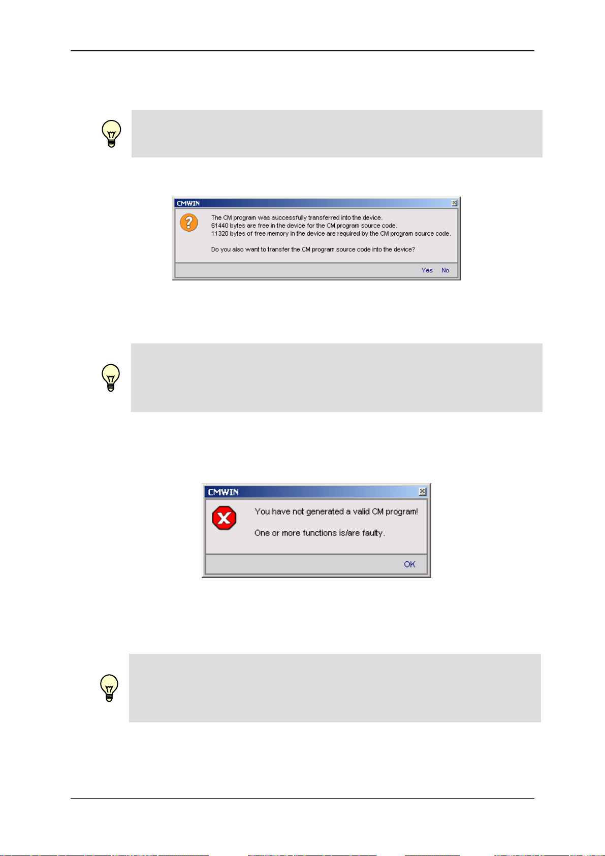
GSM Radio Module CSI-F-10 Page 73
• You can transfer the currently opened CM program to the CSI-F-10 with
"Transfer into device“.
Note!
Only error-free programs can be transferred into the CSI-F-10.
The following message appears after the program has been successfully
transferred:
Here you can select whether you also wish to transfer the source code of the
program into the CSI-F-10.
Note!
If the source code is also transferred into the CSI-F-10, then it is possible for it
to be read again by every other connected PC and modified! If the source
code is not also transferred into the CSI-F-10, then the program cannot be
uploaded by another PC.
The following message will appear if the CM program contains errors when
attempting transfer:
Eliminate the error(s) found in the CM program (see Chap. 8.2.2 "Function list“
window and Chap. 10. "Error messages“) and transfer the program again.
Note!
If you transfer a program and a power failure occurs during the transfer, then
the program will not be saved in the CSI-F-10 after power is restored. For that
reason, first save your program on the PC on which it was originally generated
or modified before making the transfer.
Status 29.01.2009 HYDAC ELECTRONIC GMBH Part.-Nr.: 669752
Page 74

GSM Radio Module CSI-F-10 Page 74
• You can transfer and then edit the CM program currently available in the CSI-F-
10 to your PC with "Receive from device". This will however only work if the
CM program source code from the original creator has also been transferred
into the CSI-F-10.
If no source code is available in the CSI-F-10, then the following message will
appear:
• The "Online Debugging" function is a tool for observing the CM program as
well as for finding, diagnosing and eliminating possible errors in the CM
program and/or in the connected peripherals.
The following prerequisites must be fulfilled for this purpose:
- The CSI-F-10 must be connected with the PC and the CMWIN software.
- The CM program opened in CMWIN and the one active in the CSI-F-10
must be identical.
If the "Online Debugging" mode is active, then the following values will be
displayed for the relevant functions:
- Measured values
- Constants
- Switching status of logical links
- Date and time when initiating the corresponding event
The display in "Online Debugging" mode is shown in the following illustration,
by way of example:
Status 29.01.2009 HYDAC ELECTRONIC GMBH Part.-Nr.: 669752
Page 75

GSM Radio Module CSI-F-10 Page 75
8.1.3 Grouping
• With Create grouping you can join several functions to make an cohesive unit
and move and copy these as a block.
First mark the functions to be grouped by enclosing them in a frame drawn
with the help of the cursor.
Afterwards, select “Group“ in the menu bar and then “Create grouping“ in the
drop-down menu that appears.
• Click on Cancel grouping to ungroup the functions which were linked together
in the group.
To do this, highlight the group concerned by clicking on any one of the
functions within the group.
Afterwards, select “Group“ in the menu bar and then “Cancel grouping“ in the
drop-down menu that appears.
8.1.4 Device
The "Connection“ function can be used to set up a connection between the PC and a
CSI-F-10 from the CM Editor.
The function is identical with the connection setup in the CM Manager. See Chap. 6.3.2
ff.
Status 29.01.2009 HYDAC ELECTRONIC GMBH Part.-Nr.: 669752
Page 76
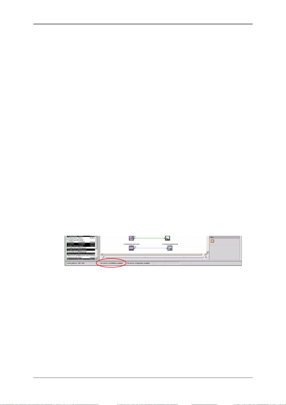
GSM Radio Module CSI-F-10 Page 76
8.1.5 Sensor constellation
For reliable system monitoring, ensure that exactly the same sensors that were
connected at the time the CSI-F-10 was configured are connected during operation.
The Sensor constellation is used for this purpose. The sensor constellation is a
monitoring instrument for the connected sensor system, i.e. it continually compares the
connected "Actual" sensor system and the specified "Reference" sensor system.
The sensor constellation is optional in the CSI-F-10 and not compulsory. If however a
sensor constellation has been saved, then the connected sensor system must match it.
When there is an activated sensor constellation, then an "incorrect" sensor connected
by mistake will be recognized, thus preventing a situation in which the CM program is
working with incorrect information.
A sensor constellation can be saved in files and loaded from files, and can be both
received and transferred by the CSI-F-10.
The constellation files all have the extension *.hescf.
The sensor constellation contains the following data:
- Quantity of connected sensors
- Quantity of subchannels for each connected sensor
- Status of each individual subchannel (active/inactive)
- Sensor class (analog / HSI / SMART)
- Units of the individual measured values
- Name of each sensor
- Device designation of each sensor
If a sensor constellation is available in the CM Editor, then you can use the correct
names in connection with the measurements during program generation. It will then be
the case that only those sensors and subchannels that are actually present will be
available and accessible for adjustment.
A status message at the lower edge of the window of the CM Editor indicates whether
or not a sensor constellation is available.
• With the function Apply from file, you can open a saved sensor constellation
file and use it in the CM Editor.
To do this, enter the corresponding path and file name in the window that opens
and then click on Open.
• With the function Apply from device, you transfer one of the sensor
constellations stored in the CSI-F-10 to your PC, after which you can use it in
the CM Editor.
Status 29.01.2009 HYDAC ELECTRONIC GMBH Part.-Nr.: 669752
Page 77

GSM Radio Module CSI-F-10 Page 77
• With Uninstall you delete the currently available sensor constellation in the CM
Editor, after which it is no longer available for further use when generating
programs.
No saved constellation files are deleted!
• To save a constellation file, select Saving to file. Enter the appropriate path
and required file name for this purpose in the window that opens.
• When the Display function is selected, a window opens in which the complete
sensor constellation is displayed.
Status 29.01.2009 HYDAC ELECTRONIC GMBH Part.-Nr.: 669752
Page 78

GSM Radio Module CSI-F-10 Page 78
8.1.6 Extras
• The following window opens when the function Options is selected:
The selection buttons at the right-hand edge of the window appear after clicking
in the respective selection field.
- In the Language field, you can select either German, English or French as the
CMWIN system language.
- In the field Working folder you define the path for saving the CMWIN files
(CM programs, recordings, constellation and configuration files, ...).
- In the field Name as inscription you define whether or not the particular
function name (e.g. Measured value 2, Action 4) is to be displayed as the
function inscription in the "Linked functions" window.
If "No" is selected, then you have the option of entering an inscription text
manually into the function parameters.
- In the field Frame group you define whether or not a frame is to be shown
around generated groups in the CM program.
- Clicking on OK applies the settings and returns you to the main CMWIN
window.
Pressing Cancel takes you back without applying any changes.
• By using the Reset Options function you can reset all the modified options and
settings to the standard settings.
• Select the Display cycle time function to open the following window and to
display the current cycle time of the CM program.
Example:
Status 29.01.2009 HYDAC ELECTRONIC GMBH Part.-Nr.: 669752
Page 79

GSM Radio Module CSI-F-10 Page 79
8.2 Window Divisions
The graphics interface of the CM Editor is divided into the following elements:
8.2.1 "Function Properties" Window
The properties of the functions currently selected in the CM program are displayed in
this window. These include:
• Function name (e.g. Action 2; Constant 5; Measured value 12)
• Function type (e.g. Constant, Measured value, Time Sensor)
• Specific properties (parameter settings)
• Comment
8.2.2 "Function List" Window
This window lists all the functions used in the CM program with the following
specifications:
• Function type (e.g. Constant, Measured value, Time sensor)
• Function name (e.g. Action 2; Constant 5; Measured value 12)
• Inscription (e.g. Working pressure N.O.K.)
8.2.3 "Linked Functions" Window
This window contains the actual CM program. The display can be zoomed in or out
with the scroll bar on the lower edge of the window.
8.2.4 "Functions" Window
This window contains all the functions available for program generation, sorted
according to:
• Data sources
• Calculations
• Numerical operations
• Conditions
• Links
• Boolean operations
• Result values/actions
• Other
Status 29.01.2009 HYDAC ELECTRONIC GMBH Part.-Nr.: 669752
Page 80

GSM Radio Module CSI-F-10 Page 80
9 CM Program Functions
A CM program consists of many individual functions that are linked with one another
and that are processed and evaluated cyclically.
9.1 General Information Concerning Functions
A function has Inputs, Outputs and Parameters. This means, for example, the function
"Median value" reads a numerical value at the input, forms a median value above it and
then displays this at the output. A parameter is used to define the amount of time for
which the calculation is rendered.
9.1.1 Inputs / Outputs
For most functions, the outputs change during the running time, depending on the
input. Functions are linked with one another in the Editor. This means, for example,
that the output of a function can be linked with the input of a different function. It is
possible to make one output dependent on several inputs, but not several outputs on
one input.
There are two types of inputs/outputs, depending on the value type: Numerical and
Boolean. A "Boolean output" can only be linked with a "Boolean input" and a numerical
output can only be linked with a "numerical input".
9.1.1.1 Numerical Values
A numerical value is a decimal number, i.e. a numerical value with an optional
plus/minus sign and any number of digits after the decimal point. It is accurate to 7-8
significant places. That means that with a value of 2 million (7 places in front of the
decimal point), the addition of a value of 0.001 (3 places after the decimal point) will not
alter the numerical value. One would need accuracy to at least 10 significant places for
it to be altered.
Numerical inputs/outputs and the corresponding connection lines are shown in blue.
9.1.1.2 Boolean Values
A Boolean value is a logical status. There are only 2 statuses: "true" or "1" and false or
"0".
Boolean inputs/outputs and the corresponding connection lines are shown in green.
Status 29.01.2009 HYDAC ELECTRONIC GMBH Part.-Nr.: 669752
Page 81

GSM Radio Module CSI-F-10 Page 81
9.1.2 Parameters
Parameters are defined in the Editor and do not change during the running time.
Exceptions to this are the input parameters which can be modified during the running
time in a menu on the CSI-F-10 or using a PC which is connected.
Parameters have one of the following types:
9.1.2.1 Numerical Parameters
A numerical parameter is a decimal number in accordance with the inputs/outputs.
9.1.2.2 Whole Number
A whole number is a natural number, i.e. it has no digits after the decimal point. As a
rule, no negative numbers are permitted either. Whole numbers are used for example
for numbering purposes.
9.1.2.3 Input List
An entry from a list is selected for the input list type. The quantity and the type of list
entries is dependent on the particular parameter.
9.1.2.4 Boolean Parameters
A Boolean parameter has, as already described in connection with the inputs/outputs,
only two logical statuses: "0" and "1". Nevertheless, it is not "0" and "1" that are set in
the Editor, but rather such terms as "No" or "Yes", "Inactive" or "Active", "Off" or "On",
depending on the context.
9.1.2.5 Character String
A character string is an arbitrary text, the length of which is usually limited. In addition,
any leading and subsequent empty spaces are usually removed automatically.
9.1.2.6 Values Table
A values table is a table with several values, whereby each value is positioned in a line
of its own.
Furthermore, it is also possible to enter value pairs. The individual values of a value
pair are then separated from one another with a colon ":".
9.1.2.7 Time of day
The time of the day is specified in the country-specific format that is set in Windows.
Status 29.01.2009 HYDAC ELECTRONIC GMBH Part.-Nr.: 669752
Page 82

GSM Radio Module CSI-F-10 Page 82
9.2 Data Sources
9.2.1 Numerical Constant
The Numerical Constant function supplies a numerical value which
is defined in the Editor and which does not change during the
Inputs: Outputs: y: (Numerical)
Parameters: p
9.2.2 Measured value
Inputs: Outputs: y: (Numerical)
Parameters: p
9.2.3 Digital Input
running time.
That means that the Value parameter entered in the Editor is output
during the running time at the output.
: Value (Numerical)
1
The Measured Value function provides the current measured value
of a connected sensor.
The Sensor connection parameter is used to define the sensor; the
channel of the sensor with Subchannel. If a connected sensor has
no subchannel, then no selection is possible at this point.
If a sensor constellation has been saved, then only the active
connections are displayed in the input lists for the Sensor
connection, each of them with the relevant sensor name. The
subchannels available for this sensor are then displayed at
Subchannel, each of them with name and unit.
If no sensor constellation is saved, then Ports "A" to "P" are offered
for selection at Sensor connection and Channels "1" to "32"
at Subchannel.
: Sensor connection (input list)
1
p
: Subchannel (input list)
2
The Digital input function supplies the status of a digital input.
The Input terminal parameter is used to define which digital input
port is used.
Inputs: Outputs: y: (Boolean)
Parameters: p
: Input terminal (input list)
1
Status 29.01.2009 HYDAC ELECTRONIC GMBH Part.-Nr.: 669752
Page 83

GSM Radio Module CSI-F-10 Page 83
9.2.4 Numerical Entry
The function Numerical input supplies a numerical value which can
be adjusted in the Parameters menu of the CM device. As an
alternative, it can also be set via a connected PC.
The Inscription parameter is used as a menu option in the input
menu for this purpose. The permitted input range runs from
-2,000,000.000 to +2,000,000.000.
Changes which are carried out in the CM device during running time
are retained even after the device is switched off. Once the CM
program is transferred into the CM device for the first time, the value
set under Start value is used until the first change.
Inputs: Outputs: y: (Numerical)
Parameters: p
: Starting value (Numerical)
1
p
: Inscription (character string)
2
9.2.5 Boolean Entry
The Boolean input function supplies a Boolean value, which can be
set in the Parameters menu of the CM device.
As an alternative, it can also be set via a connected PC.
The Inscription parameter is used as a menu option in the input
menu for this purpose. Input is accomplished on the CM device by
selecting "Yes" or "No".
Changes which are carried out in the CM device during running time
are retained even after the device is switched off. Once the CM
program is transferred into the CM device for the first time, the value
set under Start value is used until the first change.
The Functionality parameter defines how the input is interpreted.
The following settings are possible:
Switch
A menu option is generated on the CM device with which the input
value can be switched on or off. This functionality is used to activate
certain paths in the evaluation logic.
Key
When the value on the CM device is switched on, then only one
impulse is generated in the evaluation logic and the option switches
itself off in the menu again immediately. A key function is simulated,
so to speak. This functionality can be used to trigger events in the
evaluation logic.
Inputs: Outputs: y: (Boolean)
Parameters: p
: Starting value (Boolean)
1
p
: Inscription (character string)
2
p
: Functionality (entry list)
3
Status 29.01.2009 HYDAC ELECTRONIC GMBH Part.-Nr.: 669752
Page 84

GSM Radio Module CSI-F-10 Page 84
9.2.6 Time Sensor
The Time sensor is a function which generates a pulse at an
adjustable interval (e.g. every minute, every 5 minutes), thus setting
its Boolean output to "1" for a cycle and then back to "0".
The following settings are possible for the Interval parameter:
• 1; 2; 5; 10; 15; 30 Seconds,
• 1; 2; 5; 10; 15; 30 Minutes,
• 1; 2; 6; 12; 24 Hours.
At the same time the output pulse is always synchronized with the
time of day. If, for example, "6 hours" is set, then a pulse will be
generated at 0600 HRS, 1200 HRS, 1800 HRS and 2400 HRS.
If a pulse is required at particular times of the day, then you should
use a clock timer with a downstream pulse generator instead of a
time sensor (see Chap. 9.8.6).
Inputs: Outputs: y: (Boolean)
Parameters: p
: Interval (input list)
1
9.2.7 Clock Timer
The Clock timer is a function which switches on its Boolean output at
a certain time during a month and then switches it off again at a
different point in time.
The switch-on time is set using the parameters Switch-on day and
Switch-on time, while the switch-off time is set using the parameters
Switch-off day and Switch-off time.
A weekday "Monday" to "Sunday" can be set. The setting "Daily" is
also possible. The "Daily" setting is only possible if both days are set
to "Daily". The Editor prevents erroneous inputs: If, for example, the
switch-on day is changed from "Monday" to "Daily", then the switchoff day is automatically set to "Daily".
If switch-on time and switch-off time are identical, then the output
will be switched on for precisely this specified second.
If only one pulse is required, i.e. if the output in intended to be set for
exactly one cycle to "1" and then back to "0", then use a
downstream pulse generator (see Chap. 9.8.6).
Inputs: Outputs: y: (Boolean);
Parameters: p
: Switch-off day (input list)
1
p
: Switch-off time (time of day)
2
p
: Switch-on day (input list)
3
p
: Switch-on time (time of day)
4
Status 29.01.2009 HYDAC ELECTRONIC GMBH Part.-Nr.: 669752
Page 85

GSM Radio Module CSI-F-10 Page 85
9.2.8 Error Event
Error handling can be implemented with the function Error event.
The Boolean output is switched to "1" when an error condition is
present. The output is switched back to "0" if the error disappears.
The type of error event can be set with the Event parameter.
The following events are possible:
Below signal range
A sensor has a cable break, for example
Above signal range
The signal of one sensor is above the signal range
Incorrect sensor constellation
There is either no sensor, or an incorrect sensor connected to one
sensor connection port.
Numerical error
An error occured during a calculation, e.g. division by 0 or square
root of a negative number, logarithm of 0, etc.
Cycle time exceeded
The set cycle time was exceeded.
Inputs: Outputs: y: (Boolean)
Parameters: p
: Event (input list)
1
9.2.9 Boolean Constants
The Boolean Constant function supplies a Boolean value which is
defined in the Editor and which does not change during the running
time. That means that the parameter entered in the Editor is output
during the running time at the output.
Inputs: Outputs: y: (Boolean)
Parameters: p
: Value (Boolean)
1
Status 29.01.2009 HYDAC ELECTRONIC GMBH Part.-Nr.: 669752
Page 86

GSM Radio Module CSI-F-10 Page 86
9.3 Numerical Calculations
9.3.1 Addition
The Addition function returns the sum of the two input values at the
output:
Inputs: x
Outputs: y: (Numerical)
Parameters: -
9.3.2 Subtraction
Inputs: x
Outputs: y: (Numerical)
Parameters: -
9.3.3 Multiplication
y = x1 + x
2
: (Numerical)
1
x
: (Numerical)
2
The Subtraction function returns the difference between the two
input values at the output:
y = x1 - x
2
: (Numerical)
1
x
: (Numerical)
2
The Multiplication function returns the product of the two input
values at the output:
y = x1 * x
2
Inputs: x
: (Numerical)
1
x
: (Numerical)
2
Outputs: y: (Numerical)
Parameters: -
9.3.4 Division
The Division function returns the quotient of the two input values at
the output:
Inputs: x
Outputs: y: (Numerical)
Parameters: -
y = x1 / x
2
: (Numerical)
1
x
: (Numerical)
2
Status 29.01.2009 HYDAC ELECTRONIC GMBH Part.-Nr.: 669752
Page 87
GSM Radio Module CSI-F-10 Page 87
9.3.5 Division Remainder
The Division remainder function returns the division remainder (the
modulo) of the two input values at the output. The division remainder
is determined by performing a whole number division x
/ x2 and
1
outputting the remainder of this division as output value.
If the input x1 counts upward, e.g. sequentially by 1, and the input x
is 5, then the output will count around from 0 to 4.
Inputs: x
: (Numerical)
1
x
: (Numerical)
2
Outputs: y: (Numerical)
Parameters: -
9.3.6 Absolute Value
The Absolute value function returns the input value without a
plus/minus sign at the output:
y = |x|
Inputs: x: (Numerical)
Outputs: y: (Numerical)
Parameters: -
9.3.7 Change of Algebraic Sign
2
The Change of sign function returns the inverse input value at the
output:
y = -x
Inputs: x: (Numerical)
Outputs: y: (Numerical)
Parameters: -
9.3.8 Rounding
The Rounding function returns the rounded input value at the output.
With this function, it is possible not only to round to whole decimal
Inputs: x: (Numerical)
Outputs: y: (Numerical)
Parameters: p
places, but also to whole-number multiples of a step.
The size of the step is specified in the Step parameter.
If the step size is 20, for example, then all values between -10 and
10 will be rounded off to 0, all values between 10 and 30 to 20, and
so on.
: Step (Numerical)
1
Status 29.01.2009 HYDAC ELECTRONIC GMBH Part.-Nr.: 669752
Page 88

GSM Radio Module CSI-F-10 Page 88
9.3.9 Raising to a Higher Power
The Raising to a higher power function supplies the power of the
input value at the output.
The exponent is set using the Exponent parameter.
Inputs: x: (Numerical)
Outputs: y: (Numerical)
Parameters: p
: Exponent (Numerical)
1
9.3.10 Square Root
The Square root function supplies the square root of the input value
at the output.
If the input value is negative, then the value 0 will be supplied at the
output and an error flag will be set. One can react to this situation
with the Error event function (see Chap. 9.2.8).
If it is possible for a negative input to occur in practice, then you
should structure the corresponding behavior in accordance with your
preferences with the functions Absolute value, If-then-else and Less
than (see Chap. 9.3.6, 9.4.4 and 9.6.5).
Inputs: x: (Numerical)
Outputs: y: (Numerical)
Parameters: -
9.3.11 Power at Base e
The Power at base e function supples the power at base e at the
output.
The input value is used as the exponent.
Inputs: x: (Numerical)
Outputs: y: (Numerical)
Parameters: -
9.3.12 Natural Logarithm
The Natural logarithm function supplies the logarithm of the input
value at base e at the output.
Inputs: x: (Numerical)
Outputs: y: (Numerical)
Parameters: -
If the input value is negative or 0, then the value 0 will be supplied at
the output and an error flag will be set. One can react to this
situation with the Error event function (see Chap. 9.2.8).
If it is possible for a negative input to occur in practice, then you
should structure the corresponding behavior in accordance with your
preferences with the functions Absolute value, If-then-else and Less
than (see Chap. 9.3.6, 9.4.4 and 9.6.5).
Status 29.01.2009 HYDAC ELECTRONIC GMBH Part.-Nr.: 669752
Page 89

GSM Radio Module CSI-F-10 Page 89
9.3.13 Decade Logarithm
The Decade logarithm function supplies the logarithm of the input
value at base 10 at the output.
If the input value is negative or 0, then the value 0 will be supplied at
the output and an error flag will be set. One can react to this
situation with the Error event function (see Chap. 9.2.8).
If it is possible for a negative input to occur in practice, then you
should structure the corresponding behavior in accordance with your
preferences with the functions Absolute value, If-then-else and Less
than (see Chap. 9.3.6, 9.4.4 and 9.6.5).
Inputs: x: (Numerical)
Outputs: y: (Numerical)
Parameters: -
9.3.14 Integral
The Integral function supplies the integral of the input value over
time at the output. The output is always calculated with the unit of
Inputs: x
Outputs: y: (Numerical)
Parameters: p
seconds. This means that the input value 6 causes the output to
increase every second by 6. The trapezoidal rule is applied to make
the calculation.
The function still has a Boolean reset input. If the value "1" is
pending there, then the value "0" will be set up at the output.
Furthermore, the integral function also has an automatic anti-wind-
up mechanism. It is with this that a parameterizable Lower limit and
Upper limit are set for the output.
This function adopted from control engineering has the following
background:
If a control variable is not achieved, then the I ratio continues to
integrate further. The controller then may require under certain
circumstances a very long time to exit this range again if the
actuating variable reverses its sign. This can lead to very unstable
behavior.
: Input value (Numerical)
1
x
: Reset input (Boolean)
2
: Lower limit (Numerical)
1
p
: Upper limit (Numerical)
2
Status 29.01.2009 HYDAC ELECTRONIC GMBH Part.-Nr.: 669752
Page 90

GSM Radio Module CSI-F-10 Page 90
9.3.15 Differential Quotient
The Differential quotient function supplies the derivation of the input
value over time at the output. The output is always calculated with
Inputs: x
Outputs: y: (Numerical)
Parameters: p
the unit of seconds. This means that an increase of the input value
from 5 to 6 in one second will yield an output value of 1.
The differential quotient is formed and filtered numerically by the
difference quotient. This filtering is necessary for the following
reasons:
In view of the fact that the input values usually arise from a
quantized measured value, e.g. in connection with the digitization of
an analog quantity, these values will have a so-called quantization
noise. This means that the digitization causes the value to fluctuate
in terms of the resolution. For example, for 12 bit resolution, a value
of 600 bar which has been expressed in 12 bit resolution, fluctuates
back and forth by 0.15 bar. If the differential quotient is now
generated every millisecond, this quantization noise is amplified by a
factor of 1000. This means that, without filtering, the output would
jump back and forth between + and - 150 bar/s.
The filter can be set with the Filtering parameter. The setting
corresponds thereby to the time range during which the filtering
takes place. However, a pure median value formation will not be
used as a filter, but rather a special algorithm instead.
The following settings are possible:
• switched off, • 200 ms, • 1 second • 5 seconds.
: (Numerical)
1
: Filtering (entry list)
1
Status 29.01.2009 HYDAC ELECTRONIC GMBH Part.-Nr.: 669752
Page 91

GSM Radio Module CSI-F-10 Page 91
9.4 Numerical Operations
9.4.1 Minimum
The Minimum function supplies the smaller of the two input values at
the output.
Inputs: x
Outputs: y: (Numerical)
Parameters: -
9.4.2 Maximum
Inputs: x
Outputs: y: (Numerical)
Parameters: -
9.4.3 Limit
: (Numerical)
1
x
: (Numerical)
2
The Maximum function supplies the larger of the two input values at
the output.
: (Numerical)
1
x
: (Numerical)
2
The Limit function limits the input value x
the output.
The two limits are set by the input values x2 and x3. If x1 is less than
x
, then x2 will be output, if x1 is greater than x3, then x3 will be
2
output, otherwise x
.
1
Inputs: x
1:
x
: Lower limit (Numerical)
2
x
: Upper limit (Numerical)
3
Input value (Numerical)
Outputs: y: (Numerical)
Parameters: -
9.4.4 If - then - else
The function If-Then-Else has two numerical inputs x
as a Boolean input x
If the Boolean input value is "1", then the input value of x1 is output
at the output, otherwise the value of x
Inputs: x
: (Numerical)
1
x
: (Numerical)
2
x
: (Boolean)
3
Outputs: y: (Numerical)
Parameters: -
.
3
, and makes it available at
1
and x2 as well
1
.
2
Status 29.01.2009 HYDAC ELECTRONIC GMBH Part.-Nr.: 669752
Page 92
GSM Radio Module CSI-F-10 Page 92
9.4.5 Median Value
The Median value function outputs the arithmetical median value of
the input values over an adjustable time range.
The time range is set in seconds using the Time parameter.
The median value is formed according to the "Repeating Average"
procedure. This means that, when the time setting is "2 seconds",
for example, the input values are compiled for 2 seconds, then
averaged and output at the output. The next median value interval
begins after that. The output value pauses on the last median value.
Inputs: x: Input value (Numerical)
Outputs: y: Median value (Numerical)
Parameters: p
: Time (Numerical)
1
9.4.6 Note Value
The Note value function is used to hold on to certain values (to
freeze them). It has one numerical and one Boolean input.
If the Boolean input value is "1", then the numerical input value is
output at the output. If the Boolean input value is "0", then the last
output value continues to be output.
If the value is only to be applied for one flank of the Boolean input,
then you can put the function Pulse generation upstream from it (see
Chap. 9.8.6).
Inputs: x
: Input value (Numerical)
1
x
: Switch value through (Boolean)
2
Outputs: y: (Numerical)
Parameters: -
9.4.7 Note Minimum
The Note mini mum function outputs the smallest value that the input
value has yet reached.
If the input value is greater than the output value, then the output
value remains unchanged. If the input value is less, then the output
value will be reset.
The minimum can be reset with the Boolean input x2. The input
value will be applied directly at the output for as long as this input is
"1".
Inputs: x
: Input value (Numerical)
1
x
: Reset (Boolean)
2
Outputs: y: (Numerical)
Parameters: -
Status 29.01.2009 HYDAC ELECTRONIC GMBH Part.-Nr.: 669752
Page 93

GSM Radio Module CSI-F-10 Page 93
9.4.8 Note Maximum
The Note maximu m function outputs the largest value that the input
value has yet reached.
If the input value is less than the output value, then the output value
remains unchanged. If the input value is greater, then the output
value will be reset.
The maximum can be reset using the Boolean input x2. The input
value will be applied directly at the output for as long as this input is
"1".
Inputs: x
: Input value (Numerical).
1
x
: Reset (Boolean)
2
Outputs: y: (Numerical)
Parameters: -
9.4.9 Tabular Value
With the function Tabular value, the output value is obtained from a
parameterized number table. The input value functions as a number
Inputs: x: Index of the selected tabular value (Numerical)
Outputs: y: Selected value (Numerical)
Parameters: p
of the table entry at the same time.
If the whole number value of the input is 0 or less, then the first
value of the table will be output; if it is 1, then the second value; and
so on up to the last tabular value. If the input value is greater than
the number of tabular entries, then the last table entry will be output.
As a basic rule, the input value will be rounded to a whole number.
The table is defined using the Table parameter. Each value must
have a line of its own at the time of entry. Empty lines are removed
automatically. The number of values will also be defined
automatically on the basis of the available lines. It must be between
2 and 20.
The Tabular value function can be used for example as a
downstream element of a division remainder in order to simulate
various values one after the other (see Chap. 9.3.5).
: Table (values table)
1
Status 29.01.2009 HYDAC ELECTRONIC GMBH Part.-Nr.: 669752
Page 94

GSM Radio Module CSI-F-10 Page 94
9.4.10 Tabular Index
The Tabular index function is the counterpart to the Tabular value
function. The input value is sorted into a parameterizable numerical
table, which must be organized in order of increasing values, and
the number of the tabular entry is output.
If, for example, the first tabular entry is 4 and the second is 7.8, then
a 0 will be output for all input values less than 4, the value 1 will be
output for all values between 4 and 7.8, and the value 2 for all
values greater than 7.8.
The table is defined using the Table parameter. Each value must
have a line of its own at the time of entry. Empty lines are removed
automatically. The number of values will also be defined
automatically on the basis of the available lines. It must be between
2 and 20.
This function can be used for flexible range definition. Thus, for
example, limits can be defined in the table when a value is normal,
suspicious, critical and very critical.
Inputs: x: Value in the table (Numerical).
Outputs: y: Index of the value / Value range (Numerical).
Parameters: p
: Table (values table)
1
9.4.11 Characteristic Curve
The Characteristic curve function is used to convert input values
from one range into another. The conversion can be subdivided into
various segments through the specification of up to 20 nodes.
The Table parameter is used to specify the nodes. Each value pair
is in a different line in the table. The values for x and y are separated
by a colon. The x values must be listed in ascending order. No x
value may appear more than once. Empty lines are removed
automatically. The number of values will also be defined
automatically on the basis of the available lines. It must be between
2 and 20.
The ranges between the nodes are interpolated linearly; the values
outside the nodes are extrapolated from the last segment. A
limitation is easy to set up by simply setting another node nearby
that has the same y value. If for example the range of 0 to 450 is to
be converted to percent and at the same time limited to 0 and 100,
then this is accomplished with the following value pairs:
-1: 0
0: 0
450: 100
451: 100
Inputs: x: X value of the characteristic curve (Numerical).
Outputs: y: Function value from the characteristic curve (Numerical)
Parameters: p
: Table (values table)
1
Status 29.01.2009 HYDAC ELECTRONIC GMBH Part.-Nr.: 669752
Page 95

GSM Radio Module CSI-F-10 Page 95
9.4.12 Ramp
The Ramp function is used to prevent rapid value changes. Under
stable conditions, the input value is shown at the output. Changes of
Inputs: x: (Numerical)
Outputs: y: (Numerical)
Parameters: p
the input value are however not relayed directly to the output, but
only in small steps instead. Like a slope, so to speak. Different
slopes can be defined for positive and negative value modifications
at the same time.
The parameters Falling ramp and Rising ramp are used to specify
the maximum permissible value changes per second.
If for example the value 5 is set for Rising ramp and the input value
jumps from 0 to 100, then the output will be only slowly increased,
and it will take 20 seconds for the output value to reach 100.
: Falling ramp (Numerical)
1
p
: Rising ramp (Numerical)
2
Status 29.01.2009 HYDAC ELECTRONIC GMBH Part.-Nr.: 669752
Page 96

GSM Radio Module CSI-F-10 Page 96
9.5 Counting Functions
9.5.1 Count Pulses
The Count pulses function has three Boolean inputs and one
numerical output. If the Counting input has the value "1", then the
Inputs: x
Outputs: y: Count value (Numerical)
Parameters: -
9.5.2 Stop Watch
changes from "0" to "1" at the Pulses input will be counted and the
count value will be set at the output. If the Reset input is at "1", then
the count value, and thus the output as well, will be "0".
Flexible counting structures can thus be obtained by placing the
Pulse generation function upstream (see Chap. 9.8.6). The
placement of a downstream Note value function (see Chap. 9.4.6)
also makes it possible to provide a counter with an interim status.
: Pulses (Boolean)
1
x
: Counting (Boolesch)
2
x
: Reset (Boolean)
3
The Stop watch function has two Boolean inputs and one numerical
output. If the Start/Stop input has the value "1", then the seconds will
be counted and the time will be applied at the output. If the Reset
input is at "1", then the time, and thus the output as well, will be "0".
The behavior at the output can be controlled with the Output
parameter.
Two settings are possible:
Current time
The output value is the current number of seconds counted.
Stopped time
The output value is not the current quantity, but rather the most
recently measured quantity. This means that the current count is set
to the output whenever the time is stopped with the Start/Stop input.
Flexible time measurement structures can thus be obtained by
placing the Pulse generation function upstream (see Chap. 9.8.6).
Inputs: x
: Start/Stop (Boolean)
1
x
: Reset (Boolean)
2
Outputs: y: (Numerical)
Parameters: p
: Output (entry list)
1
Status 29.01.2009 HYDAC ELECTRONIC GMBH Part.-Nr.: 669752
Page 97

GSM Radio Module CSI-F-10 Page 97
9.6 Numerical Conditions
9.6.1 Equals
The Equals function compares two numerical input values for
equivalence and outputs a "1" at its Boolean output if the values are
Inputs: x
Outputs: y: (Boolean)
Parameters: p
9.6.2 Does not Equal
equivalent, otherwise a "0".
With the Precision parameter, you can adjust how precise the
comparison is. For this the following explanation:
In view of the fact that numerical values are presented on computers
as floating point numbers with finite precision, normal comparisons
usually fail. Thus, for example, the finite precision of 2/6 is not
necessarily the same as the result of 1/3. The difference goes to 8
decimal places, but nonetheless the two values are not recognized
as being equivalent.
The point at which one needs to break off the comparison of
numbers varies from case to case. It is for that reason that you have
the option of controlling the precision of the comparison.
If you specify 0.01 for precision, for example, then the numbers
12.453 and 12.458 will still be recognized as equivalents to one
another, because the difference is less than 0.01.
: (Numerical)
1
x
: (Numerical)
2
: Precision (Numerical)
1
The Does not equal function compares two numerical input values
and outputs a "1" at its Boolean output if the values are not equal,
otherwise a "0".
For the Precision parameter, see the explanation in the Equals
function (Chapter 9.6.1).
Inputs: x
: (Numerical)
1
x
: (Numerical)
2
Outputs: y: (Boolean)
Parameters: p
: Precision (Numerical)
1
Status 29.01.2009 HYDAC ELECTRONIC GMBH Part.-Nr.: 669752
Page 98

GSM Radio Module CSI-F-10 Page 98
9.6.3 Greater than
The Greater than function compares two numerical input values and
outputs a "1" at its Boolean output if value x
otherwise a "0".
is greater than x2,
1
In view of the fact that numerical values are presented on computers
as floating point numbers with finite precision, it is difficult to make
decisions in border ranges. (See the explanation in Chapter 9.6.1,
Equals function). This is however usually irrelevant in everyday
usage, because the accuracy is to 8 significant decimal places.
When however it is important that a precise decision be made for a
border range, then you can install the Rounding function upstream
(see Chap. 9.3.8).
Inputs: x
: (Numerical)
1
x
: (Numerical)
2
Outputs: y: (Boolean)
Parameters: -
9.6.4 Greater than or Equal to
The Greater than or equal to function compares two numerical input
values and outputs a "1" at its Boolean output if value x
than or equal to x
, otherwise a "0".
2
For more on the subject of precision, please see the explanations in
the Greater than function (see Chapter 9.6.3).
Inputs: x
: (Numerical)
1
x
: (Numerical)
2
Outputs: y: (Boolean)
Parameters: -
9.6.5 Less than
The Less than function compares two numerical input values and
outputs a "1" at its Boolean output if value x
Inputs: x
Outputs: y: (Boolean)
Parameters: -
otherwise a "0".
For more on the subject of precision, please see the explanations in
the Greater than function (see Chapter 9.6.3).
: (Numerical)
1
x
: (Numerical)
2
is greater
1
is less than x2,
1
Status 29.01.2009 HYDAC ELECTRONIC GMBH Part.-Nr.: 669752
Page 99

GSM Radio Module CSI-F-10 Page 99
9.6.6 Less than or Equal to
The Less than or equal to function compares two numerical input
values and outputs a "1" at its Boolean output if value x
or equal to x
, otherwise a "0".
2
is less than
1
For more on the subject of precision, please see the explanations in
the Greater than function (see Chapter 7.6.3).
Inputs: x
: (Numerical)
1
x
: (Numerical)
2
Outputs: y: (Boolean)
Parameters: -
9.6.7 Within
The Within function compares three numerical input values and
outputs a "1" at its Boolean output if value x
to x
, and smaller than or equal to x3, otherwise a "0".
2
is greater than or equal
1
For more on the subject of precision, please see the explanations in
the Greater than function (see Chapter 9.6.3).
Inputs: x
: (Numerical)
1
x
: (Numerical)
2
x
: (Numerical)
3
Outputs: y: (Boolean)
Parameters: -
9.6.8 Outside
The Outside function compares three numerical input values and
outputs a "1" at its Boolean output if value x
greater than x
, otherwise a "0".
3
For more on the subject of precision, please see the explanations in
the Greater than function (see Chapter 9.6.3).
Inputs: x
: (Numerical)
1
x
: (Numerical)
2
x
: (Numerical)
3
Outputs: y: (Boolean)
Parameters: -
is smaller than x2 or
1
Status 29.01.2009 HYDAC ELECTRONIC GMBH Part.-Nr.: 669752
Page 100

GSM Radio Module CSI-F-10 Page 100
9.7 Boolean Links
9.7.1 Not
The Not function supplies the negated Boolean input value at its
Boolean output.
Inputs: x: (Boolean)
Outputs: y: (Boolean)
Parameters: -
9.7.2 And
Inputs: x
Outputs: y: (Boolean)
Parameters: -
9.7.3 Not - And
If x = "0", then a "1" is output, otherwise a "0".
The And function links the two Boolean inputs with the "and"
operation and supplies the result to its Boolean output.
The output is then "1" only if both inputs are "1", otherwise it is "0".
The following log table makes this function clear.
x
x
1
y
2
0 0 0
0 1 0
1 0 0
1 1 1
: (Boolean)
1
x
: (Boolean)
2
The Not - And function links the two Boolean inputs with the "nand"
operation and supplies the result to its Boolean output.
The output is then "0" only if both inputs are "1", otherwise it is "1".
The following log table makes this function clear.
x
x
1
y
2
0 0 1
0 1 1
1 0 1
1 1 0
Inputs: x
: (Boolean)
1
x
: (Boolean)
2
Outputs: y: (Boolean)
Parameters: -
Status 29.01.2009 HYDAC ELECTRONIC GMBH Part.-Nr.: 669752
 Loading...