

Hydac CS 2000 Operating And Maintenance Manual
CS 2000 series
Contamination Sensor
Operating and maintenance instructions
English (translation of original instructions)
Valid from firmware versions V 1.10 up
Document No.: 3117721e

ContaminationSensor – CS 2000 series
HYDAC Filtertechnik GmbH
en
Page 2
BeWa CS2000 3117721e en.doc 2008-03-28
Trademarks
The trademarks of other companies are exclusively used for the products of those
companies.
Copyright © 2008 by
HYDAC Filtertechnik GmbH
all rights reserved
All rights reserved. This manual may not be reproduced in part or whole without the explicit
written agreement from HYDAC Filtertechnik. Contraventions are liable to compensation.
Exclusion of liability
We made every endeavor to ensure the accuracy of the contents of this document.
However, errors cannot be ruled out. Consequently, we accept no liability for such errors as
may exist nor for any damage or loss whatsoever which may arise as a result of such errors.
We welcome any suggestions for improvements.
All details are subject to technical modifications.
Technical specifications are subject to change without notice.
HYDAC Filtertechnik GmbH
Service Technology / Filter Systems Division
Industriegebiet
D-66280 Sulzbach / Saar
Germany
Phone: ++49 (0) 6897 / 509 – 01

ContaminationSensor – CS 2000 series
HYDAC Filtertechnik GmbH
en
Page 3
BeWa CS2000 3117721e en.doc 2008-03-28
Contents
1 General Safety Precautions ...........................................................................................9
1.1 Obligations and Liability.................................................................................................9
1.2 Explanation of Symbols and Warnings, etc...................................................................9
1.2.1 Basic Symbols......................................................................................................10
1.3 Proper/Designated Use ...............................................................................................10
1.4 Improper Use............................................................................................................... 10
1.5 Informal Safety Precautions ........................................................................................ 11
1.6 Training and Instruction of Personnel .......................................................................... 12
1.7 Safety measures to be followed in normal operation...................................................12
1.8 Electrical Hazards........................................................................................................12
1.9 Maintenance, Servicing and Troubleshooting ............................................................. 13
1.10 Modifications to the CS................................................................................................13
1.11 Cleaning the CS and Disposal of the Media and Agents Used ................................... 13
2 Packing, Transportation, Storage and Disposal ........................................................ 14
2.1 Transportation Packing................................................................................................14
2.2 Storage ........................................................................................................................14
2.2.1 Storage conditions................................................................................................14
2.3 Disposal / Recycling and Decommissioning ................................................................ 14
3 Scope of Delivery..........................................................................................................15
4 Technical Description of the CS..................................................................................16
4.1 General data ................................................................................................................ 16
4.2 CS Design ...................................................................................................................17
4.3 Restrictions pertaining to use ......................................................................................17
4.4 Hydraulic Schematic .................................................................................................... 17
4.4.1 Hydraulic schematic for pressure/viscosity ranges 1 and 2 .................................18
4.4.2 Hydraulic schematic for pressure/viscosity ranges 3 and 4 .................................18
4.4.3 Hydraulic schematic for CS 2xxx0........................................................................ 18
5 Installation and Operation............................................................................................19
5.1 Electrical Installation .................................................................................................... 19
5.1.1 Terminal Assignment............................................................................................ 19
5.2 Electrical connection of the CS....................................................................................22
5.3 Selecting a measurement point ...................................................................................22
5.4 Hydraulic connection of the CS ...................................................................................23
5.5 Removing the CS from the Hydraulic System .............................................................24
6 Description of the Measuring Modes .......................................................................... 25
6.1 Mode M1: Measure......................................................................................................25
6.2 Mode M2: Measure and switch....................................................................................25
6.3 Mode M3: Filter until....................................................................................................25
6.4 Mode M4: Filter from until............................................................................................ 25
6.5 Switching behavior of the relays: ................................................................................. 25
7 Analog inputs ................................................................................................................ 29
7.1 Connection assignment AS 1000 series......................................................................29

ContaminationSensor – CS 2000 series
HYDAC Filtertechnik GmbH
en
Page 4
BeWa CS2000 3117721e en.doc 2008-03-28
7.2 Connection assignment AS 2000 series......................................................................29
7.3 HYDACLab Wiring Diagrams ......................................................................................30
8 Serial RS232 Display and Parameter Setting Interface ............................................. 31
8.1 Connecting the Serial RS232 Display Interface .......................................................... 31
8.2 Measured value output and messages via the RS 232 display interface .................... 32
8.3 Parameter setting via the serial RS232 display interface ............................................ 32
8.3.1 Operating mode....................................................................................................32
8.3.2 Parameter mode................................................................................................... 33
8.3.3 Measurement interval...........................................................................................33
8.3.4 Measuring mode...................................................................................................34
8.3.4.1 Settings for measuring mode M2 .................................................................. 34
8.3.4.2 Settings for measuring mode M3 .................................................................. 37
8.3.4.3 Settings for measuring mode M4 .................................................................. 37
8.3.4.4 BUS address and measurement point name ................................................ 38
8.3.4.5 IP-Address ....................................................................................................39
8.3.4.6 Dry-running protection................................................................................... 40
8.3.4.7 PLC interface ................................................................................................40
8.3.4.8 Display interface............................................................................................ 41
8.3.4.9 Adjusting current interface ............................................................................42
8.3.4.10 Testing current interface ...............................................................................42
8.3.4.11 Flowcheck .....................................................................................................42
8.3.4.12 Check particle sensor.................................................................................... 43
8.3.4.13 4 ... 20 mA inputs - configure ........................................................................43
8.3.4.14 4..20 mA inputs - display current measured values ......................................44
8.3.4.15 Master reset ..................................................................................................45
9 PLC interface output signals .......................................................................................46
10 DIN measurement bus module (option -2).................................................................. 48
10.1 Interface.......................................................................................................................48
10.2 Bus address.................................................................................................................48
10.3 Settings of the bus address with DIP switch................................................................ 48
10.4 DIN measurement bus commands .............................................................................. 49
10.5 Commands ..................................................................................................................50
10.5.1 Command '8': Set parameter................................................................................51
10.5.2 Command '9': Rear out parameter ....................................................................... 51
10.5.3 Command '11': Read measured particles (differential) (online) ...........................51
10.5.4 Command '12': Read measured contamination class online) ..............................53
10.5.5 Command '13': Stop measurement......................................................................54
10.5.6 Command '14': Start measurement...................................................................... 54
10.5.7 Command '17': Read out LED current..................................................................54
10.5.8 Command '19': Set parameter to factory settings: ...............................................55
10.5.9 Command '109': Request device version.............................................................55
10.6 Parameter list / Parameter List .................................................................................... 56
11 RS 232 Module (Option –0)...........................................................................................61
12 Ethernet Module (Option –5)........................................................................................62

ContaminationSensor – CS 2000 series
HYDAC Filtertechnik GmbH
en
Page 5
BeWa CS2000 3117721e en.doc 2008-03-28
12.1 Setting the IP address .................................................................................................62
12.2 Devices with an Ethernet module offer the following 2 applications............................62
12.2.1 Transferring commands via the TCP/IP protocol .................................................62
12.2.2 CS 2000 as WebServer........................................................................................63
12.3 Electrical Installation.................................................................................................... 64
13 Analog module (option –1)...........................................................................................65
14 Cleanliness classes - brief overview........................................................................... 68
14.1 Cleanliness class - ISO 4406:1999 .............................................................................68
14.1.1 ISO 4406 table .....................................................................................................68
14.1.2 Changes from ISO4406:1987 to ISO4406:1999 .................................................. 69
14.2 Cleanliness class - SAE AS 4059................................................................................70
14.2.1 SAE AS 4059 table...............................................................................................70
14.2.2 SAE definition.......................................................................................................71
14.2.2.1 Absolute particle count larger than a defined particle size............................ 71
14.2.2.2 Specifying a cleanliness class for each particle size..................................... 71
14.2.2.3 Specifying the highest cleanliness class measured ......................................71
14.3 Cleanliness Class - NAS 1638 ....................................................................................72
15 Error Messages and Troubleshooting ........................................................................ 73
16 Showing display and error messages.........................................................................74
17 Technical Data...............................................................................................................75
18 Recalibration / Service..................................................................................................77
19 Customer Service..........................................................................................................77
20 Differences between CS 203x / CS 213x / CS 223x .................................................... 77
20.1 Display output..............................................................................................................77
20.2 PLC interface...............................................................................................................77
20.3 Limit values for relay functions in mode M2 ................................................................77
20.4 Factory default settings ...............................................................................................78
21 Model code and dimensions........................................................................................79

ContaminationSensor – CS 2000 series
HYDAC Filtertechnik GmbH
en
Page 6
BeWa CS2000 3117721e en.doc 2008-03-28
Preface
For you, as the owner of a product manufactured by us, we have produced this
manual, comprising the most important instructions for its operation and
maintenance.
It is intended to help you become acquainted with the ins and outs of the product
and use it properly.
You should keep it in the vicinity of the product so it is always at your fingertips.
Sometimes the information contained in the documentation cannot always keep up
with changes made to the product as we attach considerable importance to keeping
our products cutting-edge. Consequently, there might be deviations in technical
details, illustrations and dimensions.
If you discover errors while reading the documentation or have suggestions or other
useful information, please don’t hesitate to contact us:
HYDAC Filtertechnik GmbH
Division Service technology / Filter systems
Technical Documentation Department
Postfach 12 51
66273 Sulzbach/Saar - Germany
Fax: ++49 (0) 6897 509 846
Email: filtersysteme@hydac.com
We look forward to receiving your input.
Our motto: “Putting experience into practice”

ContaminationSensor – CS 2000 series
HYDAC Filtertechnik GmbH
en
Page 7
BeWa CS2000 3117721e en.doc 2008-03-28
Customer Service
If you have any questions, suggestions, or encounter any problems of a technical
nature, please don't hesitate to contact us. When contacting us, please always
include the model/type designation and article no. of the product:
Fax: ++49 (0) 6897 509 846
Email: filtersysteme@hydac.com
Modifications to the Product
We would like to point out that changes to the product (e.g. purchasing options, etc.)
may result in the information in the operating instructions no longer being completely
accurate or sufficient.
When making modifications or performing repair work to components affecting the
safety of the product, the product may not be put back into operation until it has
been examined and released by a HYDAC representative.
Please notify us immediately of any modifications made to the product whether by
you or a third party.
Warranty
For the warranty provided by us, please refer to the General Terms of Sale and
Delivery of HYDAC Filtertechnik GmbH.
They are available at:
www.hydac.com Legal information.
ContaminationSensor – CS 2000 series
HYDAC Filtertechnik GmbH
en
Page 8
BeWa CS2000 3117721e en.doc 2008-03-28
Using the documentation
Please note that the method described above of locating specific
information does not release you from your responsibility for carefully
reading the entire manual prior to starting the unit up for the first time
and carefully rereading the manual at regular intervals later on.
WHAT do I want to know?
I determine which topic I am looking for.
WHERE can I find the information I’m looking for?
The document has a table of contents at the beginning. I select the chapter I'm
looking for and the corresponding page number.
The documentation number with its index enables you to order another copy of the
operating and maintenance instructions. The index is incremented by one number
every time the manual is revised or changed.
Product designation
Page number
Edition date
Document language
Documentation Nr.
with Index
/
File name

ContaminationSensor – CS 2000 series
HYDAC Filtertechnik GmbH
en
Page 9
BeWa CS2000 3117721e en.doc 2008-03-28
1 General Safety Precautions
These operating instructions contain the key instructions for properly and safely
operating the CS.
1.1 Obligations and Liability
The basic prerequisite for the safe and proper handling and operation of the CS is
knowledge of the safety instructions and warnings.
These operating instructions in general, and the safety precautions in particular, are
to be adhered to by all those who work with the CS.
Adherence is to be maintained to pertinent accident prevention regulations
applicable at the site where the product is used.
The safety precautions listed herein are limited solely to using the CS.
The CS has been designed and constructed in accordance with the current state of
the art and recognized safety regulations. Nevertheless, hazard may be posed to
the life and limb of the individual using the product or to third parties. The CS is only
to be used as follows:
• solely for its designated use
• only when in a safe, perfect condition
• any faults or malfunctions which might impair safety are to be properly repaired
or remedied immediately.
Our General Terms and Conditions apply. They are made available to the owner
upon concluding purchase of the unit at the latest. Any and all warranty and liability
claims for personal injuries and damage to property shall be excluded in the event
they are attributable to one or more of the following causes:
• improper use of the CS or use deviating from its intended use
• Improper assembly, installation, commissioning, operation and maintenance of
the CS
• operating the CS when the system equipment or systems are defective
• modifications to the CS made by the user or purchaser
• Improper monitoring of unit components that are subject to wear and tear
• improperly performed repair work
1.2 Explanation of Symbols and Warnings, etc.
The following designations and symbols are used in this manual to designate
hazards, etc.:
ContaminationSensor – CS 2000 series
HYDAC Filtertechnik GmbH
en
Page 10
BeWa CS2000 3117721e en.doc 2008-03-28
1.2.1 Basic Symbols
DANGER
DANGER denotes situations
which can lead to death if
safety precautions are not
observed.
WARNING
WARNING denotes situations
which can lead to death if
safety precautions are not
observed.
CAUTION
CAUTION denotes situations
which can lead to severe
injuries if safety precautions
are not observed.
TIP
TIP denotes situations which
can lead to property damage if
safety precautions are not
observed.
1.3 Proper/Designated Use
The Contamination Sensor (CS) was developed for the continuous monitoring of
particulate contamination in hydraulic systems.
Analyzing the type, size and quantity of contamination enables quality standards to
be verified and documented, and the requisite optimization measures to be
implemented.
Any other use shall be deemed to be improper and not in keeping with the product's
designated use; the manufacturer accepts no liability for any damage resulting from
such use.
Proper or designated use of the product extends to the following:
• Maintaining adherence to all the instructions contained herein.
• Performing requisite inspection and maintenance work.
1.4 Improper Use
Any use deviating from the proper/designated use described above is prohibited.
Improper use may result in hazard to life and limb.
Example of improper use:
• unsuitable fluid flow through the CS
• improper connection of the CS pressure and return flow lines.
ContaminationSensor – CS 2000 series
HYDAC Filtertechnik GmbH
en
Page 11
BeWa CS2000 3117721e en.doc 2008-03-28
1.5 Informal Safety Precautions
Make sure to always keep the operating instructions in the vicinity of the product.
Apart from the operating instructions, any and all general and local regulations
pertaining to accident prevention and environmental protection are to be made
available and observance to be maintained to them.
Make sure to keep the safety and hazard symbols and warnings on the CS in a
legible condition.
The power plug/cord of the product is to always be pulled before opening any
components of the CS. Tests conducted with the housing open may only be
performed by properly trained, certified electricians. This also applies to all repair
work or to any modifications to electrical components approved by HYDAC.
The hoses and connection fittings are to be checked daily for leakage (visual check).
The electrical components of the CS are to also be regularly checked (visual check
once a month). Any loose connections or damaged cables are to be replaced
immediately.
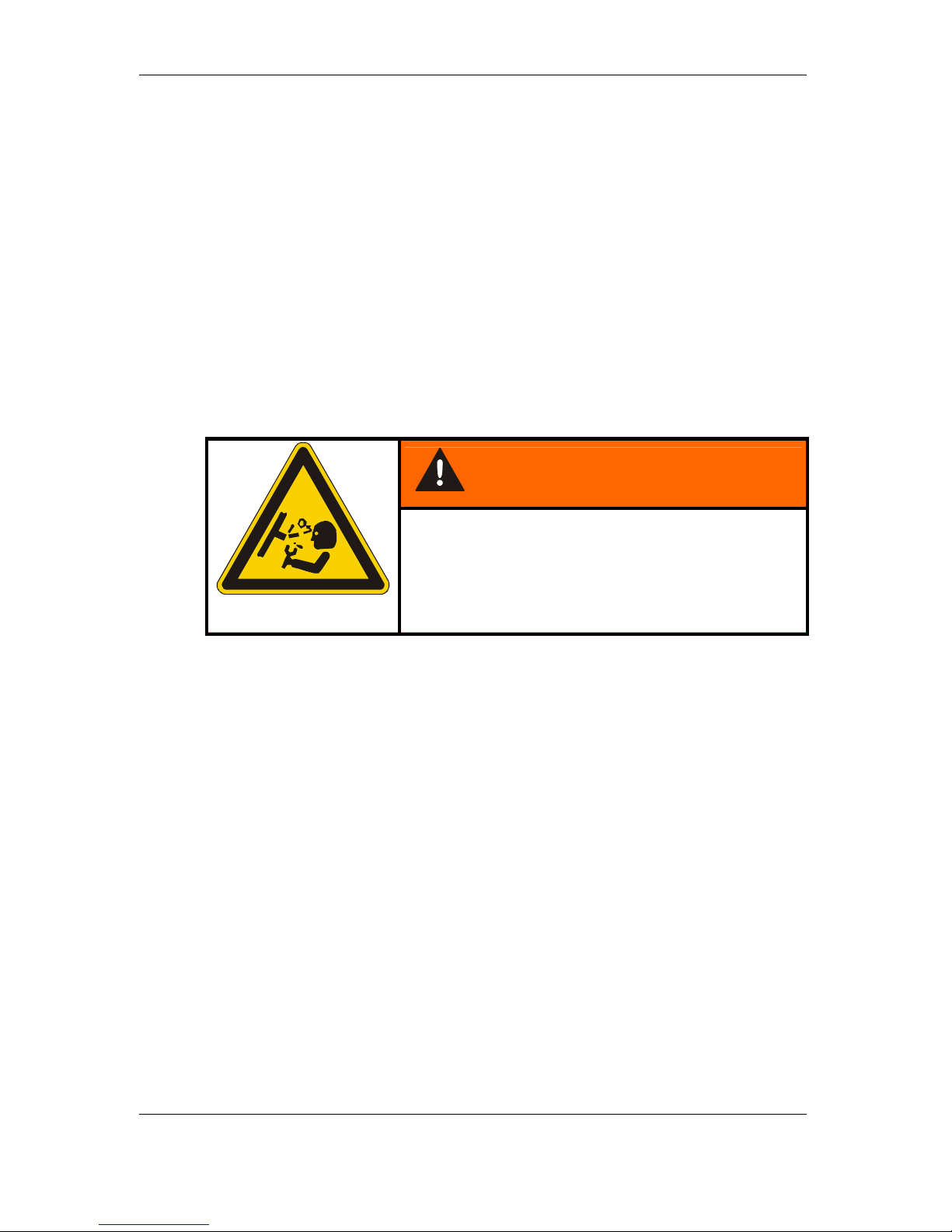
WARNING
Hydraulic systems are under pressure
The hydraulic system must be depressurized
before performing any work

ContaminationSensor – CS 2000 series
HYDAC Filtertechnik GmbH
en
Page 12
BeWa CS2000 3117721e en.doc 2008-03-28
1.6 Training and Instruction of Personnel
The CS may only be operated by properly trained and instructed personnel.
The areas of responsibility of your staff must be established in a clear-cut manner.
Staff undergoing training may not use the CS unless supervised by an experienced
staff member.
Individuals
Activity
Individuals
undergoing
training
Individuals
with
technical
training/
engineering
background
Electrician Supervisor
with the
appropriate
authority
Packing
Transportation
X X
X
Commissioning
X X X
Operation
X X X X
Troubleshooting/
locating the source of
malfunction
X X X
Remedying of
mechanical faults
X
X
Remedying of
electrical faults
X X
Maintenance
X X X X
Repair work
X
Shutdown
Storage
X X X X
1.7 Safety measures to be followed in normal operation
Do not operate the CS unless all the safety devices function properly.
The product must be checked once daily for external damage and the proper
functioning of the safety devices.
1.8 Electrical Hazards
Any work involving the power supply may only be done by a properly trained,
certified electrician.
Make sure to check the electrical equipment of the product on a regular basis. Any
loose connections or damaged cables are to be remedied/replaced immediately.
If work on live components is required, a second individual should be present to
switch off the unit if necessary.

ContaminationSensor – CS 2000 series
HYDAC Filtertechnik GmbH
en
Page 13
BeWa CS2000 3117721e en.doc 2008-03-28
1.9 Maintenance, Servicing and Troubleshooting
The prescribed adjustment, maintenance/servicing and inspection work is to be
conducted in a timely fashion.
All operating media are to be protected/isolated in case the product is accidentally
started up.
The CS is to be disconnected from the power supply and protected against being
inadvertently switched back on when performing any maintenance, servicing,
inspection or repair work.
Check any screwed fittings which have been removed to see that they have been
properly secured.
Always check the product to see that it functions properly when performing
maintenance and servicing work.
1.10 Modifications to the CS
Do not make any modifications (design modifications, extensions) to the CS without
the prior consent of the manufacturer.
Any design modifications or extensions may not be made without HYDAC
Filtertechnik GmbH’s express prior written approval.
Immediately replace any machine components which are not in perfect condition.
Only use original (OEM) spare parts and wearing parts. Non-OEM components have
no guarantee that they have been designed and manufactured so as to comply with
loading and safety requirements.
1.11 Cleaning the CS and Disposal of the Media and Agents Used
The cleaning agents and flushing oils used are to be handled and disposed of
properly.
The manufacturers' instructions relating to possible use, personal protective
equipment and appropriate disposal must be observed.

ContaminationSensor – CS 2000 series
HYDAC Filtertechnik GmbH
en
Page 14
BeWa CS2000 3117721e en.doc 2008-03-28
2 Packing, Transportation, Storage and Disposal
2.1 Transportation Packing
The CS is delivered packed in foils.
When receiving and unpacking the product check it for damage in transit. Report
any damage to the forwarding agent immediately .
The packing material is to be disposed of as specified by law or national regulations
or be reused.
2.2 Storage
Store the CS in a clean, dry place, in the original packing, if possible. Do not remove
the packing until you are ready to install the unit.
Completely drain the CS before it is put into storage for an extended period of time
(flush with n-heptane if necessary) to prevent it from gumming up.
The cleaning agents and flushing oils used are to be handled and disposed of
properly.
2.2.1 Storage conditions
Storage temperature: -20°C ... +85°C / -4°F ... +185°F
Relative humidity: max. 90%, non-condensing
Period of storage max. 6 months
2.3 Disposal / Recycling and Decommissioning
When decommissioning and/or disposing of the CS, observe all local guidelines and
regulations pertaining to occupational safety and environmental protection. This
applies in particular to the oil contained in the unit, to components coated in oil and
to electronic components.
After disassembling the unit and separating the various materials, they can be
reused or are to be disposed of properly in accordance with local regulations.
ContaminationSensor – CS 2000 series
HYDAC Filtertechnik GmbH
en
Page 15
BeWa CS2000 3117721e en.doc 2008-03-28
3 Scope of Delivery
The ContaminationSensor CS is delivered packed and ready to operate. Before
starting up the CS, please check no items are missing from the package.
The following items are supplied:
Item Qty. Description
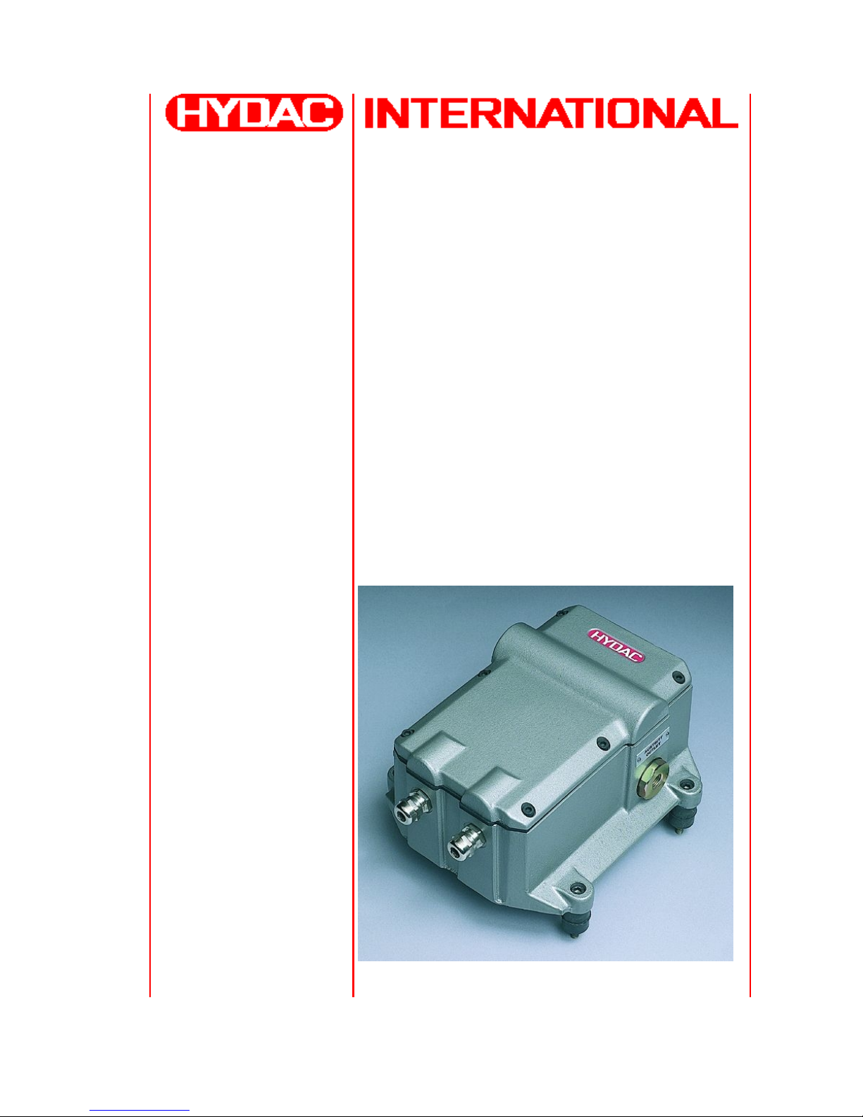
1 1 ContaminationSensor CS2000, ready for connection
- 1 Connection cable CS <-> PC
- 1 Operating and maintenance instructions
1

ContaminationSensor – CS 2000 series
HYDAC Filtertechnik GmbH
en
Page 16
BeWa CS2000 3117721e en.doc 2008-03-28
4 Technical Description of the CS
4.1 General data
The ContaminationSensors of the CS 2000 series are stationary measuring devices
for continuously monitoring solid particle contamination in hydraulic systems.
They have been specifically developed for applications in the test rig area, where it
is necessary to record measurement values in the hydraulic system and display
these values remotely on the control panel, as well as to store the data on a PC.
Device types CS 2030, 2130 and 2230 are designed for applications with mineral
oils and various synthetic hydraulic fluids (e.g. HLP, HLPD), whilst types CS 2031,
2131 and 2231 are only allowed to be operated with certain fluids in the HFD group
(e.g. HFD-R, phosphate tester). If you are unclear about suitability for use with
particular fluids, please contact the sensor manufacturer to inquire about usability.
Because the other device properties are identical, the types CS 203X, 213X and
223X are dealt with below for the sake of simplicity.
Particulate contamination is recorded using a fiber-optic infrared measurement cell
patented by HYDAC and can be output as particle counts or as contamination
classes in accordance with NAS 1638 or ISO 4406:1987 / SAE AS 4059 or ISO
4406:1999.
The particulate contamination is recorded in the following particle size ranges:
CS 203x
Particle count / NAS channels 5..15µm 15..25µm 25..50µm > 50µm
ISO channels > 5µm > 15µm
CS 213x
Particle count / NAS channels 2..5µm 5..15µm 15..25µm > 25µm
ISO channels > 2µm > 5µm > 15µm
CS 223x
Particle count / NAS channels 4..6µm
(c)
6..14µm
(c)
14..21µm
(c)
> 21µm
(c)
ISO channels > 4µm
(c)
> 6µm
(c)
14 µm
(c)
The CS is designed to be connected to low-pressure hydraulic lines from which a
small oil flow portion is branched off for measurement.
By varying the internal orifices, it is possible for the sensors to be configured at the
factory for various operating conditions (pressure/viscosity ranges).
An integrated pressure relief valve protects the ContaminationSensor against
pressures of as much as 350 bar / 5000 psi.
The measured contamination class or the particle counts are continuously output via
various (some optional) electrical outputs (relay, PLC interface, serial display
interface, analog current output 4-20 mA, fieldbus interface) and can thus be
registered and displayed by means of a PLC, an analog voltmeter or a PC.

ContaminationSensor – CS 2000 series
HYDAC Filtertechnik GmbH
en
Page 17
BeWa CS2000 3117721e en.doc 2008-03-28
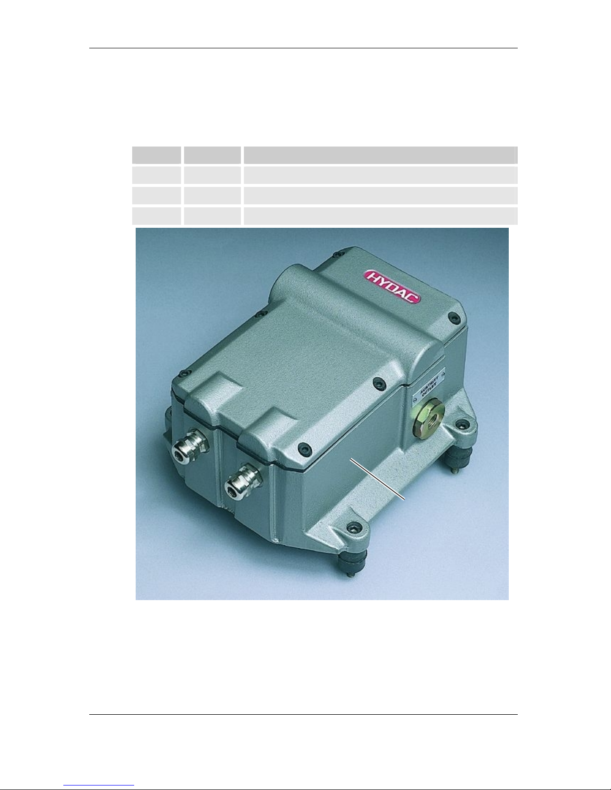
4.2 CS Design
The ContaminationSensor consists of the following components:
• Aluminum housing
• Hydraulic connections "Eingang / Inlet" and "Ausgang / Outlet"
• Fiber-optic infrared measurement cell
• Pressure control valve
• Electronics, consisting of:
Signal processing and microprocessor board
Printed circuit board with connection terminals and internal power supply
unit
Module printed circuit board for optional outputs
Power supply unit for internal supply voltages
Cable glands for the electrical connections
4.3 Restrictions pertaining to use
The CS 2X30 is designated for mineral oils (or mineral-oil-based
raffinates). The CS 2X31 is suitable for phosphate testers.
Please contact us first before using the unit with other fluids.
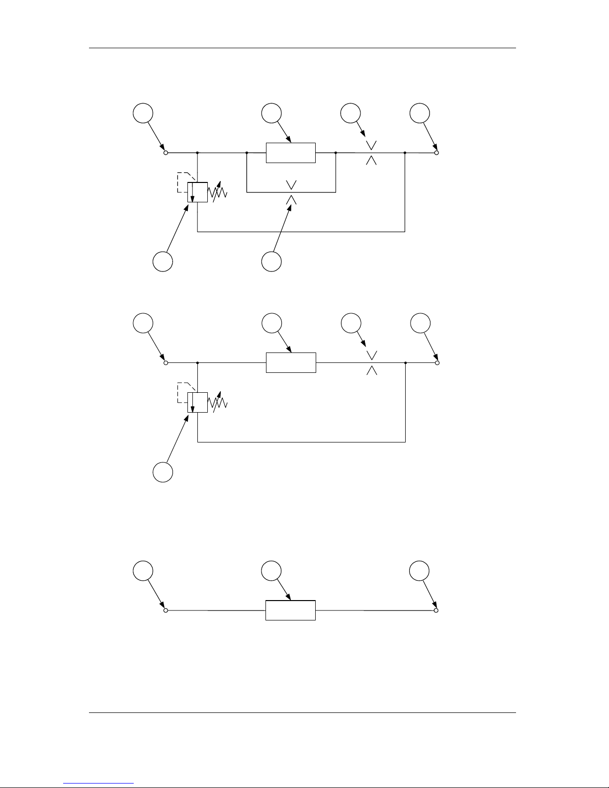
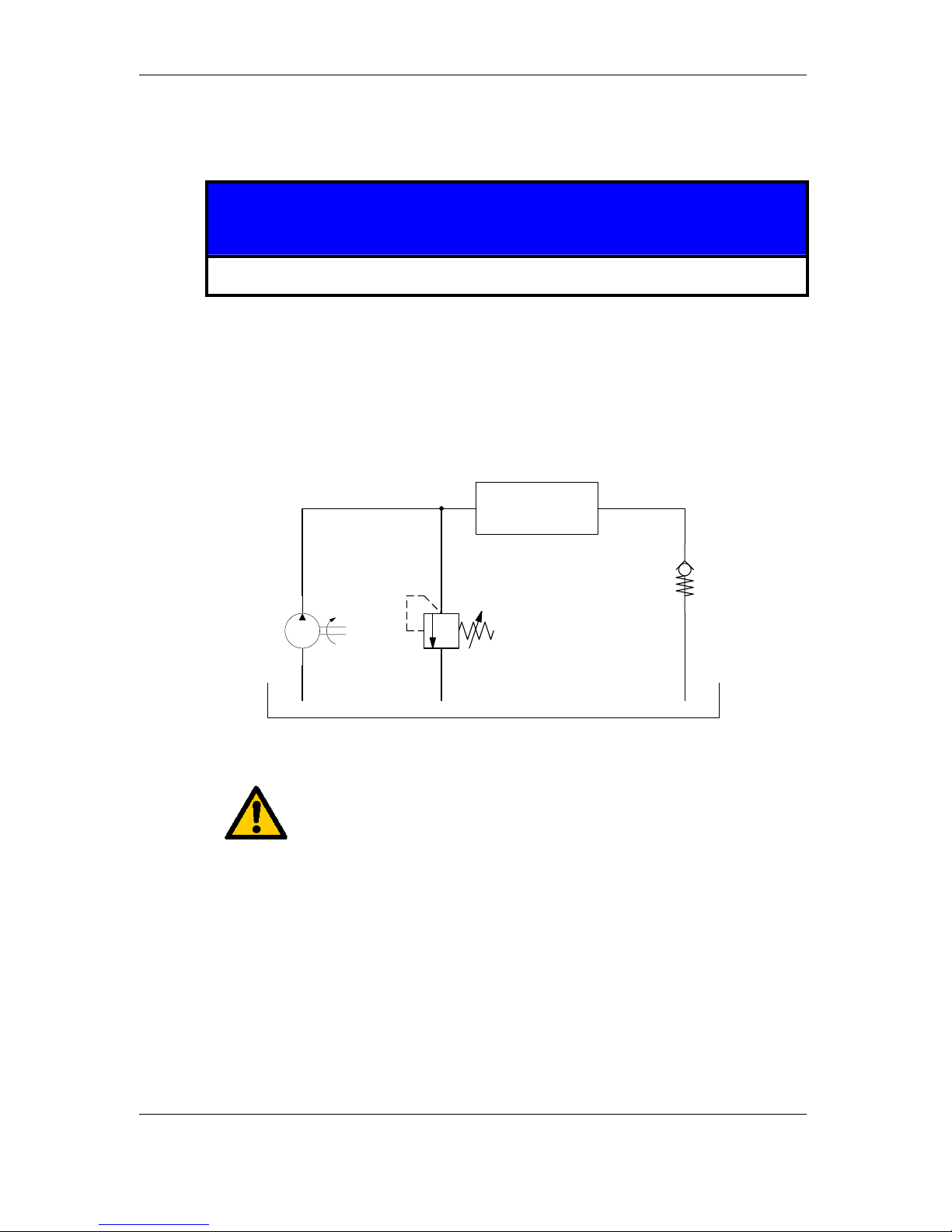
4.4 Hydraulic Schematic
Legend:
Item Description
1 Eingang / Inlet
2 Differential pressure relief valve 40 bar
3 Fiber-optic infrared measurement cell
4 Bypass with orifice
5 Output orifice
6 Ausgang / Outlet
ContaminationSensor – CS 2000 series
HYDAC Filtertechnik GmbH
en
Page 18
BeWa CS2000 3117721e en.doc 2008-03-28
4.4.1 Hydraulic schematic for pressure/viscosity ranges 1 and 2
1
2
1 6
2
3
4
5
4.4.2 Hydraulic schematic for pressure/viscosity ranges 3 and 4
1
2
1 6
2
3 5
4.4.3 Hydraulic schematic for CS 2xxx0
1 63
ContaminationSensor – CS 2000 series
HYDAC Filtertechnik GmbH
en
Page 19
BeWa CS2000 3117721e en.doc 2008-03-28
5 Installation and Operation
5.1 Electrical Installation
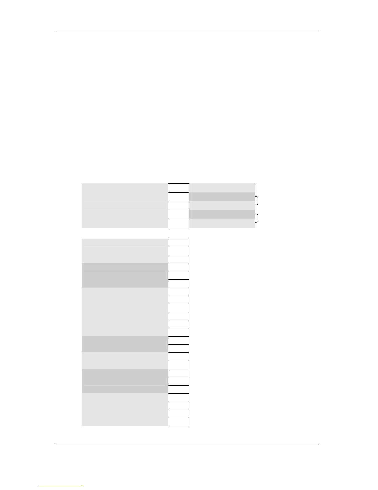
5.1.1 Terminal Assignment
There are two M16x1.5 cable glands through which the electrical power supply and
signal lines can be routed into the housing.
The housing of the ContaminationSensor contains the identification of the terminal
assignment that specifies the particular configuration.
The terminals used feature spring-cage technology and are suitable for the following
conductor cross sections:
Terminals for supply voltage up to 2.5 mm²
Terminals 1 – 23 up to 0.5 mm²
Power Terminal
PE
Case Ground
0 V Supply Voltage 0 V
0 V Supply Voltage 0 V
24 V Supply Voltage 24 V
Supply voltage
24 V Supply Voltage 24 V
Declaration:
1. Pair of clamps is for
Supply Voltage.
2. Pair of clamps is for
additional connection from
a load (CSD for Example).
Signal Terminal
1 PLC Ground
2 24 V from PLC
Digital Output for PLC
3 PNP Output to PLC
4 RS 232 Ground
5 RS 232 TxD
Serial RS 232 Display port
6 RS 232 RxD
7
8
9
10
11
Module port:
12
Assignment dependent upon output modul
13 Relay 1, NO
Relay 1
14 Relay 1, C
15 Relay 2, NO
Relay 2
16 Relay 2, C
17 Ready Relay, NC
18 Ready Relay, NO
Ready relay
19 Ready Relay, C
20 Analog Supply +12 V
21 Analog Signal Channel 1
22 Analog Ground
Analog Input
23 Analog Signal Channel 2

ContaminationSensor – CS 2000 series
HYDAC Filtertechnik GmbH
en
Page 20
BeWa CS2000 3117721e en.doc 2008-03-28
The terminal assignment of the module port varies according to the various optional
output modules.
The terminal assignments of the individual modules are shown below:
RS 232 Modul (Option –0)
You will find the description for this module in Chapter
11.
7 Free
8 Free
9 Ground
10 Free
11 TxD
RS 232
12 RxD
Analog module (Option –1)
You will find the description for this module in Chapter
13.
7 4 - 20 mA (+)
8 Free
9 Free
10 Free
11 Free
Analog
12 4 - 20 mA (-)
DIN measurement bus module (option –2)
You will find the description for this module in Chapter
10.
7 RB (+)
8BUS 5 V
9 BUS Ground
10 TB (+)
11 TA (-)
DIN Measurement Bus
12 RA (-)
Ethernet module (Option –5)
You will find the description for this module in Chapter
12.
7RxD+
8RxD-
9TxD+
10 TxD11 Free
Ethernet
12 Free

ContaminationSensor – CS 2000 series
HYDAC Filtertechnik GmbH
en
Page 21
BeWa CS2000 3117721e en.doc 2008-03-28
RS 232 / analog module (option –6)
This module represents a combination of the variants RS 232 (Option –0) and
Analog (Option –1). A description of the funcationalities can be found in Chapter
11
and Chapter
12.
7 4 - 20 mA (+)
8 4 - 20 mA (-)
9 Ground
10 Free
11 TxD
RS232 / analog
12 RxD
RS 485 / analog module (option –7)
This module represents a combination of the variants DIN Measurement Bus
Module (Option –2) and Analog (Option –1). A description of the funcationalities can
be found in Chapters
10 and 13.
7 RA (-)
8 4 - 20 mA (-)
9 4 - 20 mA (+)
10 TA (-)
11 TB (+)
RS485 / analog
12 RB (+)
ContaminationSensor – CS 2000 series
HYDAC Filtertechnik GmbH
en
Page 22
BeWa CS2000 3117721e en.doc 2008-03-28
5.2 Electrical connection of the CS
Before continuing, check whether the CS is suitable for your display/data capturing
system by carefully examining the technical specifications.
First connect the signal lines (pins/terminals 1 to 23).
Then connect the supply voltage.
CS starts measurement operation as soon as the supply voltage is applied.
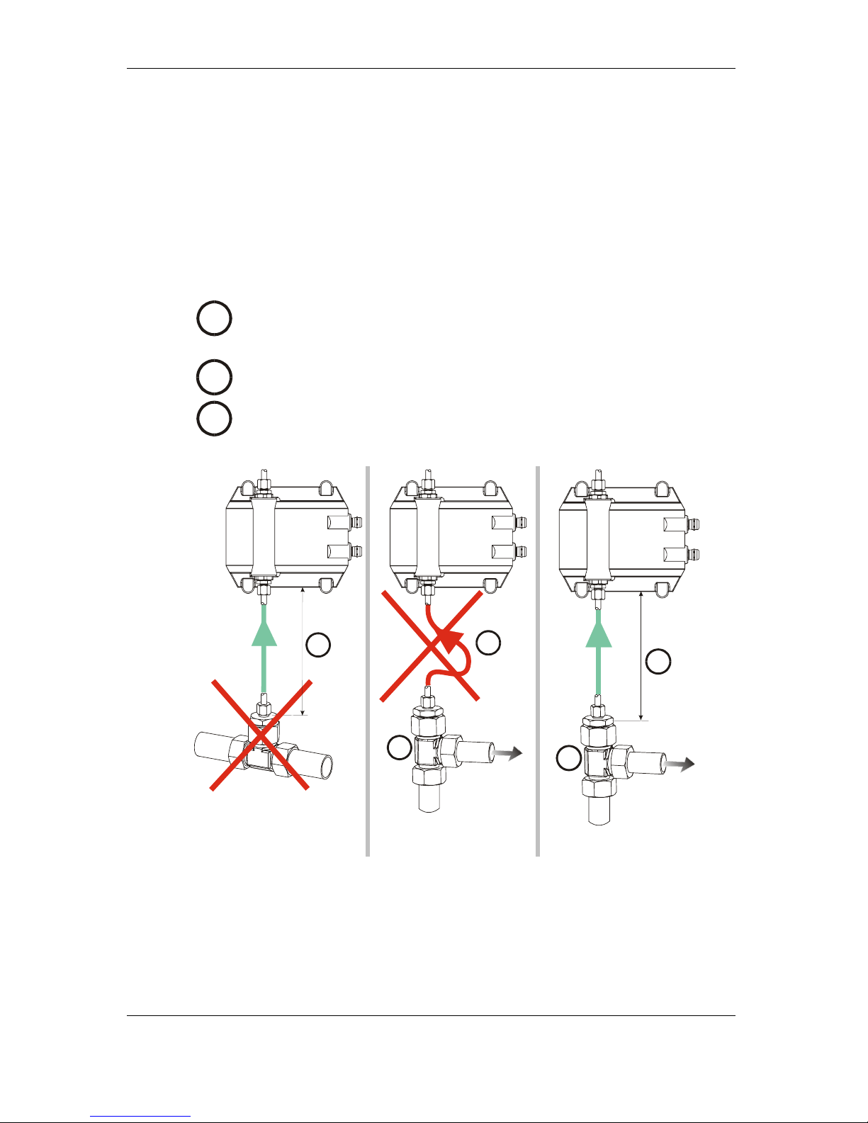
5.3 Selecting a measurement point
1
The measurement point should be selected so that the measured volume
comes from a turbulent area with a good through-flow. For example: on a
pipe elbow, etc.
2
The CS has to be installed in the vicinity of the measurement point in order
to obtain precision-timed results.
3
While installing the measurement line, avoid creating a "siphon" trap for
sedimentation (particle deposits in the line).
A
B
2
A
B
1
3
A
B
2
1
WRONG WRONG OK
ContaminationSensor – CS 2000 series
HYDAC Filtertechnik GmbH
en
Page 23
BeWa CS2000 3117721e en.doc 2008-03-28
5.4 Hydraulic connection of the CS
Determine the system pressure of the hydraulic facility and see whether it is within
the permissible range for the INLET port.
TIP
The pressure in the measurement cell is not allowed to exceed 40 bar!
The built-in pressure relief valve does not open until there is a pressure differential
of 40 bar between the INLET and OUTLET.
If pressure values greater than 40 bar occur on the INLET connection and the
OUTLET connection is not depressurized at the same time, the CS must be
protected by an additional pressure relief valve (e.g.: ConditioningModule Inlet, CMI).
1
2
1
2
CS
max. 40 bar
Example for protecting the CS if OUTLET is not depressurized
Warning: Oil starts to flow through the CS as soon as the
system has been connected to the pressure fitting.
This is why it is vital that connection be done in the
sequence specified above.
The return-line connector (OUTLET) must never be
obstructed or closed off!
1. Connect the CS hydraulically to your system as follows:
2. First connect the return-flow line (not supplied) to the OUTLET port of the
CS.
(Connector thread: G1/4, ISO 228. Recommended internal diameter of
conduit: >4 mm)
3. Now connect the other end of the return-flow line, e.g. to the system tank.
4. Check the pressure at the measurement point; it has to be within the
specified limits.

ContaminationSensor – CS 2000 series
HYDAC Filtertechnik GmbH
en
Page 24
BeWa CS2000 3117721e en.doc 2008-03-28
5. First connect the measurement line (not supplied) to the INLET port of the
CS.
(Connector thread: G1/4, ISO 228. Recommended internal diameter of
conduit (to prevent particle sedimentation): ≤ 4 mm)
6. Now connect the other end of the measurement line to the measurement
point.
7. Installation of the CS is now complete and it now continuously outputs the
measured values via the electrical interface(s).
5.5 Removing the CS from the Hydraulic System
1. Disconnect the CS from the voltage supply.
2. Disconnect the other electrical connectors.
3. Remove the measurement hose from the hydraulic system first, then from
the INLET port of the CS.
4. Remove the return-flow line from the OUTLET port of the CS .
The CS can now be removed.

ContaminationSensor – CS 2000 series
HYDAC Filtertechnik GmbH
en
Page 25
BeWa CS2000 3117721e en.doc 2008-03-28
6 Description of the Measuring Modes
6.1 Mode M1: Measure
Continuous measurement without special switching functions.
The current measurement result is output via the available interfaces after the
measurement interval has elapsed.
6.2 Mode M2: Measure and switch
Continuous measurement, with relays 1 and 2 being switched according to the set
measuring channels, switching functions and limit values.
The current measurement result is output via the available interfaces after the
measurement interval has elapsed.
6.3 Mode M3: Filter until
Measuring mode in which relay 1 is closed, until 5 successive measurements reach
or are cleaner than the set target cleanliness value. Measurement in mode 3 is then
stopped.
Once relay 1 has been opened, it remains open until a measurement is restarted. (A
restart can be triggered using the DIN measurement bus interface, the RS 232
display interface or by switching the electrical power supply off/on.)
6.4 Mode M4: Filter from until
Measuring mode in which relay 1 is closed, until 5 successive measurements reach
or are cleaner than the set target cleanliness value (lower limit).
The relay is then opened and the test cycle time is started. After the test cycle time
has elapsed, relay 1 is closed and a measurement is performed.
If the upper cleanliness value (upper limit) is reached or not exceeded, relay 1
remains closed until 5 successive measurements once again reach or are cleaner
than the set target cleanliness value.
If the upper cleanliness value (upper limit) is not reached or was exceeded, relay 1
is opened again and the test cycle time is restarted.
6.5 Switching behavior of the relays:
The following table describes the switching behavior of the three relays in the
various measuring modes.
The position of the relays is updated after a measurement interval has elapsed, by
comparing the current measured values with the limit values.
Directly after the CS is switched on, the Common (C) and Normally Closed (NC)
contacts of all relays are connected together. As soon as the operational readiness
of the CS has been established, the C and NO contacts are connected together on
the Ready relay.

ContaminationSensor – CS 2000 series
HYDAC Filtertechnik GmbH
en
Page 26
BeWa CS2000 3117721e en.doc 2008-03-28
Relays 1 and 2 are not switched until after the first measurement interval has
expired.
Ready relay
on
NC
NO
C
Ready relay
off
NC
NO
C
Relay 1
on
NO
C
Relay 1
off
NO
C
Relay 2
on
NO
C
Relay 2
off
N
O
C
M1
CS ready for
operation
CS not ready
for operation
Measurement
currently in
progress
Measurement
stopped
After first
value is
present: Flow
error
Flow in
nominal
range
M2 (measuring channels 1 / 2 / 3 / 4 / 5 / 6 / 9 / 10)
Exceed
CS ready for
operation
CS not ready
for operation
≥ upper limit
After switchon or start of
a
measurement
.
Off again if ≤
lower limit
≥ upper limit
After switchon or start of
a
measureme
nt.
Off again if ≤
lower limit
Fall below
CS ready for
operation
CS not ready
for operation
≤ lower limit
After switchon or start of
a
measurement
.
Off again if ≥
upper limit
≤ lower limit
After switchon or start of
a
measureme
nt.
Off again if ≥
upper limit
Within range
CS ready for
operation
CS not ready
for operation
Lower limit ≤
value ≤ upper
limit
After switchon or start of
a
measurement
.
Off again if
value < lower
limit or
Measured
value > upper
limit
Lower limit ≤
value ≤ upper
limit
After switchon or start of
a
measureme
nt.
Off again if
value <
lower limit or
Measured
value >
upper limit
Outside
range
CS ready for
operation
CS not ready
for operation
Value ≤ lower
limit or
Value ≥ upper
limit
After switchon or start of
a
measurement
.
Off again if
lower limit <
value < upper
limit
Measured
value ≤ lower
limit or
Value ≥ upper
limit
After switchon or start of
a
measureme
nt.
Off again if
lower limit <
value <
upper limit
No function
CS ready for
operation
CS not ready
for operation
Always off Always off
M2 (measuring channels 7 and 8)
Exceed
CS ready for
operation
CS not ready
for operation
A value ≥
After switchon or start of
A value ≥
After switchon or start of
 Loading...