

Hydac CS 1x10-B-0-0-0-1/-000, CS 1x11-A-0-0-0-0/-000, CS 1x10-B-0-0-0-0/-000, CS 1x10-A-0-0-0-0/-000, CS 1x11-A-0-0-0-1/-000 Quick Start Manual
...Page 1
Kurzanleitung
CS 1000 Serie
Quick start manual CS 1000 series
Notice série
CS 1000 condensée
Seriennummer
/ Serial
number
/ Numéro
de série:
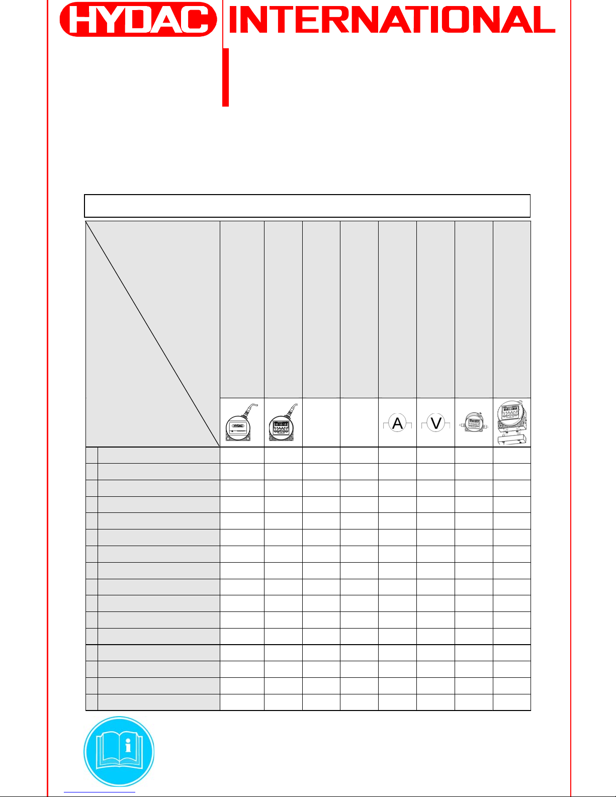
1) Identifikation
1) Identification
1) Identification
Bitte ergänzen Sie im folgenden die Seriennummer Ihres CS 1000 und markieren Sie seinen Typenschlüssel /
Please
add
below
the
serial
number
of your
CS 1000 and mark
its
model
code
/
Veuillez
ajouter
suivant
le numéro
de série
de votre
CS 1000 et marquer
son
code
de commande:
Bitte beachten Sie die Betriebs-
und Wartungsanleitung!
Please
note
the
operating
and maintenance
instructions!
Veuillez
prendre
en compte
le manuel
d‘utilisation
et d‘entretien!
ohne Display /
without display /
sans écran
mit Display /
with display /
avec écran
für Fluide auf Mineralölbasis /
for fluids based on mineral oil/
pour fluides à base d´huile minérale
für Phosphatester /
for phosphate esters /
pour esters phosphates
4 ... 20 mA Analogausgang /
Analog output /
Sortie analogique
0 ... 10 V Analogausgang /
Analog output /
Sortie analogique
Rohrleitungs- oder Schlauchanschluss /
Pipe or hose connection /
Raccord de la tuyauterie ou du flexible
Flanschanschluss /
Flange connection /
Raccordement par bride
Merkmale /
Characters/
Caractéristiques
TypenSchlüssel /
Model code /
Code de
commande
FPM EPDM
CS 1 x 1 0
-A-0-0-0-0/-000
CS 1 x 1 0
-A-0-0-0-1/-000
CS 1 x 1 0
-B-0-0-0-0/-000
CS 1 x 1 0
-B-0-0-0-1/-000
CS 1 x 1 1
-A-0-0-0-0/-000
CS 1 x 1 1
-A-0-0-0-1/-000
CS 1 x 1 1
-B-0-0-0-0/-000
CS 1 x 1 1
-B-0-0-0-1/-000
CS 1 x 2 0
-A-0-0-0-0/-000
CS 1 x 2 0
-A-0-0-0-1/-000
CS 1 x 2 0
-B-0-0-0-0/-000
CS 1 x 2 0
-B-0-0-0-1/-000
CS 1 x 2 1
-A-0-0-0-0/-000
CS 1 x 2 1
-A-0-0-0-1/-000
CS 1 x 2 1
-B-0-0-0-0/-000
CS 1 x 2 1
-B-0-0-0-1/-000
Page 2
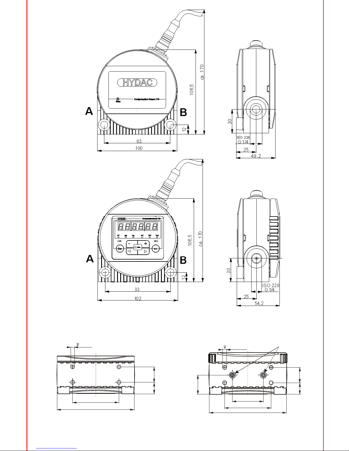
2) Abmessungen
2) Dimensions
2) Dimensions
CS 1x1x ohne
Display
CS 1x1x without display
CS 1x1x sans écran
CS 1x2x mit Display
CS 1x2x with display
CS 1x2x avec écran
Unterseitenansicht
Bottom
view
Vue
de dessous
für Flanschanschluss-Version
for
flange
connection
pour raccordement
par bride
für Rohrleitungs-
oder Schlauchanschluss
for
pipeorhose
connection
pour raccord
de la tuyauterieoudu flexible
CD
25
15 20
100
40
60
12/16
4xM6
[2]
A
B
100
60
12/16
4xM
6
15
20
[2] –
O-Ring
/ o-ring / joint
torique
Page 3
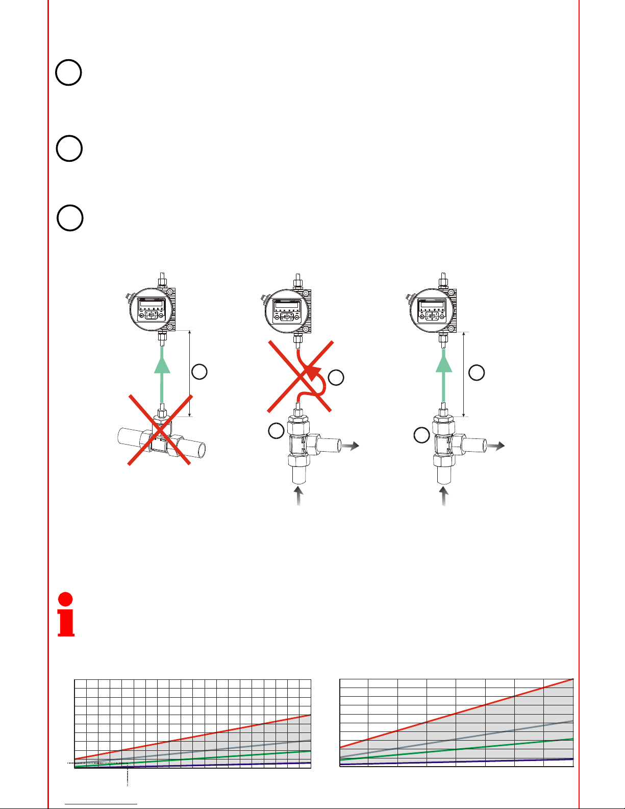
Der
Messpunkt
soll
so gewählt
werden, dass
das Messvolumen
aus
einer
turbulenten
gut durchströmten
Umgebung
stammt. Zum
Beispiel: an einem
Rohrbogen, etc..
The measurement point has to be selected so that the measured volume is taken from a turbulent flow area, i.e. a
pipe bend.
Le point de mesure
doit
être
choisi
de sorte
que
le volume de mesure
provienne
d’un environnement
présentant
un
bon écoulement
de type turbulent, par exemple
au niveau
d’un coude, etc.
Damit
möglichst
zeitgenaue
Ergebnisse
erreicht
werden, muss der
CS in der
Nähe
des Messpunktes
installiert
werden.
The CS has to be installed in the vicinity of the measurement point in order to obtain precision-timed results.
Afin
d’obtenir
des résultats
aussi
précis que
possible sous
l’angle
du temps, le CS doit
être
installéàproximité
du
point de mesure.
Um Sedimentation (Ablagerungen
von Partikeln
in der
Leitung) zu
vermeiden, ist
bei
der
Installation der
Messleitung
ist
daraufzuachten, dass
kein
"Siphon" eingebaut
wird.
While installing the measurement line, make sure that no "siphon
trap" is created so as to prevent sedimentation
buildup (formation of particle deposits in the line).
Afin
d’éviter
tout risque
de sédimentation
(dépôt
de particules
dans
la conduite), veilleràce
que
le trajet
de la
conduite
de mesure
ne présente
pas de “siphon”.
A
B
2
A
B
1
3
A
2
1
B
4) Durchfluss, Differenzdruck und Viskosität Charakteristik
4) Flow Rate, Differential Pressure and Viscosity Characteristics
4) Caractéristiques
de débit, de pression
différentielle
et de viscosité
3) Richtlinien zur Auswahl einer Messstelle
3) Selection Guidelines for a Measurement Point
3)
Directives
pour le choix
d‘un
point de mesure
Der
zulässige
Messvolumenstrom
für
den CS muss zwischen
30 ml/min und 300 ml/min liegen. Sollten Sie
diese Durchflusswerte nicht erreichen, haben wir in unserem umfangreichen Zubehörprogramm
verschiedene Conditioning
Module.
The flow rate range permitted for a measurement must be between 30 ml and a maximum of 300 ml. In the event
you are unable to achieve these flow values, there are various conditioning modules available from our extensive line
of accessories.
Le débit
de mesure
admissible doit
être
compris
entre 30 ml/min et 300 ml/min. S’il
n’est
pas possible d’atteindre
ces
valeurs
de débit, nous proposons
différents
modules de conditionnement
dans
notre
vaste
programme
d’accessoires.
1
2
3
20
Q
m
i
n
=
3
0
m
l
/
m
i
n
1
0
0
m
l
/
m
i
n
1
6
0
m
l
/
mi
n
Q
m
a
x
=
3
00
m
l
/
m
i
n
0
1
0
2
0
3
0
4
0
5
0
6
0
7
0
8
0
9
0
1
0
0
1
1
0
1
2
0
1
3
0
1
4
0
1
5
0
1
6
0
1
7
0
1
8
0
1
9
0
2
0
0
18
16
14
12
10
8
6
4
2
0
p
[
b
ar]
D
[mm /s]
v
2
1 bar
46 mm /s
2
50
Q
mi
n
=
3
0
ml
/
mi
n
1
0
0
m
l
/
m
i
n
Q
m
a
x
=
3
0
0
ml
/
m
i
n
200
3
0
0
40
0
5
0
0
60
0
7
0
0
8
0
0
90
0
10
0
0
45
40
35
30
25
20
15
10
5
0
1
6
0
m
l
/
m
i
n
p
[bar]
D
[mm /s]
v
2
Page 4
[1] [2]
[1]
C
A
B
D
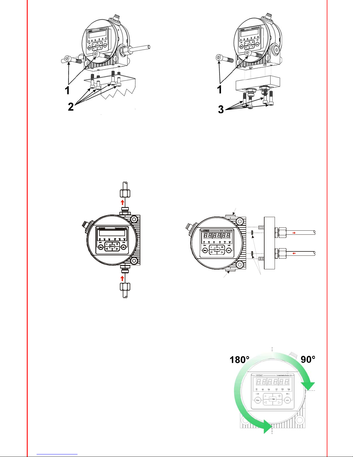
5) Montage
5) Mounting
5) Montage
6) Hydraulischer
Anschluss
6) Hydraulic connection
6) Raccordement
hydraulique
für Flanschanschluss-Version
for
flange
connection
pour raccordement
par bride
für Rohrleitungs-
oder Schlauchanschluss
for
pipeorhose
connection
pour raccord
de la tuyauterieoudu flexible
1 : mit 2 x M8 (ISO 4762) / with
2 x M8 (ISO 4762) / avec
2 x M8 (ISO 4762) oder / or
/ ou
2, 3 : mit 4 x M6 / with
4 x M6 / avec
4 x M6
oder / or
/ ou
Rohrleitungs-
und Schlauchanschluss
mit Gewinde
G1/4, ISO 228
Pipe or hose connection with thread G1/4, ISO 228
Raccord
de la tuyauterieoudu flexible avec
filetage
G1/4, ISO 228
Flanschanschluss mit DN4
Flange connection with DN4
Raccordement
par bride
avec
DN4
A
B
Das Display des CS 1000 kann von Hand gegen den Uhrzeigersinn
um 180°
und um 90°
im Uhrzeigersinn gedreht werden.
The display of the CS 1000 can be rotated through 180°
in a
counterclockwise direction and through 90°
in a clockwise direction by
hand.
L´écran du CS 1000 peut être tourné
de 180°
dans le sens anti-horaire
et de 90°
dans le sens horaire.
[1] –
Verschlussschraube
/ Srew
plug
/ Bouchond‘etanchéité
[2] –
O-Ring
/ o-ring / joint
torique
Page 5

Um Messfehler durch im System befindliche und eingeschlossene Luft zu vermeiden, empfehlen wir eine
Durchflussrichtung von unten nach oben (senkrecht) durch den CS,
Verwenden Sie einen Anschluss A<->B
oder D<->C als Eintritt (INLET) und den anderen als Austritt (OUTLET).
Verbinden des CS mit Ihrem System nach folgenden Schritten:
1.
Verbinden Sie als erstes die Rücklaufleitung mit dem Austritt (OUTLET) des CS.
Anschlussgewinde G1/4 ISO 228, empfohlener Innendurchmesser der Leitung
4mm.
2.
Verbinden Sie nun das andere Ende der Rücklaufleitung z.B. mit dem Systemtank.
3.
Prüfen Sie den Druck an der Messstelle. Dieser muss sich innerhalb der zulässigen Bereiche befinden. Der
max. Betriebsdruck darf nicht überschritten werden.
4.
Verbinden Sie nun die Messleitung mit dem Eintritt (INLET) des CS.
Anschlussgewinde G1/4 ISO 228, empfohlener Innendurchmesser der Leitung
4mm (um einer
Partikelablagerung vorzubeugen).
Sind im Hydrauliksystem Partikel größer 400 µm vorhanden bzw. zu erwarten, muss dem CS1000
ein Schmutzsieb vorgeschaltet werden. (z.B. CM-S)
5.
Verbinden Sie nun das andere Ende der Messleitung mit dem Messanschluss.
Öl beginnt durch den Sensor zu fließen, sobald dieser mit der Druckleitung verbunden ist.
Deshalb ist es notwendig, die Verbindung in der zuvor definierten Reihenfolge durchzuführen.
6.
Die hydraulische Installation des CS ist nun komplett.
We recommend that the direction of flow through the CS be from bottom to top (in a vertical direction) in order to prevent
measurement errors caused by air trapped in the system.
Use
one
connection
port
A<->B or
D<->C as the
INLET port
and the
other
as OUTLET port.
Connect the CS to your system as follows:
1.
First connect the return-flow line (not supplied) to the OUTLET port of the CS.
Thread: G1/4 ISO 228, recommended internal diameter of line
4mm
2.
Now connect the other end of the return-flow to the system tank, for example.
3.
Check the pressure at the measurement point; it has to be within
the specified limits. The pressure in the
measurement cell may not exceed max. operating pressure.
4.
Now connect the measurement line (not supplied) to the INLET port of the CS.
Thread: G1/4 ISO 228, recommended internal diameter of line (to prevent particle sedimentation)
4mm
If there are particles larger than 400 microns in the hydraulic system, or this is to be expected,
a strainer has to be installed upstream of the CS1000.
5.
Now connect the other end of the measurement line to the measurement point.
Oil starts to flow through the CS as soon as it has been connected to the pressure fitting.
This is why it is necessary that connection be done in the sequence specified above.
6.
The hydraulic installation of the CS is now complete.
Nous recommandons un sens d'écoulement du bas vers le haut (vertical) à
travers le CS afin d’éviter des erreurs de
mesure par suite de la présence d'air inclus dans le système.
Veuillez
utiliserunorifice
A<->B ou
D<->C comme entrée
(INLET) et l'autre
comme sortie
(OUTLET).
Raccorder le CS à
son système en respectant les étapes suivantes:
1.
Raccordez en premier lieu la ligne retour à
la sortie (OUTLET) du CS.
Raccordement G1/4 ISO 228, diamètre interne recommandé
de la conduite
4mm.
2.
Raccordez ensuite l´autre extrémité
du flexible retour par exemple au réservoir système.
3.
Vérifiez la pression au point de mesure. Celle-ci doit osciller dans la plage autorisée. La pression maxi ne doit pas
être dépassé.
4.
Raccordez maintenant la ligne de mesure avec l´entrée (INLET) du CS.
Raccordement: G1/4 ISO 228, diamètre interne recommandé
de la conduite
4mm (pour éviter la sédimentation
des particules).
Si des particules > 400 µm devaient être présentes ou générées par le système, prévoir une
crépine enamont
du CS (par ex. CM-S).
5.
Raccordez maintenant l´autre extrémité
du flexible au point de mesure.
L´huile balaye la cellule de mesure dès que celle-ci est raccordée au circuit pression.C´est pour cette
raison qu´il faut respecter les différentes étapes décrites ci-avant.
6.
L´installation hydraulique du CS est maintenant complète.
Wichtige Informationen zum ContaminationSensor 1000
Important
information
to the
ContaminationSensor 1000
Informations
importantesàpropos
du ContaminationSensor 1000
Dem CS muss ein erforderlicher Messvolumenstrom von 30 …
300 ml/min zur Verfügung stehen.
Zum Bereitstellen der optimalen Betriebsbedingungen wie Druck, Volumenstrom, etc., haben wir
verschiedene Conditionier
Module im Produktprogramm.
The CS requires a delivery flow rate of 30 …
300 ml/min. The HYDAC product range includes a number of
conditioning modules for creating optimal operating conditions, e.g. pressure, flow rate, etc.
Le CS doit disposer d’un débit compris entre 30 …
300 ml/min.
Afin d’établir des conditions de service optimales en termes de pression, de débit, etc., nous proposons différents
modules de conditionnement dans notre programme de produits.
Page 6

7) Elektrischer
Anschluss
7) Electrical connection
7) Raccordement
électrique
Verkabelungsschema
General wiring
layout
Plan général
d'interconnexions
Schaltbild mit zwei Netzteilen (z.B. 5 VDC)
With
two
power supplies
(e.g. 5 VDC)
Schéma
de raccordement
avec
deux réseaux
(par ex. 5 VDC)
8) Einschalten
8) Switch-on
8) Enclenchement
-
Zunächst die Hydraulikversorgung anschließen.
-
Danach die Spannungsversorgung anschließen.
-
Nach Ablauf der Messzeit (einzustellen im Power Up Menü
/ Werkseinstellung: 60 s) erscheint auf dem
Display ein Messwert. Das Gerät ist jetzt betriebsbereit.
(Wird statt eines Messwertes ein Fehlerstatus angezeigt, so muss der angezeigte
Fehler behoben werden vgl. Kapitel „Fehlermeldungen“
der Betriebs-
und Wartungsanleitung).
-
First connect
the
hydraulic
supply.
-
Then
connect
the
power supply.
-
After the
measuring
time has elapsed
(to be
set
in the
power up menu
/ default: 60 s), there´s
a
measured
value
shown
on the
display. Now, the
unitisready
for
use.
(If
there´s
an error
message
on the
display, the
indicated
error
has to be
corrected
cf. chapter
„Error codes“
of the
operating
and maintenance
instructions).
-
Effectuez
tout d´abord
le raccordement
hydraulique.
-
Effectuez
ensuite
le raccordement
électrique.
-
Après
écoulement
du temps
de mesure
(règlable
dans
le menu
Power-Up
/ par défaut
: 60 s) une
valeur
de mesure
apparaîtàl´écran. L´appareil
est
maintenant
disponible.
(Si au lieu
d´une
valeur
de mesure
apparaîtunstatut
d´erreur, il faut acquitter
préalablement
cette
erreur
confer
chapitre
„Messages
d´erreur“
de la notice
d'utilisation
et de maintenance).
Spannungsversorgung 9 ... 36 V DC /
Supply voltage 9 ... 36 V DC / Alimentation 9 ... 36 V DC
GND für Spannungsversorgung /
GND for supply voltage / GND pour alimentation tension
RS485 +
RS485 -
HSI (HYDAC Sensor Interface)
Analogausgang + / Analog out + / Sortie analogique +
GND für Analog- und Schaltausgang /
GND for analog out and Switch out / GND pour sortie analogique et de commutation
Schaltausgang (passiv, Öffner)
Switch out (passive, n.c.) / sortie commutation ( passive, ouvrant)
Nicht angeschlossen
Not to be connected
Ne conn exe pas
RS-485 +
RS-485 -
250
1
2
3
4
5
6
7
8
Shield
24 V DC
5 V DC
SPS Eingang
PLC Input
SPS Entrée
white
green
pink
blue
grey
brown
yellow
red
USB
RS-485
Converter
=
=
1
7
6
5
4
3
2
Schirm
Shield
Blindage
8
2
3
4
5
6
7
1
Ca s e
M12x1, 8-pol., male,
speci fied acc. IEC61984 / VDE0 627
8
1
2
3
4
5
6
7
8
Vo lt a ge
Reg ul at or
Internal
supply
vol ta ges
galvanically
isolated
sup ply
galvanic
isolat ion
Not to be
conne cte d
1 µF
+
-
DC
DC
Page 7

B
C
D
A
E
Pos. Bezeichnung /
Description /
Description
A
Statusanzeige des ContaminationSensor
Indicates the status of the ContaminationSensor
Indication du statut du ContaminationSensor
B
6-stellige Messwertanzeige
Six digit measured value display
Affichage de la valeur de mesure à 6 positions
C
Anzeige der jeweiligen Messgröße oder Servicegröße welche im Display dargestellt wird.
Indicates the measured or service variable of the display value, i.e.
Affichage de chaque variable de mesure ou variable de service qui est affichable à l´écran.
ISO / SAE / Flow / Out / Drive / Temp
D
Statusanzeige Schaltausgang. Leuchet die LED ist der Schaltausgang aktiviert, d.h. geschlossen.
Indicates the status of the switching output. When lit, the switching output is activated (closed).
Indication du statut de la sortie de commutation. LED allumé, sortie activée et contact fermé.
E
Reserviert für zukünftigen Gebrauch.
Reserved for future use.
Réservé pour des applications futures.
9) Display + Tastatur
9) Display + Keypad
9) Ecran
+ clavier
Taste /
Key /
Bouton
Beschreibung /
Desription /
Descrition
o.k.
- eine Ebene tiefer
/ one level down
/
un niveau plus bas
- Bestätigen eines geänderten Wertes (unterste Ebene)
/
confirm changed value (lowest level) /
Confirmer une valeur modifiée (niveau inférieur)
- Bestätigen, um Änderungen zu speichern oder zu verwerfen (oberste Ebene)
/
confirm when changes are to be saved or cancelled (top level) /
Confirmer pour enregistrer ou rejeter des modifications (niveau supérieur)
Esc
- eine Ebene höher
/ one level up
/ un niveau plus haut
- keine Werte ändern
/ no value change /
ne pas modifier de valeurs
+
- Werte ändern auf der untersten Ebene (Ist die unterste Ebene erreicht, blinkt das Display)
/
change value at the lowest level (when display is blinking) /
Modifier des valeurs au niveau inférieur (lorsque le niveau inférieur est atteint, l’écran clignote
- über das Display blättern
/ scroll through display / -
feuillers sur l’écran
- durch das Menü blättern
/ scroll through menu /
feuilleter dans le menu
- Zahlen auswählen
/ select digit /
choisir des chiffres
Die Tastatur
besteht
aus
sechs
Tasten. Mit
diesen
Tasten
kann
der
CS bedient
und durch
die hierarchisch
strukturierten
Menüs
bewegt
werden.
The keypad consists of six keys. These keys are used to operate the CS and to navigate through the menus
(hierarchically structured).
Le clavier comporte
six touches qui permettent
de piloter
le CD et de naviguer
au sein
des menus à
structure
hiérarchique.
Page 8

10) CS 12xx
Menüstruktur
/ Menu
structure
/ Structure
de menus
owerUp Menu
MODE Measurement mode
M1 Mode 1
M2 Mode 2
M3 Mode 3
M4 Mode 4
SINGLE Single mode
mTIME Measuring time
60 Change value
pPRTC Pump protection time
0
ADRESS Bus address
HECOM HECOM3b address
A
IP Reserved
MODBUS Reserved
FREEZE Display Freeze
OFF OFF
MANUAL Manual
TIMOUT Automatic
DFAULT Factory setting
CANCEL Cancel
SAVE Save changes and exit PowerUp
menu
CODE For internal use only
easuring Menu
DSPLAY Display
ISO ISO code
SAE A SAE class A
SAE B SAE class B
SAE C SAE class C
SAE D SAE class D
SAeMAX SAE A-D
FLOW Flow rate
ANaOUT Analog output
DRIVE LED current in %
TEMP C Fluid temperature in °C
TEMP F Fluid temperature in °F
SWtOUT Switching
Output
M1 Mode 1
NO SET
M2 Mode 2
SP1 Switching point
MEAsCH Test channel
SAeMAX SAE A-D
SAE SAE class
A/B/C/D
ISO 4 ISO class 4µm
ISO 6 ISO class 6µm
ISO 14 ISO class 14µm
ISO ISO Code
TEMP Temperature
SAE A SAE cl ass A
SAE B SAE cl ass B
SAE C SAE cl ass C
SAE D SAE cl ass D
SwFNCT Switching function
BEYOND Above limit
BELOW Below limit
WITHIN Within
OUTSDE Outside
OFF off
LIMITS Limit values
LOWER Below limit
M3 Mode 3 UPPER Above limit
MEAsCH Test channel
TARGET Target cleanliness ISO ISO
M4 Mode 4 SAE SAE
MEAsCH Test channel
TARGET Target cleanliness ISO ISO)
RSTART Above limit SAE SAE
CYCLE Test cycle
SINGLE Single mode 60
ANaOUT Analog output
SAeMAX SAE A-D
SAE SAE class A/B/C/D
SAE+T SAE class A/B/C/D + te mperature
TEMP Temperature
HDaISO HDA+ISO
HDaSAE HDA+SAE
ISO 4 ISO class 4µm
ISO 6 ISO class 6µm
ISO 14 ISO class 14µm
ISO ISO Code
ISO+T ISO code + Temperature
SAE A SAE A
SAE B SAE B
SAE C SAE C
SAE D SAE D
CANCEL Discard changes and exit
SAVE Discard changes and exit
Page 9

11) CS 13xx Menüstruktur
/ Menu
structure
/ Structure
de menus
owerUp Menu
MODE Measuring mode
M1 Mode 1
M2 Mode 2
M3 Mode 3
M4 Mode 4
SINGLE Single mode
mTIME Measuring time
60
pPRTC Pu mp Protection
0
ADRESS Bus address
HECOM HECOM3b address
A
IP Reserved
MODBUS Reserved
FREEZE Display Freeze
OFF off
MANUAL Manual
TIMOUT Automatic
DFAULT Factory setting
CALIB Select calibration
ISoSAE ISO99/SAE
ISoNAS ISO87/NAS
CANCEL Cancel
SAVE Save changes and exit PowerUp
menu
CODE For internal use only
easuring Menu
DSPLAY Display
ISO ISO code
NAS 2 NAS 2 µm
NAS 5 NAS 5 µm
NAS 15 NAS 15 µm
NAS 25 NAS 25 µm
NAsMAX NAS ma ximu m
FLOW Flow rate
ANaOUT Analog output
DRIVE LED current in %
TEMP C Temperature in °C
TEMP F Temperature in °F
SWtOUT Switching Output
M1 Mode 1
NO SET
M2 Mode 2
SP1 Switching point
MEAsCH Test channel
NAsMAX NAS maxi mum
NAS NAS class
ISO 4 ISO class 4µm
ISO 6 ISO class 6µm
ISO 14 ISO class 14µm
ISO ISO Code
TEMP Temperature
NAS 2 NAS 2 µm
NAS 5 NAS 5 µm
NAS 15 NAS 15 µm
NAS 25 NAS 25 µm
SwFNCT Switching function
BEYOND Above limit
BELOW Below limit
WITHIN Within
OUTSDE Outside
OFF off
LIMITS Limit values
LOWER Below limit
M3 Mode 3 UPPER Above limit
MEAsCH Test channel
TARGET Target cleanliness ISO ISO
M4 Mode 4 NAS NAS
MEAsCH Test channel
TARGET Target cleanliness ISO ISO
RSTART Above limit NAS NAS
CYCLE Test cycle
SINGLE Single mode 60
ANaOUT Analog output
NAsMAX NAS maxi mum
NAS NAS
NAS+T NAS + temperature
TEMP Temperature
HDaISO HDA+ISO
HDaSAE HDA+SAE
ISO 4 ISO class 4µm
ISO 6 ISO class 6µm
ISO 14 ISO class 14µm
ISO ISO Code
ISO+T ISO code + Temperature
NAS 2 NAS 2 µm
NAS 5 NAS 5 µm
NAS 15 NAS 15 µm
NAS 25 NAS 25 µm
CANCEL Discard changes and exit
SAVE Di scard changes and exit
Page 10

12) Technische
Daten
/ Technical data / Caractéristiques
techniques
Selbstdiagnose
Self-diagnosis
Diagnostic
automatique
Display (nur CS 1x2x)
Display (CS 1x2x only)
Ecran
(seulement
CS 1x2x)
Messgrößen
Measured
variables
Variables de mesure
bzw.
/ resp. / resp.
Messbereich
Measuring
range
Plage de mesure
Genauigkeit
Accuracy
Précision
Servicegrößen
Service variables
Variables de service
Einbaulage
Mounting
position
Position de montage
Umgebungstemperaturbereich
Ambient temperature
range
Plage de température
ambiante
Lagertemperaturbereich
Storage
temperature
range
Plage de température
de stockage
Relative Feuchte
Relative humidity
Humidité
relative
Dichtungswerkstoff
Material of sealing
Matériel
des joints
Schutzklasse
Electrical
safety
class
Classe
de protection
Schutzart
IP class
Indice
de protection
Gewicht
Weight
Poids
kontinuierlich mit Fehleranzeige über Status LED und Display
continuously
with
error
indication
via status
LED and display
affichage
erreur
continu
via le statut
de la LED et l‘écran
LED, 6-stellig, mit je 17 Segmenten
LED, 6-digit, each
in 17-segment format
LED, 6 positionsà17 segments
ISO 99 (ISO 4406:1999)
SAE (SAE AS 4059 (D))
ISO 87 (ISO 4406:1987)
NAS (NAS 1638)
Anzeige von Klasse ISO 9/8/7 (MIN) bis Klasse ISO 25/24/23 (MAX)
Display from
class
ISO 9/8/7 (MIN) to class
ISO 25/24/23 (MAX)
Ecran
de la classe
ISO 9/8/7 (MIN) jusqu´à
la classe
ISO 25/24/23 (MAX)
Kalibriert im Bereich ISO 13/11/10 ... ISO 23/21/18.
Calibrated
within
the
range
ISO 13/11/10 ... ISO 23/21/18.
Calibré
dans
la plage ISO 13/11/10 ... ISO 23/21/18.
+/-
1/2 ISO-Klasse im kalibrierten Bereich
+/-
1/2 ISO-class
in the
calibrated
range
+/-
1/2 ISO-classe
dans
la plage calibré
Flow
(ml/min)
Out (mA) oder
/ or
/ ou
(VDC)
Drive (%)
Temp
(°C) und
/ and / et (°F)
beliebig (Empfehlung: Durchflussrichtung senkrecht)
arbitrary
(recommendation: vertical
direction
of flow)
au choix
(recommandation: sens
du débit
vertical)
-30 ... +80 °C / -22 ... 176 °F
-40 ... +80 °C / -40 ... 176 °F
max. 95%, nicht kondensierend
max. 95%, non-condensing
max. 95%, non condensée
FPM für CS1xx0 / EPDM für CS1xx1
FPM for
CS1xx0 / EPDM for
CS1xx1
FPM pour CS1xx0
/ EPDM pour CS1xx1
III (Schutzkleinspannung)
III (low
voltage
protection)
III (protection
basse
tension)
IP 67
~ 1,3 kg
Allgemeine
Daten
/ General data / Caractéristiques
généraux
Page 11

Für die Richtigkeit der Angaben in diesem Prospekt übernehmen wir keine Garantie. Die Produktangaben beziehen sich auf durchschnittliche
Einsatzfälle. Bei außergewöhnlichen Einsatz-
oder Betriebsbedingungen wenden Sie sich bitte an unsere Fachabteilung. Technische Änderungen
vorbehalten.
We do not guarantee the accuracy or completeness of this information. The information are based on average working condition. For exceptional operating
conditions please contact our technical department. All details are subject to technical changes.
Concernant l'exactitude des données figurant dans ce prospectus,nous ne consentons pas la garantie.Les données techniques relèvent de cas d'applications
généraux.Pour les applications ou conditions d'utilisation particulières, nous vous prions de bien vouloir vous adresser à
nos services techniques.Sous réserve
de modifications techniques.
Betriebsdruck
Operating
pressure
Pression de service
Hydraulischer Anschluss
Hydraulic
connection
Raccordement
hydraulique
oder /or/ ou
Zulässiger Messvolumenstrom
Permissible
measurement
flow
rate
Débit
mesuré
admissible
Zulässiger Viskositätsbereich
Permissible
viscosity
range
Plage de viscosité
admissible
Medientemperaturbereich
Fluid temperature
range
Plage de température
du fluide
Anschlussstecker
Connection
plug
Connecteur
de raccordement
Versorgungsspannung
Power supply
voltage
Tension d´alimentation
Leistungsaufnahme
Power consumption
Puissance
absorbée
Analogausgang
Analog output
Sortie
analogique
oder / or
/ ou
Schaltausgang (4-Leiter)
Switching
output
(4 conductor
technology)
Sorties
de commutation
(technologie
de 4 fils)
RS485 Schnittstelle
RS485 Interface
RS485 Interface
HSI (HYDAC
Sensor
Interface)
Hydraulische
Daten
/ Hydraulic data / Caractéristiques
hydrauliques
Elektrische
Daten
/ Electrical data / Caractéristiques
électriques
100 bar max. / 300 bar max. (Ausführung siehe Typenschild)
1450 psi max. / 4350 psi max. (Version see
type
label)
100 bar max. / 300 bar max.
(Mise
en oeuvre
voir
la plaque
signalétique)
Rohrleitungs-
oder Schlauchanschluss (A,B): Gewinde G1/4, ISO 228
Pipe or
hose
connection
(A,B): Thread
G1/4, ISO 228
Raccord
de la tuyauterieoudu flexible (A,B): Filetage
G1/4, ISO 228
Flanschanschluss (C,D): DN 4
Flange
connection
(C,D): DN 4
Raccordement
par bride
(C,D): DN 4
30 ... 300 ml/min
1 ... 1000 mm²/s
0 ... +85 °C, +32 ... +185 °F
M12x1, 8-polig, gemäß
DIN VDE 0627 bzw. IEC61984
M12x1, 8 pole, specified
in DIN VDE 0627 resp. IEC61984
M12x1, 8 pôles, selon
DIN VDE 0627 resp. IEC61984
9 ... 36 VDC, Restwelligkeit < 10%
9 ... 36 VDC, residual ripple
< 10%
9 ... 36 VDC, ondulation
résiduelle
< 10%
3 Watt max.
4 ... 20 mA Ausgang (aktiv): Max. Bürde 330 Ω
4 ... 20 mA output
(active): max. burden
330 Ω
4 ... 20 mA sortie
(active): charge
max. 330 Ω
0 ... 10 V Ausgang (aktiv): Min. Lastwiderstand 820 Ω
0 ... 10V output
(active): min. load
resistor
820 Ω
0 ... 10 V sortie
(active): impédance
de charge
min. 820 Ω
passiv, n-schaltender Power MOSFET: max. Schaltstrom 1,5 A;
stromlos offen
passive, n-switching
Power MOSFET: max. current
1,5 A; normally
open
MOSFET passif, canal
n : courant de commutation
maxi. 1,5 A ;
normalement
ouvert
2-Draht, halbduplex
2 wire, half duplex
2 fils, semi
duplex
1-Draht, halbduplex
1 wire, half duplex
1 fils, semi
duplex
Page 12

Art.Nr. / P/no. / Code d´article 3264384o, Firmware >2.40, 2011-10-10
HYDAC FILTER SYSTEMS GMBH
Industriegebiet
66280 Sulzbach / Saar
Germany
Phone:
+49 (0)6897 509 01
Centrale
Fax:
+49 (0)6897 509 846
Techn. Department
+49 (0)6897 509 577
Sales Department
Internet:
www.hydac.com
E-Mail:
filtersystems@hydac.com
Dokumentationsbevollmächtigter:
Documentation Representative:
Personne chargée de la documentation :
Herr / Mr. Günter Harge
c/o HYDAC International GmbH, Industriegebiet, 66280 Sulzbach / Saar
Phone:
+49 (0)6897 509 1511
Fax:
+49 (0)6897 509 1394
E-Mail:
guenter.harge@hydac.com
 Loading...