

Page 1

PC-Software
CMWIN
User manual
Page 2

CMWIN ENGLISH Page 2
Table of Contents
1 General Information..........................................................................................4
2 Installation.........................................................................................................5
2.1 Hardware and Software Requirements................................................................5
2.2 Installing the Drivers for CMWIN under Windows 2000 and XP........................5
2.2.1 Step 1 ................................................................................................................................ 5
2.2.2 Step 2 ................................................................................................................................ 6
2.2.3 Step 3 ................................................................................................................................ 7
2.2.4 Step 4 ................................................................................................................................ 8
2.2.5 Step 5 ................................................................................................................................ 8
2.3 Installing CMWIN....................................................................................................9
2.4 Starting CMWIN......................................................................................................9
2.5 Approach of SMART sensors .............................................................................10
2.6 Establishing a link with the SMART sensor ......................................................10
2.6.1 Setting the interface......................................................................................................... 10
2.6.2 Switching on or switching off the pass-through mode..................................................... 11
2.6.3 Switching on or switching off the multisensor mode ....................................................... 11
3 Using CMWIN ..................................................................................................12
3.1 Sensor information..............................................................................................12
3.2 Viewing actual measured values of the SMART sensors in CMWIN...............12
3.3 Retrieving a Measurement Curve.......................................................................12
3.3.1 Retrieving a File from the SMART sensor in CMWIN ..................................................... 13
3.3.2 Opening a measurement curve already saved on the PC .............................................. 13
3.3.3 Retrieving an open file..................................................................................................... 13
3.4 Views of a measurement curve ..........................................................................14
3.5 Working on a measurement curve .....................................................................14
3.5.1 Measure...........................................................................................................................14
3.5.2 Measuring difference ....................................................................................................... 15
3.5.3 Tracker............................................................................................................................. 15
3.5.4 Zoom In............................................................................................................................ 15
3.5.5 Zoom Out......................................................................................................................... 16
3.5.6 Panning............................................................................................................................ 16
3.5.7 Full view........................................................................................................................... 16
3.5.8 Automatic scale ............................................................................................................... 16
3.5.9 Scale Settings..................................................................................................................17
3.5.10 Keyboard Navigation ................................................................................................... 17
3.5.11 Remark ........................................................................................................................ 17
3.5.12 Remarks List................................................................................................................ 19
3.5.13 Settings........................................................................................................................19
3.5.14 Back............................................................................................................................. 20
3.5.15 Forwards...................................................................................................................... 20
3.5.16 Save View.................................................................................................................... 20
3.5.17 List Views..................................................................................................................... 20
3.5.18 Create Picture.............................................................................................................. 21
Edition 06/2007
Page 3

CMWIN ENGLISH Page 3
3.6 Editing a Measurement Curve ............................................................................ 22
3.6.1 Extract Recording ............................................................................................................ 22
3.6.2 Curve Overlay.................................................................................................................. 22
3.6.3 Time-Shift Channels ........................................................................................................ 22
3.6.4 Add Calculated Channel.................................................................................................. 23
3.6.5 Add a Filtered Channel.................................................................................................... 23
3.6.6 Remove Channels ........................................................................................................... 24
3.7 File Dialogue.........................................................................................................24
3.7.1 Open ................................................................................................................................ 24
3.7.2 Save................................................................................................................................. 24
3.7.3 Save As ........................................................................................................................... 24
3.7.4 Save All............................................................................................................................ 24
3.7.5 Export .............................................................................................................................. 24
3.7.6 Create PDF Document .................................................................................................... 25
3.7.7 Print ................................................................................................................................. 26
3.7.8 Close................................................................................................................................ 26
3.7.9 Close All........................................................................................................................... 26
3.8 Managing sensor configuration of the SMART sensors in CMWIN ................26
3.8.1 Managing the sensor configuration (only if supported by sensor) .................................. 26
3.8.2 Managing sensor configuration files................................................................................ 27
3.9 Sensor dialogue...................................................................................................27
3.10 Extras....................................................................................................................28
3.10.1 Options ........................................................................................................................ 28
3.11 Help.......................................................................................................................28
3.11.1 About CMWIN.............................................................................................................. 28
Edition 06/2007
Page 4

CMWIN ENGLISH Page 4
1 General Information
The PC software CMWIN can only be used in conjunction
with the HYDAC Portable Data Recorder HMG 3000 and
HMG 510 or to process/evaluate measurements recorded
using the HYDAC portable data recorders. We cannot
accept any liability or provide warranty outside this field of
application.
Our “General Conditions of Sale and Delivery” and the
“Special Conditions of Sale and Delivery for Software
Products / Freeware” apply to the use of the CMWIN.
These Terms and Conditions can be viewed on our website
http://www.hydac.com
are available on request as a PDF file.
(click Company/Legal information) or
Edition 06/2007
Page 5
CMWIN ENGLISH Page 5
2 Installation
2.1 Hardware and Software Requirements
Minimum requirements:
• PC, Pentium 400 MHz
• 256 MB RAM
• Windows XP / 2000
• CD-ROM drive
• 3 MB free hard disk space
• RS 232 port
• RS 232 connector cable
• Graphics resolution: 640x480, 256 colors
Recommended:
• PC, Pentium 1.8 GHz
• 256 MB RAM
• Windows XP / 2000
• CD-ROM drive
• 3 MB free hard disk space
• USB 1.1
• Graphics resolution: 1024x768, 65536 colors
2.2 Installing the Drivers for CMWIN under Windows 2000 and XP
Procedure:
• You have to have administrator rights in order to install the drivers under Windows 2000 /
XP. First, log in as administrator.
• 2 drivers will now be installed.
• Check the HMG 3000 to see that "USB" is set under Settings – Change Initial Setup – PC
Link. (This corresponds to the factory default setting of the HMG 3000.)
• Now switch on the HMG 3000 and connect it to the PC using the USB cable supplied with
the unit.
• Now the Found New Hardware Wizard appears. This wizard guides you through the
installation process.
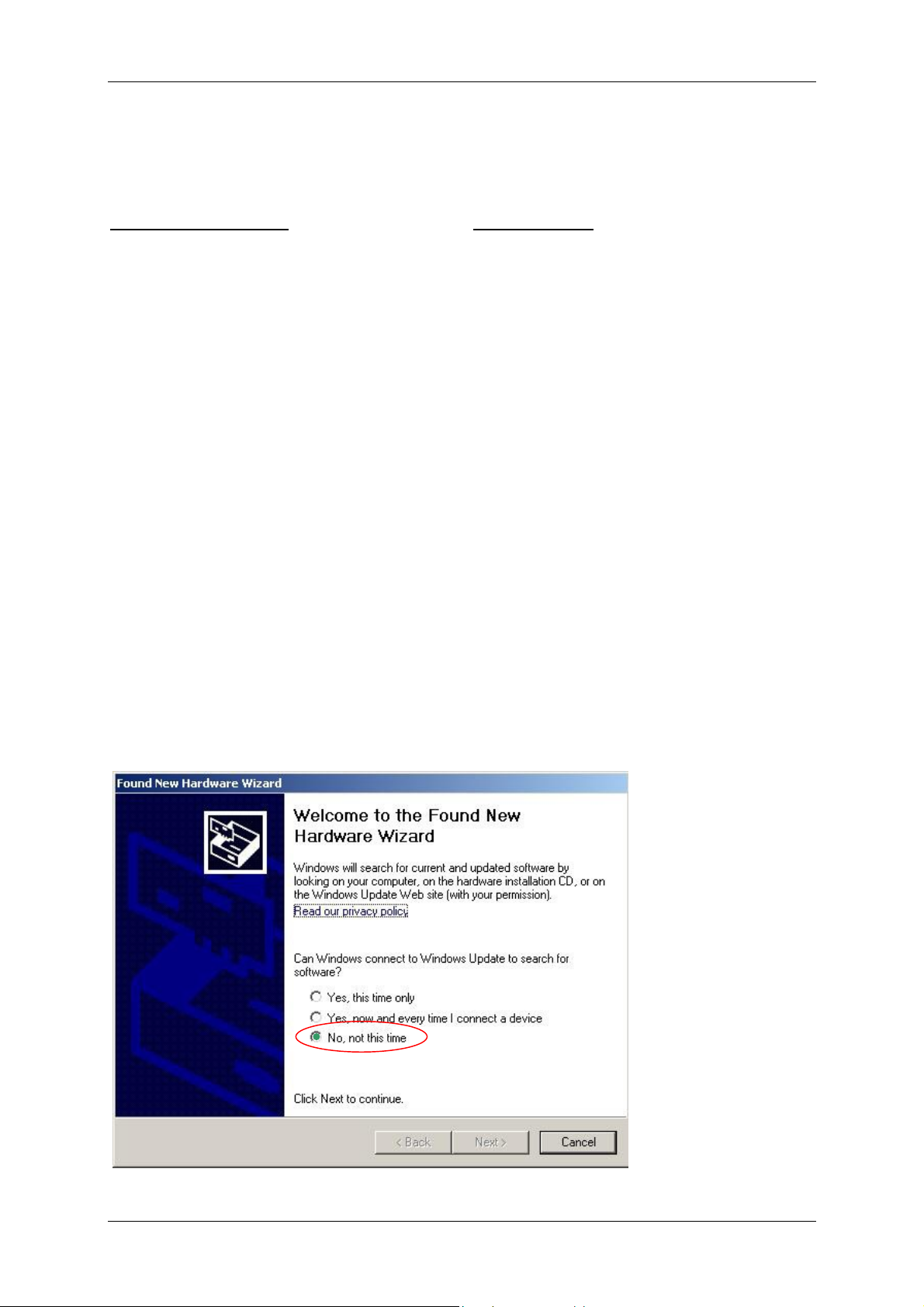
2.2.1 Step 1
In the wizard which now appears, select "No, not this time" and click on “Next” (this
dialogue appears with Windows XP only; for Windows 2000 start at 2.2.2).
Edition 06/2007
Page 6
CMWIN ENGLISH Page 6
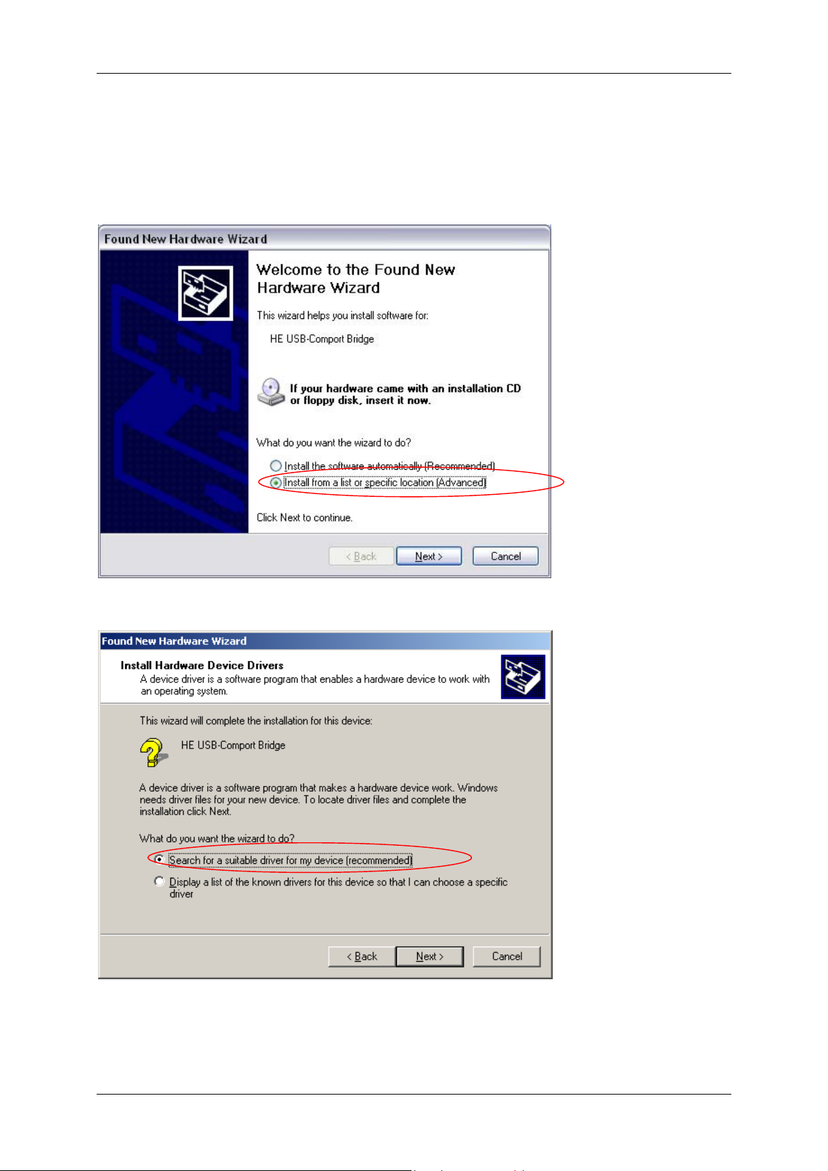
2.2.2 Step 2
In the following Wizard, select the button “Install software from a list or specific location
(for advanced users)” (XP) or “Search for a suitable driver for the unit (recommended)”
(Windows 2000), and confirm with “Next ”.
(Windows XP wizard)
(Windows 2000 wizard)
Edition 06/2007
Page 7
CMWIN ENGLISH Page 7
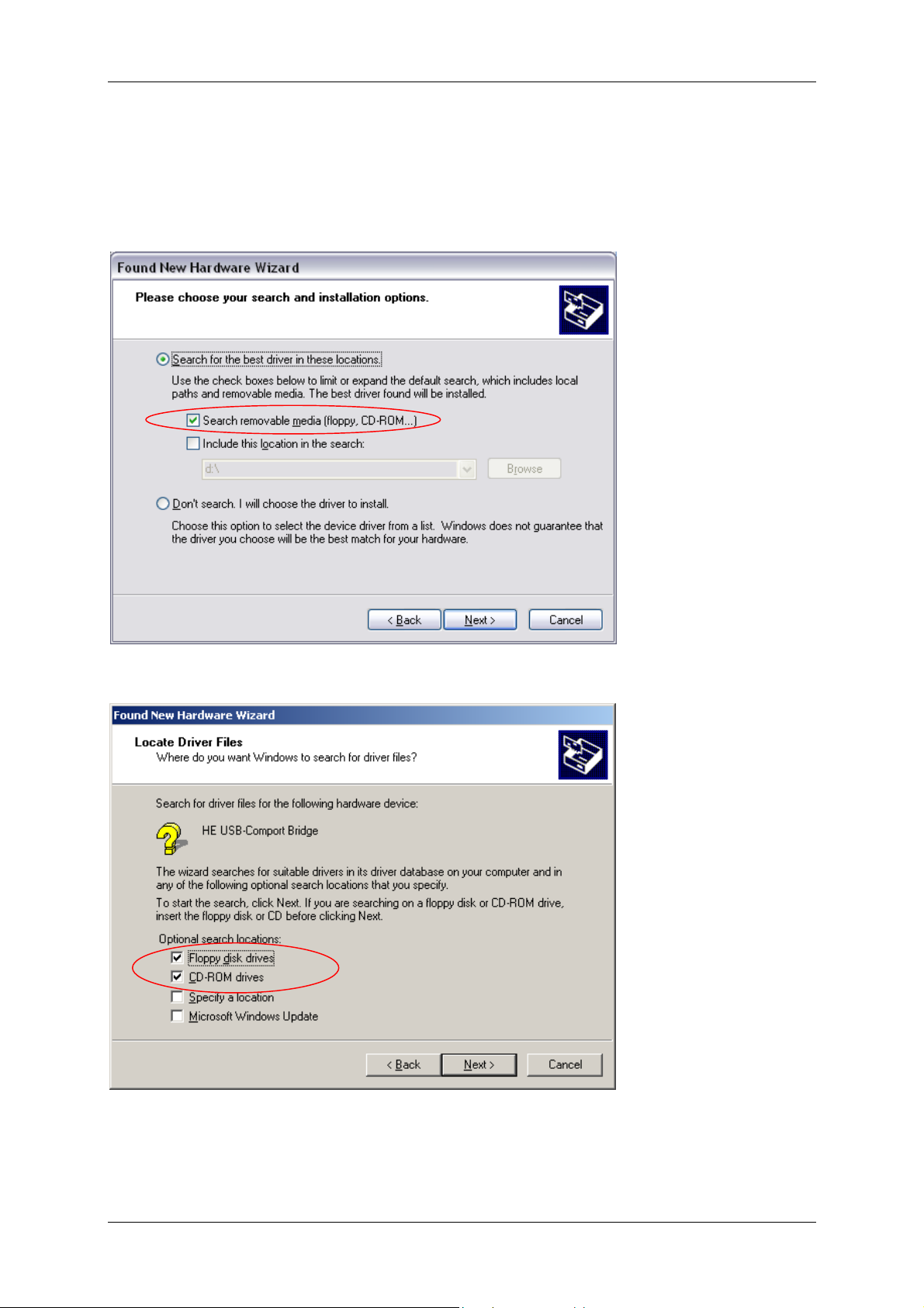
2.2.3 Step 3
Windows now tries to locate the driver files. Choose “Search removable media (floppy,
CD-ROM...)" (Windows XP) or "CD-ROM drives“ (Windows 2000). Now insert the CD-ROM
supplied in your CD-ROM drive.
(Windows XP wizard)
(Windows 2000 wizard)
Edition 06/2007
Page 8
CMWIN ENGLISH Page 8
2.2.4 Step 4
After Windows has searched the CD-ROM the driver files are installed.
NOTE:
A warning now appears with Windows XP telling you that the drivers are not certified by
Microsoft and could therefore cause harm to your computer. Select "Continue with
installation"; you can be sure that no harm will come to your computer.
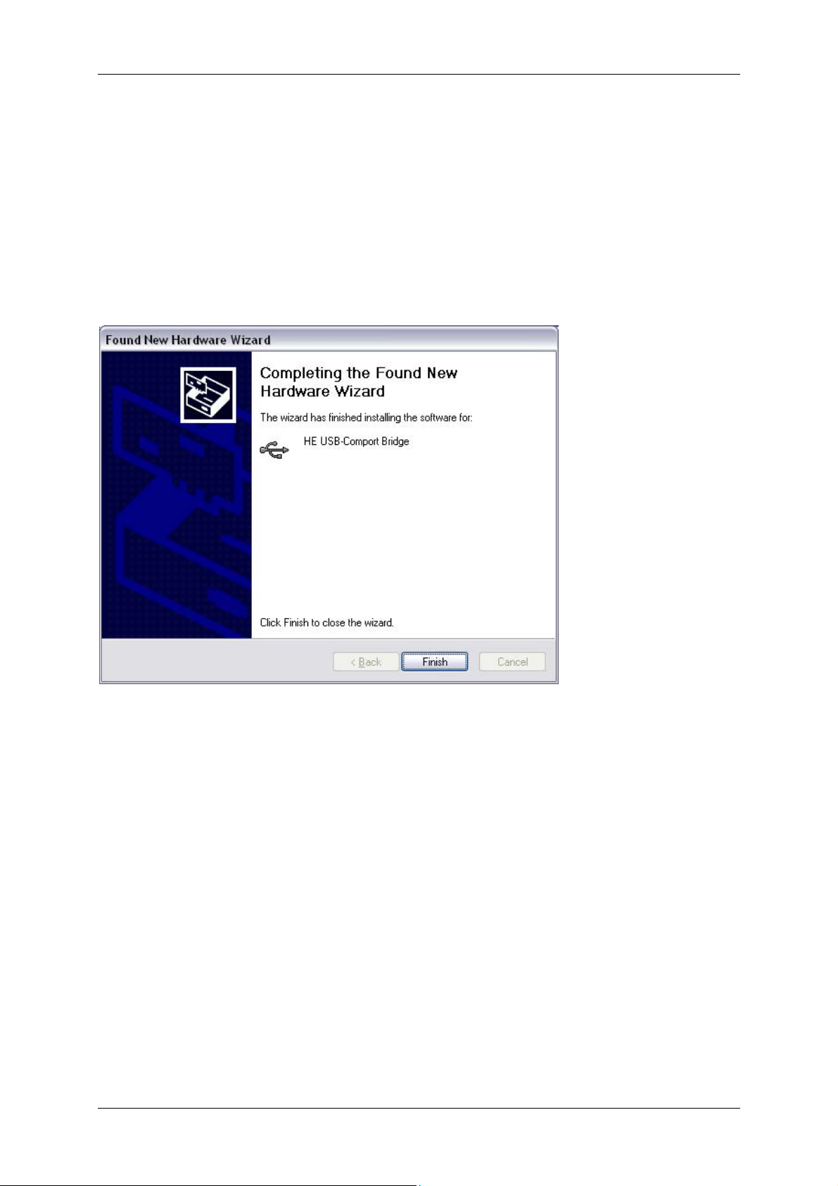
Successful installation is indicated in the window "Completing the Wizard" with the
message "The software for the following hardware has been installed”. Now click on
“Finish” to complete installation of the drivers.
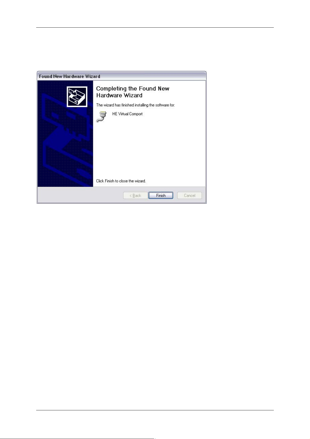
2.2.5 Step 5
NOTE: After installation of the first driver is completed, a second one is installed.
For the installation steps, see sections 2.2.1 to 2.2.4.
Edition 06/2007
Page 9
CMWIN ENGLISH Page 9
Successful installation is indicated in the "Completing the Wizard" window with the
message "The wizard has finished installing the software for: …". Now click on “Finish”
to complete installation of the drivers.
2.3 Installing CMWIN
• Call up the file “CMWIN_VXX_RXX-SETUP.EXE” in the “Installation” folder and follow the
instructions of the “Setup Wizard”.
2.4 Starting CMWIN
• If you have installed the program in the default path suggested by the Setup Wizard it is
located in the Start Menu under “Programs” → “HYDAC-ELECTRONIC CMWIN”. To
launch the program, click on “CMWIN”.
• When launching the program for the first time a window appears enabling you to select
the user interface language: German, English or French. Simply click on the language of
your choice with your mouse. Confirm by clicking on “OK”.
Edition 06/2007
Page 10

CMWIN ENGLISH Page 10
2.5 Approach of SMART sensors
A SMART sensor is an intelligent sensor with which the CMWIN-Software communicates.
• If the pass-through mode is not switched on (2.6.2), the CMWIN-Software
communicates with the HMG. In this case the HMG is the SMART sensor.
• If the pass-through mode is switched on (2.6.2), the CMWIN-Software
communicates with the sensor connected to the HMG.
2.6 Establishing a link with the SMART sensor
• Click on the dialogue box "SMART Sensors".
• "SMART-Sensor" opens in a new window.
• Click on "Interface" on the left of the window.
• Another window opens for interface settings.
• Set the interface as required (see 2.6.1 Setting the interface, 2.6.2 and 2.6.3
General Instructions on using Software).
• Once you have set the interface, click on "Apply", to apply the settings made or on
"Cancel" discard the changed settings.
• The interface settings window is closed.
• Click on "Link", to establish a link with the SMART sensor.
2.6.1 Setting the interface
• Click on the dialogue box "SMART Sensors" in the interface settings window.
• "SMART Sensor“ opens in a new window.
• Click on "Interface“ on the left of the window (when program is used for first time,
this step is carried out automatically).
• Another window opens to set the interface.
• Select the correct baud rate from the relevant dropdown menu.
■ Select "9600" as Baud rate for HMG 510.
■ Select "460800 USB" as Baud rate for HMG 3000.
• Select the correct port number from the relevant dropdown menu.
■ If several comports are available and you do not know which one the SMART
sensor is connected to, you can check which is correct in the Windows device
manager under "Ports (Com and LPT)“. E.g. HE Virtual Comport (COM5).
• You can also set the pass-through mode and multisensor mode, as described
under 2.6.2 and 2.6.3.
• If you have completed all the changes, click on "Apply", to apply the changes or
on "Cancel", to discard the changes.
Edition 06/2007
Page 11

CMWIN ENGLISH Page 11
2.6.2 Switching on or switching off the pass-through mode
The pass-through mode is required if communication is required with the SMART sensor
connected to the HMG directly from your PC.
• Click on "Pass-through mode" in the interface settings window.
• If it is possible to switch the pass-through mode both on or off at one port (or at
more than one), a new window opens to switch the pass-through mode on or off.
• In the dropdown menu select the port connected to the SMART sensor for which
you wish to switch the pass-through mode on or off.
• Click on "Switch on" to switch on the pass-through mode for the selected port or
on "Switch off" to switch off the pass-through mode for the selected port.
• An information window opens which you must confirm with "OK".
2.6.3 Switching on or switching off the multisensor mode
The multisensor mode is required if several sensors with a clearly allocated bus address are
connected to the same interface.
• Click on the box in front of "Multisensor mode“ to activate or deactivate the
multisensor mode.
• The bus address can be set by clicking "Set bus address".
• After estabishing a link with the SMART sensor you can change the bus address of
the sensor by clicking on "Set bus address“ on the left side of the main window.
• In both cases select the required setting in the dropdown menu.
• Important: in the multisensor mode some functions are restricted.
Edition 06/2007
Page 12

CMWIN ENGLISH Page 12
3 Using CMWIN
Note:
For all options, selections can only be made using the mouse.
3.1 Sensor information
Sensor information gives more precise information on the connected sensor.
• Click on the "SMART sensor" dialogue box.
• "SMART sensor" opens in a new window.
• Establish a link with the SMART sensor (see 2.6 Establishing a link with the
SMART sensor).
• Click on "Sensor information" on the left of the window.
• On the right side of the window, information appears on the SMART sensor
connected.
3.2 Viewing actual measured values of the SMART sensors in CMWIN
• To view actual measured values of the SMART sensor:
Click on the “SMART sensors” dialogue box.
“SMART sensor” opens in a new window.
Establish a link with the SMART sensor (see 2.6 Establishing a link with the
SMART sensor).
Click on "Sensor values" on the left of the window.
In the window on the right hand side, a table appears with sensor values.
"Channel"
"Measured value"
"Unit of measurement"
Plus, if supported by sensor:
"Min"
"Max"
The width of the colums can be altered as required.
To reset the min/max values, click on "Reset Min/Max values" under the viewing
area of the sensor values.
= lowest measured value
= peak measured value
= designation of measurement channel
= actual measured value
= unit of the particular measured value
3.3 Retrieving a Measurement Curve
There are three ways of doing this:
You can import a measurement curve from your connected device into CMWIN, open a
saved file, or retrieve a file that is already open.
Edition 06/2007
Page 13

CMWIN ENGLISH Page 13
3.3.1 Retrieving a File from the SMART sensor in CMWIN
• Opening a file stored in the SMART sensor (if supported by SMART sensor):
• Click on the dialogue box "SMART sensors".
• "SMART Sensor" opens in a new window.
• Click on "Sensor recordings“ on the left of the window.
• This displays on the right hand side all the recordings saved on the HMG or
sensor.
• Select one or more recordings from the list.
• Click on "open" in the line under the recordings.
• All selected recordings are opened in CMWIN, and the last recording to be opened
is shown in the display window. All recordings are displayed in the left hand
column with the name and number with which they are stored in the SMART
sensor.
• Close the "SMART sensor“.
• Now you can work with the recording (see point: "3.4" ff)
• The recording can be saved again afterwards (see point: "3.7.3").
• A file stored in a SMART sensor can be saved directly, if supported by the SMART
sensor.
• Click on the “SMART sensors” dialogue box.
• “SMART sensor” opens in a new window.
• Click on “Sensor recordings “ on the left hand side of the window.
• All of the recordings stored in the sensor are shown on the right.
• Select one or more recordings from the list.
• Click on “Save“ in the line under the recordings.
• “Save as“ opens in a new window.
• Repeat procedure until all selected files have been saved.
• The recordings are merely saved, not opened.
• Close the “SMART sensor” window to continue working with CMWIN.
3.3.2 Opening a measurement curve already saved on the PC
• Click on the “File“ dialogue box and select “Open“ in the dropdown menu. You
also have the option of clicking directly on “Open“ on the bottom left of the screen.
• Select the required recording in the relevant folder (file extension: *.herf“).
• To open recordings made with a previous version of the HMG (e.g. HMG 2020),
select “Legacy formats” as the file type in the dropdown menu (file extension:
*.hmg, *.cur, *pro).
• Click on the “File“ dialogue box. In the dropdown menu above the “Quit“ menu
item you will find a list of the most recently opened recordings (max. 8).
3.3.3 Retrieving an open file
• All open files are listed on the left hand side of the window and can be retrieved for
further work using the program by clicking on the file name.
Edition 06/2007
Page 14

CMWIN ENGLISH Page 14
3.4 Views of a measurement curve
There are four views of a measurement curve: Graph, Table, Recorded data, Description.
All four views can be selected either in the dropdown menu of the “View“ dialogue box or at
the top of the screen, directly underneath the “Tool bar“.
• Graph: displays the measurement curve as a function (for edit options, see
“Working on a Measurement Curve“and “Editing a Measurement Curve“).
The time is shown in the X axis, the measured values of the curves are shown in
the Y axis, the curves being shown in the relevant color (for hiding or showing, see
“Settings“).
• Table: table showing the measured values of the individual sensors recorded at a
particular point in time.
• Recorded data:
General: type of measurement curve, number of sensors, number of data
records, starting and end date of the measurement, etc.
Channels with their measurement ranges
• Description: Designation and comments entered for the curve. The designation
and comment can be changed or added here.
3.5 Working on a measurement curve
There are various options for working on and editing a curve. All editing functions can be
found in the dropdown menu of the “Graph“ dialogue box as well as at the bottom of the
screen.
3.5.1 Measure
• Click on the “Graph“ dialogue box and select “Tools“ in the dropdown menu and
“Measure“ in the submenu, or select “Measure“ at the bottom of the screen.
• “Measure“ is now highlighted at the bottom of the screen.
• When you move the mouse over the graph, the mouse pointer turns into a ruler.
• Move the ruler to a point in the graph and press the left mouse button.
• Crosshairs and the corresponding values of the intersection of these crosshairs
are shown on the X and Y axis. If you hold down the left mouse button you can
move the crosshairs in the graph.
• The intersection can be shifted as follows:
By moving the mouse over the crosshair you want to change (parallel to the
time axis or value axis of the sensors). When the mouse pointer changes to a
double arrow (R), click the left mouse button and shift the relevant axis to the
point from which you need the measured value.
By clicking on another point in the graph with the ruler.
Edition 06/2007
Page 15

CMWIN ENGLISH Page 15
3.5.2 Measuring difference
• Click on the “Graph“ dialogue box and select “Tools“ in the dropdown menu and
“Measure difference“ in the submenu, or select “Measure diff. “ at the bottom of the
screen.
• “Measure diff.“ is now highlighted at the bottom of the screen.
• When you move the mouse over the graph, the mouse pointer turns into a vernier caliper.
• Using the vernier caliper, select one of the two points between which you would like to
measure the distance and press the left mouse button.
• A crosshair in bold (each of the hairs consisting of two thin parallel lines) appears along
with a color-highlighted numerical value on each of the axes showing the distance.
• If you move the mouse over one of the axes a double arrow (R) appears. If you hold the
left mouse button down you can pull the thick line "apart" and drag one of the lines to the
level of the second point. The color-highlighted numerical value changes, indicating the
distance. You can repeat this with all four lines as often as you like.
• After selecting the first point you can also hold down the left mouse button and
immediately select the second point.
• Here, too, a new starting point can be repeatedly selected by clicking on another point in
the graph.
3.5.3 Tracker
• Click on the “Graph“ dialogue box and select “Tools“ in the dropdown menu and
“Tracker“ in the submenu, or select “Tracker“ at the bottom of the screen.
• “Tracker“ is now highlighted at the bottom of the screen.
• When you move the mouse over the graph the mouse pointer turns into a vertical broken
line.
• Click (left mouse button) on the approximate point in time for which you would like to
know the measured values.
• An indicating line appears vertically on the time axis on which the values of the individual
curves are marked by squares. The time and the individual measured values are colorhighlighted on the axes.
• If you hold the left mouse button down you can drag the line along the time axis whereby
the values are displayed. During tracking, you jump from one measured value to another.
• The indicating line can also be moved along the time axis by clicking on the Arrow
Up/Down buttons (lower right of screen underneath “Measured Value No.“) or by
actuating the Arrow Up or Arrow Down keys on the keyboard. By doing this, you track
each measured value.
• Clicking on another position in the graph will move the indicating line to that point.
3.5.4 Zoom In
• Click on the “Graph“ dialogue box and select “Tools“ in the dropdown menu and
“Zoom in“ in the submenu, or select “Zoom in“ at the bottom of the screen.
• “Zoom in” is now highlighted at the bottom of the screen.
• When you move the mouse over the graph the mouse pointer turns into a magnifying
glass with a plus sign.
• Only whole grid squares can be magnified.
Edition 06/2007
Page 16

CMWIN ENGLISH Page 16
• To zoom in on one of the grid squares, click on it and hold the left mouse button down.
You can select one or more grid squares by dragging the mouse and drawing a rectangle
around them. The selected portion is indicated by a thicker broken line.
• Release the left mouse button to zoom in on the selected portion, i.e. the selected portion
is displayed larger within the overall graph.
3.5.5 Zoom Out
• Click on the “Graph“ dialogue box and select “Tools“ in the dropdown menu and
“Zoom out“ in the submenu, or select “Zoom out“ at the bottom of the screen.
• “Zoom out“ is now highlighted at the bottom of the screen.
• When you move the mouse over the graph the mouse pointer turns into a magnifying
glass with a minus sign.
• Zooming out functions in a similar manner to zooming in. Select one or more grid squares
by dragging the mouse and drawing a rectangle around them.
• Release the left mouse button to display the view last shown in the overall graph in the
framed area.
3.5.6 Panning
• Click on the “Graph“ dialogue and select “Tools“ in the dropdown menu and “Pan“ in
the submenu, or select “Pan“ at the bottom of the screen.
• “Pan“ is now highlighted at the bottom of the screen.
• When you move the mouse over the graph the mouse pointer turns into a hand.
• Click on the graph and keep the left mouse button depressed.
• Using the mouse now shift the image in the required direction.
• Release the mouse button.
• Panning is only done in whole grid units.
3.5.7 Full view
• Click on the “Graph“ dialog and select “Full view“ in the dropdown menu, or select
“Full view“ at the bottom of the screen.
• The graph now shows the entire time and amplitude range of the measurement.
3.5.8 Automatic scale
• Click on the “Graph“ dialogue box and select “Automatic scale“ in the dropdown
menu, or select “Automatic“ at the bottom of the screen.
• The scale settings selected (see section 3.5.9) are applied to the current recording.
Edition 06/2007
Page 17

CMWIN ENGLISH Page 17
3.5.9 Scale Settings
• Click on the “Graph“ dialogue box and select “Scale settings“ in the dropdown menu,
or select “Scale settings“ at the bottom of the screen.
• Selecting the resolution type and scaling type (refers to the default scale settings):
Resolution settings: Click on the upper arrow button. A dropdown menu opens in which
you can choose among the various resolution settings.
< best fit resolution
< fine resolution
< medium resolution
< coarse resolution
< 1-2-5 resolution:
largest and smallest value of the current display range. Scaling is in
increments of 0.1, 0.2, 0.5, 1, 2, 5, 10, 20, 50, etc. If a value is exceeded, the
next larger value is used as the scaled range. Example: if the difference
between the smallest and largest value is 49 bar, scaling is from the smallest
value to the largest value + 50, if the difference were 51 bar, scaling would be
from the smallest value to the largest value +100)
Scaling type of channels:
< Scale all channels separately: when default scaling is applied, each channel is
rendered optimally in a separate window with its maximum and minimum
value.
< Scale channels with the same unit jointly: when default scaling is applied the
smallest and largest measured value overall is used for scaling between these
two values. The same scaling is applied to all channels with the same unit.
• Click on “OK“ to apply the modified scale settings or “Cancel“ to discard your changes.
3.5.10 Keyboard Navigation
The coarser the resolution, the "rounder" the scaling in
the Y axis, meaning the measured values along the Y
axis can be more easily read at first glance.
This resolution is in reference to the difference between the
• Click on the “Graph“ dialogue box and select “Tools“ in the dropdown menu and
“Keyboard navigation“ in the submenu, or select “Keyboard navig. “ at the bottom of
the screen.
• “Keyboard navig. “ is now highlighted at the bottom of the screen.
• Using the keyboard arrow keys you can shift the viewing area to the right, left, up and
down. Every time you press an arrow key the viewing area is shifted by one grid unit in
the relevant direction.
• If you press the Shift key at the same time, every time you hit the → or ← key the time
axis of the graph is enlarged or reduced respectively. This corresponds to a zoom
function, but for the time axis only.
• If you press the Shift key while hitting the ↑ or ↓ key, you can change the scaling of the Y
axis. This corresponds to a zoom function, but for the Y axis only.
3.5.11 Remark
• Click on the “Graph“ dialogue box and select “Remark“ in the dropdown menu, or
select “Remark“ at the bottom of the screen.
• “Remark“ is now highlighted at the bottom of the screen.
• When you move the mouse over the graph the mouse pointer turns into a square
connected with the "handle" (cf. dot) by a line.
• Using the "handle", click on the approximate position you would like to insert a remark.
Edition 06/2007
Page 18

CMWIN ENGLISH Page 18
• A Remark window opens. It is subdivided into three parts: text, style and anchor.
Remark text
< The remark text %T: %V automatically appears, which serves as a
placeholder, “Anchor to measured value“ being activated by a checkmark in
the white checkbox.
< Entering placeholders using %T for the actual time and %V for the actual
measured value is not possible unless “Anchor to measured value“ is
activated.
< If you leave the placeholders %T, %V and click on “OK“, you automatically
get a measured value for a specific time (= quick and easy method for
entering measured values in the graph).
< Additional text can be entered, or the placeholders can be deleted.
Font
< Here you can change the font size and color and put the text in “Bold“,
“Italic“ or “Underline“ by clicking the respective checkbox.
< A blue-highlighted box with “Set style as default“ appears. To use these
settings as the default font settings, left-click on this box. A window pops up
containing the message “The current style has been set as default“.
Confirm with “OK“. The message window closes.
Anchor
< The checkbox in front of “Anchor to measured value“ is initially activated
(i.e. checked). To enter text without anchoring it to a measured value,
deactivate this function by clicking on the checkbox.
< If the checkbox is activated you can select the sensor (measurement channel)
to which the remark is to be anchored (checkmark in the checkbox of the
respective sensor).
< You can also indicate the time at which the remark is to be anchored to the
measurement curve. You can either enter the time in ms or change it by
clicking the arrow keys next to the time box with your mouse. One click on one
of the arrows => corresponds to a change by the preset measurement rate.
• When you are finished entering your settings, confirm by clicking on “OK“.
• If you click on “Cancel“ your comments will be discarded.
• After clicking on “OK“ the Remark window closes and the remark box can now be seen.
If anchoring has been activated, the remark box is linked to the selected curve by a
line. The circle at the end of the line shows which measured value the remark
refers to.
If anchoring has been deactivated, only the remark is visible.
• The remark can be edited and shifted later providing the remark function has been
enabled.
The position at which the remark is anchored to the measurement curve can be
shifted by moving the mouse pointer over the anchor position. If you hold the left
mouse button down you can drag the anchor to the required position. If you have
entered the placeholder it is adjusted accordingly when you release the mouse
button. The anchor point is always a measured value as the remark is anchored
to the measurement curve.
The remark box itself can be shifted by moving the mouse pointer over the remark
box (it is now blue-highlighted; the square turns into a hand pointer, 3 handles
appear in the lower right corner). Click and hold down the left mouse button and
move the remark box to the required position.
Edition 06/2007
Page 19

CMWIN ENGLISH Page 19
To edit the text or manually enter another "anchor time", click on the 3 handles in
the lower right corner.
The remark box opens again.
“OK“, “Cancel“ and “Delete“ appear in the bar at the bottom of this window.
< “OK“ = apply changes
< “Cancel“ = close window and discard changes
< “Delete“ = delete the entire remark
3.5.12 Remarks List
• Click on the “Graph“ dialog and select “Remarks list“ in the dropdown menu, or select
“Remarks list“ at the bottom of the screen.
• A window with the remark list opens.
• All remarks are listed along with the particular X axis allocated, their anchor, their position
on the X axis (time), and the relevant remark text.
• The entire text of the blue-highlighted remark appears in the lower box.
• Click on “Delete“ in the bar beneath this window to delete the blue-highlighted remark.
• Click on “OK“ to close the window with the remark list.
3.5.13 Settings
• Click on the “Graph“ dialogue box and select “Settings“ in the dropdown menu, or
select “Settings“ at the bottom of the screen, or click on one of the scales of the Y axis.
• A window with the settings is opened containing a number of tabs (each tab can be
selected by clicking on the tab name):
“General“ tab (appears first when opening the window):
< The recording time and the actual output range are indicated. The actual
output range can be changed manually by entering other time values.
< You can also choose whether the time or the measurement range of a sensor
is to be scaled along the X axis (e.g. for a P/Q diagram).
< By clicking the checkbox for “Left Y axis“ and “Right Y axis“ you can
determine which channels are to be displayed on the Y axis (right- or left-hand
side of the graph).
Individual measurement channel tabs:
< Under Designation you can give the measurement channel a name, e.g.
"system pressure" if the system pressure of an equipment item was measured
in this measurement channel using a pressure transducer.
< The following can be entered by hand in the second section: the full indication
range (the range shown when selecting “Full indication range“) and the
actual indication range (range currently shown).
< Third section: the type of display can be set and whether or not the associated
measurement series is to be displayed. The measurement series is hidden
when you deactivate the checkbox after “Show measurement series“ (i.e.
click on the checkbox so that the checkmark disappears). You can also select
the color for the measurement series from a list. You can access the list by
clicking on the arrow button next to the color. You can select the line type by
clicking on the arrow button. Options: “Solid line“, “Dotted line“ and “Dash
dotted line“.
< Last section: you can enter a remark for the measurement series.
• Click on “OK“ to save your changes or “Cancel” to discard them.
Tip
: If you only want to change the settings of one channel, e.g. hide it, click on this
channel in the upper right next to the graph view. The Settings window opens in
which the tab of this measurement channel is preselected.
Edition 06/2007
Page 20

CMWIN ENGLISH Page 20
3.5.14 Back
• To undo changes in the view, click on the “Graph“ dialogue box and select “Back“ in
the dropdown menu, or select “Back“ at the bottom of the screen. You can do this as
many times as there are changes.
3.5.15 Forwards
• To redo changes which have been “Undone” in the graph view click on the “Graph“
dialogue box and select “Forwards“ in the dropdown menu, or by select “Forwards“ at
the bottom of the screen. You can do this as many times as there are changes to redo.
3.5.16 Save View
• To save a zoomed view, for example, click on the “Graph“ dialogue box and select
“Save view“ in the dropdown menu, or select “Save view“ at the bottom of the screen.
• A window opens where you can enter a name and a description for the saved view.
• Click on “OK” to save the view or “Cancel” to discard it and return to the graph.
3.5.17 List Views
• "List views" is used to jump back and forth between various saved views.
• To view a saved view or select or rename it, click on the “Graph“ dialogue box and
select “List views“ in the dropdown menu, or select “List views“ at the bottom of the
screen.
• A window with the saved views opens.
• This window is divided in two: the upper part contains a listing of all views with their
names, the bottom part a description of the view currently selected.
• You can select any view by clicking on it with your mouse. When selecting a view, the
view is shown in the background and your description appears in the lower section.
• “OK“, “Delete“ and “Rename“ appear in the bar at the bottom of this window.
OK = closes the window
Delete = deletes the selected view
Rename = to rename the selected view. When this option is selected, a
window for renaming the view is opened. Enter a new name
and confirm with “OK” to save it, or click on “Cancel” to retain the
old name.
Edition 06/2007
Page 21

CMWIN ENGLISH Page 21
3.5.18 Create Picture
• Click on the “Graph“ dialogue box and select “Create picture“ in the dropdown menu,
or select “Create picture“ at the bottom of the screen.
• A new window opens in which the actual graph view is shown as a picture so to speak.
• In the left part of the window you have the following options.
Transparent = the created picture is transparent so that the underlying picture is
visible, thus enabling two curves to be compared visually.
Copy = the picture is copied to the Windows Clipboard for use in other
documents.
Save = opens a window for saving the picture in JPG format.
Edition 06/2007
Page 22

CMWIN ENGLISH Page 22
3.6 Editing a Measurement Curve
You have various options for editing and processing a curve. All of the functions for this are
located in the dropdown menu of the “Edit“ dialogue box. “Extract Recording... “ and
“Curve Overlay... “ create a measurement which is filed in the left-hand box when files are
open, the files being named “Recording X“ (x = sequential number). They are not stored
automatically however.
3.6.1 Extract Recording
• To create a copy of the measurement currently open or extract a zoomed portion of the
measurement, click on the “Edit“ dialogue box and select “Extract Recording“ in the
dropdown menu.
• The measurement is filed in the left box of the open files and can now be edited without
any changes being made to the original file.
• You can save this file under a name of your own choosing (see “3.7.2 Save“ or “3.7.3
Save As“).
3.6.2 Curve Overlay
• Overlaying two measurement curves is useful for comparing measurements, e.g. the
measurement of a machine cycle taken three months ago vs. its current condition.
• To superimpose two measurement curves, click on the “Edit“ dialogue box and select
“Curve Overlay“ in the dropdown menu (Note
sampling interval.
• The “Wizard for Overlay“ opens in a new window.
• You are now asked to select a 2
the curve currently open.
• Click on the arrow button to get a list of all open curves recorded using the same
sampling rate.
• To see all the curves possible, click on the arrow button next to the name.
(The list is empty if no curves with the same sampling rate are open.)
• Click on the curve you would like to superimpose, followed by clicking on “Next“ in the
bar at the bottom of the window.
• The second recording is opened in the same window as the original recording and a
prompt for coordinating the time of the second recording appears in the wizard. (Shifting
can only be done along the time axis.)
• The recording can be adjusted roughly using the mouse and clicking on the scrollbar,
keeping the left mouse button pressed, and shifting the recording to the approximate
position desired.
• To position the recording precisely, click on the arrow buttons to the right (<) and left (;)
of the scrollbar until the second recording is positioned as desired.
• To overlay the curves click on “Complete“ in the bar at the bottom of the window.
• Click on “Cancel“ to cancel the overlay.
nd
recording, i.e. the recording to be used for overlaying
3.6.3 Time-Shift Channels
: possible only for curves with the same
• To time-shift one or more channels in a measurement, click on the “Edit“ dialogue box
and select “Time-shift channels“ in the dropdown menu.
• The “Wizard for Time-shifting of channels“ opens.
• Select the channel you wish to time-shift in the dropdown menu.
• The measurement channel can be adjusted roughly by clicking on the scrollbar, keeping
the left mouse button pressed and dragging to the right or the left.
• To position the recording precisely, click on the arrow buttons to the right (<) and left (;)
of the scrollbar or press the right (→) and left (←) arrow keys on the keyboard until the
measurement channel is positioned as desired.
Edition 06/2007
Page 23

CMWIN ENGLISH Page 23
• Click on “Close“ to return to the main window.
• The time axis is now marked with an asterisk (*time [ms]). This means that at least one of
the curves has been time-shifted.
• To undo the shifts, return to the “Wizard for Time-shifting of channels“ (see above).
• Click on “Delete“ to undo the shift of the active channel (see name in upper box). Click
on “Delete All“ to remove the time shift on all channels.
• Once you have undone all time shifts the time axis no longer features an asterisk.
• Click on “Close“ to return to the main window.
3.6.4 Add Calculated Channel
• To calculate a channel from one or more measurement channels, click on the “Edit“
dialogue box and select “Add calculated channel“ in the dropdown menu.
• A new window opens for calculating the channel.
• Enter the mathematical formula for the virtual channel in the formula input box at the top.
The formula can be comprised of numbers, measured values, arithmetical operators and
functions. For measured values, use "S1...Sn" in the formula.
Example: 5 * ((S1 + S2) / 2)
• For detailed information on the formula contents and symbols, click on “Help“ located in
the line below on the right. Click on “Help“ again to close the window.
• The unit of the channel being calculated can be entered in the “unit” input box.
• Select the number of decimal places for the measured values displayed (0 .. 8 decimal
places) from the ”Decimal places” box.
• After entering a formula to be calculated, click on “Calculating“ in the line at the bottom
of the window. The computed curve is now inserted.
• This process can be repeated as often as desired.
• After entering all the channels to be calculated and computing them, click on “OK“ to
close the window.
• Clicking on “Cancel“ also closes the window but the calculated channels are removed
again.
• On the right of the screen you will now find the calculated channels. The settings can be
changed here as for any other channel. Calculated channels are always marked with an
asterisk (*).
3.6.5 Add a Filtered Channel
• To remove noise from a measurement, for example, click on the “Edit“ dialogue box and
select “Add a Filtered Channel“ in the dropdown menu.
• A window for filtering the channel opens.
• Clicking on the button next to the channel input box causes a dropdown menu to appear
in which all channels are listed. Select the channel to be filtered.
• Clicking on “Settings“ to open the channel settings window. Click on “OK“ to save any
changes you might have made, or “Cancel “to discard them.
• By moving the arrow on the bar “Filter strength” with your mouse the degree of filtering
is changed. Changes can be monitored in the display pane of the graph.
• When the filter setting desired is located, click on “OK“ and the channel is inserted
permanently and can be edited like any other channel. Filtered channels are also always
marked with an asterisk (*).
• Click on “Cancel“ to cancel the action.
Edition 06/2007
Page 24

CMWIN ENGLISH Page 24
3.6.6 Remove Channels
CAUTION: This action cannot be undone!
• To remove, i.e. not just hide, individual measurement channels, click on the “Edit“
dialogue box and select “Remove channels“ in the dropdown menu.
• A new window opens in which all the channels of the recording are listed.
• Select the channels to be removed by clicking on the checkbox next to their name. A
checkmark appears in the checkbox.
• You can undo your selection by clicking on the checkbox again so that the checkmark is
removed.
• When you have selected all of the channels to be removed, click on “OK“ at the lower
edge of the window.
• Click on “Cancel“ to cancel the action.
3.7 File Dialogue
The dropdown menu of the “File“ dialogue box contains various possibilities for retrieving,
saving, etc. recordings.
3.7.1 Open
• See”3.3 Retrieving a Measurement Curve”
3.7.2 Save
• To save a recording, click on the “File“ dialogue box and select “Save“ in the dropdown
menu, or click on “Save“ at the bottom left of the window.
• If the file has already saved no window opens; only the changes are saved.
• If the recording has not yet been saved, the “Save recording as…“ window opens.
3.7.3 Save As
• To save a file which hasn't been saved or to save a file under another name, click on the
“File“ dialogue box and select “Save as…“ in the dropdown menu, or click on “Save
as…“ at the bottom left of the window.
• The “Save as…“ window opens.
3.7.4 Save All
• To all changes in all files, click on the “File“ dialogue box and select “Save all“ in the
dropdown menu, or click on “Save all“ at the bottom left of the window.
• If all recordings have been previously saved, saving occurs without any new window
opening.
• If one or more of the recordings have not yet been saved, the “Save recording as…“
window opens.
3.7.5 Export
The export function enables you to save measured data in a format that can be exported to a
spreadsheet program (e.g. Excel), for example.
• To export a file, click on the “File“ dialogue box and select “Export…“ in the dropdown
menu, or click on “Export…“ at the bottom left of the window.
• Now the “Export data“ window opens.
Edition 06/2007
Page 25

CMWIN ENGLISH Page 25
• Select the time range to be exported:
“Whole time range“
“Displayed time range“
• Select the channels to be exported:
“All channels“
“Displayed channels“
• Decide how unit of measurement should be displayed:
“Without unit“ or
“Separate row“
• Select the data format in which the recording is to be saved:
“Text (separated by tabs)“
“CSV (separated by commas)“
“Formatted text (separated by spaces)“
“User-defined ASCII/ANSI Format“
• Select the delimiter characters (for “User-defined ASCII/ANSI Format“ only):
“No quotation marks“
“Single quotation marks (‘)“
“Double quotation marks (")”
• Select the separators (for “User-defined ASCII/ANSI Format“ only):
“Space“
“Tab“
“List separator“
“Other“
• Select the column width (for “User-defined ASCII/ANSI format“ only):
“Without fixed width“
“Automatic optimum width“
“Fixed column width“
• Export folder:
Click on button next to input box.
A window opens enabling you to browse for the folder.
• File name:
“Keep name of recording“
“Ask for new name“
• File extension (for User-defined ASCII/ANSI format only):
You can manually enter the file extension here.
3.7.6 Create PDF Document
• To save a recording as a PDF file, click on the “File“ dialogue box and select “Create
PDF Document…“ in the dropdown menu, or click on “Create PDF Document“ at the
bottom left of the window.
• The “Create PDF“ window opens.
• Select the path in which you want the recording to be saved as a PDF.
• You can “Keep the name of the recording“ as the file name or click on the arrow button
and select “Ask for new file name“ from the dropdown menu.
• In the upper section you can select whether the recording is to be stored in black & white
(“Monochrome“) and whether the PDF file is to be opened directly after being created
(“Show PDF document“).
• In the lower section you can decide which portions of the recording are to be contained in
the PDF document by clicking on the checkbox before the particular portion.
• Click on “Create PDF“ to create the pdf document.
• Click on “Cancel“ to cancel the action.
Edition 06/2007
Page 26

CMWIN ENGLISH Page 26
3.7.7 Print
• To print a recording, click on the “File“ dialogue box and select “Print“ in the dropdown
menu, or click on “Print“ at the bottom left of the window.
• The “Print“ window opens.
• In the upper part you can choose whether you want to print the recording in black & white
only (“Monochrome“).
• In the lower section you can decide which portions of the recording are to be contained in
the printout by clicking on the checkbox before the particular portion.
• Click on “Print“ at the bottom of the window.
• Click on “Cancel“ to cancel the action.
3.7.8 Close
• To close the measurement curve you are currently editing, click on the “File“ dialogue
box and select “Close“ in the dropdown menu, or click on “Close“ at the bottom left of
the window.
3.7.9 Close All
• To close all open measurement curves, click on the “File“ dialogue box and select
“Close all“ in the dropdown menu, or click on “Close all“ at the bottom left of the
window.
• If you have not saved your recordings, you are prompted to do so.
3.8 Managing sensor configuration of the SMART sensors in CMWIN
3.8.1 Managing the sensor configuration (only if supported by sensor)
Using CMWIN you can read out the actual configuration from the SMART sensor connected
to the HMG in the pass-through mode, add comments to it or transfer a configuration stored
on your PC to the SMART sensor.
• Click on the “SMART sensors“ dialogue box.
• “SMART sensor“ opens in a new window.
• Establish a link to the SMART sensor and switch on the pass-through mode, as
described in 2.6 Establishing a link with the SMART sensor or 2.6.2.
• After establishing the link, select "Manage sensor configuration“ on the left of the
window.
• On the right of the window "Manage sensor configuration" appears.
• In the dropdown menu, select the required group element and insert your comments, if
required.
• Click on "Read out from sensor", to store the actual sensor configuration in your PC.
• Click on "Transfer to sensor", to transfer a configuration stored on your PC to the
sensor and therefore to re-configure the sensor.
Edition 06/2007
Page 27

CMWIN ENGLISH Page 27
3.8.2 Managing sensor configuration files
It is also possible to load a configuration file stored in the PC onto the HMG 3000 or to store
a configuration file stored in the HMG 3000 onto your PC.
• Click on the "SMART-Sensors" dialogue box.
• "SMART sensor“ opens in a new window.
• Establish a link to the SMART sensor and switch on the pass-through mode, as
described in 2.6 Establishing a link with the SMART sensor or 2.6.2.
• After establishing the link, select "Sensor configuration files“ on the left of the
window.
• On the right of the window "Configuration files" appears and all of the sensor
configuration files stored on the HMG are listed.
• Click on "Upload", to transfer a file saved on your PC to the HMG.
• Click on "Save", to likewise save a file stored on the HMG onto your PC.
• Click on "Update", to display the changes carried out in the HMG.
3.9 Sensor dialogue
Important: The sensor dialogue is only possible if this is supported by the SMART-Sensor.
• Click on the dialogue box "SMART sensors".
• "SMART sensor“ opens in a new window.
• Establish a link to the SMART sensor and switch on the pass-through mode, as
described in 2.6 Establishing a link with the SMART sensor or 2.6.2.
• After establishing the link, select, "Sensor dialogue" on the left hand of the window.
• On the right of the window, the main menu appears with the menu points which
correspond to the menu points of the particular sensor.
• The continuing menu navigation corresponds to the menu navigation of the particular
SMART sensor. For further instructions please consult the operating instructions of
your SMART sensors.
Edition 06/2007
Page 28

CMWIN ENGLISH Page 28
3.10 Extras
3.10.1 Options
• Click on the “Extras“ dialogue box and select “Options“ in the dropdown menu.
• The Options window opens with the following setting options:
Options folder
The configuration file of CMWIN is stored in the Options folder. If you do not
specify a folder, this file (CMWINConfig.xml) is stored in the folder in which the
CMWIN.exe application is also located.
If more than oneuser is working with CMWIN, each user can create their own
Options folder. When the user selects this folder after launching
uses the configuration customized by the user. This enables different users to
each work with their own customized configuration settings
Working folder
When saving or opening recordings or settings, the folder selected here is
automatically accessed.
• Language
Click on the box after the "Language" box. It shows the language currently in use.
There is an arrow button next to it.
Click on this button; a dropdown list opens.
Select the required language using the mouse.
• Click on "OK", to apply the changes or on "Cancel", to keep the old settings.
CMWIN, CMWIN
3.11 Help
3.11.1 About CMWIN
• Click on the “Help“ dialogue box and select “Info…“ in the dropdown menu.
• A window opens containing a link to the HYDAC website and information on the version
of CMWIN you are using.
Edition 06/2007
Page 29

CMWIN ENGLISH Page 29
HYDAC ELECTRONIC GMBH
Hauptstr. 27
D-66128 Saarbrücken
Germany
Web : www.hydac.com
E-mail : electronic@hydac.com
Tel.: +49-(0)6897-509-01
Fax: +49-(0)6897-509-1726
HYDAC Service
If you have any questions concerning repairwork, please don’t hesitate to contact HYDAC
Service:
HYDAC SERVICE GMBH
Hauptstr. 27
D-66128 Saarbrücken
Germany
Tel.: +49-(0)6897-509-1936
Fax: +49-(0)6897-509-1933
Notice
The information and particulars provided in this manual apply to the operating conditions
and applications described herein. In the event of deviating applications and/or operating
conditions, please contact the respective HYDAC department concerned.
If you have any questions, suggestions, or encounter any problems of a technical
nature, please contact your HYDAC representative.
All technical details are subject to change without notice.
Trademarks: Where trademarks of other companies are used, these relate exclusively to the products of those companies.
Edition 06/2007
 Loading...