

Page 1
Condition Monitoring Unit
CMU 1000
User manual
(Translation of original manual)
Revised 17.12.2009 HYDAC ELECTRONIC GMBH Mat.-No.: 669749
Page 2

Condition Monitoring Unit CMU 1000 Page 2
Revised 17.12.2009 HYDAC ELECTRONIC GMBH Mat.-No.: 669749
Page 3

Condition Monitoring Unit CMU 1000 Page 3
Table of Contents
General...........................................................................................................................9
1
1.1 Previous Knowledge..............................................................................................9
1.2 Structure of the Manual.........................................................................................9
1.3 Copyright Protection ...........................................................................................10
1.4 Note on Warranty .................................................................................................10
1.5 Declaration of Conformity .........................................................................10
2 Safety ...........................................................................................................................11
2.1 General Safety Precautions ................................................................................11
2.2 Proper/Designated Use .......................................................................................12
2.3 System Configuration..........................................................................................12
3 Setup and Function.....................................................................................................13
3.1 Hardware Setup....................................................................................................13
3.2 Control Elements/Connections ..........................................................................13
3.3 Terminal Allocations............................................................................................14
3.4 Examples of Connections ...................................................................................16
3.4.1 SMART sensors .................................................................................................16
3.4.2 Standard HSI Sensors ....................................................................................17
3.4.3 Standard Analog Sensors ..................................................................................17
3.4.4 SMART Sensors and Standard Analog Sensors................................................17
3.4.5 GSM Module CSI-F-10......................................................................................18
4 Installation and Initial Operation ...............................................................................19
4.1 Installation Guidelines.........................................................................................19
4.2 Control Element on the Device...........................................................................20
4.3 Power Supply Connection ..................................................................................20
4.4 Behavior when Switching On/Restart ................................................................21
4.4.1 No CM Program Available in the Device ........................................................21
4.4.2 CM Program Available in the Device ..............................................................21
5 Basic Settings/Menu Structure..................................................................................23
5.1 Configuration on the Device ...............................................................................23
5.1.1 Menu Structure for Operation on the Device ..................................................23
5.1.2 Key Functions during Operation on the Device .............................................. 24
5.2 Configuration Using CMWIN PC Software.........................................................25
5.2.1 Direct Connection ........................................................................................... 25
5.2.2 Direct Connection via HSI Bus .......................................................................29
5.2.2.1 Device Connection via CSI-B-2 Interface Module....................................... 29
5.2.2.2 Connection Setup via CSI-B-2 Interface Module ........................................30
5.2.2.3 Device Connection without CSI-B-2 Interface Module................................ 32
5.2.2.4 Connection Setup without CSI-B-2 Interface Module..................................32
Revised 17.12.2009 HYDAC ELECTRONIC GMBH Mat.-No.: 669749
Page 4

Condition Monitoring Unit CMU 1000 Page 4
5.2.3 Modem Connection.........................................................................................37
5.2.3.1 Device Connection/Pin Connections........................................................... 37
5.2.3.2 Establishing Connection with GSM Radio Module CSI-F-10 ......................38
5.2.3.3 Connection Setup with CMU 1000 using GSM Mobile Network..................42
5.2.4 TCP Connection .............................................................................................45
5.2.4.1 Device Connection......................................................................................45
5.2.4.2 Connection Setup........................................................................................45
5.2.5 Actions ............................................................................................................ 48
5.2.5.1 Display Device Status .................................................................................48
5.2.5.2 Display Device Information .........................................................................49
5.2.5.3 Sensor Values............................................................................................. 49
5.2.5.4 Managing Recordings .................................................................................50
5.2.5.5 Performing a Dialog ....................................................................................50
5.2.5.6 Managing Configurations ............................................................................55
5.2.5.7 Set bus address ..........................................................................................58
5.2.5.8 Managing Sensor Constellations ................................................................59
5.2.5.9 Display Input Values ...................................................................................60
5.2.6 Extras..............................................................................................................61
5.2.6.1 Update Firmware.........................................................................................61
5.2.6.2 Set Password Protection............................................................................. 64
5.2.6.3 Change Password....................................................................................... 65
5.2.6.4 Removing Password Protection.................................................................. 65
5.2.6.5 Send Commands ........................................................................................65
6 CM Editor.....................................................................................................................66
6.1 Menu Bar...............................................................................................................67
6.1.1 File .................................................................................................................. 67
6.1.2 CM Program ...................................................................................................68
6.1.3 Grouping ......................................................................................................... 72
6.1.4 Device.............................................................................................................72
6.1.5 Sensor Constellation.......................................................................................73
6.1.6 Sensor Configuration ...................................................................................... 75
6.1.7 Extras..............................................................................................................77
6.2 Window Divisions ................................................................................................ 78
6.2.1 "Function Properties" Window ........................................................................78
6.2.2 "Function List" Window ...................................................................................78
6.2.3 "Linked Functions" Window ............................................................................ 78
6.2.4 "Functions" Window........................................................................................78
7 CM Program Functions...............................................................................................79
7.1 General Information Concerning Functions...................................................... 79
7.1.1 Inputs / Outputs ..............................................................................................79
7.1.1.1 Numerical Values........................................................................................79
7.1.1.2 Boolean Values...........................................................................................79
7.1.2 Parameters ..................................................................................................... 80
7.1.2.1 Numerical Parameters ................................................................................80
7.1.2.2 Whole Number ............................................................................................80
7.1.2.3 Entry List .....................................................................................................80
7.1.2.4 Boolean Parameters ...................................................................................80
7.1.2.5 Character String..........................................................................................80
7.1.2.6 Values Table ...............................................................................................80
7.1.2.7 Time ............................................................................................................80
Revised 17.12.2009 HYDAC ELECTRONIC GMBH Mat.-No.: 669749
Page 5

Condition Monitoring Unit CMU 1000 Page 5
7.2 Data Sources ........................................................................................................81
7.2.1 Numerical Constant ........................................................................................ 81
7.2.2 Measured Value..............................................................................................81
7.2.3 Digital Input.....................................................................................................81
7.2.4 Numerical Entry .............................................................................................. 82
7.2.5 Boolean Entry ................................................................................................. 82
7.2.6 Time Sensor ...................................................................................................83
7.2.7 Clock Timer.....................................................................................................83
7.2.8 Error Event......................................................................................................84
7.2.9 Boolean Constants .........................................................................................84
7.2.10 State-bit ..........................................................................................................84
7.2.11 Sequency................................................... Fehler! Textmarke nicht definiert.
7.2.12 Transition (in field „Result values / Actions“)Fehler! Textmarke nicht definiert.
7.3 Numerical Calculations ....................................................................................... 86
7.3.1 Addition...........................................................................................................86
7.3.2 Subtraction......................................................................................................86
7.3.3 Multiplication ................................................................................................... 86
7.3.4 Division ........................................................................................................... 86
7.3.5 Division Remainder.........................................................................................87
7.3.6 Absolute Value................................................................................................87
7.3.7 Change of Algebraic Sign ............................................................................... 87
7.3.8 Rounding ........................................................................................................87
7.3.9 Raising to a Higher Power ..............................................................................88
7.3.10 Square Root....................................................................................................88
7.3.11 Power at Base e .............................................................................................88
7.3.12 Natural Logarithm ........................................................................................... 88
7.3.13 Decade Logarithm ..........................................................................................89
7.3.14 Integral............................................................................................................89
7.3.15 Differential Quotient ........................................................................................ 90
7.4 Numerical Operations..........................................................................................91
7.4.1 Minimum ......................................................................................................... 91
7.4.2 Maximum ........................................................................................................ 91
7.4.3 Limit ................................................................................................................ 91
7.4.4 If - Then - Else ................................................................................................ 91
7.4.5 Median Value..................................................................................................92
7.4.6 Note Value ...................................................................................................... 92
7.4.7 Note Minimum.................................................................................................92
7.4.8 Note Maximum................................................................................................93
7.4.9 Tabular Value .................................................................................................93
7.4.10 Tabular Index..................................................................................................94
7.4.11 Characteristic Curve ....................................................................................... 94
7.4.12 Slope...............................................................................................................95
7.5 Counting Functions .............................................................................................96
7.5.1 Count Pulses ..................................................................................................96
7.5.2 Stop Clock ......................................................................................................96
7.6 Numerical Conditions..........................................................................................97
7.6.1 Equals.............................................................................................................97
7.6.2 Does not Equal ............................................................................................... 97
7.6.3 Greater than....................................................................................................98
7.6.4 Greater than or Equal to ................................................................................. 98
7.6.5 Less than ........................................................................................................ 98
7.6.6 Less than or Equal to......................................................................................99
Revised 17.12.2009 HYDAC ELECTRONIC GMBH Mat.-No.: 669749
Page 6

Condition Monitoring Unit CMU 1000 Page 6
7.6.7 Within..............................................................................................................99
7.6.8 Outside ...........................................................................................................99
7.7 Boolean Links ....................................................................................................100
7.7.1 Not ................................................................................................................ 100
7.7.2 And ...............................................................................................................100
7.7.3 Not - And.......................................................................................................100
7.7.4 Or..................................................................................................................101
7.7.5 Not - Or .........................................................................................................101
7.7.6 Exclusive Or..................................................................................................102
7.7.7 Not Exclusive Or ...........................................................................................102
7.8 Other Boolean Operations ................................................................................103
7.8.1 Note Value .................................................................................................... 103
7.8.2 Switching Delay ............................................................................................ 103
7.8.3 T - Flipflop.....................................................................................................104
7.8.4 Mono Flop.....................................................................................................104
7.8.5 RS - Flipflop .................................................................................................. 105
7.8.6 Pulse Generation .......................................................................................... 105
7.9 Result Values .....................................................................................................106
7.9.1 Numerical Output Value................................................................................106
7.9.2 Boolean Output Value...................................................................................107
7.10 Actions................................................................................................................108
7.10.1 Setting Switching Output ..............................................................................108
7.10.2 Setting Analog Outputs.................................................................................108
7.10.3 Display Message ..........................................................................................109
7.10.4 Switch on LED .............................................................................................. 109
7.10.5 Compiling a Log Entry ..................................................................................110
7.10.6 Compiling Quick Log Entries ........................................................................110
7.10.7 Start new log.................................................................................................110
7.10.8 Transition (see Chap. 7.2.12) ....................................................................... 110
7.10.9 Send SMS.....................................................................................................111
7.11 Other ...................................................................................................................111
7.11.1 Comment ...................................................................................................... 111
8 Error Messages CM Program Compilation.............................................................112
8.1 Overriding Error Messages...............................................................................113
8.1.1 Function not Available in this Mode .............................................................. 113
8.2 Error Messages with Data Sources..................................................................113
8.2.1 Invalid Channel Setting.................................................................................113
8.2.2 Duplicate Channel Name..............................................................................113
8.2.3 Invalid Digital Input .......................................................................................113
8.2.4 Duplicate Digital Input...................................................................................113
8.2.5 Too many Boolean Input Fields ....................................................................113
8.2.6 No Inscription with Boolean Input ................................................................. 113
8.2.7 Duplicate Inscription with Boolean Inputs ..................................................... 113
8.2.8 Too Many Numerical Input Values................................................................113
8.2.9 No Inscription with Numerical Input .............................................................. 114
8.2.10 Duplicate Inscription with Numerical Input....................................................114
8.2.11 Duplicate Error Source .................................................................................114
8.3 Error Messages with Operations/Conditions ..................................................114
8.3.1 Upper and Lower Measured Value Limits too Close to one another ............114
8.3.2 Measured Value Limits Outside the Range of -30000 to 30000 ...................114
Revised 17.12.2009 HYDAC ELECTRONIC GMBH Mat.-No.: 669749
Page 7

Condition Monitoring Unit CMU 1000 Page 7
8.3.3 Lower Measured Value Limit Greater than Upper Measurement Value Limit114
8.4 Error Messages with Result Values/Actions ...................................................114
8.4.1 Invalid Output LED Selected.........................................................................114
8.4.2 Duplicate Usage of Output LED....................................................................114
8.4.3 Invalid Digital Output.....................................................................................115
8.4.4 Duplicate Digital Ouput ................................................................................. 115
8.4.5 Invalid Analog Output ...................................................................................115
8.4.6 Duplicate Analog Output...............................................................................115
8.4.7 Too Many Boolean Output Fields ................................................................. 115
8.4.8 Duplicate Boolean Output Field .................................................................... 115
8.4.9 The Bit Number Must Be a Figure between 0 and 14................................... 115
8.4.10 Too Many Numerical Output Fields ..............................................................115
8.4.11 Duplicate Numerical Output Field .................................................................115
8.4.12 Message and Telephone Number too Long .................................................116
9 Technical Data...........................................................................................................117
9.1 Power Supply ..................................................................................................... 117
9.2 Connecting Sensors ..........................................................................................117
9.3 Analog Inputs .....................................................................................................117
9.4 Digital Inputs ...................................................................................................... 117
9.5 Measurement Channels.....................................................................................117
9.6 Analog Outputs ..................................................................................................118
9.7 Digital Outputs ................................................................................................... 118
9.8 Calculation Unit..................................................................................................118
9.9 Interfaces ............................................................................................................ 118
9.9.1 Keyboard ......................................................................................................118
9.9.2 View .............................................................................................................. 118
9.9.3 USB Mass Storage Device ...........................................................................118
9.9.4 Ethernet ........................................................................................................ 118
9.9.5 Serial Interface 0 (UART 0) ..........................................................................119
9.9.6 HSI Master....................................................................................................119
9.9.7 USB Device ..................................................................................................119
9.9.8 CAN Bus Interface ........................................................................................119
9.9.9 IO Link Interface ...........................................................................................119
9.10 Cycle Time ..........................................................................................................119
9.11 Operating and Ambient Conditions .................................................................119
9.12 Dimensions and Weight: ...................................................................................119
9.13 Technical Standards..........................................................................................119
9.14 Scope of Delivery...............................................................................................120
9.15 Maintenance and cleaning ................................................................................ 120
9.16 Recycling and Disposal.....................................................................................120
10 Ordering Details.....................................................................................................120
11 Accessories ...........................................................................................................121
Revised 17.12.2009 HYDAC ELECTRONIC GMBH Mat.-No.: 669749
Page 8

Condition Monitoring Unit CMU 1000 Page 8
Preface
We have compiled the most important instructions for the operation and
maintenance of our product for you, its user, in this documentation.
It will acquaint you with the product and assist you in using it as intended in
an optimal manner.
Keep it in the vicinity of the product so it is always available.
Note that the information on the unit's engineering contained in the
documentation was that available at the time of publication. There may be
deviations in technical details, figures, and dimensions as a result.
If you discover errors while reading the documentation or have additional
suggestions or notes, contact us at:
HYDAC ELECTRONIC GMBH
Technical Documentation
Hauptstraße 27
66128 Saarbrücken
-GermanyTel: +49(0)6897 / 509-01
Fax: +49(0)6897 / 509-1726
Email: electronic@hydac.com
The editorial board would welcome your contributions.
„Putting experience into practice“
Revised 17.12.2009 HYDAC ELECTRONIC GMBH Mat.-No.: 669749
Page 9

Condition Monitoring Unit CMU 1000 Page 9
1 General
This manual is a constituent part of the device. It contains texts and graphics
concerning the correct handling of the product and must be read before installation,
assembly and the operation of the device.
The manual offers information concerning the safe operation of as well as the
installation and programming of the Condition Monitoring Unit CMU 1000. It addresses
engineers, programmers, installers and maintenance personnel with general
knowledge of the automation technology involved.
Using this manual in the recommended manner will ensure that the goal of effective
and operationally safe utilisation of the CMU 1000 is achieved without delay. We are
providing you at this juncture with an overview of the following items:
What previous knowledge must one have in order to be able to progam the CMU
1000?
How is this manual structured?
How does one find one's way around in this manual?
What information is to be found in this manual?
1.1 Previous Knowledge
No special previous knowledge is required for programming the CMU 1000.
It is however to your advantage to have general knowledge in the area of automation
technology or memory-programmable controllers, knowledge of control technology or
SPS programming knowledge, and having them will shorten the familiarization period.
1.2 Structure of the Manual
We have integrated a variety of different Help functions for the purpose of making the
utilization of this manual somewhat easier. Please consult the Table of Contents to find
your way to a specific subject. A brief overview is provided at the beginning of each
Chapter listing the contents of that particular Chapter.
Selective Reading
You will find notes in the side margins that make it easier to find particular sections.
Pictograms and markings also appear, the significance of which will be explained
below.
Furthermore, this manual also contains instructions regarding personal safety and the
avoidance of property damage that must be observed. The instructions are highlighted
by a Warning symbol and displayed as follows, depending on the seriousness of the
hazard:
Revised 17.12.2009 HYDAC ELECTRONIC GMBH Mat.-No.: 669749
Page 10
Condition Monitoring Unit CMU 1000 Page 10
Danger!
means that death, severe bodily injury or considerable property damage will occur if the
respective precautionary measures are not implemented.
Warning!
means that death, severe bodily injury or considerable property damage could occur if
the respective precautionary measures are not implemented.
Caution!
means that some non-severe bodily injury or property damage could occur if the
respective precautionary measures are not implemented.
Attention!
means that an unwanted event or condition could occur if the respective instruction is
not followed.
Note!
means an important piece of information about the product, its handling or a part of the
documentation to which particular attention should be paid.
In the event that several hazard levels occur simultaneously, it is always the warning
notice announcing with the respectively highest level present that will be used. If the
warning triangle appears in the warning notice to warn against possible personal injury,
then the same warning notice may also contain a warning against possible property
damage.
1.3 Copyright Protection
The dissemination and/or reproduction of this document, as well as the exploitation and
communication of its content, is not permitted until specifically authorized. Violations of
this stipulation will result in liability for damages. All rights reserved.
1.4 Note on Warranty
This manual was compiled with the greatest possible care. Nevertheless, errors or
deviations cannot be excluded, for which reason we assume no responsibility for the
complete accuracy of the content.
In view of the fact that, despite intensive endeavors, errors can never be completely
avoided, we are thankful at all times for tips and suggestions for improvement.
1.5 Declaration of Conformity
This product is labelled with the CE Marking and thus is in compliance with currently
valid German marketing authorization regulations and European standards.
This ensures that applicable guidelines for electromagnetic compatibility and the safety
provisions stipulated in the Low Voltage Directive are complied with.
This product is in compliance with the regulations contained in the following European
guidelines: EN 61000-6-1 / 2 / 3 / 4
Revised 17.12.2009 HYDAC ELECTRONIC GMBH Mat.-No.: 669749
Page 11

Condition Monitoring Unit CMU 1000 Page 11
2 Safety
2.1 General Safety Precautions
Follow the specifications contained in this description. Non-observance of the
instructions, operation outside of the following intended utilization, incorrect
installation/assembly or erroneous handling of the product can lead to severe
impairments with respect to the safety of personnel and systems/machines and result
in the revocation of warranty and liability claims.
Immediately after unpacking, check the scope of delivery for completeness and the
device for proper condition.
The device may not be commissioned or operated except by qualified personnel who
can be regarded as being "competent" in the sense of the EMV and Low Voltage
Directives.
Qualified personnel are individuals who are authorized to operate, ground and label
devices, systems and electrical circuits in accordance with safety technology
standards.
All relevant and generally recognized safety technology directives are to be complied
with while doing so.
If the voltage supply to the device is not provided by an on-board electrical system V
(24 V battery operation), then care must be taken to ensure that the external voltage is
generated and routed in accordance with the criteria for secure low voltage (SELV
[Separated Extra Low Voltage] pursuant to EN 60950), in view of the fact that this is
provided for supplying the connected control system, sensor system and actuating
elements without any other additional measures being implemented.
The wiring of all of the signals connected with the SELV circuit in the device must also
meet the SELV criteria (safe protective low voltage, securely disconnected galvanically
from other electrical circuits).
If the fed-in SELV voltage is grounded externally (PELV pursuant to EN 50178), then
responsibility for this and for compliance with any national installation regulations that
apply to the site of installation rest with the operator.
All of the statements made in this manual refer to devices which are not grounded in
terms of the SELV voltage.
Generally speaking, DIN VDE 0100 Part 410 is to be observed for the supply voltage.
Only the signals which are respectively specified in the Technical Data and/or on the
device label may be fed in at the connection terminals; only authorized HYDAC
ELECTRONIC GMBH accessory components may be connected to them.
In accordance with the following technical specifications, the device can be operated in
a wide range of ambient temperatures. Due to the additional self-heating of the device,
high perceptible contact temperatures may develop on the housing in hot
environments.
In the event of malfunction or uncertainty, please contact your HYDAC representative.
Unauthorized interventions in the device could result in grave impairments to the safety
of persons and systems. These are not permitted and lead to the exclusion of all
liability and warranty claims.
Troubleshooting and repairs may only be performed by our HYDAC SERVICE GMBH
Customer Service Department.
Revised 17.12.2009 HYDAC ELECTRONIC GMBH Mat.-No.: 669749
Page 12
Condition Monitoring Unit CMU 1000 Page 12
2.2 Proper/Designated Use
The CMU1000 is an electronic evaluation unit designed for permanent machinery and
systems condition monitoring. The device must be supplied for this purpose with
machine data that is gathered through the connected sensors. The recorded data
(whether processed or unprocessed) can be forwarded by the CMU 1000 through
various interfaces to other units and/or monitoring levels. The device can also
intervene directly in the machine or system being monitored by means of the integrated
analog and digital outputs.
The units of the CMU 1000 family are designed for utilization under difficult conditions
(expanded temperature range). They are thus suitable for direct installation in
machines in not only stationary but also in mobile and robust utilization.
The specifications for these inputs and outputs mean that they are designed especially
for such utilization. Integrated hardware and software functions (operating system)
provide a greater level of protection for the machine.
Warning!
The device may be used only for the types of applications specified in the manual and
only in connection with accessory components authorized by HYDAC ELECTRONIC
GMBH. The trouble-free and safe operation of the product is contingent on proper
transport; on proper storage, setup and installation; and on careful operation and
maintenance.
The application software, the "CM Program", can be readily generated with the "CM
Editor" on a PC by the operator himself/herself. The "CM Editor" is a component part of
the HYDAC PC software "CMWIN", starting with Version 3.0.
Note!
All of the programming procedures and software functions subsequently described in
this documentation refer to the "CM Editor" in accordance with IEC 61131.
The operator is responsible himself/herself for the safe and application-appropriate
functioning of the CM Programs that he or she generates.
2.3 System Configuration
The CMU 1000 is a device concept that is intended for both single operation and
utilization in series. This means that the device can be configured in optimal fashion for
the respective application case. Special functions and special hardware solutions can
also be implemented if required.
Note!
Generally speaking, the following applies:
All of the performances, descriptions and explanations contained in this manual are
generally valid for the standard model of the CMU 1000.
A check must be made in each case before the control module is used to determine
whether particular functions, hardware options, inputs and outputs described in the
documentation are in fact available in the hardware.
Revised 17.12.2009 HYDAC ELECTRONIC GMBH Mat.-No.: 669749
Page 13
Condition Monitoring Unit CMU 1000 Page 13
3 Setup and Function
The CMU1000 is an electronic device for regular (permanent) status monitoring of
hydraulic systems or machinery.
This procedure is also referred to as "Condition Monitoring".
3.1 Hardware Setup
In order to fulfill the aforementioned task, the CMU 1000 must be supplied with relevant
machinery and/or systems data, which it receives through connected sensors. The
recorded data (whether processed or unprocessed) can be forwarded by the CMU
1000 through various interfaces to other units.
The CMU 1000 is equipped with a background-lit LCD display as well as three
different-colored LEDs for the status display and presentation of messages and values.
The entering of data and commands can proceed directly at the device by means of a
keypad,
within the specified menu structure, among other ways.
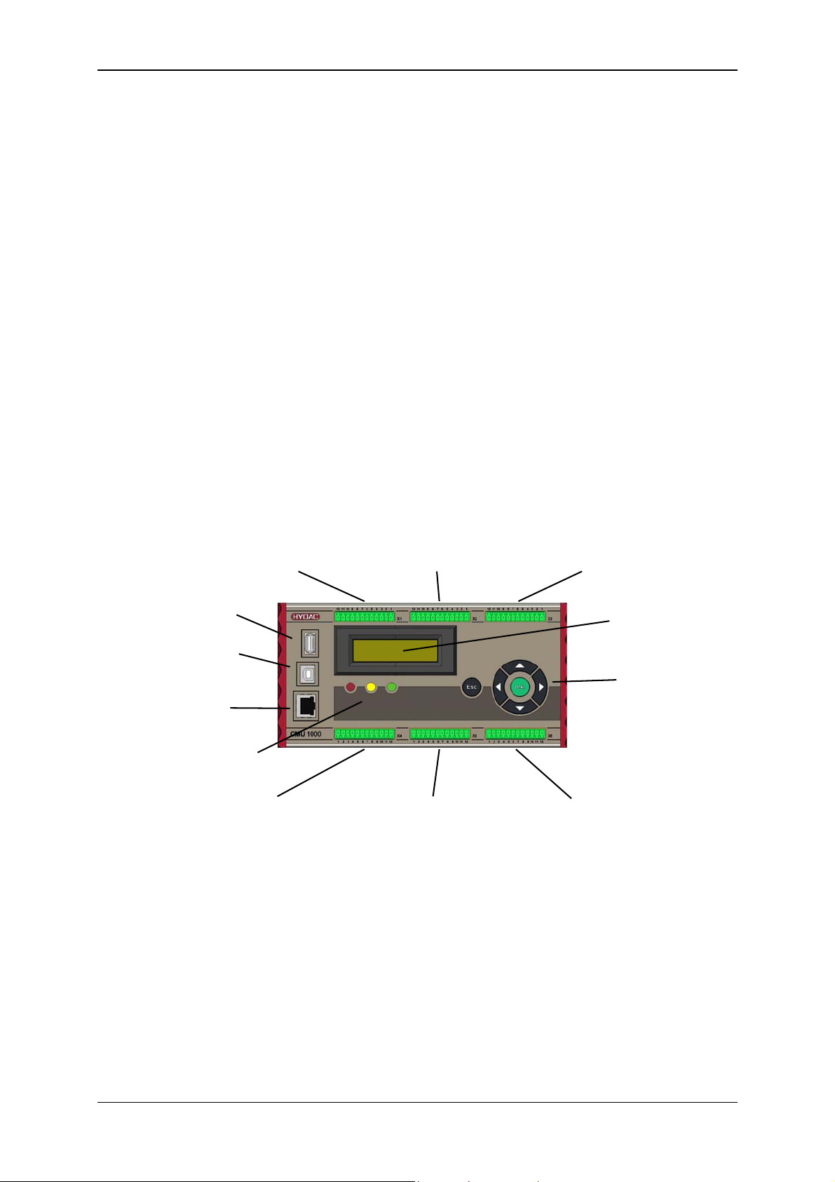
3.2 Control Elements/Connections
X1 X2 X3
HSI-channel A, B, C HSI-channel D, E, F HSI-channel G, H
Analog IN I, J, K Analog IN L, M, N Analog IN O, P and ± 10V L, P
with power supply with power supply with power supply
USB Master
(for MSD) LCD display
USB Slave
(PC connection)
Keypad
Ethernet
Status LEDs
X4 X5 X6
CAN, Frequency IN Q, R, Power supply. 24V 4x Relay OUT
Digital IN, Analog OUT RS232, HSI-Master, (changer)
IO-Link
Revised 17.12.2009 HYDAC ELECTRONIC GMBH Mat.-No.: 669749
Page 14
Condition Monitoring Unit CMU 1000 Page 14
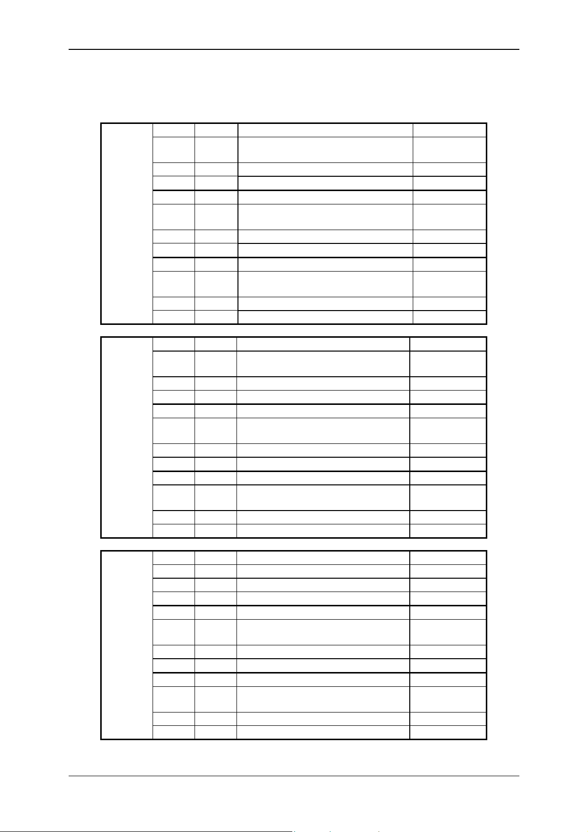
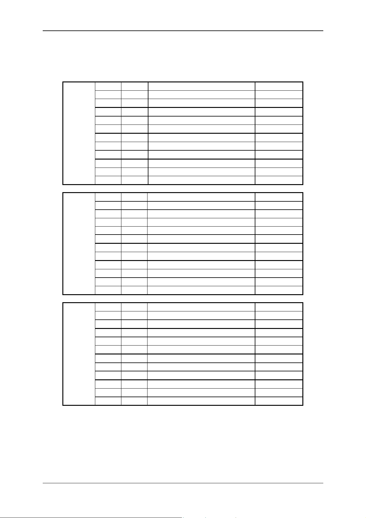
3.3 Terminal Allocations
Plugs Pin Channel Function I/O
1
2
3
4
5
6
K
C
J
B
X1
7
8
9
10
11
12
1
2
I
A
Analog input N IN
N
HSI Channel F /
F
Sensor recognition input N
3
4
5
6
X2
7
8
9
10
GND
Power supply
Analog input M IN
M
HSI Channel E /
E
Sensor recognition input M
GND
Power supply
Analog input L IN
L
HSI Channel D /
D
Sensor recognition input L
11
12
1
2
3
4
5
6
X3
7
8
9
10
GND
Power supply
+/-10V, Channel L IN
L
GND +/-10V
+/-10V, Channel P IN
P
GND +/-10V
Analog input P IN
P
HSI Channel H /
H
Sensor recognition input P
GND
Power supply
Analog input O IN
O
HSI Channel G /
G
Sensor recognition input O
11
12
GND
Power supply
Analog input K IN
HSI Channel C /
Sensor recognition input K
GND
Power supply
Analog input J IN
HSI Channel B /
Sensor recognition input J
GND
Power supply
Analog input I IN
HSI Channel A /
Sensor recognition input I
GND
Power supply
IN / OUT
IN / OUT
IN / OUT
IN / OUT
IN / OUT
IN / OUT
IN / OUT
IN / OUT
Revised 17.12.2009 HYDAC ELECTRONIC GMBH Mat.-No.: 669749
Page 15
Condition Monitoring Unit CMU 1000 Page 15
Plugs Pin Channel Function I/O
1
2
3
CAN
CAN
GND
4
5
X4
6
7
8
9
10
11
12
1
2
3
4
5
X5
6
7
8
9
10
11
12
GND
DI 1
DI 2
GND
AO 1
AO 2
GND
HSI
RS232
RS232
IO-Link
IO-Link
GND
+U
+U
0 V DC
0 V DC
0 V DC
0 V DC
1
2
DO 1
3
4
X6
5
6
7
8
DO 2
DO 3
9
10
11
DO 4
12
CAN Bus Low IN / OUT
CAN Bus High IN / OUT
CAN GND
Frequency input Q IN
Q
Frequency input R IN
R
GND
Digital In 1 IN
Digital In 2 IN
GND
Analoge out 1 OUT
Analoge out 2 OUT
GND Analoge out
HSI Master IN / OUT
RS232 OUT
RS232 IN
Power supply IO-Link IN
IO-Link communication IN / OUT
GND HSI / RS232 / IO-Link
Power supply +U
B
Power supply +U
B
B
B
Power supply 0 V DC
Power supply 0 V DC
Power supply 0 V DC
Power supply 0 V DC
Relay 1 NC
Relay 1 COM
Relay 1 NO
Relay 2 NC
Relay 2 COM
Relay 2 NO
Relay 3 NC
Relay 3 COM
Relay 3 NO
Relay 4 NC
Relay 4 COM
Relay 4 NO
Revised 17.12.2009 HYDAC ELECTRONIC GMBH Mat.-No.: 669749
Page 16
Condition Monitoring Unit CMU 1000 Page 16
A
A
A
A
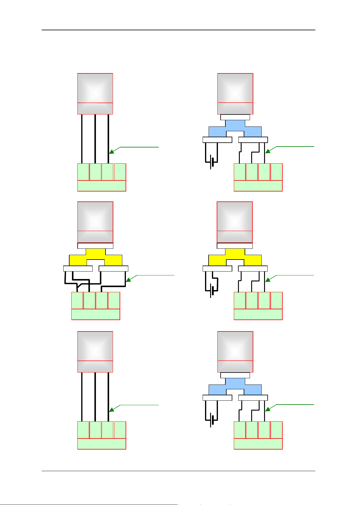
3.4 Examples of Connections
3.4.1 SMART sensors
HLB 1000
+UB GND HSI
1 2 3 4 5
12
11
10
+U
GND
B
HSI
A
- X 1
Sensor recognition
+ Signal
9
Ana.
I
1 2 3 4 5 1 2 3 4 5
External power
supply:
10..36 V DC
HLB 1000
+UB GND HSI
1 2 3 4 5
1 2 3 4 5
ZBE 26
B
12
11
+U
GND
B
10
HSI
- X 1
Sensor recognition
+ signal
9
Ana.
A
I
CS 1000
+UB GND HSI
1 2 3 4 5 6 7
1 2 3 4 5 6 7
ZBE 41
B
1 2 3 4 5 1 2 3 4 5 6 7 8
Sensor recognition
+ signal
CS 1000
+UB GND HSI
1 2 3 4 5 6 7
1 2 3 4 5 6 7
ZBE 41
B
1 2 3 4 5 1 2 3 4 5 6 7 8
Sensor recognition
+ signal
8
+U
7
GND 6 HSI
B
- X 1
5
Ana.
B
J
External power
supply:
10..36 V DC
8
+U
7
GND 6 HSI
B
- X 1
5
Ana.
B
J
AS 1000
+UB GND HSI
1 2 3 4 5
4
3
+U
GND 2 HSI
B
C
- X 1
Sensor recognition
+ Signal
1
Ana.
K
1 2 3 4 5 1 2 3 4 5
External power
supply:
10..36 V DC
AS 1000
+UB GND HSI
1 2 3 4 5
1 2 3 4 5
ZBE 26
B
4
3
+U
GND 2 HSI
B
- X 1
Sensor recognition
+ signal
1
Ana.
C
K
Revised 17.12.2009 HYDAC ELECTRONIC GMBH Mat.-No.: 669749
Page 17
Condition Monitoring Unit CMU 1000 Page 17
A
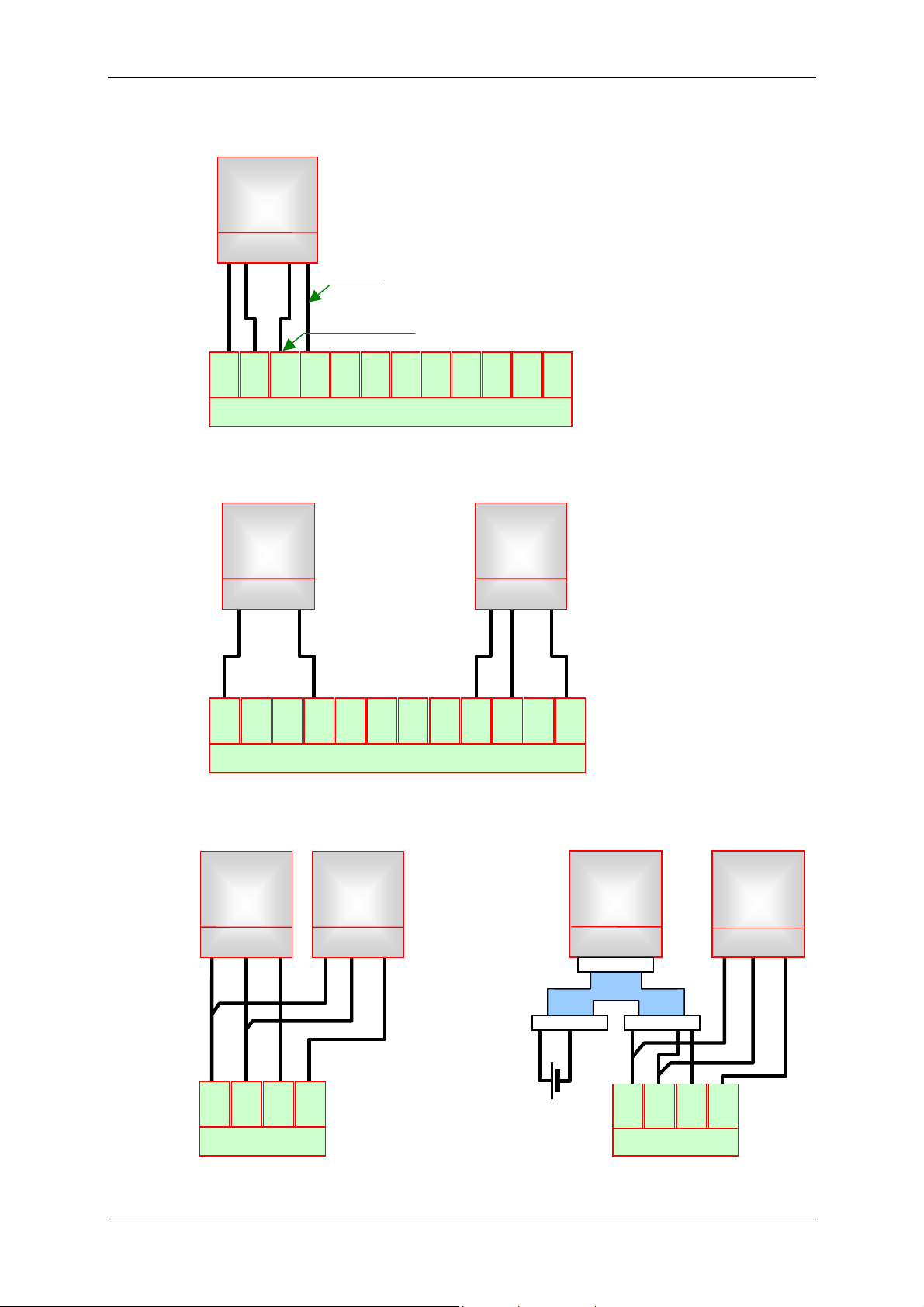
3.4.2 Standard HSI Sensors
HDA xxxx-H
ETS xxxx-H
EVS xxxx-H
+UB Gnd Adr HSI Sig
12
+U
1 4 2 5 3
11
10
GND
HSI
B
A
Signal
Sensor recognition
9
8
7
Ana.
+U
GND6 HSI
B
I
5
4
+U
3
GND2 HSI
B
Ana.
B
J
1
Ana.
C
K
- X 1
3.4.3 Standard Analog Sensors
5
J
HDA xxxx
ETS xxxx
EVS xxxx
ENS xxxx
Three-wire line
GND Signal
+U
B
4
3
+U
GND2 HSI
B
1
Ana.
C
K
HDA xxxx
ETS xxxx
EVS xxxx
ENS xxxx
Two-wire line
Signal + Signal -
12
11
10
+U
GND
B
HSI
9
8
7
Ana.
A
+U
GND6 HSI
B
I
Ana.
B
-X 1
3.4.4 SMART Sensors and Standard Analog Sensors
HLB 1000
CS 1000
AS 1000
+UB GND HSI
1 2 3 4 5
HDA xxxx
ETS xxxx
EVS xxxx
ENS xxxx
Three-wire line
GND Signal
+U
B
HLB 1000
+UB GND HSI
1 2 3 4 5
1 2 3 4 5
ZBE 26
B
1 2 3 4 5 1 2 3 4 5
HDA xxxx
ETS xxxx
EVS xxxx
ENS xxxx
Three-wire line
GND Signal
+U
B
12
11
10
+U
B
GND
- X 1
HSI
A
9
Ana.
I
External power
supply:
10..36 V DC
+U
12
B
11
GND
- X 1
10
HSI
A
9
Ana.
I
Revised 17.12.2009 HYDAC ELECTRONIC GMBH Mat.-No.: 669749
Page 18
Condition Monitoring Unit CMU 1000 Page 18
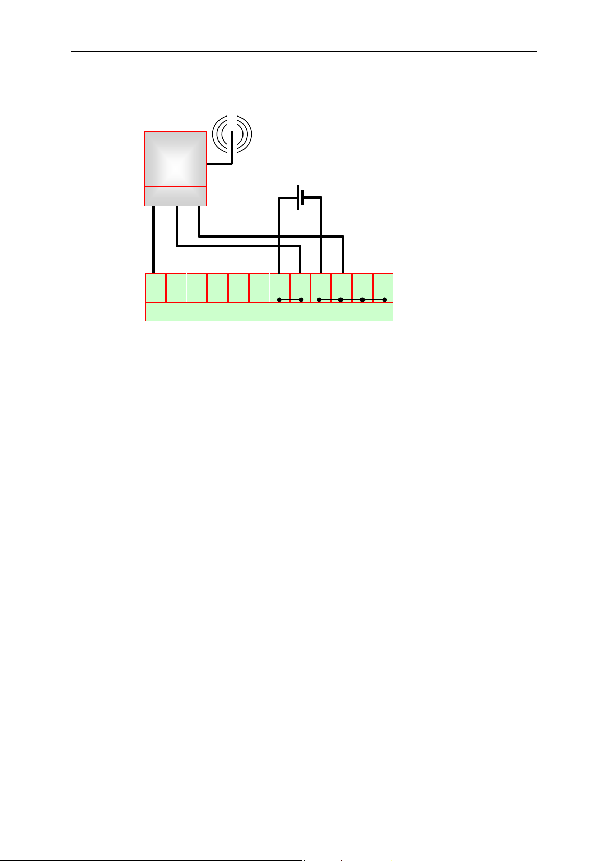
3.4.5 GSM Module CSI-F-10
CSI-F-10
HSI +UB GND
5 4 1 2 3
1
2
3
HSI
RS232
Master
TxD
RS232
RxD
4
IOLink
L+
IOLink
C/Q
18..35 V DC / 3,5 A
5
6
IOLink
GND
-X 5
7
VDC
IN
8
VDC
IN
9
VDC
GND
10
VDC
GND
11
VDC
GND
12
VDC
GND
Revised 17.12.2009 HYDAC ELECTRONIC GMBH Mat.-No.: 669749
Page 19
Condition Monitoring Unit CMU 1000 Page 19
4 Installation and Initial Operation
4.1 Installation Guidelines
We recommend the installation of the CMU 1000 in a control cabinet or switchbox. It
can be mounted on a standard top hat rail either horizontally or vertically.
Caution!
Keep the CMU 1000 devices well away from heat, high voltage and electrical
interference from other consumers!
When planning the installation space of the CMU 1000 in your control cabinet, take into
account any heat-generating devices present there and reserve cooler areas of the
control cabinet for the CMU 1000.
If an electronic device is operated in a high ambient temperature, then this reduces the
time interval between breakdowns.
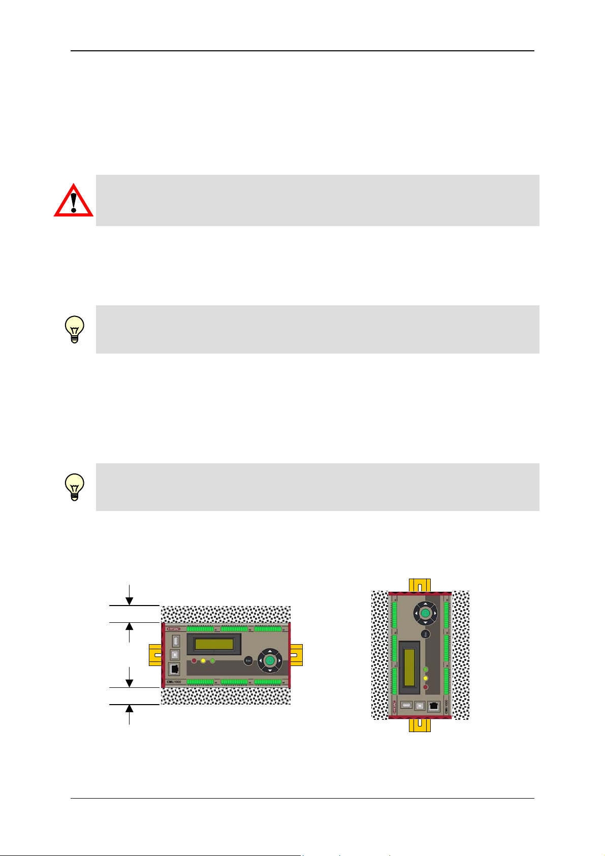
Note!
Allow sufficient clearance between the CMU 1000 and other devices for cooling and
wire placement!
The CMU 1000 devices are designed for natural heat dissipation by means of
convection. For that reason, allow at least 25 mm of open space both above and below
the devices in order to ensure heat dissipation. Also ensure a minimum installation
depth of 75 mm.
If the ambient temperature nonetheless still exceeds the maximum authorized
operating temperature of the device, then a system providing sufficient cooling (e.g.
control cabinet air-conditioning) must be provided for.
Note!
If the CMU 1000 is installed in vertical position, then the maximum permissible ambient
temperature is reduced by 10°C!
When planning the layout for your system, leave sufficient clearance around the device
both above and below between it and all other devices to allow for the wiring the
peripherals and connecting of the communications cable.
min. 25 mm
min. 25 mm
Revised 17.12.2009 HYDAC ELECTRONIC GMBH Mat.-No.: 669749
Page 20
Condition Monitoring Unit CMU 1000 Page 20
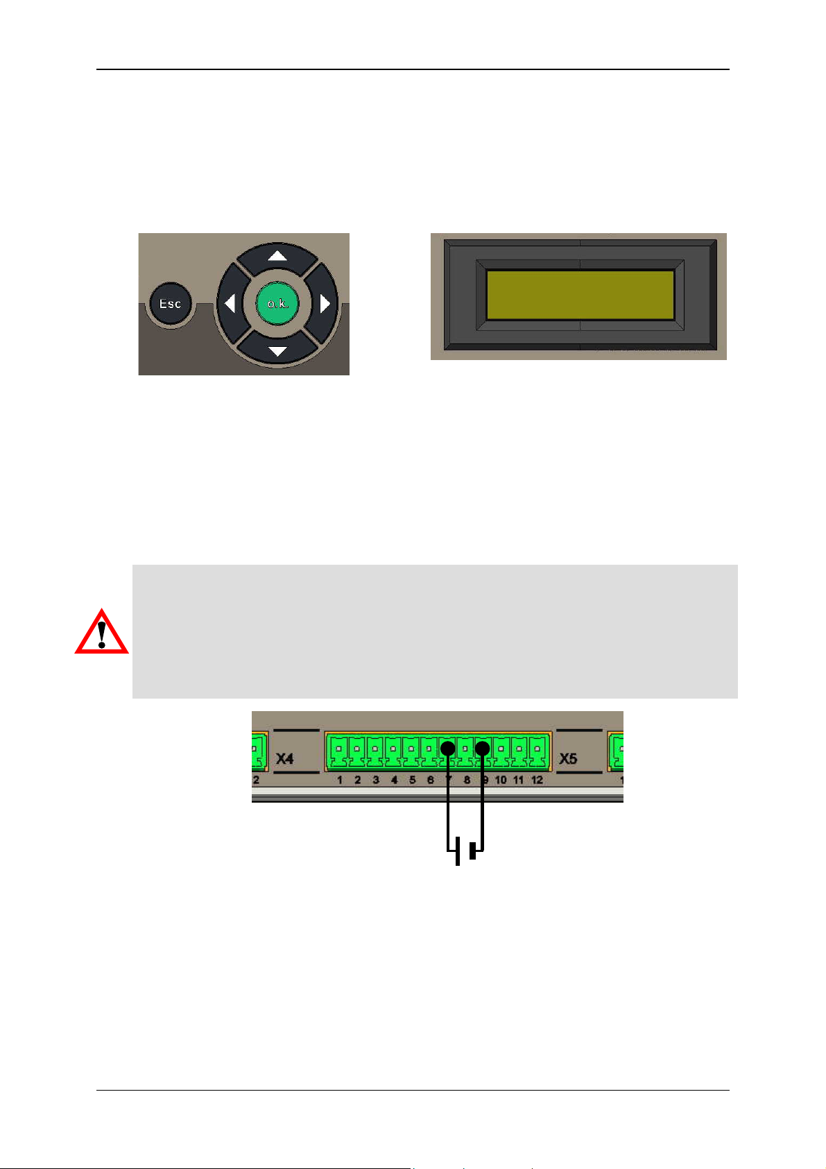
4.2 Control Element on the Device
The following control element is available on the device for operating the CMU 1000
and performing the basic settings:
Keypad LCD display
4.3 Power Supply Connection
Before installing or removing an electrical device, you must make sure that the voltage
supply to the devices is switched off. Implement all of the necessary safety precautions
and make sure that the voltage supply to the CMU 1000 is switched off before
installation/removal.
Warning!
If you attempt to install or to wire the CMU 1000 and/or connected accessory
components while it or they are switched on, this could lead to an electrical shock
and/or to device malfunction. Implement all of the necessary safety precautions and
make sure that the voltage supply to the CMU 1000 and/or to connected accessory
components is switched off prior to installation/removal.
+ -
18 .. 35 V DC
Revised 17.12.2009 HYDAC ELECTRONIC GMBH Mat.-No.: 669749
Page 21
Condition Monitoring Unit CMU 1000 Page 21
4.4 Behavior when Switching On/Restart
The CMU 1000 is not equipped with a power switch. The behavior of the device
following switch-on depends on whether or not a CM Program has been stored in the
device memory.
4.4.1 No CM Program Available in the Device
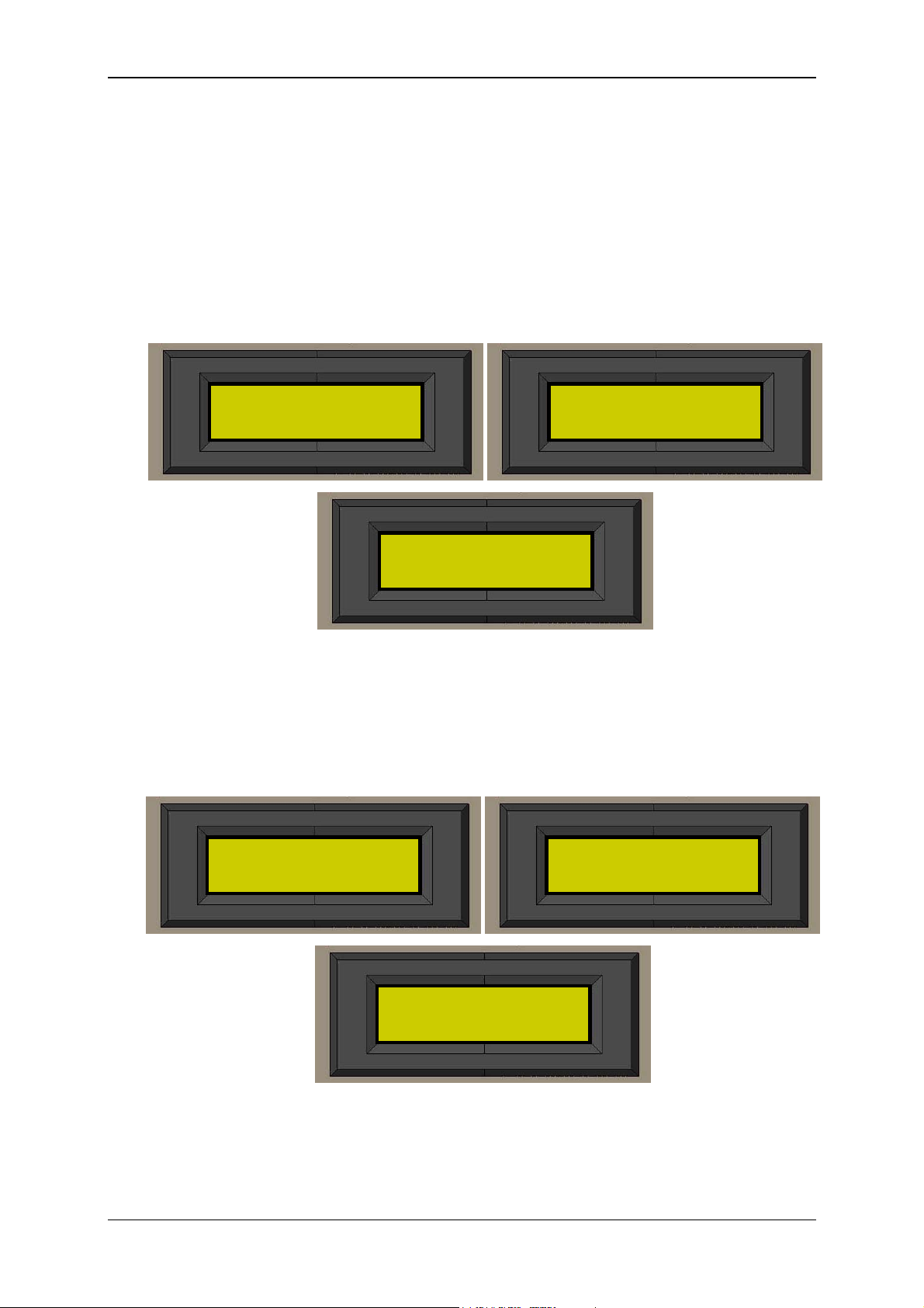
If the CMU 1000 is still in the condition it was at the time of delivery, and if no
application program has yet been loaded into the CMU, then the following displays will
appear in sequence in the LCD display:
HHyyddaacc EElleeccttrroonniicc
CCMMUU11000000 VVxxxx..yyyy
NNoo
RReessuulltt VVaalluueess
SSeennssoorr CChheecckk
........
4.4.2 CM Program Available in the Device
If an application program is stored in the CMU, then this will restart. The sensor
configuration and the sensor constellation will also be checked at this time.
The following displays appear in sequence:
HHyyddaacc EElleeccttrroonniicc
CCMMUU11000000 VVxxxx..yyyy
Revised 17.12.2009 HYDAC ELECTRONIC GMBH Mat.-No.: 669749
>>PPrrooggrraamm nnaamme
LLooaaddeedd
SSeennssoorr CChheecckk
........
e
<<
Page 22

Condition Monitoring Unit CMU 1000 Page 22
If one or more output values are programmed in the CM Program that is loaded, (see
Chap. 7.9.1 and 7.9.2), then the display will jump to the first output value after startup.
When several output values have been programmed, you can switch between the
individual program values with the ▲ and ▼ key.
Example:
OOiill tteemmpp.. ttaannk
3311..22°°CC
▲ ▼
k
WWoorrkkiinngg pprreessssuurre
2277 bbaarrss
Note!
No conditions are registered or saved in the device after switch-off. Exceptions to this
are the input parameters (settings), which the user has defined and saved in the menu.
e
Revised 17.12.2009 HYDAC ELECTRONIC GMBH Mat.-No.: 669749
Page 23
Condition Monitoring Unit CMU 1000 Page 23
5 Basic Settings/Menu Structure
The CMU 1000 configuration and settings can be carried out in two different modes:
5.1 Configuration on the Device
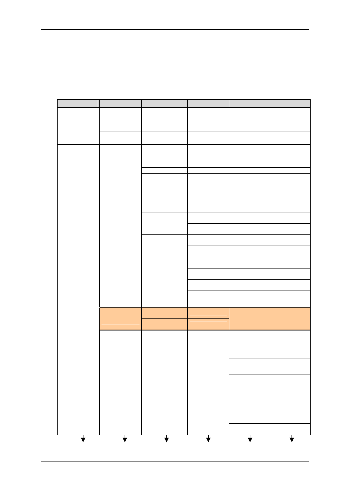
5.1.1 Menu Structure for Operation on the Device
Level 1 Level 2 Level 3 Level 4 Level 5 Level 6
Input values
Settings
Sensor A
Sensor B
:
:
Sensor R
Basic settings
CM Program
settings
Peripherals
[Display of current
measured value]
[Display of current
measured value]
[Display of current
measured value]
Name [Enter name]
Language
Port RS 232 / HSI
Dateformat
Recording settings
HLB reset
Time settings
Network settings
Numerical input
values
Boolean input
values
Channel settings
German
English
French
TT.MM.JJ
MM/TT/JJ
JJ-MM-TT
Delete record
Continue record
HLB reset
Sensor
Date
Time
IP-Address
Subnetmask
Gateway
MAC-Address
[Enter value]
Yes / No
Channel A
:
Channel H
Channel I
:
Channel P
Yes /
No
Yes /
No
Yes /
No
Sensor A …
Sensor H
[Enter
current date]
[Enter
current time]
[enter
IP address]
[enter
subnetmask]
[enter
Gateway address]
[MAC address
is permanently
set at the factory]
The menu option appears only if one
or more input functions are used in
the CM Program!
Name
Name
Mode
Input signal
Low
range
[Enter
name]
[Enter
name]
Automatic
Off
Manual
HSI
0 .. 20 mA
4 .. 20 mA
0 .. 5 V
0 .. 10 V
0,5 .. 4,5 V
0,5 .. 5,5 V
1 .. 5 V
1 .. 6 V
[Enter
value]
Revised 17.12.2009 HYDAC ELECTRONIC GMBH Mat.-No.: 669749
Page 24
Condition Monitoring Unit CMU 1000 Page 24
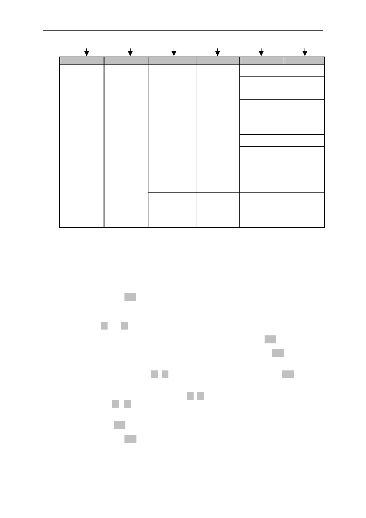
Level 1 Level 2 Level 3 Level 4 Level 5 Level 6
Settings
Peripherals
Channel settings
PWM settings
(analog outputs)
Channel I
:
Channel P
Channel Q
:
Channel R
PWM 1
(analog output 1)
PWM 2
(analog output 2)
High
range
Decimal
format
Unit (of
measurement)
Name
Mode
High
range
Factor
Decimal
format
Unit (of
measurement)
0 to 20 mA
4 to 20 mA
0 to 10 V
0 to 20 mA
4 to 20 mA
0 to 10 V
[Enter
value]
0
0.0
0.00
0.00
[Enter
unit]
[Enter
name]
Off
Active
[Enter
value]
[Enter
value]
0
0.0
0.00
0.00
[Enter
unit]
5.1.2 Key Functions during Operation on the Device
The setting parameters and displays listed in the previously shown menu structure can
be called up and the corresponding settings and selections can be made with the key
pad.
Pressing the o.k. key once takes you out of the measured value display and
into the CMU 1000 menu. .
You can switch between the individual menu options of a level by pressing the
keys ▲ or ▼ .
The next-lower menu level can be accessed by pressing the o.k. key once.
You can go back to the next-higher menu level by pressing the Esc key once.
The selection of the specific setting values (e.g. interface, date format, mode,...)
can be made with the ▲ ▼ keys and confirmed by pressing the o.k. key.
To enter name, date and time values, addresses measurement ranges, etc.,
select the cursor position with the ◄ ► keys.
Use the ▲ ▼ keys to select the required uppercase and lowercase letters,
numbers and special characters.
Press the o.k. key to confirm the completed entry.
Pressing the Esc key aborts the entry without applying the changes.
Revised 17.12.2009 HYDAC ELECTRONIC GMBH Mat.-No.: 669749
Page 25
Condition Monitoring Unit CMU 1000 Page 25
5.2 Configuration Using CMWIN PC Software
The configuration of the CMU 1000 and the carrying out of the basic settings can also
be performed from a PC with the "CM Manager".
The "CM Manager" is a component part of the CMWIN HYDAC PC software, starting
with Version 3, and provides you with various tools and functions for the connecting,
configuring, parameterizing and reading-out of CM devices.
The following options are available for setting up the connection with the CMU 1000:
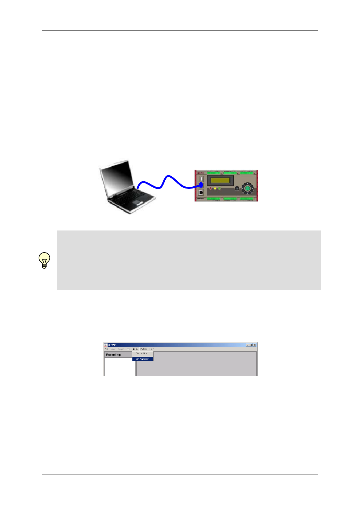
5.2.1 Direct Connection
• First connect your PC with the USB slave port on the CMU 1000
USB
Note!
If the CMU 1000 is being connected for the first time with the PC via USB, then you
must first install the HYDAC USB driver „HE-Virtual-Comport-Driver“.
The driver are included on the CD-ROM contained in the scope of delivery.
• Call up the file “HE-V
OMPORT-DRIVER” folder and follow the instructions of the “Setup Wizard”.
C
IRTUAL-COMPORT-INSTALLER.EXE” in the “HE-VIRTUAL-
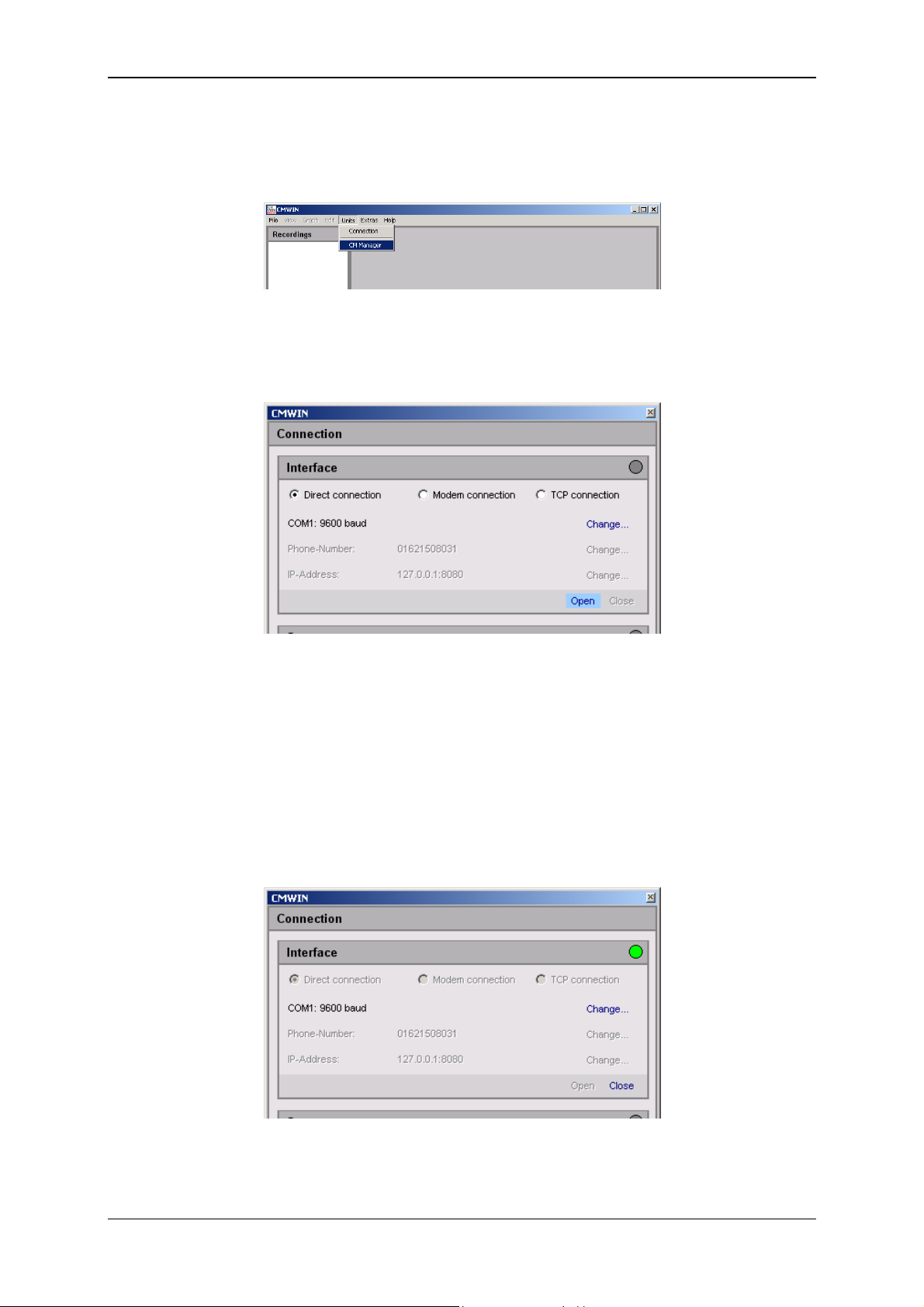
• Start the HYDAC PC software CMWIN
• In the Units Menu, select the "CM Manager" option.
• If the Connection window does not open automatically, select
"Connection" in the menu bar of the CM Manager.
Revised 17.12.2009 HYDAC ELECTRONIC GMBH Mat.-No.: 669749
Page 26
Condition Monitoring Unit CMU 1000 Page 26
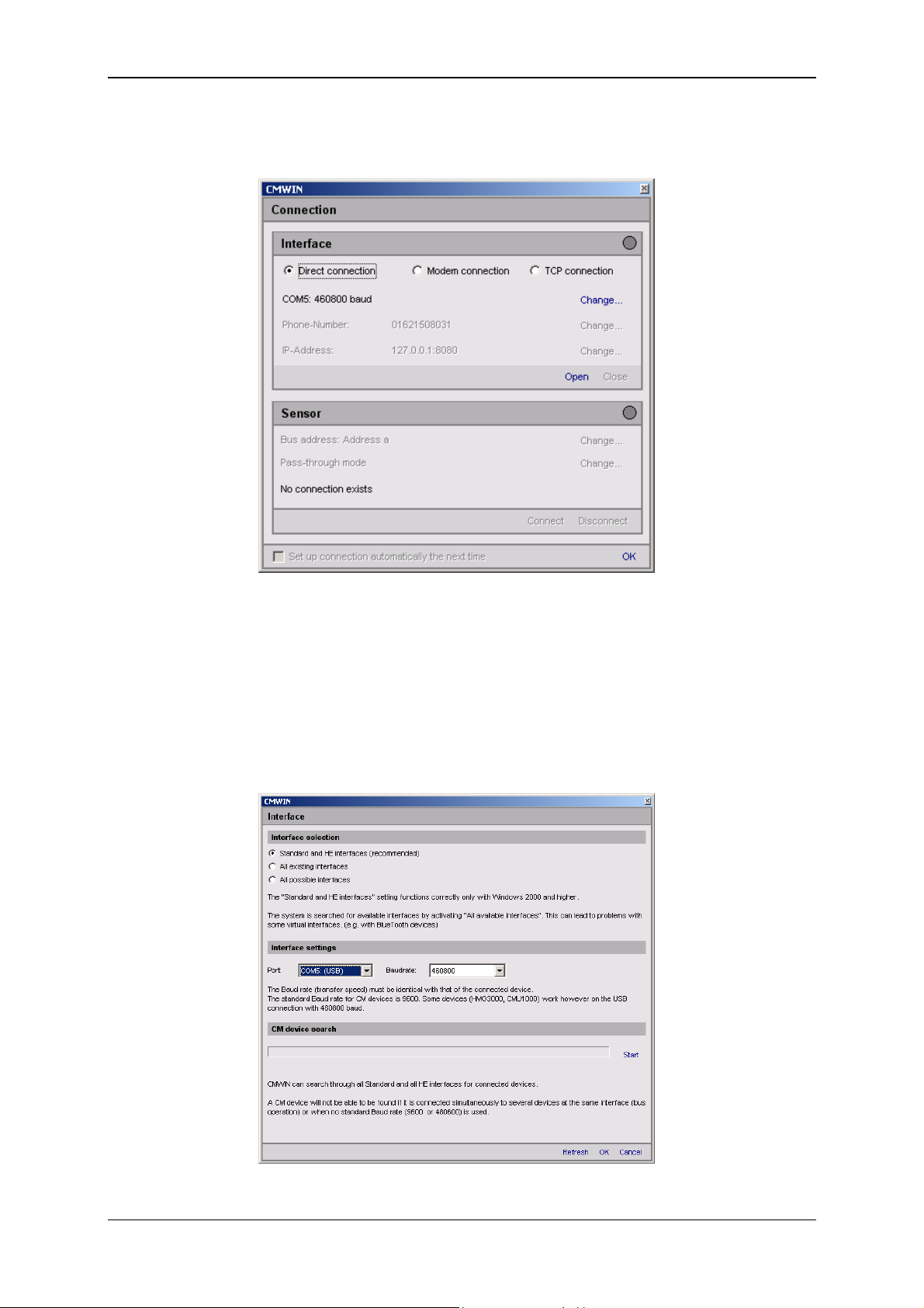
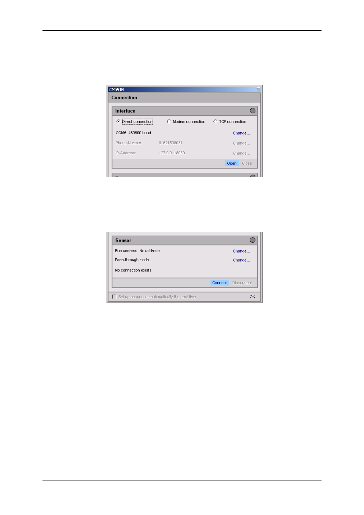
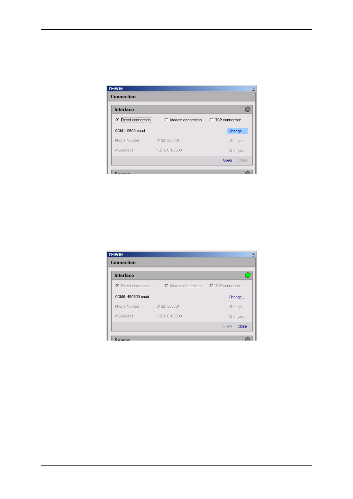
• Mark the option "Direct Connection" option in the window that opens.
• Click on "Change" to open the window for the interface settings.
• Make the corresponding preselection for the port settings in the window that
opens under Interface selection.
• Select the respective port address and Baud rate under Interface settings.
• As an alternative, you can also search automatically under CM device search
for CM devices connected to the PC by pressing "Start".
• Pressing "Refresh" causes the interfaces marked under Interface selection to
be refreshed in terms of availability.
• Click on “OK“ to apply the modified settings or “Cancel“ to discard these
changes. In either case you will then return to the Connection window.
Revised 17.12.2009 HYDAC ELECTRONIC GMBH Mat.-No.: 669749
Page 27
Condition Monitoring Unit CMU 1000 Page 27
• In the Interface field, select the option "Open" in order to open the selected
interface (COM port).
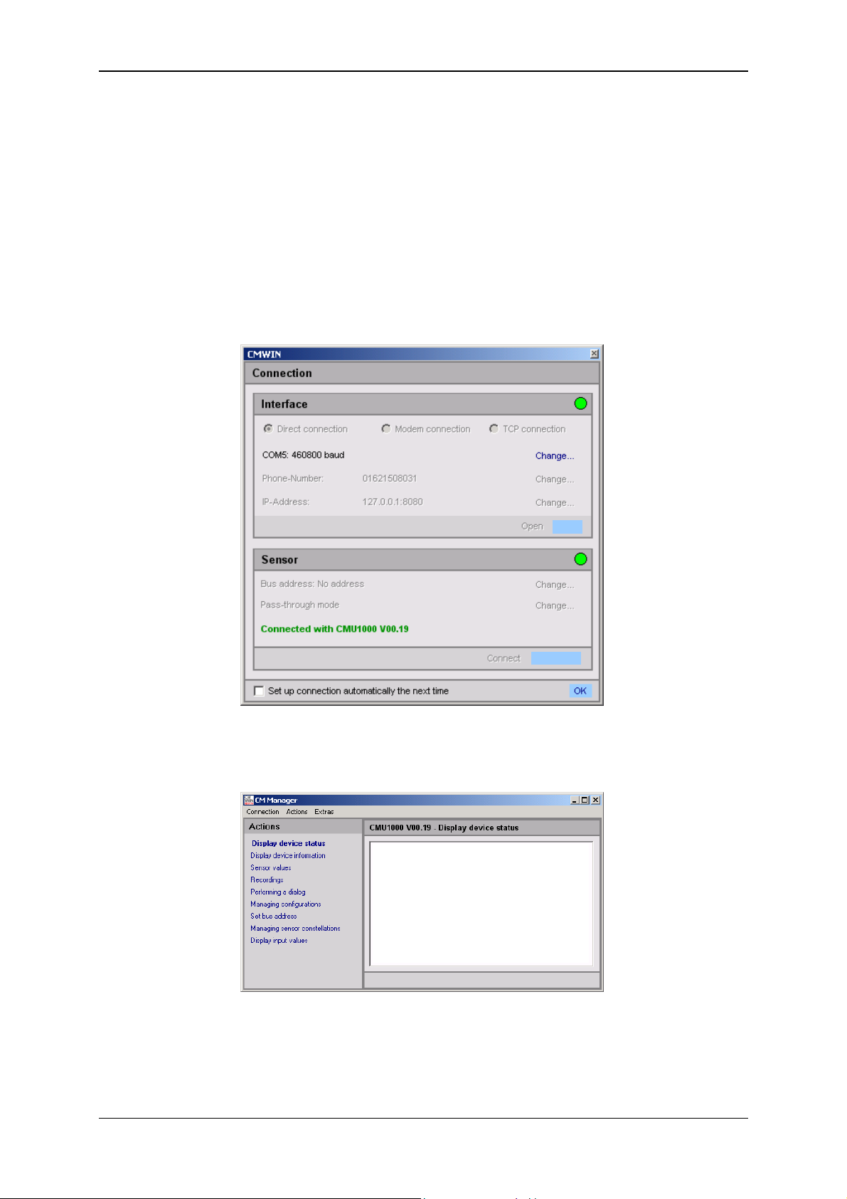
The opened interface will be symbolized by a green dot on the right-hand edge
of the window.
• Afterwards click on "Connect" in the Sensor field to connect the CMU 1000 to
the PC.
The successful connection will be symbolized by a green dot on the right-hand
edge of the window.
Revised 17.12.2009 HYDAC ELECTRONIC GMBH Mat.-No.: 669749
Page 28
Condition Monitoring Unit CMU 1000 Page 28
• Pressing "Disconnect" in the Device field allows you to interrupt the existing
connection between the CMU 1000 and the PC.
• The interface (COM port) used can be closed again on the PC by pressing
"Close" in the Interface field.
• At the end you also have the option of selecting an automatic connection setup.
Placing a checkmark in the box for "Set up connection automatically next
time " causes the CMWIN software to set up a connection automatically with
the CMU 1000 that is linked via USB during startup. To ensure that this
happens, no changes should be made to the interface parameter settings after
the currently existing connection is disconnected.
• Click on "OK" to complete the connection setup and to
return to the CM Manager.
• The following window opens after the connection has been successfully
established:
The menu structure and window properties of the CM Manager are explained below in
greater detail in Chapter 5.2.5 ff.
Revised 17.12.2009 HYDAC ELECTRONIC GMBH Mat.-No.: 669749
Page 29
Condition Monitoring Unit CMU 1000 Page 29
A
A
c
A
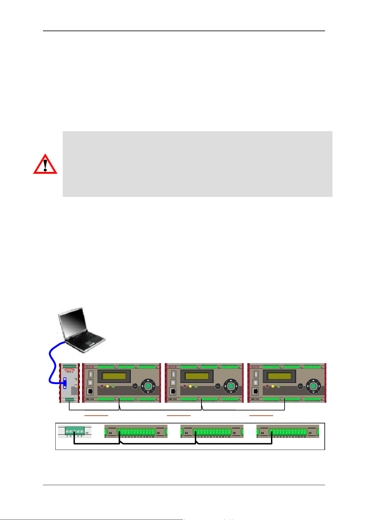
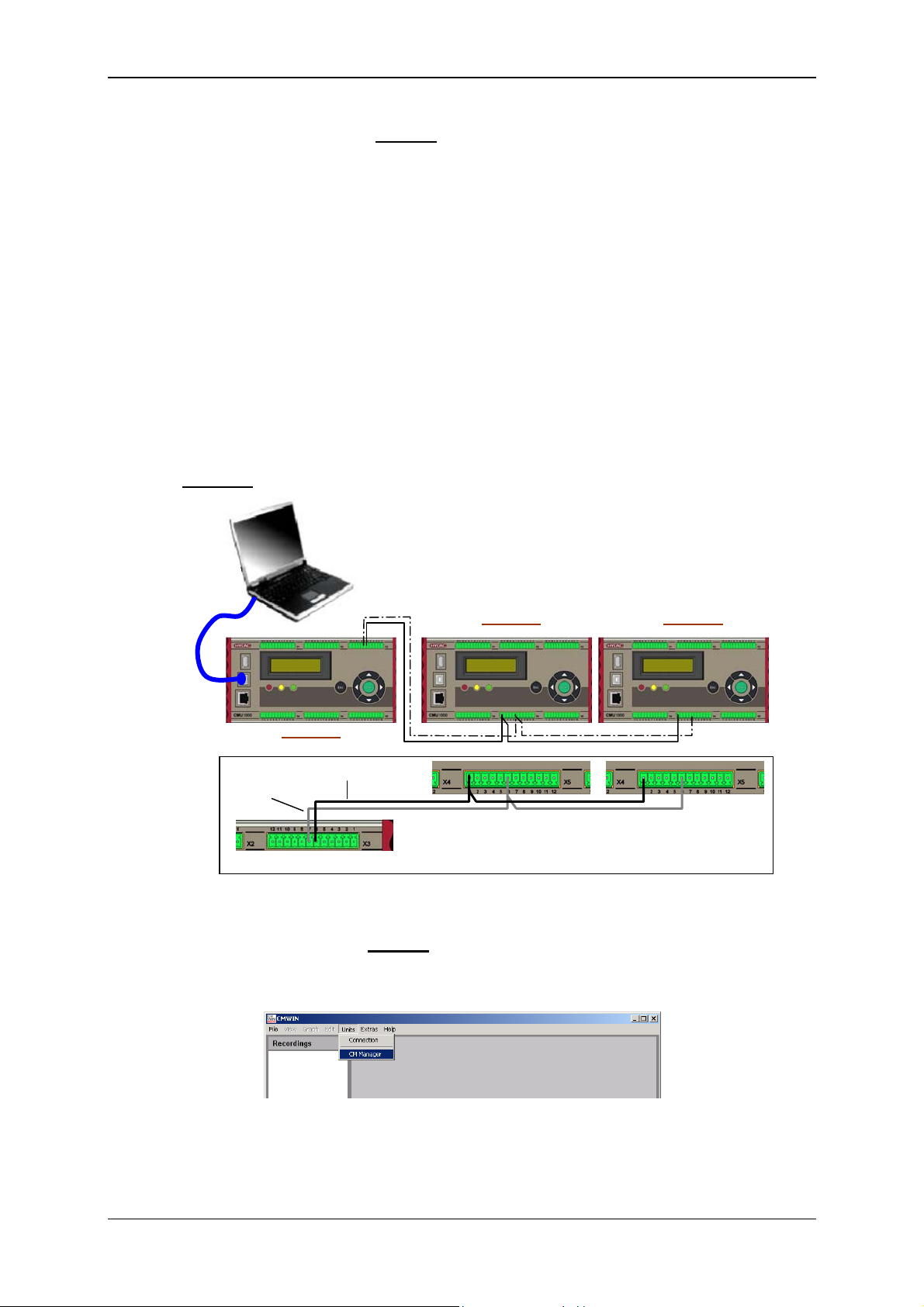
5.2.2 Direct Connection via HSI Bus
You can connect several HYDAC CM devices with one another (maximum of 26
devices) via the so-called "HSI Bus". Each CM device must be assigned an HSI
Bus address for this purpose (see Chap. 5.2.5.7).
This kind of bus setup is presented below, using as an example three CMU 1000
devices. Other HYDAC CM devices such as SMART sensors (e.g. HYDACLab
CS 1000) or CSI modules can however also be linked in random sequence and
configuration in one HSI Bus.
Caution!
If you connect devices with one another that do not have the same reference
voltage, this can cause unwanted currents in the HSI connection cable.
These unwanted currents can lead to communication errors or property damage in
the devices.
Make sure that all of the devices that you connect with one another via HSI Bus
either have the same reference wire in the electricity circuit or are electrically
disconnected, so that no unwanted currents can arise.
5.2.2.1 Device Connection via CSI-B-2 Interface Module
®
,
RS232 /
RS485
• Connect the serial interface of your PC (RS232 or RS485) with the 9-pin SUB-D
socket of the HYDAC interface module CSI-B-2 via a corresponding data cable
(interface module and data cable are not included in the scope of delivery for
the CMU 1000).
• Connect all of the devices via the "HSI Master" connection.
(-X2/Pin 3 on the CSI-B-2 and -X5/Pin 1 on the CMU 1000)
• Switch on the voltage supplies for all of the connected devices.
dresse a
dresse
dresse d
Revised 17.12.2009 HYDAC ELECTRONIC GMBH Mat.-No.: 669749
Page 30
Condition Monitoring Unit CMU 1000 Page 30
5.2.2.2 Connection Setup via CSI-B-2 Interface Module
• Start the HYDAC PC software CMWIN
• In the Units Menu, select the "CM Manager" option.
• If the Connection window does not open automatically, select
"Connection" in the menu bar of the CM Manager.
• Mark the option "Direct Connection" option in the window that opens.
• Click on "Change" to open the window for the interface settings.
• Make the corresponding preselection for the port settings in the window that
opens under Interface selection.
• Select the respective port address and Baud rate under Interface settings
(RS232 or RS485 with 9600 Baud).
• Pressing "Refresh" causes the interfaces marked under Interface selection to
be refreshed in terms of availability.
• Click on “OK“ to apply the modified settings or “Cancel“ to discard these
changes. In either case you will then return to the Connection window.
• Click on Open to open the selected interface. The opened interface is indicated
by a green dot on the upper right.
Revised 17.12.2009 HYDAC ELECTRONIC GMBH Mat.-No.: 669749
Page 31

Condition Monitoring Unit CMU 1000 Page 31
• Select Change in the Bus address line. The following window opens:
• Select the respective device address in the selection window (Address d in our
example).
• Confirm this with OK.
• Afterwards click on Connect to connect the PC to the CMU 1000 (Address d).
• The successful establishment of the connection will be signalled as shown
below:
• End the connection setup by confirming with OK.
Revised 17.12.2009 HYDAC ELECTRONIC GMBH Mat.-No.: 669749
Page 32
Condition Monitoring Unit CMU 1000 Page 32
A
A
c
A
5.2.2.3 Device Connection without CSI-B-2 Interface Module
As an alternative, you can also set up an HSI Bus without a CSI-B-2 interface
module and access the individual devices from the PC. For this you will need a
CMU 1000 for communications with the PC, which in such cases functions as an
"HSI Master".
• First establish which CMU 1000 is the "Master" for the HSI Bus, i.e. at which
CMU 1000 the PC will be connected.
The other CMU devices are connected to this device as "Slaves". Because of
the fact that the "Master" treats all of the other devices on the HSI Bus as
SMART sensors, the first "Slave" must be connected to one of the eight HSI
channels of the CMU 1000 (Channels A ... H) (see Chap. 3.3).
• Connect your PC via USB with the "Master" CMU 1000
• All "Slave devices" are connected via the "HSI Master" connection (-X5/Pin 1
and Pin 6) to the HSI Bus and linked with one another.
Example:
dresse a
HSI Master
HSI GND
Channel
dresse
5.2.2.4 Connection Setup without
CSI-B-2 Interface Module
• Start the HYDAC PC software CMWIN
• In the Units Menu, select the "CM Manager" option.
dresse d
Revised 17.12.2009 HYDAC ELECTRONIC GMBH Mat.-No.: 669749
Page 33
Condition Monitoring Unit CMU 1000 Page 33
• If the Connection window does not open automatically, select
"Connection" in the menu bar of the CM Manager.
• Mark the option "Direct Connection" option in the window that opens.
• Click on "Change" to open the window for the interface settings.
• Make the corresponding preselection for the port settings in the window that
opens under Interface selection.
• Select the respective port address and Baud rate under Interface settings
(USB with 460,800 Baud).
• Pressing "Refresh" causes the interfaces marked under Interface selection to
be refreshed in terms of availability.
• Click on “OK“ to apply the modified settings or “Cancel“ to discard these
changes. In either case you will then return to the Connection window.
• Click on Open to open the selected interface. The opened interface is indicated
by a green dot on the upper right.
• To set up a connection with the "Master" CMU, simply click on Connect and
then OK.
Revised 17.12.2009 HYDAC ELECTRONIC GMBH Mat.-No.: 669749
Page 34
Condition Monitoring Unit CMU 1000 Page 34
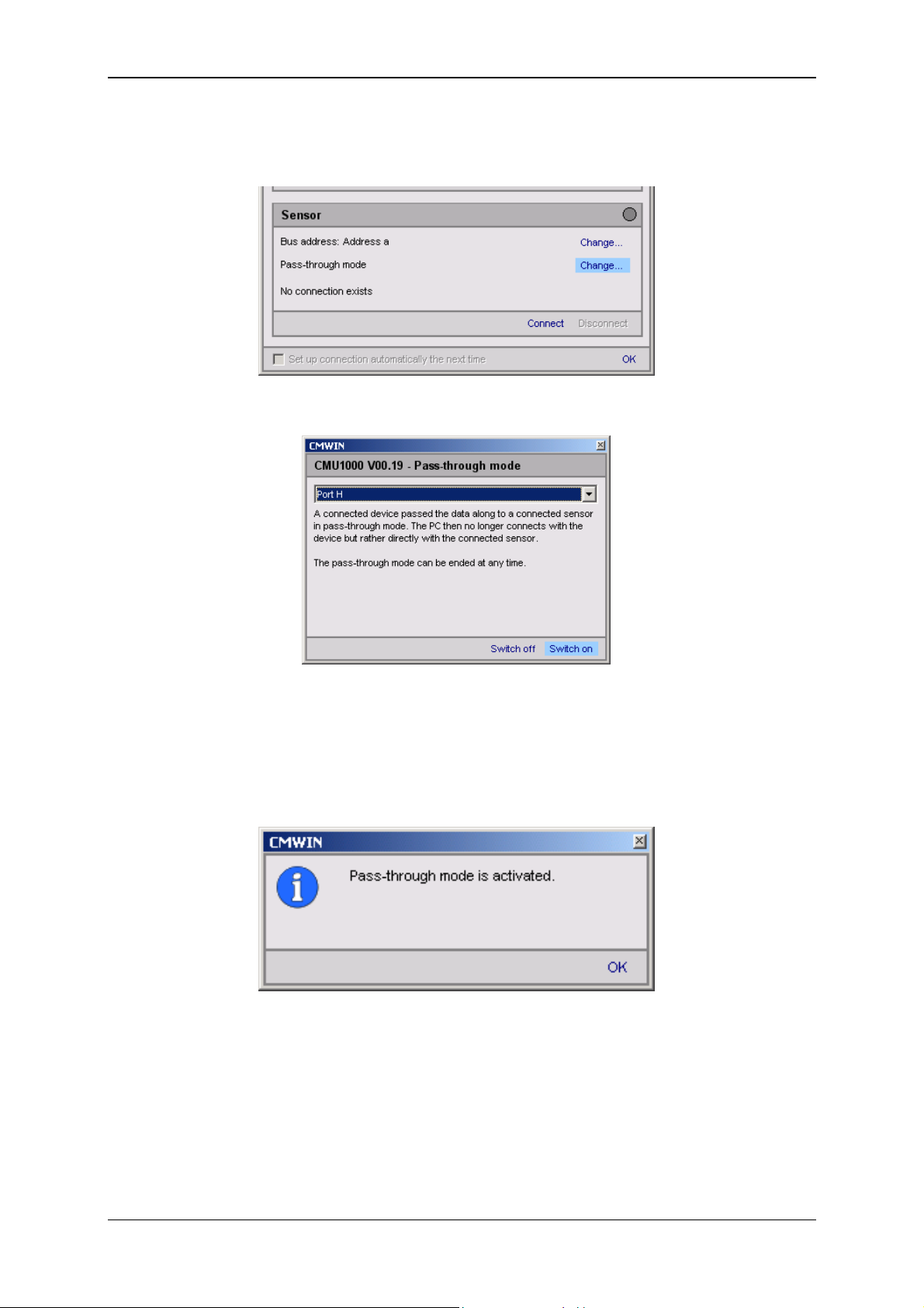
• To set up a connection with one "Slave" CMU (e.g. Address d), proceed as
follows:
• Select Change in the Pass-through mode line. The following window opens:
• Select the HSI channel in the selection window to which the slave devices are
connected (in our example, Port H at the "Master" CMU).
• Afterwards, click on Switch on in order to switch on the pass-through mode for
the selected channel.
• The following message appears:
• Confirm this with OK.
Revised 17.12.2009 HYDAC ELECTRONIC GMBH Mat.-No.: 669749
Page 35
Condition Monitoring Unit CMU 1000 Page 35
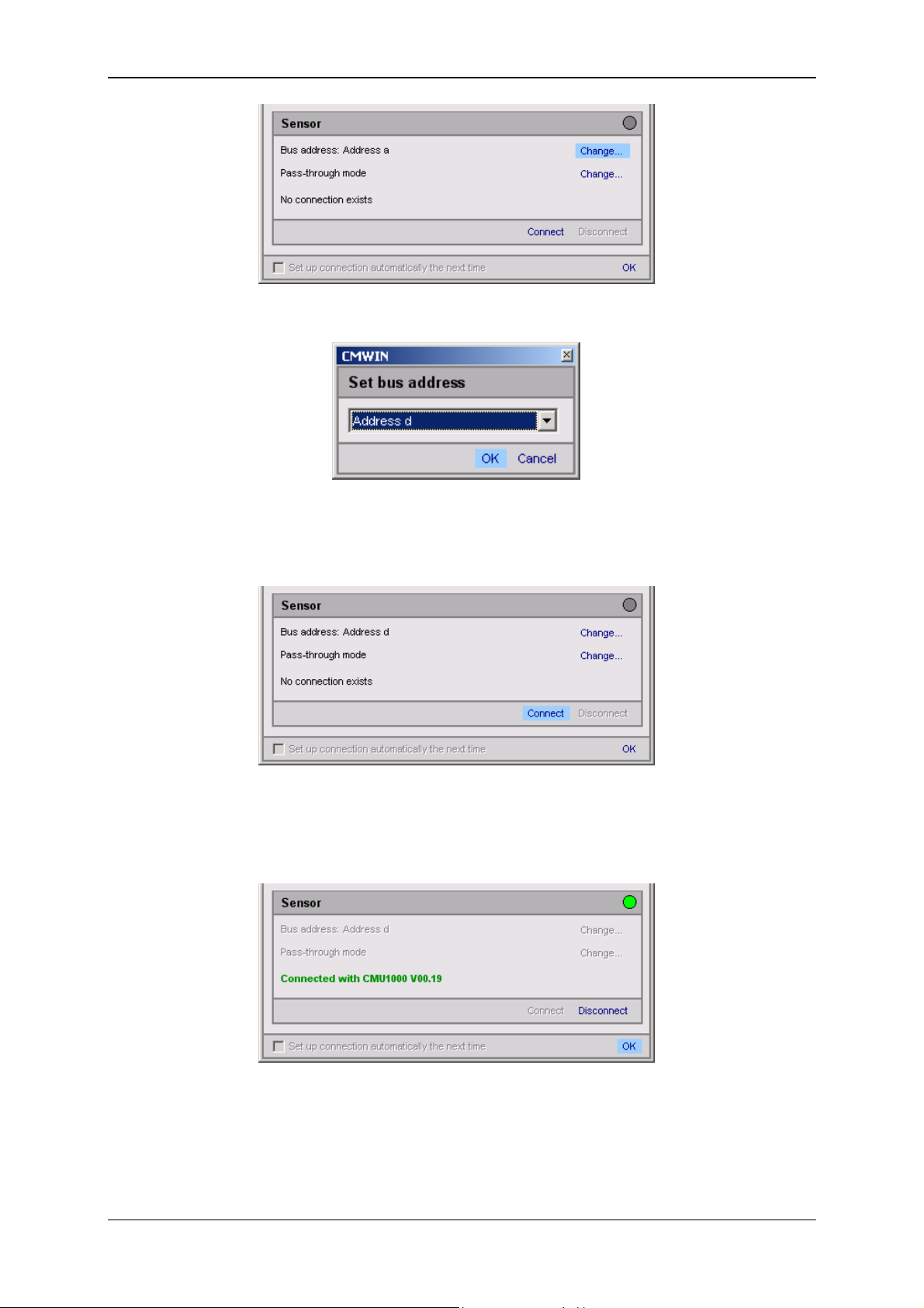
• Select Change in the Bus address line. The following window opens:
• Select the respective device address in the selection window
(Address d in our example).
• Confirm this with OK.
• Afterwards click on Connect to connect the PC to the Slave CMU (Address d).
• The successful establishment of the connection will be signalled as shown
below:
• End the connection setup by confirming with OK.
Revised 17.12.2009 HYDAC ELECTRONIC GMBH Mat.-No.: 669749
Page 36

Condition Monitoring Unit CMU 1000 Page 36
• The following message now appears in the Master CMU display:
PPaassss--tthhrroouugghh MMoodde
EESSCC ttoo FFiinniisshh
The message will remain in the display for as long as the "Master" CMU
continues to be operated in pass-through mode.
The pass-through mode can also be switched off on the CMU itself (instead of
by means of the Connection Menu in the CM Manager) by pressing the Esc key
on the device.
Note!
Error messages can occur if the pass-through mode is switched off at the "Master"
CMU (either via software or directly on the device), because the signals to the channel
to which the "Slave" devices are connected can no longer be evaluated under certain
circumstances.
e
Revised 17.12.2009 HYDAC ELECTRONIC GMBH Mat.-No.: 669749
Page 37
Condition Monitoring Unit CMU 1000 Page 37
5.2.3 Modem Connection
You also have the option of setting up a connection by means of the Standard GSM
mobile radio network.
In the following we present an example of this kind of communication link.
5.2.3.1 Device Connection/Pin Connections
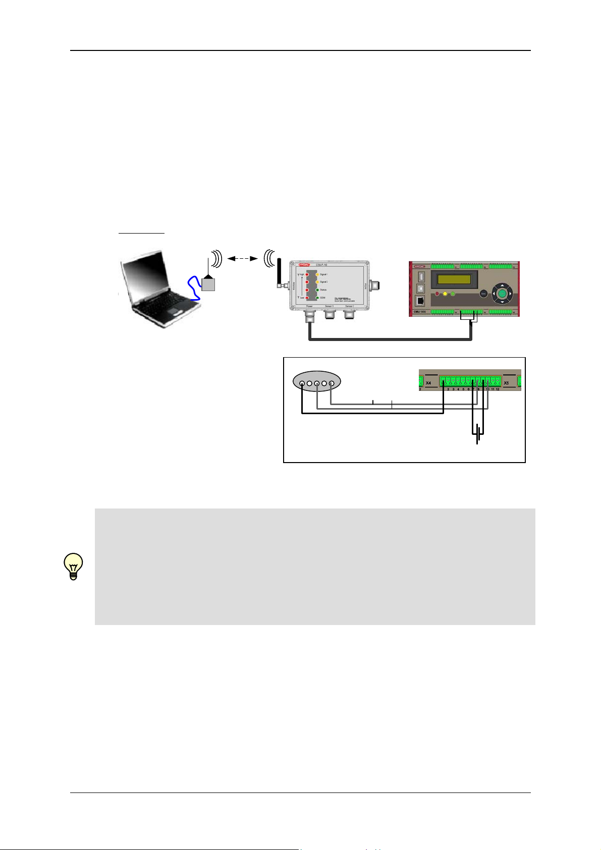
Connect a Standard GSM modem to your PC and connect the CMU 1000 to the
HYDAC GSM radio module CSI-F-10 in accordance with the diagram.
Example:
GSM
5 4 3 2 15
+U
GND
B
HSI
18..35 V DC / 5 A
Note!
In order to be able to communicate with the CMU 1000 via the connected CSI-F-10
GSM radio module, this must first be configured. This means that the mobile phone
numbers which are authorized for access must be stored in the CSI-F-10 and
appropriate permissions assigned.
To configure the GSM radio module CSI-F-10, or to make changes in a configured
device, first connect directly with the GSM radio module CSI-F-10 as described below.
Revised 17.12.2009 HYDAC ELECTRONIC GMBH Mat.-No.: 669749
Page 38
Condition Monitoring Unit CMU 1000 Page 38
5.2.3.2 Establishing Connection with GSM Radio Module CSI-F-10
• Connect the CMU 1000 for configuring the CSI-F-10 GSM radio module to your
PC as also described in Chapter 5.2.1 Direct Connection, Chapter 5.2.2 Direct
Connection via HSI Bus or Chapter 5.2.4 TCP Connection.
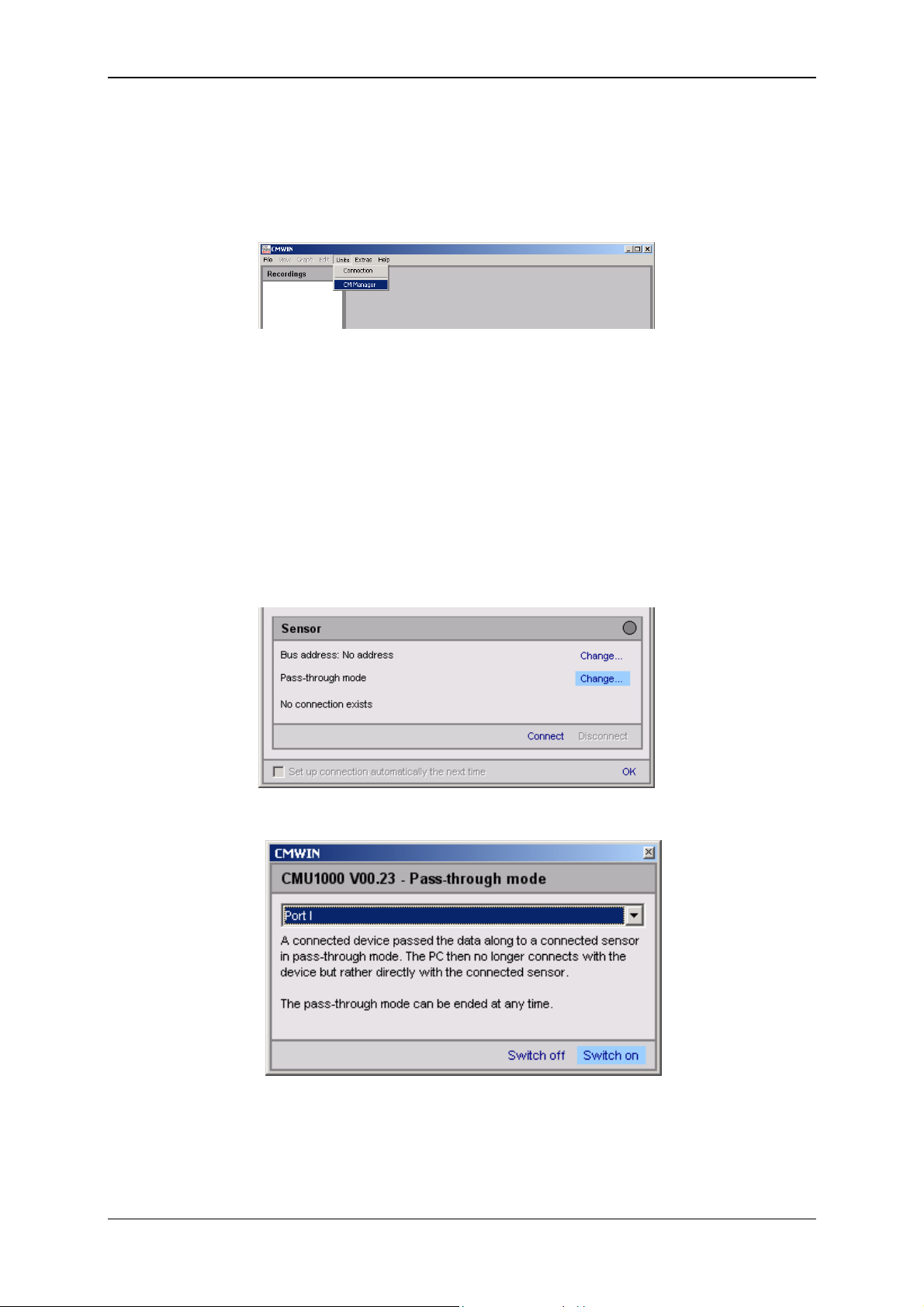
• Start the HYDAC PC software CMWIN
• In the Units Menu, select the "CM Manager" option.
• If the Connection window does not open automatically, select
"Connection" in the menu bar of the CM Manager.
• Under Interface Settings make the settings necessary for the available
connection type (for configuring the CSI-F-10).
• Click on “OK“ to apply the settings or “Cancel“ to discard these changes. In
either case you will then return to the Connection window.
• Click on Open to open the selected interface. The opened interface is indicated
by a green dot at the top right.
• Select "Change" in the Pass-through mode line. The following window opens:
• In the drop-down menu, select "Port I" and then click on Switch on in order to
switch on the pass-through mode.
Revised 17.12.2009 HYDAC ELECTRONIC GMBH Mat.-No.: 669749
Page 39
Condition Monitoring Unit CMU 1000 Page 39
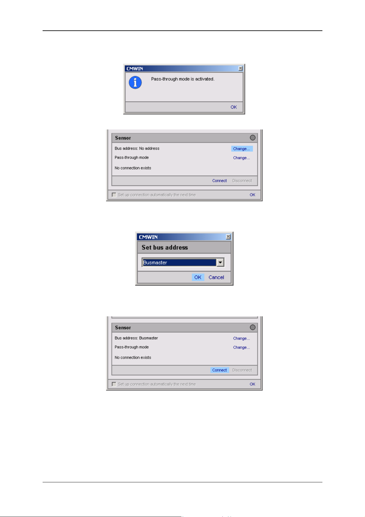
• The following message appears:
• Select "Change" in the Bus address line. The following window opens:
• In the selection window, select "Busmaster" and then click on OK to apply the
address.
• Then click on "Connect" to connect the PC to the CSI-F-10 GSM radio module
(address busmaster).
Revised 17.12.2009 HYDAC ELECTRONIC GMBH Mat.-No.: 669749
Page 40
Condition Monitoring Unit CMU 1000 Page 40
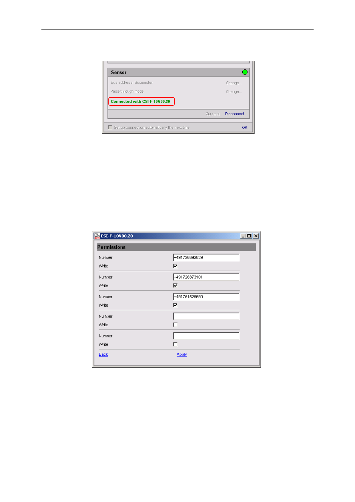
• Successful establishment of the connection will be signaled as shown below:
• End the connection setup by confirming with OK.
• In the CM Manager under Actions / Performing a Dialog / Permissions, open
the following input window and input the mobile phone number authorized for
accessing the CMU 1000.
• Permissions
Number [input telephone number with country code]
Write [allow written access]
You can input up to five telephone numbers to which the CSI-F-10 may send
messages and from which the device may receive enquiry text messages.
By placing a checkmark in the "Text" box, you are also allowing access by text
to the CSI-F-10 from this telephone number (change settings, transfer CM
program, update firmware, ...)
Click on "Apply", to apply the settings. "Back" takes you back to the main
menu.
Revised 17.12.2009 HYDAC ELECTRONIC GMBH Mat.-No.: 669749
Page 41
Condition Monitoring Unit CMU 1000 Page 41
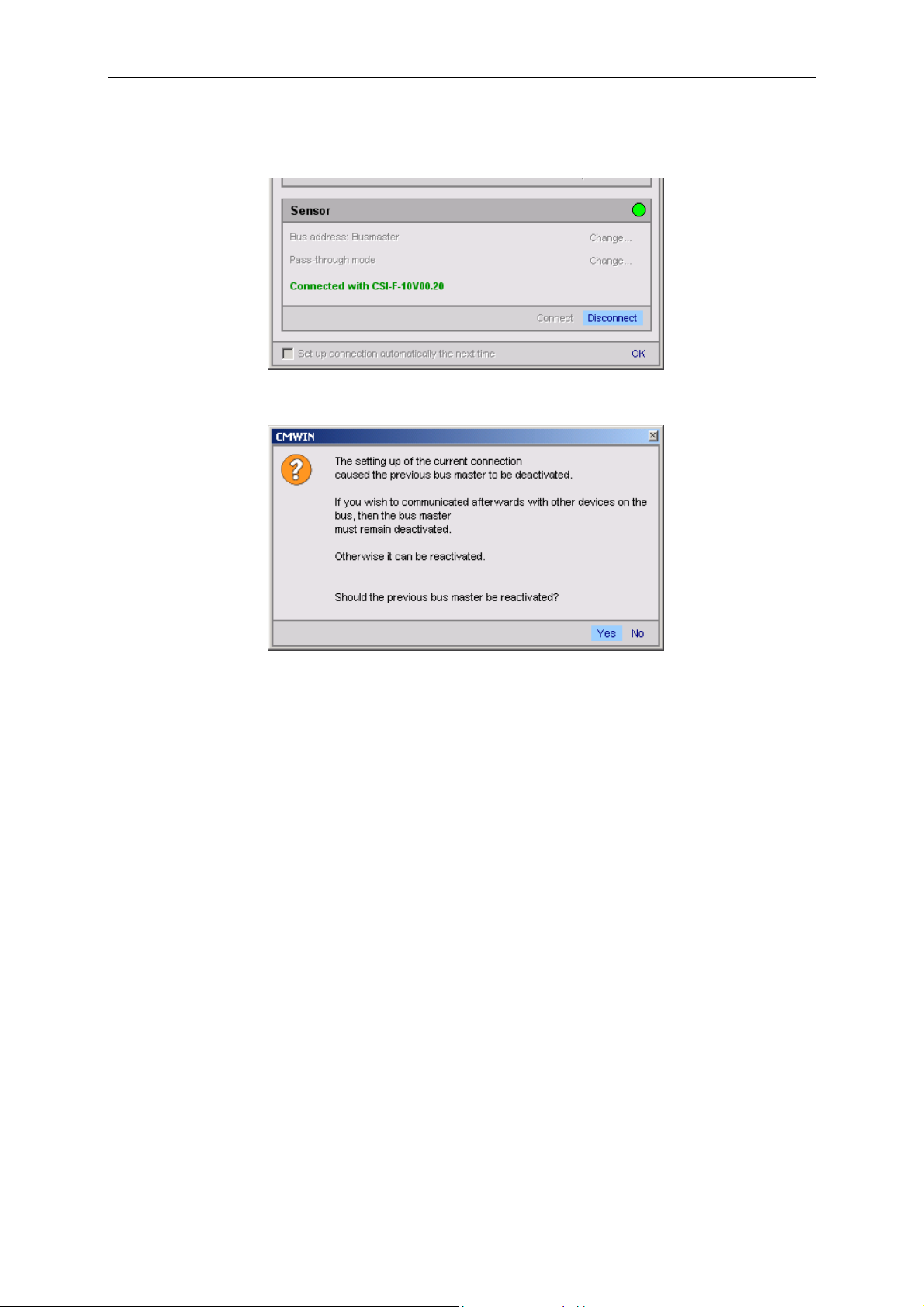
• Click on "Disconnect" under Connection in the Device box to break the
existing connection with the CSI-F-10.
• The following window opens:
• Then click on "Yes" to reactivate the busmaster again.
Revised 17.12.2009 HYDAC ELECTRONIC GMBH Mat.-No.: 669749
Page 42

Condition Monitoring Unit CMU 1000 Page 42
5.2.3.3 Connection Setup with CMU 1000 using GSM Mobile Network
• Start the HYDAC PC software CMWIN
• In the Units Menu, select the "CM Manager" option.
• If the Connection window does not open automatically, select
"Connection" in the menu bar of the CM Manager.
• Mark the "Modem Connection" option in the window that opens.
• Click on "Change" to open the window for the interface settings.
• Make the corresponding preselection for the port settings in the window that
opens under Interface selection.
• Select the respective port address and Baud rate under Interface settings.
• Pressing "Refresh" causes the interfaces marked under Interface selection to
be refreshed in terms of availability.
• Click on “OK“ to apply the modified settings or “Cancel“ to discard these
changes. In either case you will then return to the Connection window.
• Click on "Change" to open the window for entering the telephone numbers.
• Enter the telephone number of the SIM card mounted in the GSM module
CSI-F-10.
• In the Pin box, input the pin code given for the SIM card which is operated in
the GSM modem in the PC (not for the SIM card in the CSI-F-10!). If no PIN
code has been assigned, then leave this box empty.
Revised 17.12.2009 HYDAC ELECTRONIC GMBH Mat.-No.: 669749
Page 43

Condition Monitoring Unit CMU 1000 Page 43
• You can set up a list of telephone numbers (address book) with Telephone list.
• Click on “OK“ to apply the entries or “Cancel“ to discard these changes. In
either case you will then return to the Connection window.
• Click on Open to open the selected interface. The opened interface is indicated
by a green dot on the upper right.
• Click on "Change" to open the window for the pass-through mode.
• Select the HSI address of the CMU 1000 connected to the CSI-F-10 in the
selection window (Address a in our example).
• Afterwards, click on Switch on in order to switch on the pass-through mode for
the selected channel.
Revised 17.12.2009 HYDAC ELECTRONIC GMBH Mat.-No.: 669749
Page 44

Condition Monitoring Unit CMU 1000 Page 44
• The following message appears:
• Confirm this with OK.
• Afterwards click on Connect to connect the PC to the CMU 1000 that is
connected with the CSI-F-10
• The successful establishment of the connection will be signalled as shown
below:
• End the connection setup by confirming with OK.
Revised 17.12.2009 HYDAC ELECTRONIC GMBH Mat.-No.: 669749
Page 45

Condition Monitoring Unit CMU 1000 Page 45
5.2.4 TCP Connection
As a third option, you can set up a link between the PC and the CMU 1000 by means
of an Ethernet network.
In the following we present an example of this kind of link.
5.2.4.1 Device Connection
Use one Standard RJ45 cable each to connect your PC and the CMU 1000 to a
shared Ethernet network.
Note!
In order to be able to set up a connection via Ethernet, the network settings and
parameters in the CMU 1000 must first be correctly stored.
See in this connection Chapter 5.1.1/5.1.2 "Operation on the Device" and 5.2.5.5
"Performing a Dialog".
Example:
Ethernet (company / factory bay / system network)
5.2.4.2 Connection Setup
• Start the HYDAC PC software CMWIN
• In the Units Menu, select the "CM Manager" option.
• If the Connection window does not open automatically, select
"Connection" in the menu bar of the CM Manager.
• Mark the option "TCP Connection" option in the window that opens.
• Click on "Modify" to open the window for the interface settings.
Revised 17.12.2009 HYDAC ELECTRONIC GMBH Mat.-No.: 669749
Page 46
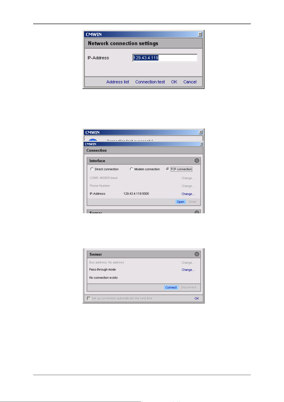
Condition Monitoring Unit CMU 1000 Page 46
• Enter the IP Address stored in the network settings of the CMU 1000.
• You can set up a list of addresses (address book) with Address list.
• With Connection test you can test the link from the PC to the CMU 1000. If the
IP Address has been entered correctly, then the following message will appear:
• Click on “OK“ to apply the entries or “Cancel“ to discard these changes. In
either case you will then return to the Connection window.
• Click on Open to open the selected interface. The opened interface is indicated
by a green dot on the upper right.
• Afterwards click on Connect to connect the PC to the CMU
• The successful establishment of the connection will be signalled as shown
below:
Revised 17.12.2009 HYDAC ELECTRONIC GMBH Mat.-No.: 669749
Page 47

Condition Monitoring Unit CMU 1000 Page 47
• End the connection setup by confirming with OK.
Revised 17.12.2009 HYDAC ELECTRONIC GMBH Mat.-No.: 669749
Page 48
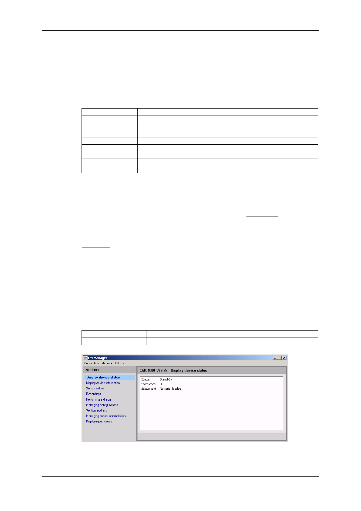
Condition Monitoring Unit CMU 1000 Page 48
5.2.5 Actions
5.2.5.1 Display Device Status
• Status
The "Status" indicates the current condition of the device. The individual
conditions can be be specified in greater detail via the following table.
Ready No active error present, device is ready for operation
Stand-By No active error present, but device is currently not ready for
operation; it may be that individual device functions are switched
off or the device is in a startup phase, etc.
Minor error A minor error is present which can be acknowledged.
Moderate error A medium-serious error is present, which may possibly be
eliminated by switching On/Off.
Serious error A serious error is present; the unit must be sent in to the
manufacturer.
• Status code
The "Status code" is dependent on the CM Program present in the device and
reflects the conditions of the Boolean output values used in the program.
For this, the Boolean output values are displayed from right to left
binary sequence, i.e. the lowest-value bit corresponds to the Boolean output
value 0.
Example:
0 = No Boolean output values used in the program
1 0 1 0 = Boolean output value 0 = 0 (LSB)
Boolean output value 1 = 1
Boolean output value 2 = 0
Boolean output value 3 = 1
• Status text
The "Status text" indicates whether or not a CM Program is available in the
device.
No script loaded No CM Program is available in the device.
Script in execution A CM Program is available in the device.
in ascending
Revised 17.12.2009 HYDAC ELECTRONIC GMBH Mat.-No.: 669749
Page 49

Condition Monitoring Unit CMU 1000 Page 49
5.2.5.2 Display Device Information
• Here the values of the following status parameters are displayed:
- Part numer
- Serial number
- Channel information
The Channel information reflects the numerical input values from the CM
Program. Channel 0 corresponds thereby to the first numerical input value in
the CM Program, Channel 1 the second one, etc.
920112
PT 0011
If no CM Program is available in the device, then the connected sensors will be
displayed in this position with measurement range and unit.
920112
PT 0011
5.2.5.3 Sensor Values
• Here the result values (Numerical output values) from the CM Program in the
device are displayed.
If no CM Program is available in the device, then the measured values of the
connected sensors will be displayed.
Revised 17.12.2009 HYDAC ELECTRONIC GMBH Mat.-No.: 669749
Page 50
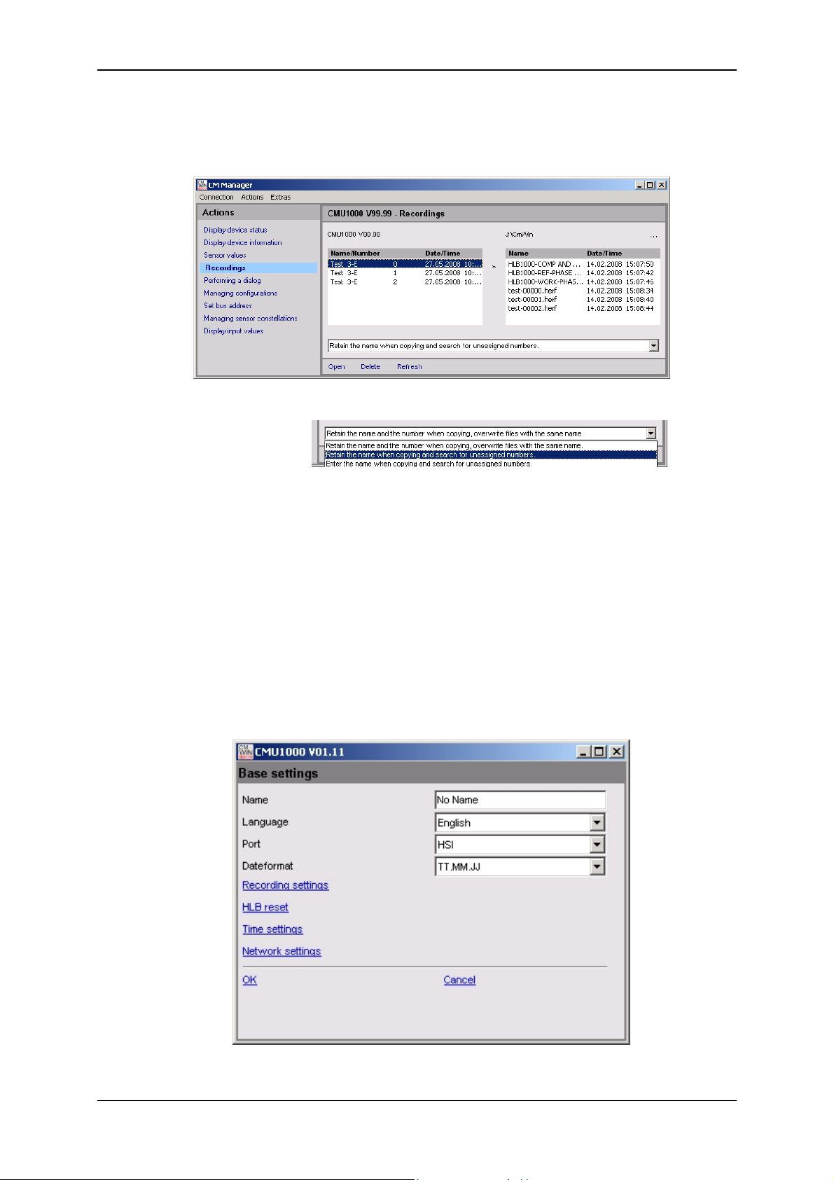
Condition Monitoring Unit CMU 1000 Page 50
5.2.5.4 Managing Recordings
• Here you can manage the recordings stored in the CMU 1000
(copying, opening, updating, deleting)
You have the following options for saving and copying:
5.2.5.5 Performing a Dialog
This menu option corresponds to the menu option "Settings" in the internal device
structure for the purpose of configuring the CMU 1000.
The following settings can be made:
Base settings
• Name
• Port [RS232 / HSI]
• Language [German / English / French
• Dateformat [TT.MM.YY / MM/TT/YY / YY-MM-TT]
Revised 17.12.2009 HYDAC ELECTRONIC GMBH Mat.-No.: 669749
Page 51

Condition Monitoring Unit CMU 1000 Page 51
Recording settings
Here you specify whether you wish the recorded data held in the internal memory
to be deleted after copying onto a USB stick and whether, after the CMU reboots,
to generate a new record file or to continue with the previous one.
• Delete recordings after copy [ yes / no]
• Continue recording [ yes / no]
HLB reset
Here you can reset an HLB connected to Channel A .. H
(delete memory).
• HLB Reset [ yes / no]
• Sensor [Select sensor A .. H]
Time settings
• Date [Enter Date]
• Time [Enter Time]
Revised 17.12.2009 HYDAC ELECTRONIC GMBH Mat.-No.: 669749
Page 52
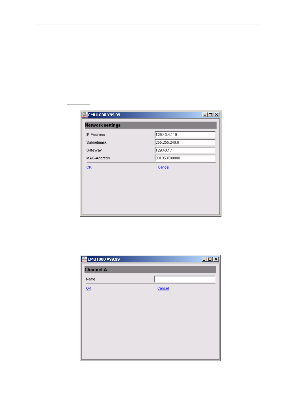
Condition Monitoring Unit CMU 1000 Page 52
Network settings
If the CMU 1000 is integrated in a network at the customer site, then the following
settings need to be carried out in accordance with this network:
• IP Address [enter IP Address]
• Subnetwork mask [enter Subnetwork mask]
• Gateway Address [enter Gateway Address]
• MAC Address [permanently set at the factory, read-only]
Example:
Peripherals - Channel Settings
• Channel A to Channel H (HSI channels)
- Name [Enter name]
Revised 17.12.2009 HYDAC ELECTRONIC GMBH Mat.-No.: 669749
Page 53

Condition Monitoring Unit CMU 1000 Page 53
• Channel I to Channel P
- Name [Enter name]
- Mode [Off / Manual / Autodetect]
- Input signal *) [HSI / 0..20 mA / 4..20 mA /
0..5 V / 0..10 V / 0.5..4.5 V / 0..50 V /
0.5..5.5 V / 1..5 V / 1..6 V / -10..+10 V]
- Low range [Enter low range]
- High range [Enter high range]
- Decimal format [0 / 0.0 / 0.00 / 0.000]
- Unit [Enter unit]
*) Possible input signals channel-dependent
• Channel Q and Channel R
Name [enter Name]
Mode [Off / Active]
High range [enter High range]
Factor [enter Factor]
Decimal format [0 / 0.0 / 0.00 / 0.000]
Unit [enter Unit]
Peripherals - PWM settings (Analog outputs)
Revised 17.12.2009 HYDAC ELECTRONIC GMBH Mat.-No.: 669749
Page 54

Condition Monitoring Unit CMU 1000 Page 54
• PWM 1, PWM 2 (Analog output 1, Analog output 2)
You use the PWM settings to establish which type of signal is to be available at
the two analog ouputs.
Revised 17.12.2009 HYDAC ELECTRONIC GMBH Mat.-No.: 669749
Page 55
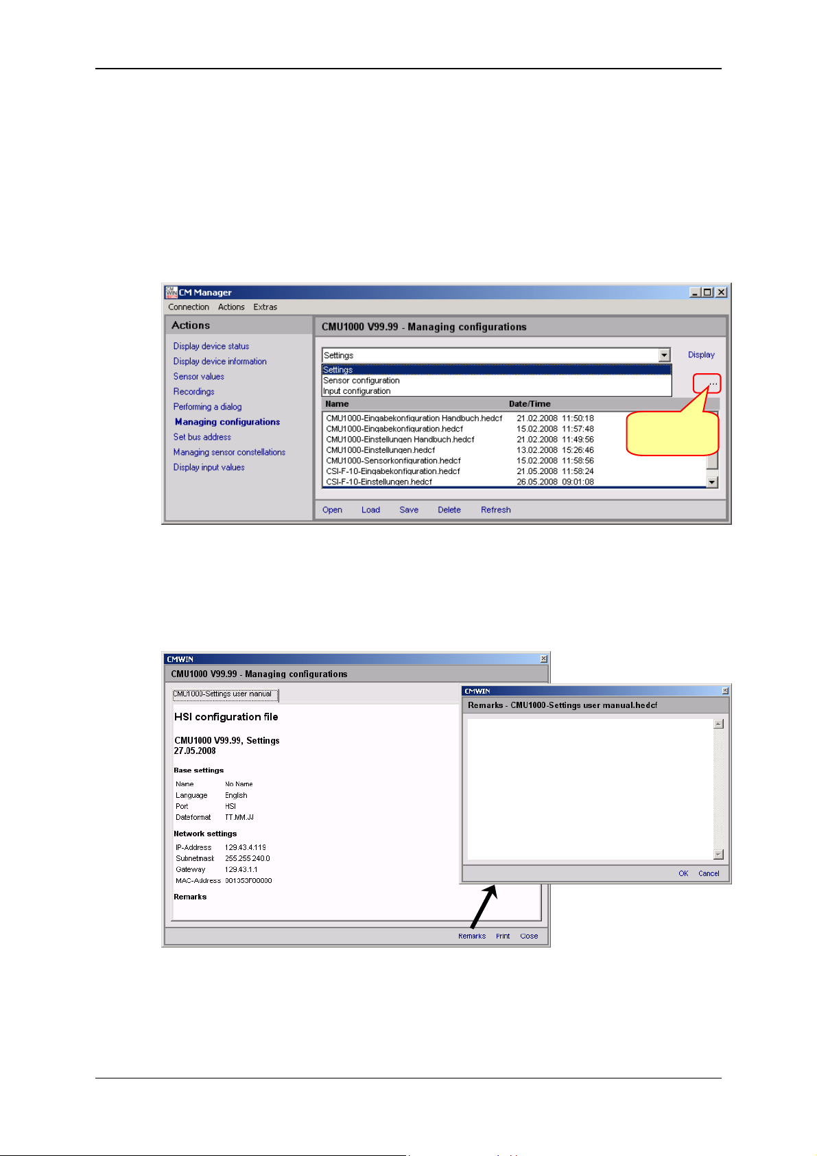
Condition Monitoring Unit CMU 1000 Page 55
5.2.5.6 Managing Configurations
Here you can generate and manage various configuration files. These configuration
files can, for example, be generated in series on a "Master" CMU and then
subsequently loaded onto an unlimited number of other CMUs.
The following configuration files can be generated and managed:
• Settings configuration
• Sensor configuration
• Input configuration
Selection
target folder
- With Open you can call up the display of the content of a configuration file listed
in the lower display field. To accomplish this, mark the desired file with a mouse
click. You can add remarks to the content and print out the file in the window that
then opens automatically.
Revised 17.12.2009 HYDAC ELECTRONIC GMBH Mat.-No.: 669749
Page 56
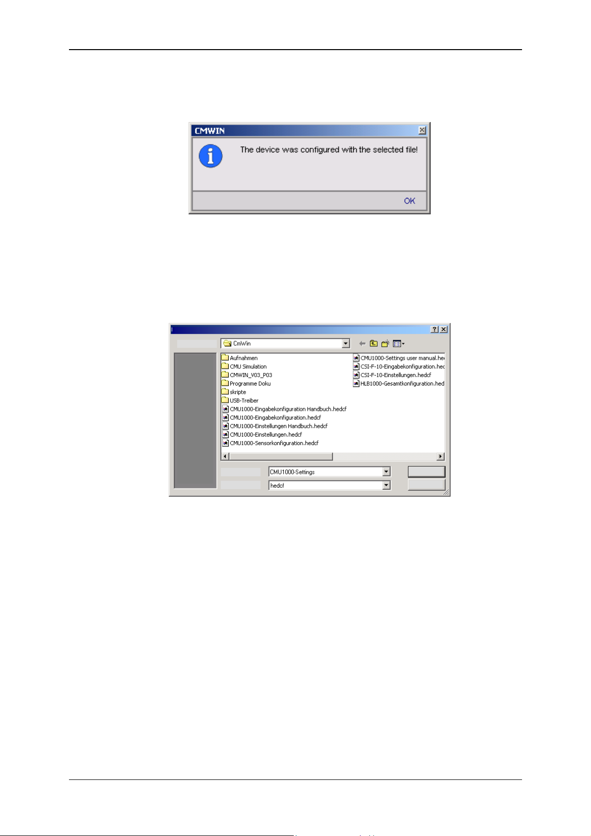
Condition Monitoring Unit CMU 1000 Page 56
- With Load you can transfer a configuration file (marked in the lower display field)
from the PC to the CMU 1000. The following message appears after the
completion of the transfer:
All of the settings stored in the configuration file were carried out after the transfer
of the file in the CMU 1000.
- When you press Save, you generate a new configuration file or save a modified
one to the previously specified target folder (in our example: C:\Temp). The
following window opens for this purpose:
File save as
Save in:
File name:
File type:
Save
Cancel
- Pressing Delete causes the configuration file in the target folder marked in the
lower display field to be deleted.
- Pressing Refresh causes the display field for the configuration files to be
updated. The defined target folder will be read out again for this purpose.
This is necessary, e.g. when you copy or delete configuration files with Windows
Explorer. These changes will not be displayed in the folder until after "Refresh"
has been carried out in CMWIN.
- With Display you can display the respective momentary "Actual Configuration" of
the connected CMU 1000.
The individual configuration files are explained briefly in the following:
Revised 17.12.2009 HYDAC ELECTRONIC GMBH Mat.-No.: 669749
Page 57

Condition Monitoring Unit CMU 1000 Page 57
• Settings
The basic settings and the network settings are stored in the Settings
Configuration file.
• Sensor configuration
The peripherals settings are stored in the Sensor Configuration file.
Revised 17.12.2009 HYDAC ELECTRONIC GMBH Mat.-No.: 669749
Page 58

Condition Monitoring Unit CMU 1000 Page 58
• Input configuration
The values of the numerical and Boolean input values used in the CM Program
are stored in the input configuration file.
5.2.5.7 Set bus address
Here you can assign the CMU 1000 an "HSI Bus address". This is required when
several CMU 1000 (or other HYDAC CM devices) are connected to one HSI Bus
and these devices are all set up to be be addressed by a central PC. A total of a
maximum of 26 HYDAC CM devices can be linked to one HSI Bus, i.e. you can
assign the addresses "a" to "z" (see Chap. 5.2.2. CMU 1000 at the HSI Bus).
If the CMU 1000 is operated as a single device, then the bus address setting is not
required; it is not relevant for operational purposes.
The standard setting is "Address a".
Revised 17.12.2009 HYDAC ELECTRONIC GMBH Mat.-No.: 669749
Page 59

Condition Monitoring Unit CMU 1000 Page 59
5.2.5.8 Managing Sensor Constellations
Reliable system monitoring means ensuring that exactly the same sensors that
were connected at the time the CMU 1000 was configured are connected during
operation.
The sensor constellation is used for this purpose. The sensor constellation is a
monitoring instrument for the connected sensor system, i.e. it performs a
continuous comparison between the connected "Actual" sensor system and the
specified "Nominal" sensor system.
(see Chap. 6.1.5. Sensor Constellation)
You can use this function to generate and manage various sensor constellation
files. These constellation files can, like the configuration files, be generated on a
"Master" CMU and then subsequently loaded onto an unlimited number of other
CMUs.
If no sensor constellation has yet been generated in the device then the following
window opens:
• You can generate a new sensor constellation in the device by pressing Create
(in the upper command bar). Afterwards, the following message appears:
• You can have the momentarily current sensor constellation in the device
displayed by pressing Display (in the upper command bar).
• You can delete the momentarily current sensor constellation in the device
displayed by pressing Delete (in the upper command bar).
All other functions in the lower command bar (Open, Load, Save, Delete, etc.) and
the selection of the target folder for saving the files are identical with Chapter
5.2.2.6, "Managing configurations".
Revised 17.12.2009 HYDAC ELECTRONIC GMBH Mat.-No.: 669749
Page 60

Condition Monitoring Unit CMU 1000 Page 60
5.2.5.9 Display Input Values
• Here the current measured values and statuses of the analog (also HSI and
SMART) and digital sensors connected to the CMU 1000 are displayed
Revised 17.12.2009 HYDAC ELECTRONIC GMBH Mat.-No.: 669749
Page 61

Condition Monitoring Unit CMU 1000 Page 61
5.2.6 Extras
5.2.6.1 Update Firmware
Caution
The voltage supply to the CMU 1000 is not permitted to be interrupted during the
firmware update. If the voltage supply fails during the update process, then troublefree functioning can no longer be ensured and the device must be sent back to
HYDAC SERVICE GMBH.
• You can update the firmware of your CMU 1000 after selecting this menu
option. The following window opens for this purpose:
• Follow the instructions and confirm with Continue. In the window that opens,
select the corresponding Update file and click on Open.
Search in:
File name:
File type:
Open
Cancel
• Follow the instructions in the following window:
Revised 17.12.2009 HYDAC ELECTRONIC GMBH Mat.-No.: 669749
Page 62

Condition Monitoring Unit CMU 1000 Page 62
• Confirming with Continue will cause the data to be transferred to the
CMU 1000.
• Confirming with Continue will cause the data in the CMU 1000 to be checked,
and then the two following windows will appear one after the other:
Revised 17.12.2009 HYDAC ELECTRONIC GMBH Mat.-No.: 669749
Page 63

Condition Monitoring Unit CMU 1000 Page 63
• Confirming again with Continue will activate the new firmware in the device.
The following messages will appear one after the other in the CMU 1000
display for this purpose for approximately 10 seconds:
SSuubb CCPPUU UUppddaattee
DDoonn''tt ttuurrnn oofff
f
MMaaiinn CCPPUU uuppddaattee
DDoonn''tt ttuurrnn oofff
f
Afterwards, the CMU 1000 reboots with the updated firmware.
• The following window opens as the last one in the sequence in the CMWIN.
Pressing Close returns you to the CM Manager.
Note!
All settings, configurations, constellations and the CM program are retained and not
overwritten when the firmware is updated.
Revised 17.12.2009 HYDAC ELECTRONIC GMBH Mat.-No.: 669749
Page 64
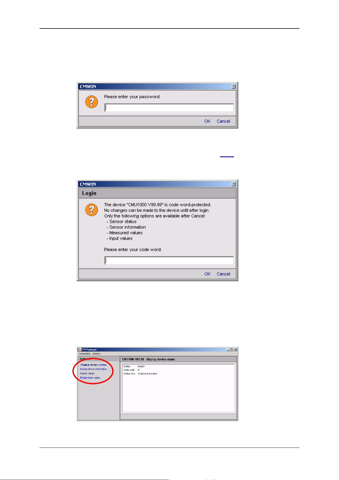
Condition Monitoring Unit CMU 1000 Page 64
5.2.6.2 Set Password Protection
• To prevent unauthorized access to the CMU 1000, you can equip the device
with password protection. Select the function Set password protection for this
purpose. The following window opens:
You are prompted at this point to enter a password. If the CMU 1000 is still in
the condition it was at the time of delivery or if no password protection has been
set, then the standard password for this function is: 0000
.
Afterwards, disconnect the link to the CMU 1000 and then reconnect it. The
following window opens:
- Enter the Password and then click on OK in order to have unlimited access to
the CMU 1000.
- If you click on Cancel without entering a password, then you will obtain only
"Reading Rights". You can only access the following information:
Sensor status, sensor information, measured values, input values
The CM Manager is reduced in such cases to the following functions:
It was not possible to carry out any settings.
Revised 17.12.2009 HYDAC ELECTRONIC GMBH Mat.-No.: 669749
Page 65

Condition Monitoring Unit CMU 1000 Page 65
5.2.6.3 Change Password
• Here you have the opportunity of changing the password. After the Change
passwort function has been selected, the following window opens:
- Enter the previous password in the top line.
- Enter the new password in the middle line.
- Repeat the new password in the bottom line.
- Confirm the action with OK (the new password is immediately activated) or
end the action by clicking on Cancel without changing the password.
5.2.6.4 Removing Password Protection
• To remove the password protection in the device again, select the function
Remove password protection. The following window opens:
- Enter the currently valid password.
- Confirm the action with OK (password protection is immediately deactivated)
or end the action by clicking on Cancel without deactivating the password
protection.
5.2.6.5 Send Commands
• With this menu option it will be possible with future device versions to send
direct commands to the CMU 1000 in order to initiate certain functions there.
This menu option has no function at present.
Revised 17.12.2009 HYDAC ELECTRONIC GMBH Mat.-No.: 669749
Page 66
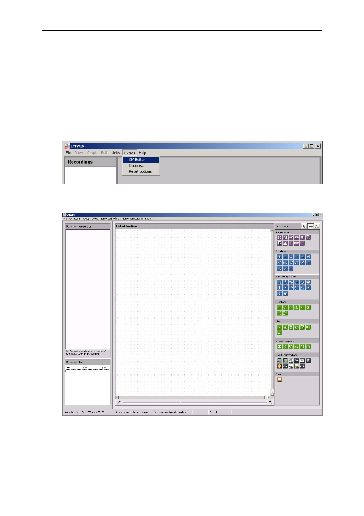
Condition Monitoring Unit CMU 1000 Page 66
6 CM Editor
The CMU 1000 processes your program in continuous cycles. You generate the
program with the CM Editor and load it afterwards into the CMU 1000.
The CM Editor is a constituent part of the HYDAC PC software CMWIN starting with
Version 3 and provides you with various tools and functions for designing, integrating
and testing your CM program.
To open the Editor, proceed as follows:
• Start the HYDAC PC software CMWIN
• In the Extras Menu, select the "CM Editor" option.
• The following screen opens:
The menu structure and window properties of the Editor are explained below in greater
detail:
Revised 17.12.2009 HYDAC ELECTRONIC GMBH Mat.-No.: 669749
Page 67

Condition Monitoring Unit CMU 1000 Page 67
6.1 Menu Bar
The menu bar of the CM Editor is tailored to the MS Windows user interface and
contains the following menu structure:
6.1.1 File
• With "New", you can establish for which platform (CM device) the CM program
is to be created before beginning the actual creation of the CM program. The
program functions which are not available for the selected platform will be
suppressed in gray tones in the Functions window and will not be able to be
used during the program generation.
• With "Platform", you can establish for which platform (CM device) the CM
program is to be created during the creation of a CM program. The program
functions which are not available for the selected platform will be suppressed in
gray tones in the Functions window and will not be able to be used during the
program generation.
• Pressing "Open" allows you to open an already generated and stored CM
program. CM programs use the file extension *.hecmp. Select the desired file in
the corresponding path for this purpose.
• Select "Save" to save a CM program. If the recording has not yet been saved,
the “Save as…“ window will open. Enter the desired file name for this purpose
in the respective path.
• To save a file that has not yet been saved or to save a file that has already
been saved under a different name, select "Save as ...", Enter the desired file
name for this purpose in the respective path.
• To integrate an existing program that has already been saved into the current
program generation process, select "paste from file". Select the desired file in
the corresponding path for this purpose.
• Press "Print" to print out the content of the Linked functions window
(= program printout).
• Press "Quit" to close the CM Editor.
Revised 17.12.2009 HYDAC ELECTRONIC GMBH Mat.-No.: 669749
Page 68
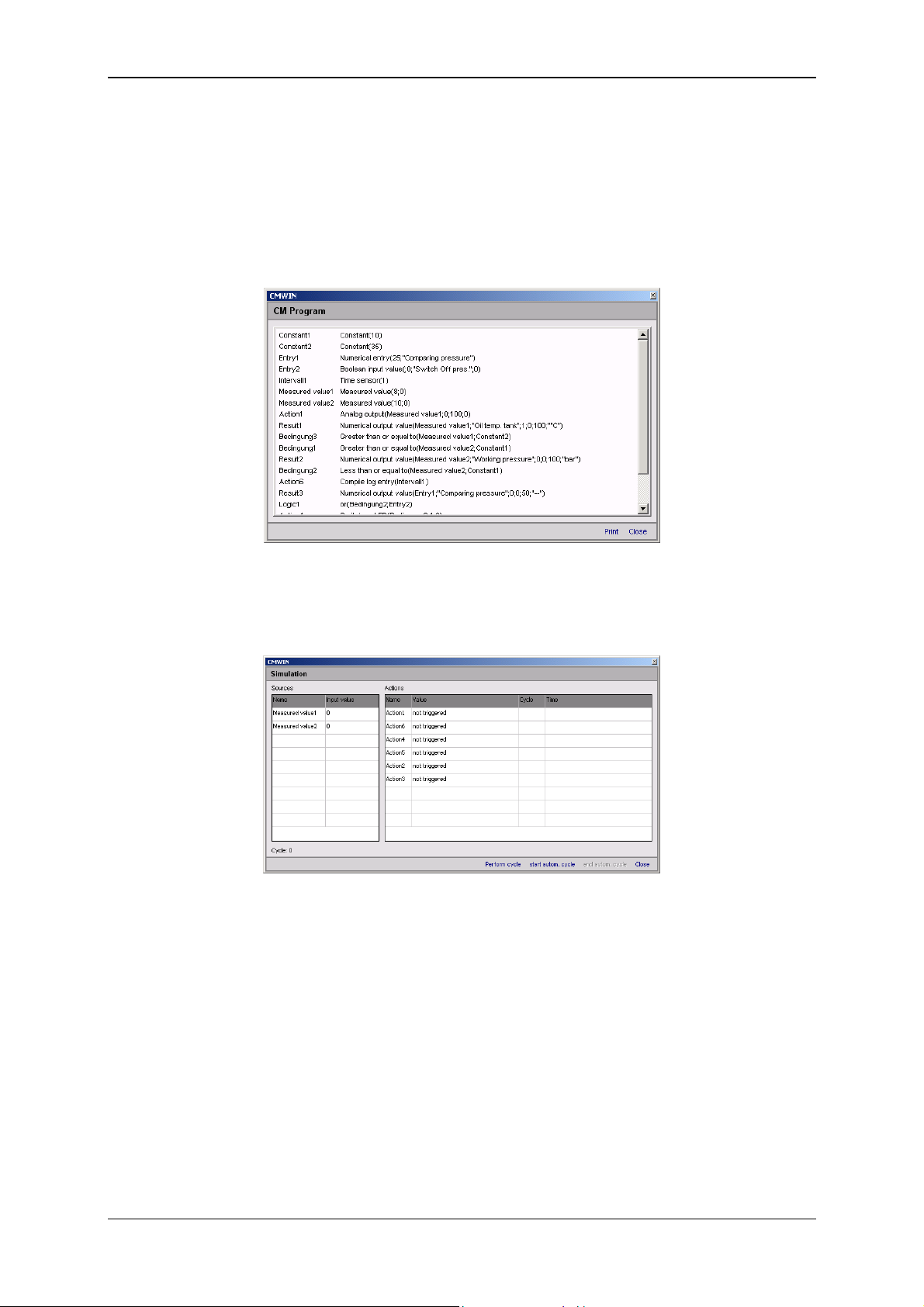
Condition Monitoring Unit CMU 1000 Page 68
6.1.2 CM Program
• After "Display" is selected, a window opens in which all of the functions used in
the currently opened CM program will be listed, together with inscriptions and
parameters.
The list can be printed out by selecting "Print".
Pressing "Close“ takes you back to the CM Editor.
• With "Simulate", you can simulate and/or test the CM program that is currently
open. The Simulation window opens for this purpose. No connection with the
CMU 1000 is required for the simulation.
All of the input signals used in the CM program are listed one above the other
in the Name column in the left-hand part of the Simulation window.
You can assign a specific value to each input in the Input value column.
All of the actions used in the CM program are listed one above the other in the
Name column in the right-hand part of the Simulation window.
The current status of each action is displayed in the Value column.
The cycle number of the last status modification is displayed in the Cycle
column.
The date and time of the last status modification is displayed in the Time
column.
Revised 17.12.2009 HYDAC ELECTRONIC GMBH Mat.-No.: 669749
Page 69
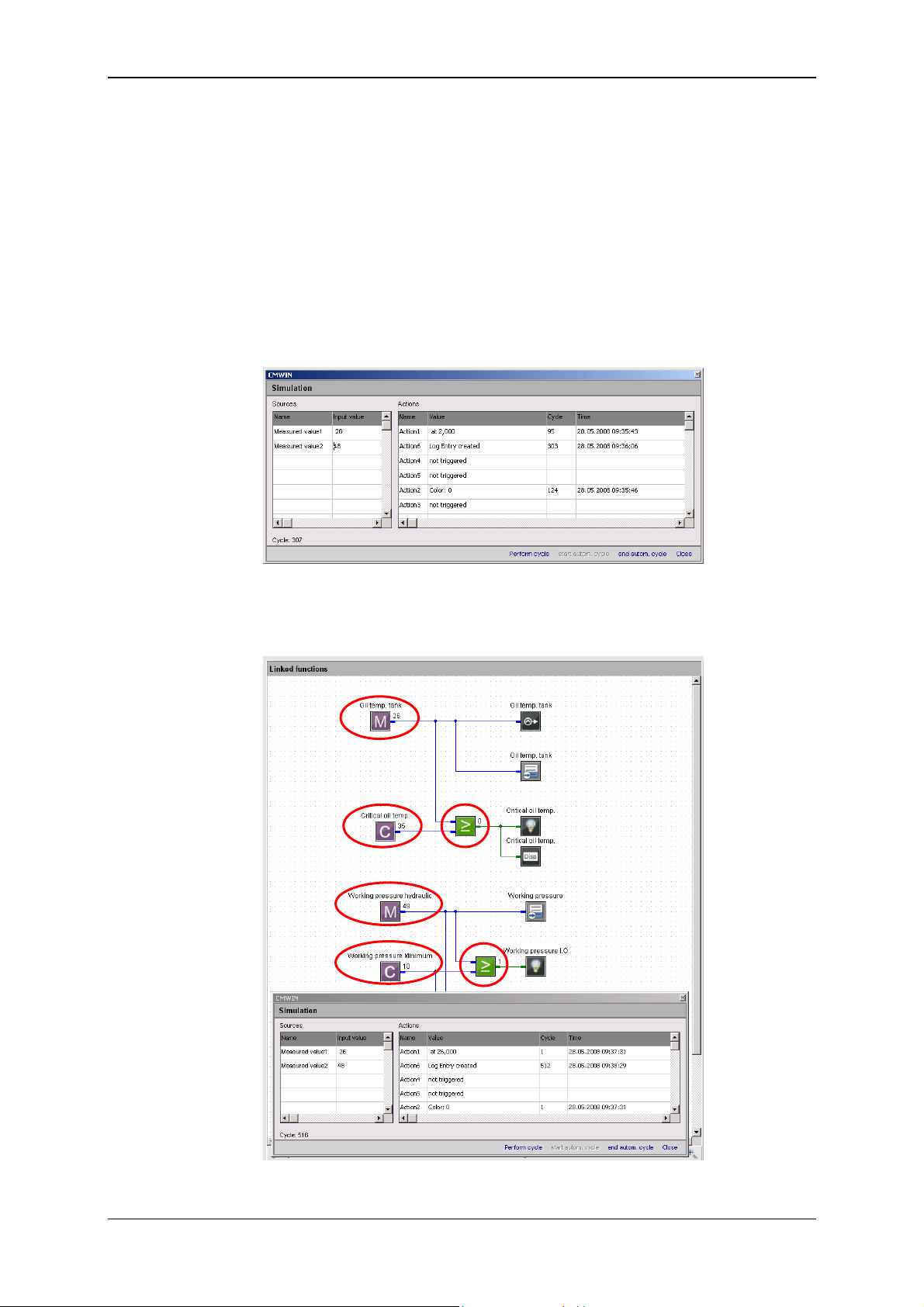
Condition Monitoring Unit CMU 1000 Page 69
With "Perform cycle", you can start the simulation for a single processing
cycle and then view the thereby resulting status modifications of the actions
afterwards.
With "Start autom. cycle“, you start a permanent, continuous program
simulation. You can change the input values during the simulation any way
you like and observe the status modifications of the actions.
Mit "End autom. cycle“, you stop the permanent, continuous program
simulation.
Pressing "Close“ takes you back to the CM Editor.
During the simulation, the assigned input values and action statuses are also
displayed in the Linked Functions window at the corresponding symbols.
Revised 17.12.2009 HYDAC ELECTRONIC GMBH Mat.-No.: 669749
Page 70
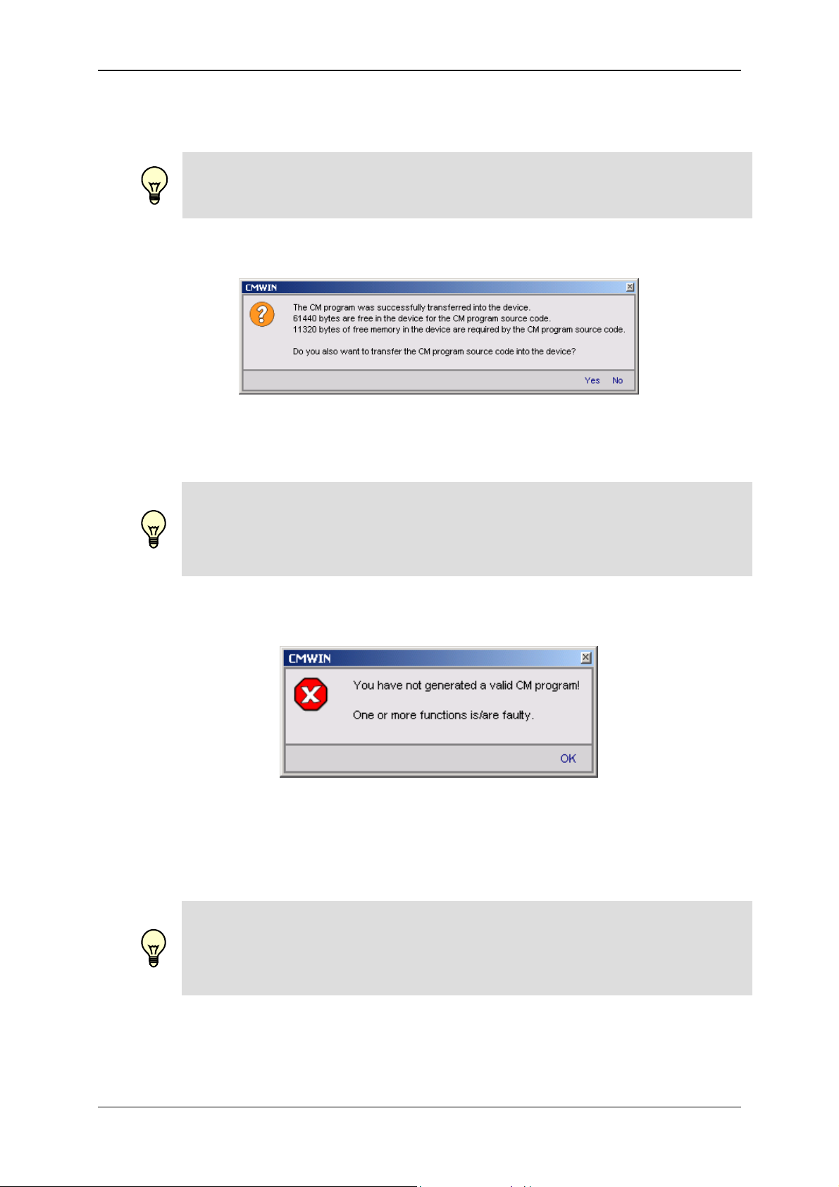
Condition Monitoring Unit CMU 1000 Page 70
• You can transfer the currently opened CM program to the CMU 1000 with
"Transfer into device“.
Note!
Only error-free programs can be transferred into the CMU 1000.
The following message appears after the program has been successfully
applied:
Here you can select whether you also wish to transfer the source code of the
program into the CMU 1000.
Note!
If you transfer the source code into the CMU 1000 as well, then it is possible
for it to be read out again from every other connected PC and modified! If the
source code is not transferred as well into the CMU 1000, then the program
cannot be read out from another PC.
The following message will appear if the CM program is not error-free:
Eliminate the error(s) found in the CM program (see in this connection
Chap. 6.2.2., "Function List" Window and Chap. 8, "Error messages") and
transfer the program again.
Note!
If you transfer a program and a power failure occurs during the transfer, then
the program will not be saved in the CMU 1000 after power is restored. For
that reason, first save your program on the PC on which it was originally
generated or modified before making the transfer.
Revised 17.12.2009 HYDAC ELECTRONIC GMBH Mat.-No.: 669749
Page 71
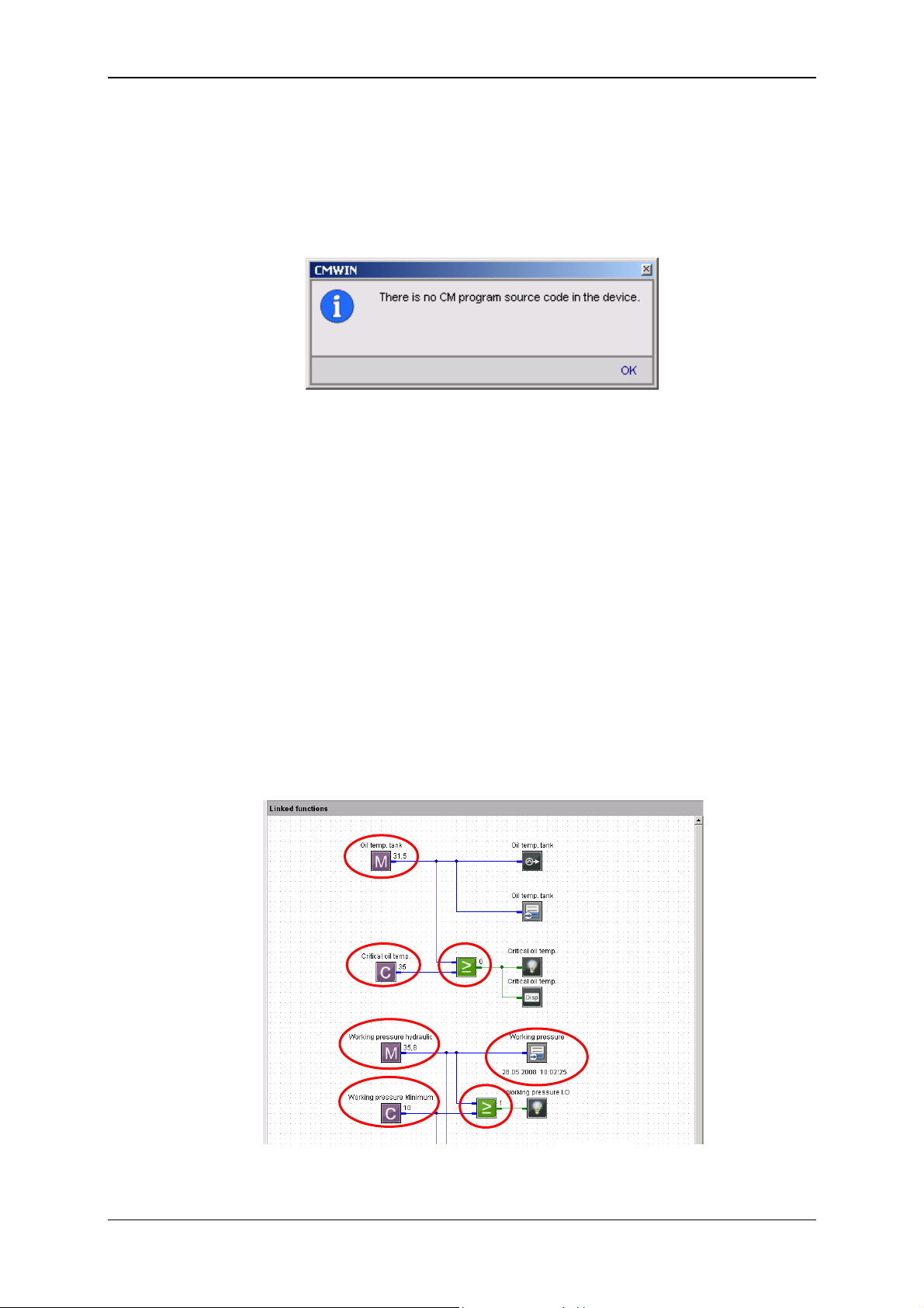
Condition Monitoring Unit CMU 1000 Page 71
• You can transfer and then edit the CM program currently available in the CMU
to your PC with "Receive from device". This will however only work if the CM
program source code from the original creator has also been transferred into
the CMU 1000.
If no source code is available in the CMU 1000, then the following message will
appear:
• The "Online Debugging" function is a tool for observing the CM program as
well as for finding, diagnosing and eliminating possible errors in the CM
program and/or in the connected peripherals.
The following prerequisites must be fulfilled for this purpose:
- The CMU 1000 must be connected with the PC and the CMWIN software.
- The CM program opened in CMWIN and the one active in the CMU 1000
must be identical.
If the "Online Debugging" mode is active, then the following values will be
displayed at the respective functions:
- Measured values
- Constants
- Switching status of logical links
- Date and time when initiating the corresponding event
The display in "Online Debugging" mode is shown in exemplary fashion in the
following illustration:
Revised 17.12.2009 HYDAC ELECTRONIC GMBH Mat.-No.: 669749
Page 72
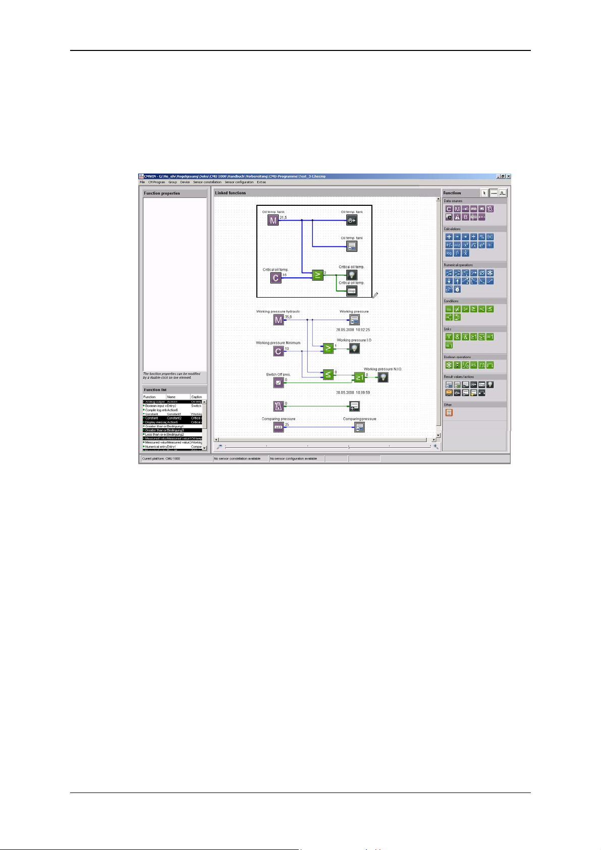
Condition Monitoring Unit CMU 1000 Page 72
6.1.3 Grouping
• With Create grouping you can join several functions to make an
interconnected unit and transfer and copy these as a block.
First mark the functions to be grouped by enclosing them in a frame created
with the help of the cursor.
Afterwards, select “Group“ in the menu bar and then “Create grouping“ in the
drop-down menu that appears.
• Pressing “Cancel grouping“ releases the functions linked together in the group
from one another again.
To accomplish this, mark the desired group with a mouse click on any one of
the functions within the group.
Afterwards, select “Group“ in the menu bar and then “Cancel grouping“ in
the drop-down menu that appears.
6.1.4 Device
The "Connection“ function can be used to set up a connection between the PC and a
CMU 1000 from the CM Editor.
The function is identical with the connection setup in the CM Manager. See in this
connection Chap. 5.2.1. ff.
Revised 17.12.2009 HYDAC ELECTRONIC GMBH Mat.-No.: 669749
Page 73
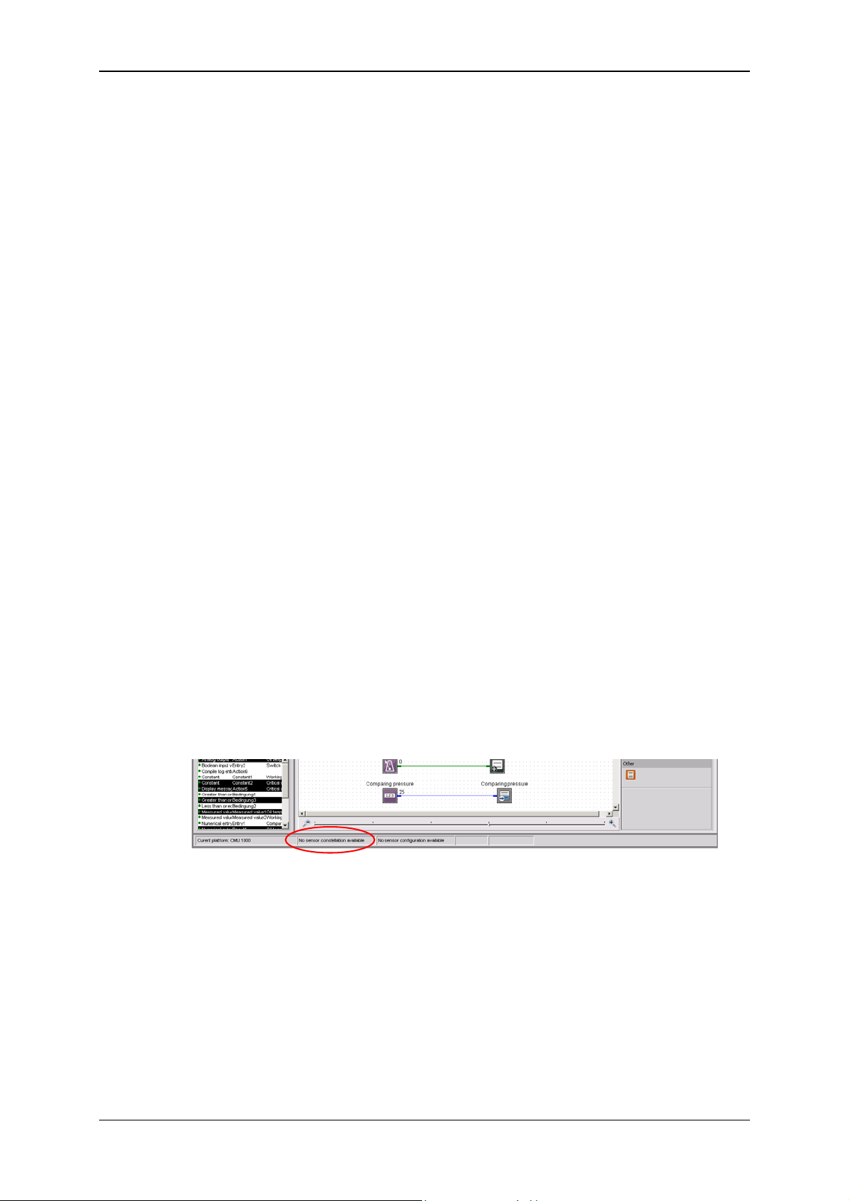
Condition Monitoring Unit CMU 1000 Page 73
6.1.5 Sensor Constellation
Reliable system monitoring requires that it be ensured that precisely the same sensors
are connected during operation as were connected at the time the CMU 1000 was
configured.
The Sensor constellation is used for this purpose. The sensor constellation is a
monitoring instrument for the connected sensor system, i.e. it performs a continuous
comparison between the connected "Actual" sensor system and the specified
"Nominal" sensor system.
The sensor constellation is optional in the CMU 1000 and not mandatory to have. If
however a sensor constellation has been saved, then the connected sensor system
must match it.
When there is an activated sensor constellation, then an accidental, connected
"incorrect" sensor will be recognized, thus preventing a situation in which the CM
program is working with incorrect information.
A sensor constellation can be saved in files and loaded from files, and can be both
received and transferred by the CMU 1000.
The constellation files all have the extension *.hescf.
The sensor constellation contains the following data:
- Quantity of connected sensors
- Quantity of subchannels for each connected sensor
- Status of each individual subchannel (active / inactive)
- Sensor class (Analog / HSI / SMART)
- Units of the individual measured values
- Name of each sensor
- Device designation of each sensor
If a sensor constellation is available in the CM Editor, then you can use the correct
names in connection with the measurements during program generation. It will then be
the case that only those sensors and subchannels that are actually present will be
available and accessible for adjustment.
A status message at the lower edge of the window of the CM Editor indicates whether
or not a sensor constellation is available.
• With the function Apply from file, you can open a saved sensor constellation
file and use it in the CM Editor.
To accomplish this, enter the corresponding path and file name in the window
that opens and then click on Open.
• With the function Apply from device, you transfer one of the sensor
constellations stored in the CMU 1000 to your PC, after which you can use it in
the CM Editor.
Revised 17.12.2009 HYDAC ELECTRONIC GMBH Mat.-No.: 669749
Page 74

Condition Monitoring Unit CMU 1000 Page 74
• With Uninstall you delete the currently available sensor constellation in the CM
Editor, after which it is no longer available for further use when generating
programs.
No saved constellation files are deleted!
• To save a constellation file, select Saving to a file. Enter the respective path
and desired file name for this purpose in the window that opens.
• When the Display function is selected, a window opens in which the complete
sensor constellation is displayed.
Revised 17.12.2009 HYDAC ELECTRONIC GMBH Mat.-No.: 669749
Page 75

Condition Monitoring Unit CMU 1000 Page 75
6.1.6 Sensor Configuration
Sensor configuration is understood to mean all of the input-relevant settings in the
CMU 1000 (Peripherals settings). The sensor configuration can only be generated with
the CMU 1000 itself (offline generation in CMWIN is not possible). All necessary
sensors must be connected in order for this to be possible.
A sensor configuration can be saved in files and loaded from files, and can be both
received and transferred by the CMU 1000.
The configuration files have the extension *.hedcf.
The sensor configuration contains the following data:
- Sensor name
- Mode
- Measurement range
- Decimals
- Units of the individual measured values
A status message at the lower edge of the window of the CM Editor indicates whether
or not a sensor configuration is available.
• With the function Apply from file, you can open a saved sensor configuration
file and use it in the CM Editor.
To accomplish this, enter the corresponding path and file name in the window
that opens and then click on Open.
• With the function Apply from device, you transfer one of the sensor
configuration
stored in the CMU 1000 to your PC, after which you can use it in the CM Editor.
• With Uninstall you delete the currently available sensor constellation in the CM
Editor, after which it is no longer available for further use when generating
programs.
No saved constellation files are deleted!
• To save a configuration file, select Saving to a file. Enter the respective path
and desired file name for this purpose in the window that opens.
Revised 17.12.2009 HYDAC ELECTRONIC GMBH Mat.-No.: 669749
Page 76

Condition Monitoring Unit CMU 1000 Page 76
• When the Display function is selected, a window opens in which the complete
sensor configuration file is displayed.
Note!
With a CM program, one has the opportunity of integrating not only a
configuration file but also a constellation file, so that one can define the
configuration and the constellation at the same time the CM program is
transferred into the CMU 1000. Both parts are however optional and need not
be present in the CM program.
Revised 17.12.2009 HYDAC ELECTRONIC GMBH Mat.-No.: 669749
Page 77

Condition Monitoring Unit CMU 1000 Page 77
6.1.7 Extras
• The following window opens with the function Options is selected:
The selection buttons at the right-hand edge of the window appear after clicking
in the respective selection field.
- In the Language field, you can select between the options of German, English
and French for choosing the CMWIN system language.
- In the field Working folder you define the path for saving the CMWIN files
(CM programs, recordings, constellation and configuration files, ...).
- In the field Name as inscription you define whether or not the respective
function name (e.g. Measured value 2, Action 4) is to be displayed as function
inscription in the "Linked functions" window.
If "No" is selected, then you have the option of entering an inscription text
manually into the function parameters.
- In the field Frame group you define whether or not a frame is to appear
around generated groups in the CM program.
- Clicking on OK applies the settings and returns you to the main CMWIN
window.
Pressing Cancel takes you back without applying any changes.
• By using the Reset Options function you can reset all the modified options and
settings to the standard settings.
• Selecting the Display cycle time function causes the following window to open
and the current cycle time of the CM program to be displayed.
Example:
Revised 17.12.2009 HYDAC ELECTRONIC GMBH Mat.-No.: 669749
Page 78

Condition Monitoring Unit CMU 1000 Page 78
6.2 Window Divisions
The graphics interface of the CM Editor is divided into the following elements:
6.2.1 "Function Properties" Window
The properties of the functions currently selected in the CM program are displayed in
this window. These include:
• Function name (e.g. Action 2; Constant 5; Measured value 12)
• Function type (z.B. Constant, Measured value, Timer)
• Specific properties (parameter settings)
• Comment
6.2.2 "Function List" Window
This window lists all of the functions used in the CM program with the following
specifications:
• Function type (z.B. Constant, Measured value, Timer)
• Function name (e.g. Action 2; Constant 5; Measured value 12)
• Inscription (e.g. Working pressure N.I.O.)
6.2.3 "Linked Functions" Window
This window contains the actual CM program. The display can be zoomed in or out
with the scroll bar on the lower edge of the window.
6.2.4 "Functions" Window
This window contains all of the functions available for program generation, sorted
according to:
• Data sources
• Calculations
• Numerical operations
• Conditions
• Links
• Boolean operations
• Result values/actions
• Other
Revised 17.12.2009 HYDAC ELECTRONIC GMBH Mat.-No.: 669749
Page 79

Condition Monitoring Unit CMU 1000 Page 79
7 CM Program Functions
A CM program consists of many individual functions that are linked with one another
and that are processed and evaluated in cyclical fashion.
7.1 General Information Concerning Functions
A function has Inputs, Outputs and Parameters. This means, for example, the function
"Median value" reads a numerical value at the input, forms a median value above it and
then displays this at the output. A parameter is used to define the amount of time for
which the calculation is rendered.
7.1.1 Inputs / Outputs
For most functions, the outputs change during the running time, depending on the
input. Functions are linked with one another in the Editor. This means, for example,
that the output of a function can be linked with the input of a different function. It is
possible to make one output dependent on several inputs, but not several outputs on
one input.
There are two types of inputs/outputs, depending on the value type: Numerical and
Boolean. A "Boolean output" and only be linked with a "Boolean input" and a numerical
output can only be linked with a "numerical input".
7.1.1.1 Numerical Values
A numerical value is a decimal number, i.e. a numerical value with an optional
algebraic sign and any given number of digits after the decimal point. It is accurate
down to 7-8 significant places. That means that with a value of 2 million (7 places in
front of the decimal point), the addition of a value of 0.001 (3 places after the decimal
point) will not alter the numerical value. One would need accuracy down to at least 10
significant places for it to be altered.
Numerical inputs/outputs and the corresponding connection lines are shown in blue.
7.1.1.2 Boolean Values
A Boolean value is a logical status. There are only 2 statuses: "true" or "1" and false or
"0".
Boolean inputs/outputs and the corresponding connection lines are shown in green.
Revised 17.12.2009 HYDAC ELECTRONIC GMBH Mat.-No.: 669749
Page 80

Condition Monitoring Unit CMU 1000 Page 80
7.1.2 Parameters
Parameters are defined in the Editor and do not change during the running time. An
exception to this are the input parameters, which can be modified in a menu on the
CMU or with a connected PC during the running time.
Parameters have one of the following types:
7.1.2.1 Numerical Parameters
A numerical parameter is a decimal number in accordance with the inputs/outputs.
7.1.2.2 Whole Number
A whole number is a natural number, i.e. it has no digits after the decimal point. As a
rule, no negative numbers are permitted either. Whole numbers are used for example
for numbering purposes.
7.1.2.3 Entry List
An entry from a list is selected for the input list type. The quantity and the type of list
entries is dependent on the respective parameter.
7.1.2.4 Boolean Parameters
A Boolean parameter has, as was already described in connection with the
inputs/outputs, only two logical statuses: "0" and "1". Nevertheless, it is not "0" and "1"
that are set in the Editor, but rather such terms as "No" or "Yes", "Inactive" or "Active",
"Off" or "On", depending on the context.
7.1.2.5 Character String
A character string is an arbitrary text, the length of which is usually limited. In addition,
preceding and subsequent empty spaces are usually removed automatically.
7.1.2.6 Values Table
A values table is a table with several values, whereby each value is positioned in a line
of its own.
Furthermore, it is also possible to enter value pairs. The individual values of a value
pair are then separated from one another with a colon ":".
7.1.2.7 Time
The specification of a time of the day is accomplished in the country-specific format
that is set in Windows.
Revised 17.12.2009 HYDAC ELECTRONIC GMBH Mat.-No.: 669749
Page 81

Condition Monitoring Unit CMU 1000 Page 81
7.2 Data Sources
7.2.1 Numerical Constant
The Numerical Constant function supplies a numerical value which
is defined in the Editor and which does not change during the
Inputs: Outputs: y: (Numerical)
Parameters: p
7.2.2 Measured Value
Inputs: Outputs: y: (Numerical)
Parameters: p
7.2.3 Digital Input
running time.
That means that the Value parameter entered in the Editor is output
during the running time at the output.
: Value (Numerical)
1
The Measured Value function provides the current measured value
of a connected sensor.
The Sensor connection parameter is used to define the sensor; the
channel of the sensor with Subchannel. If a connected sensor has
no subchannel, then no selection is possible at this position.
If a sensor constellation has been saved, then only the active
connections are displayed in the input lists for the Sensor
connection, each of them with the respective sensor name. The
subchannels available for this sensor are then displayed at
Subchannel, each of them with name and unit.
If no sensor constellation is saved, then Ports "A" to "R" are offered
for selection at Sensor connection and the channels "1" bis "32"
a Subchannel.
: Sensor connection (input list)
1
p
: Subchannel (input list)
2
The Digital input function supplies the status of a digital input.
The Input terminal parameter is used to define which digital input
port is used.
Inputs: Outputs: y: (Boolean)
Parameters: p
: Input terminal (input list)
1
Revised 17.12.2009 HYDAC ELECTRONIC GMBH Mat.-No.: 669749
Page 82

Condition Monitoring Unit CMU 1000 Page 82
7.2.4 Numerical Entry
The function Numerical input supplies a numerical value which can
be adjusted in the Parameters menu of the CM device. As an
alternative, it can also be set through a connected PC.
The Inscription parameter is used as a menu option in the input
menu for this purpose. The permissible input range runs from
-2,000,000.000 to +2,000,000.000.
Modifications made in the CM device during the running time also
remain in effect after switch-off. The value that is set under Start
value will used after the first-time transfer of the CM program to the
CM device until the first change is made.
Inputs: Outputs: y: (Numerical)
Parameters: p
: Starting value (Numerical)
1
p
: Inscription (character string)
2
7.2.5 Boolean Entry
The Boolean input function supplies a Boolean value, which can be
set in the Parameters menu of the CM device.
As an alternative, it can also be set through a connected PC.
The Inscription parameter is used as a menu option in the input
menu for this purpose. The input is accomplished on the CM device
by selecting "Yes" or "No".
Modifications made in the CM device during the running time also
remain in effect after switch-off. The value that is set under Start
value will used after the first-time downloading of the CM program
into the CM device until the first change is made.
The Functionality paramter defines how the input is interpreted. The
following settings are possible:
Switch
A menu option is generated on the CM device with which the input
value can be switched on or off. . This functionality is used to active
certain paths in the evaluation logic.
Key
When the value on the CM device is switched on, then only one
impulse is generated in the evaluation logic and the option switches
itself off in the menu again immediately. A key function is simulated,
so to speak. This functionality can be used to trigger events in the
evaluation logic.
Inputs: Outputs: y: (Boolean)
Parameters: p
: Starting value (Boolean)
1
p
: Inscription (character string)
2
p
: Functionality (entry list)
3
Revised 17.12.2009 HYDAC ELECTRONIC GMBH Mat.-No.: 669749
Page 83

Condition Monitoring Unit CMU 1000 Page 83
7.2.6 Time Sensor
The Time sensor is a function which generates an impuls at an
adjustable interval (e.g. every minute, every 5 minutes), thus setting
its Boolean output to "1" for a cycles and then back to "0".
The following settings are possible fo the Interval parameter:
• 1; 2; 5; 10; 15; 30 Seconds,
• 1; 2; 5; 10; 15; 30 Minutes,
• 1; 2; 6; 12; 24 Hours.
The output impulse is thereby always accomplished in synchronized
fashion with the time of day. If, for example, "6 hours" is set, then an
impulse will be generated at 6 AM, 12 AM, 6 PM and 12 PM.
If an impulse is required at particular times of the day, then you
should use a clock timer with a downstream impulse generator
instead of a time sensor (see Chap. 7.2.7).
Inputs: Outputs: y: (Boolean)
Parameters: p
: Interval (input list)
1
7.2.7 Clock Timer
The Clock timer is a function which switches on its Boolean output at
a certain time during a month and then switches it off again at a
different point in time.
The switch-on time is set with the parameters Switch-on day and
Switch-on time, while the switch-off time is set with the parameters
Switch-off day and Switch-off time.
A weekday "Monday" to "Sunday" can be set. The setting "Daily" is
also possible. The "Daily" setting is only possible if both days are set
to "Daily". The Editor prevent erroneous inputs: If, for example, the
switch-on day is changed from "Monday" to "Daily", then the switchoff day is automatically set to "Daily".
If switch-on time and switch-off time are identical, the the output will
be switched on for precisely this specified second.
If only one impulse is required, i.e. if the output in intended to be set
for exactly one cycle to "1" and then back to "0", then use a
downstream impulse generator (see Chap. 7.8.6).
Inputs: Outputs: y: (Boolean);
Parameters: p
: Switch-off day (input list)
1
p
: Switch-off time (time of day)
2
p
: Switch-on day (input list)
3
p
: Switch-on time (time of day)
4
Revised 17.12.2009 HYDAC ELECTRONIC GMBH Mat.-No.: 669749
Page 84

Condition Monitoring Unit CMU 1000 Page 84
7.2.8 Error Event
An error handling can be implemented with the function Error event.
The Boolean output is switched to "1" in the event that an error
condition is present. The output is switched back to "0" if the error
goes away.
The type of error event can be set with the Event parameter.
The following events are possible:
Below signal range
A sensor has cable breakage, for example
Above signal range
One sensor lies above the signal range with its signal
Incorrect sensor constellation
At one sensor connection port there is either no sensor connected,
or an incorrect one.
Numerical error
An error occured during a calculation, e.g. division by 0 or square
root of a negative number, logarithm from 0, etc.
Cycle time exceeded
The set cycle time was exceeded.
Inputs Outputs: y: (Boolean)
Parameters: p
: Event (input list)
1
7.2.9 Boolean Constants
The Boolean Constant function supplies a Boolean value which is
defined in the Editor and which does not change during the running
time. That means that the parameter entered in the Editor is output
during the running time at the output.
Inputs Outputs: y: (Boolean)
Parameters: p
: Value (Boolean)
1
7.2.10 State-bit
The function Show Stat-bit provides the status of the bit defined by
the "Sensor port" and "Bit location" parameters in the status code of
Inputs Outputs: y: (Boolean)
Parameters: p
the selected SMART sensor (status code is sensor-specific) at the
Boolean output.
: Sensor port (Channel A .. Channel H)
1
p
: Bit location (0 .. n -depending on sensor-)
2
Revised 17.12.2009 HYDAC ELECTRONIC GMBH Mat.-No.: 669749
Page 85

Condition Monitoring Unit CMU 1000 Page 85
Additional points for sequency controls in the CMU
The two interrelated function components Sequency and Transition can be used to
implement the functionality of sequency controls or finite state machines.
7.2.11 Sequency
The Sequency component has a numerical output. This represents
the current state of the sequency. At the same time, a number is
Inputs: Outputs: y: (Numerical)
Parameters: -
7.2.12 Transition (in the field "Result values / Actions")
allocated to all states. The term 'sequency' has been taken from
control engineering. Typically several steps are completed one
after the other in a sequency. Branches and backward jumps are
however possible. A sequence can adopt several states which are
numbered in ascending order starting at "0". "0" is always the state
following switch-on. A change in state is always triggered by a
transition.
-
The Transition component serves to bring about a change from one
state to another in a sequency. A transition has a Boolean input
and has 4 parameters.
Inputs: x: (Boolean)
Outputs: Parameters: p
: Sequency
1
Name of the related sequency in the application
program
p
: Current state
2
Number of the state while the input condition is
scrutinized.
With the "ignore" setting, the current sequency state is
ignored, i.e. the input condition is continually
scrutinized, irrespective of the current state of the
sequence.
p
: Successor state
3
• S
tate which is adopted once the input condition occurs.
p
: Dwell time [s]
4
Indicates how many seconds the sequency must be in
the current state before the input condition is
scrutinized for the successor state.
For one sequency, several transitions with identical current and
successor states but with differing input conditions can be used in
the application program. This enables branching into different
sequency cascades within a sequency.
Revised 17.12.2009 HYDAC ELECTRONIC GMBH Mat.-No.: 669749
Page 86

Condition Monitoring Unit CMU 1000 Page 86
7.3 Numerical Calculations
7.3.1 Addition
The Addition function returns the sum of the two input values at the
output:
Inputs x
Outputs: y: (Numerical)
Parameters: -
7.3.2 Subtraction
Inputs x
Outputs: y: (Numerical)
Parameters: -
7.3.3 Multiplication
y = x1 + x
2
: (Numerical)
1
x
: (Numerical)
2
The Subtraction function returns the difference between the two
input values at the output:
y = x1 - x
2
: (Numerical)
1
x
: (Numerical)
2
The Multiplication function returns the product of the two input
values at the output:
y = x1 * x
2
Inputs x
: (Numerical)
1
x
: (Numerical)
2
Outputs: y: (Numerical)
Parameters: -
7.3.4 Division
The Division function returns the quotient of the two input values at
the output:
Inputs: x
Outputs: y: (Numerical)
Parameters: -
y = x1 / x
2
: (Numerical)
1
x
: (Numerical)
2
Revised 17.12.2009 HYDAC ELECTRONIC GMBH Mat.-No.: 669749
Page 87

Condition Monitoring Unit CMU 1000 Page 87
7.3.5 Division Remainder
The Division remainder function returns the division remainder of the
two input values at the output (the modulo). The division remainder
is determined by performing a whole number division x
/ x2 and
1
outputting the remainder of this division as output value.
If the input x1 counts upward, e.g. sequentially by 1, and the input x
amounts to 5, the the output will count around from 0 to 4.
Inputs: x
: (Numerical)
1
x
: (Numerical)
2
Outputs: y: (Numerical)
Parameters: -
7.3.6 Absolute Value
The Absolute value function returns the input value without algebraic
sign at the output:
y = |x|
Inputs: x: (Numerical)
Outputs: y: (Numerical)
Parameters: -
7.3.7 Change of Algebraic Sign
2
The Change of algebraic sign function returns the inverse input
value at the output:
y = -x
Inputs: x: (Numerical)
Outputs: y: (Numerical)
Parameters: -
7.3.8 Rounding
The Rounding function returns the rounded-off input value at the
output. With this function, one can not only round off to whole
Inputs: x: (Numerical)
Outputs: y: (Numerical)
Parameters: p
decimal places, but also to whole-number multiples of a step.
The size of the step will be specified in the Step parameter.
If the step size is 20, for example, then all values between -10 and
10 will be rounded off to 0, all values between 10 and 30 to 20, and
so on.
: Step (Numerical)
1
Revised 17.12.2009 HYDAC ELECTRONIC GMBH Mat.-No.: 669749
Page 88

Condition Monitoring Unit CMU 1000 Page 88
7.3.9 Raising to a Higher Power
The Raising to a higher power function supplies the power of the
input value at the output.
The exponent is set with the Exponent parameter.
Inputs: x: (Numerical)
Outputs: y: (Numerical)
Parameters: p
: Exponent (Numerical)
1
7.3.10 Square Root
The Square root function supplies the square root of the input value
at the output.
If the input value is negative, then the value 0 will be supplied at the
output and an error flag will be set. One can react to this situation
with the Error event function (see Chap. 7.2.8).
If a negative input can occur in everyday practice, then you should
structure the corresponding behavior in accordance with your
preferences with the functions Absolute value, If-then-else and Less
than (see Chap. 7.3.6, 7.4.4 and 7.6.5).
Inputs: x: (Numerical)
Outputs: y: (Numerical)
Parameters: -
7.3.11 Power at Base e
The Power at base e function supples the power at base e at the
output.
The input value is used as the exponent.
Inputs: x: (Numerical)
Outputs: y: (Numerical)
Parameters: -
7.3.12 Natural Logarithm
The Natural logarithm function supplies the logarithm of the input
value at base e at the output.
Inputs: x: (Numerical)
Outputs: y: (Numerical)
Parameters: -
If the input value is negative or 0, then the value 0 will be supplied at
the output and an error flag will be set. One can react to this
situation with the Error event function (see Chap. 7.2.8).
If a negative input can occur in everyday practice, then you should
structure the corresponding behavior in accordance with your
preferences with the functions Absolute value, If-then-else and Less
than (see Chap. 7.3.6, 7.4.4 and 7.6.5).
Revised 17.12.2009 HYDAC ELECTRONIC GMBH Mat.-No.: 669749
Page 89

Condition Monitoring Unit CMU 1000 Page 89
7.3.13 Decade Logarithm
The Decade logarithm function supplies the logarithm of the input
value at base 10 at the output.
If the input value is negative or 0, then the value 0 will be supplied at
the output and an error flag will be set. One can react to this
situation with the Error event function (see Chap. 7.2.8).
If a negative input can occur in everyday practice, then you should
structure the corresponding behavior in accordance with your
preferences with the functions Absolute value, If-then-else and Less
than (see Chap. 7.3.6, 7.4.4 and 7.6.5).
Inputs: x: (Numerical)
Outputs: y: (Numerical)
Parameters: -
7.3.14 Integral
The Integral function supplies the integral of the input value over
time at the output. The output is always calculated with the unit of
Inputs: x
Outputs: y: (Numerical)
Parameters: p
seconds. This means that the input value 6 causes the output to
increase every second by 6. The trapezoidal rule is applied to make
the calculation.
The function still has a Boolean reset input. If the value "1" is
pending there, then the value "0" will be set up at the output.
Furthermore, the integral function also has an automatic anti-wind-
up mechanism. It is with this that a parameterizable Lower limit and
Upper limit are set for the output.
This function adopted from control engineering has the following
background:
If a control variable is not achieved, then the I ratio continues to
integrate further. The controller then may require under certain
circumstances a very long time to exit this range again if the
actuating variable reverses its algebraic sign. This can lead to very
unstable behavior.
: Input value (Numerical)
1
x
: Reset input (Boolean)
2
: Lower limit (Numerical)
1
p
: Upper limit (Numerical)
2
Revised 17.12.2009 HYDAC ELECTRONIC GMBH Mat.-No.: 669749
Page 90

Condition Monitoring Unit CMU 1000 Page 90
7.3.15 Differential Quotient
The Differential quotient function supplies the derivation of the input
value over time at the output. The output is always calculated with
Inputs: x
Outputs: y: (Numerical)
Parameters: p
the unit of seconds. This means that an increase of the input value
from 5 to 6 in one second will yield an output value of 1.
The differential quotient is formed and filtered numerically by the
differential quotient. This filtering is necessary for the following
reasons:
In view of the fact that the input values usually arise from a
quantized measured value, e.g. in connection with the digitization of
an analog quantity, these values will have a so-called quantizing
distortion. This means that the digitization causes the value fluctuate
in terms of resolution. For example, with a 12-bit resolution, a value
of 600 bar that was resolved with 12 bit will fluctuate back and forth
by 0.15 bar. If the differential quotient is formed now every
millisecond, then this quantizing distortion will be amplified by a
factor of 1000. That means that, without filtering, the output would
jump back and forth between + and - 150 bar/s.
The filter can be set with the Filtering parameter. The setting
corresponds thereby to the time range during which the filtering
takes place. Nonetheless, no pure median value formation will be
used as a filter, but rather a special algorithm instead.
The following settings are possible:
• switched off, • 200 ms, • 1 second • 5 seconds.
: (Numerical)
1
: Filtering (entry list)
1
Revised 17.12.2009 HYDAC ELECTRONIC GMBH Mat.-No.: 669749
Page 91

Condition Monitoring Unit CMU 1000 Page 91
7.4 Numerical Operations
7.4.1 Minimum
The Minimum function supplies the smaller of the two input values at
the output.
Inputs: x
Outputs: y: (Numerical)
Parameters: -
7.4.2 Maximum
Inputs: x
Outputs: y: (Numerical)
Parameters: -
7.4.3 Limit
: (Numerical)
1
x
: (Numerical)
2
The Maximum function supplies the larger of the two input values at
the output.
: (Numerical)
1
x
: (Numerical)
2
The Limit function limits the input value x
the output.
The two limits are set by the input values x2 and x3. If x1 is less than
x
, then x2 will be output, if x1 is greater than x3, then x3 will be
2
output, otherwise x
.
1
Inputs: x
1:
x
: Lower limit (Numerical)
2
x
: Upper limit (Numerical)
3
Input value (Numerical)
Outputs: y: (Numerical)
Parameters: -
7.4.4 If - Then - Else
The function If-Then-Else has two numerical inputs x
as a Boolean input x
If the Boolean input value is "1", then the input value of x1 is output
at the output, otherwise the value of x
Inputs x
: (Numerical)
1
x
: (Numerical)
2
x
: (Boolean)
3
Outputs: y: (Numerical)
Parameters: -
.
3
, and makes it available at
1
and x2 as well
1
.
2
Revised 17.12.2009 HYDAC ELECTRONIC GMBH Mat.-No.: 669749
Page 92

Condition Monitoring Unit CMU 1000 Page 92
7.4.5 Median Value
The Median value funtion supplies the arithmetical median value of
the input values over an adjustable time range.
The time range is set in seconds with the Time parameter.
The formation of the median value is accomplished by means of the
"Repeating Average" procedure. This means that, when the time
setting is "2 seconds", for example, the input values are compiled for
2 seconds, then averaged and output at the output. The next median
value interval begins afterwards. The median value remains stopped
at the last median value thereby
Inputs x: Input value (Numerical)
Outputs: y: Median value (Numerical)
Parameters: p
: Time (Numerical)
1
7.4.6 Note Value
The Note value function is used to hold on to certain values (to
freeze them). It has one numerical and one Boolean input.
If the Boolean input value is "1", then the numerical input value is
output at the output. If the Boolean input value is "0", then the last
output value remains in effect.
If the value is only to be applied for one flank of the Boolean input,
then you can put the function Pulse generation upstream from it (see
Chap. 7.8.6).
Inputs x
: Input value (Numerical)
1
x
: Switch value through (Boolean)
2
Outputs: y: (Numerical)
Parameters: -
7.4.7 Note Minimum
The Note minimum function supplies as the output value the
smallest value that the input value has yet reached.
If the input value is greater than the output value, then the output
value remains unchanged. If the input value is less, then the output
value will be reset.
The minimum can be reset with the Boolean input x2. The input
value wil be applied directly at the output for as long as this input is
"1".
Inputs x
: Input value (Numerical)
1
x
: Reset (Boolean)
2
Outputs: y: (Numerical)
Parameters: -
Revised 17.12.2009 HYDAC ELECTRONIC GMBH Mat.-No.: 669749
Page 93

Condition Monitoring Unit CMU 1000 Page 93
7.4.8 Note Maximum
The Note maxi mum function supplies as the output value the largest
value that the input value has yet reached.
If the input value is less than the output value, then the output value
remains unchanged. If the input value is greater, then the output
value will be reset.
The maximum can be reset with the Boolean input x2. The input
value will be applied directly at the output for as long as this input is
"1".
Inputs x
: Input value (Numerical).
1
x
: Reset (Boolean)
2
Outputs: y: (Numerical)
Parameters: -
7.4.9 Tabular Value
With the function Tabular value, the output value is obtained from a
parameterized number table. The input value functions thereby as
Inputs: x: Index of the selected tabular value (Numerical)
Outputs: y: Selected value (Numerical)
Parameters: p
number of the table entry.
If the whole number value of the input is 0 or less, then the first
value of the table will be output; if it is 1, then the second value; and
so on up to the last tabular value. If the input value is greater than
the number of tablular entries, then the last table entry will be output.
As a basic rule, the input value will be rounded off to a whole
number.
The table is defined using the Table parameter. Each value must
have a line of its own at the time of entry. Empty lines are removed
automatically. The number of values will also be defined
automatically on the basis of the available lines. It must be between
2 and 20.
The Tabular value function can be used for example as a
downstream element of a division remainder in order to specify
various values one after the other (see Chap. 7.3.5).
: Table (values table)
1
Revised 17.12.2009 HYDAC ELECTRONIC GMBH Mat.-No.: 669749
Page 94

Condition Monitoring Unit CMU 1000 Page 94
7.4.10 Tabular Index
The Tabular index function is the counterpart to the Tabular value
function. The input value is sorted into a parameterizable numerical
table, which must be organized in order of increasing values, and
the number of the tabular entry is output.
If, for example, the first tabular entry is 4 and the second is 7.8, then
a 0 will be output for all input values less than 0, the value 1 will be
output for all values between 4 and 7.8, and the value 2 for all
values greater than 7.8.
The table is defined using the Table parameter. Each value must
have a line of its own at the time of entry. Empty lines are removed
automatically. The number of values will also be defined
automatically on the basis of the available lines. It must be between
2 and 20.
This function can be used for flexible range definition. Thus, for
example, limit values can be defined in the table when a value is
normal, suspicious, critical and very critical.
Inputs: x: Value in the table (Numerical).
Outputs: y: Index of the value / Value range (Numerical).
Parameters: p
: Table (values table)
1
7.4.11 Characteristic Curve
The Characteristic curve function is used to convert input values
from one range into another. The conversion can be subdivided into
various segments through the specification of up to 20 nodes.
The Table parameter is used to specify the nodes. Each value pair
is in a different line in the table. The values for x and y are separated
by a colorn. The X values must be listed in ascending order. No x
value may appear more than once. Empty lines are removed
automatically. The number of values will also be defined
automatically on the basis of the available lines. It must be between
2 and 20.
The ranges between the nodes are interpolated linearly; the values
outside the nodes are extrapolated from the last segment. A
limitation is easy to set up by simply setting another node nearby
that has the same y value. If for example the range of 0 to 450 is to
be converted to percent and at the same time limited to 0 and 100,
then this is accomplished with the following value pairs:
-1: 0
0: 0
450: 100
451: 100
Inputs: x: X value of the charactertistic curve (Numerical).
Outputs: y: Function value from the charactertistic curve (Numerical)
Parameters: p
: Table (values table)
1
Revised 17.12.2009 HYDAC ELECTRONIC GMBH Mat.-No.: 669749
Page 95

Condition Monitoring Unit CMU 1000 Page 95
7.4.12 Slope
The Slope function is used to prevent rapid value changes. Under
stable conditions, the input value is shown at the output. Changes of
Inputs: x: (Numerical)
Outputs: y: (Numerical)
Parameters: p
the input value are however not passed along directly to the output,
but rather only in small steps. Like a slope, so to speak. Different
slopes can be defined thereby for positive and negative value
modifications.
The parameters Descending slope and Ascending slope are used to
specify the maximum permissible value changes per second.
If for example the value 5 is set for Ascending ramp and the input
value jumps from 0 to 100, then the output will be only slowly
increased, and it will take 20 seconds for the output value to reach
100.
: Descending slope (Numerical)
1
p
: Ascending slope (Numerical)
2
Revised 17.12.2009 HYDAC ELECTRONIC GMBH Mat.-No.: 669749
Page 96

Condition Monitoring Unit CMU 1000 Page 96
7.5 Counting Functions
7.5.1 Count Pulses
The Count pulses function has three Boolean inputs and one
numerical output. If the Counting input has the value "1", then the
Inputs: x
Outputs: y: Count value (Numerical)
Parameters: -
7.5.2 Stop Clock
change from "0" to "1" at the Pulses input will be counted and the
count value will be set at the output. If the Reset input is at "1", then
the count value, and thus the output as well, will be "0".
Flexible counting structures can thus be obtained by placing the
Pulse generation function upstream (see Chap. 7.8.5). The
placement of a downstream Note value function (see Chap. 7.4.6)
makes it possible to also implement a counter with an interim status.
: Pulses (Boolean)
1
x
: Counting (Boolean)
2
x
: Reset (Boolean)
3
The Stop clock function has two Boolean inputs and one numerical
output. If the Start/Stop input has the value "1", then the seconds will
be counted and the time will be set at the output. If the Reset input is
at "1", then the time, and thus the output as well, will be "0".
The behavior at the output can be controlled with the Output
parameter.
Two settings are possible:
Current time
The output value is the current number of seconds counted.
Stopped time
The output value is not the current quantity, but rather the most
recently measured quantity. This means that the current count is set
to the output whenever the time is stopped with the Start/Stop input.
Flexible time measurement structures can thus be obtained by
placing the Pulse generation function upstream (see Chap. 7.8.5).
Inputs: x
: Start/Stop (Boolean)
1
x
: Reset (Boolean)
2
Outputs: y: (Numerical)
Parameters: p
: Output (entry list)
1
Revised 17.12.2009 HYDAC ELECTRONIC GMBH Mat.-No.: 669749
Page 97

Condition Monitoring Unit CMU 1000 Page 97
7.6 Numerical Conditions
7.6.1 Equals
The Equals function compares two numerical input values for
equivalence and outputs a "1" at its Boolean output if the values are
Inputs: x
Outputs: y: (Boolean)
Parameters: p
7.6.2 Does not Equal
equivalent, otherwise a "0".
With the Precision parameter, you can adjust how precise the
comparison is. For this the following explanation:
In view of the fact that numerical values are presented on computers
as floating point numbers with finite precision, normal comparisons
usually fail. Thus, for example, the finite precision of 2/6 is not
necessarily the same as the result of 1/3. The difference is not to be
found before the 8th decimal place, but nonetheless the two values
are not recognized as being equivalent.
The point at which one needs to break off the comparison of
numbers varies from case to case. It is for that reason that you have
the option of controlling the precision of the comparison.
If you specify 0.01 for precision, for example, then the numbers
12.453 and 12.458 will still be recognized as equivalents to one
another, because the difference is less than 0.01.
: (Numerical)
1
x
: (Numerical)
2
: Precision (Numerical)
1
The Does not equal function compares two numerical input values
for equivalence and outputs a "1" at its Boolean output if the values
are not equal, otherwise a "0".
For the Precision parameter, see the explanation in the Equals
function (Chapter 7.6.1).
Inputs: x
: (Numerical)
1
x
: (Numerical)
2
Outputs: y: (Boolean)
Parameters: p
: Precision (Numerical)
1
Revised 17.12.2009 HYDAC ELECTRONIC GMBH Mat.-No.: 669749
Page 98

Condition Monitoring Unit CMU 1000 Page 98
7.6.3 Greater than
The Greater than function compares two numerical input values for
equivalence and outputs a "1" at its Boolean output if value x
greater than x
, otherwise a "0".
2
is
1
In view of the fact that numerical values are presented on computers
as floating point numbers with finite precision, it is difficult to make
decisions in border ranges. (See the explanation in Chapter 7.6.1,
Equals function). This is however usually irrelevant in everyday
usage, because the imprecision is not to be found before the 8th
significant decimal place.
When however it is important that a precise decision be made for a
border range, then you can install the Rounding function upstream
(see Chap. 7.3.8).
Inputs: x
: (Numerical)
1
x
: (Numerical)
2
Outputs: y: (Boolean)
Parameters: -
7.6.4 Greater than or Equal to
The Greater than or equal to function compares two numerical input
values for equivalence and outputs a "1" at its Boolean output if
value x
is greater than or equal to x2, otherwise a "0".
1
For more on the subject of precision, please note the explanations in
the Greater than function (see Chapter 7.6.3).
Inputs: x
: (Numerical)
1
x
: (Numerical)
2
Outputs: y: (Boolean)
Parameters: -
7.6.5 Less than
The Less than function compares two numerical input values for
equivalence and outputs a "1" at its Boolean output if value x
than x
For more on the subject of precision, please note the explanations in
the Greater than function (see Chapter 7.6.3).
Inputs: x
x
Outputs: y: (Boolean)
Parameters: -
, otherwise a "0".
2
: (Numerical)
1
: (Numerical)
2
is less
1
Revised 17.12.2009 HYDAC ELECTRONIC GMBH Mat.-No.: 669749
Page 99

Condition Monitoring Unit CMU 1000 Page 99
7.6.6 Less than or Equal to
The Less than or equal to function compares two numerical input
values for equivalence and outputs a "1" at its Boolean output if
value x
is less than or equal to x2, otherwise a "0".
1
For more on the subject of precision, please note the explanations in
the Greater than function (see Chapter 7.6.3).
Inputs: x
: (Numerical)
1
x
: (Numerical)
2
Outputs: y: (Boolean)
Parameters: -
7.6.7 Within
The Within function compares three numerical input values for
equivalence and outputs a "1" at its Boolean output if value x
greater than or equal to x
, and smaller than or equal to x3,
2
is
1
otherwise a "0".
For more on the subject of precision, please note the explanations in
the Greater than function (see Chapter 7.6.3).
Inputs: x
: (Numerical)
1
x
: (Numerical)
2
x
: (Numerical)
3
Outputs: y: (Boolean)
Parameters: -
7.6.8 Outside
The Outside function compares three numerical input values for
equivalence and outputs a "1" at its Boolean output if value x
smaller than x
or greater than x3, otherwise a "0".
2
For more on the subject of precision, please note the explanations in
the Greater than function (see Chapter 7.6.3).
Inputs: x
: (Numerical)
1
x
: (Numerical)
2
x
: (Numerical)
3
Outputs: y: (Boolean)
Parameters: -
is
1
Revised 17.12.2009 HYDAC ELECTRONIC GMBH Mat.-No.: 669749
Page 100

Condition Monitoring Unit CMU 1000 Page 100
7.7 Boolean Links
7.7.1 Not
The Not function supplies the negated Boolean input value at its
Boolean output.
Inputs: x: (Boolean)
Outputs: y: (Boolean)
Parameters: -
7.7.2 And
Inputs: x
Outputs: y: (Boolean)
Parameters: -
7.7.3 Not - And
I x = "0", then a "1" is output, otherwise a "0".
The And function links the two Boolean inputs with the "and"
operation and supplies the result to its Boolean output.
The output is then "1" only if both inputs are "1", otherwise it is "0".
The following log table makes this function clear.
x
x
1
y
2
0 0 0
0 1 0
1 0 0
1 1 1
: (Boolean)
1
x
: (Boolean)
2
The Not - And function links the two Boolean inputs with the "nand"
operation and supplies the result to its Boolean output.
The output is then "0" only if both inputs are "1", otherwise it is "1".
The following log table makes this function clear.
x
x
1
y
2
0 0 1
0 1 1
1 0 1
1 1 0
Inputs: x
: (Boolean)
1
x
: (Boolean)
2
Outputs: y: (Boolean)
Parameters: -
Revised 17.12.2009 HYDAC ELECTRONIC GMBH Mat.-No.: 669749
 Loading...