

Hycontrol Microflex LR Integral Installation/operation Instruction Manual

Elec. Iss. 04
Hycontrol Limited, Larchwood House, Orchard Street,
Redditch, Worcestershire, UK. B98 7DP
Tel: + 00 44 (0)1527 406800 Fax: +00 44(0)1527 406810
Email: sales@hycontrol.com Web: www.hycontrol.com
May 2013 Rev 04
Microflex LR – Integral
(Ultrasonic Level Measurement)
Installation & Operation
Instruction Manual

INDEX
PAGE
1. GENERAL DESCRIPTION 3
1.1. Microflex LR Integral 4
2. INSTALLATION GUIDE 5
2.1. Installation Position 5
2.2. Installation Dimensions 6
2.3. Installation Wiring 7
2.3.1. MI2 – 2 wire loop powered transmitter 7
2.3.2. MI3 – transmitter with 2 relays and 4-20mA outputs 7
2.3.2.1. MI3 - Terminal Connections for AC supply 7
a. Modulating from User’s External DC Supply (RL to Pos) 7
b. Modulating from User’s External DC Supply (RL to Neg) 8
c. 4 Wire DC – Driving from Internal Isolated Supply (Is) 8
2.3.2.2. MI3 – Terminal Connections for DC Supply 8
a. 4 Wire DC – Driving from Internal Isolated Supply (Is) 8
b. 3 Wire DC – Modulating from Common User Supply (RL to +DC) 8
c. 3 Wire DC – Modulating from Common User Supply (RL to GND) 9
2.4. Hycontrol Link Wiring for Remote diagnostics via GSM 9
3. PROGRAMMING 10
3.1. Entering Data 10
3.2. Access to Main Menu 10
3.3. Entering Basic Data – QUICKSET 11
3.3.1. Flow – Programming 12
3.3.2. Volume 13
3.4. Entering Output Adjustments 13
3.5. Tx Set-up for Gain and Threshold 14
3.6. Diagnostic Display 15
4. GENERAL SPECIFICATION 16
5. PART NUMBER SELECTION 17
6. LABELLING INFORMATION 18
7. MODBUS REGISTER LIST 19 - 22
8. ASSEMBLY OF FLANGE AND CONES 23
APPENDIX A. CROSS TALK PREVENTION 24 - 25
APPENDIX B. APPLICATION TYPES 26 - 27
Microflex LR Integral Transmitter Operating & Installation Manual May 2013 Rev 4
Page 2

USER MANUAL
1.
GENERAL DESCRIPTION
The Microflex LR – Integral Transmitter is capable of non-contact level
measurement over distances of up to 60 metres, depending on the
application. The Integral is an intelligent, system approach to measurement
of solids and liquids with maximum performance combined with a display and
keypad.
The Integral is available with four different transducers for ranges of 10, 20,
40 and 60 metre operation. Each configuration is available as a 2-wire, DC
powered 4-20mA loop (MI2) or 2, 3 and 4 wire DC and AC powered (MI3)
with a combination of Modbus, 2 relays, 4-20mA and PC comms outputs.
The transmitter must be mounted directly above the surface of the material to
be monitored.
Ultrasonic pulses are transmitted to the surface of the material to be
monitored and reflected back to the transmitter. The time period between
transmission and reception of the pulses is directly proportional to the
distance between the transmitter and the material.
Since the speed of sound through air is affected by temperature, a
temperature sensor is integrated into the face of the transmitter to improve
accuracy.
The Integral transmitter is suitable for measuring the following on solids and
liquids:
a) Ullage space or distance to material
b) Material level
c) Volume measurement
d) Material percentage
e) Flow of liquids in open channels
MICROFLEX LR LONG RANGE LEVEL TRANSMITTERS
WARNING
Do not open the transmitter terminal cover or remove
any connection whilst the power is ON.
REFER TO ‘ATEX Safety & Operating Instructions Manual’
IF INSTALLING IN A HAZARDOUS AREA
Microflex LR Integral Transmitter Operating & Installation Manual May 2013 Rev 4
Page 3
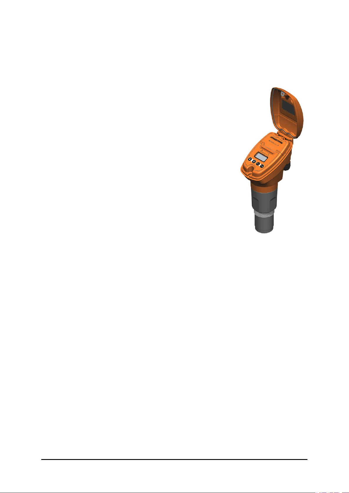
1.1 Microflex LR Integral
The Integral Transmitter is an easy-to-use level
transmitter available with four (4) different high
power, low frequency front ends, capable of reliably
tracking the level of solids and liquids under difficult
conditions, programmed via a 4 button keypad and
an integral menu driven display.
The transmitter is available with a choice of 2 relay
switches, 4-20mA or Modbus outputs; up to 32
instruments can be networked together.
If specified, the instruments are available approved
for ATEX EEx ia Zone 0 gases & Zone 20 dusts
(24Vdc only) or ATEX Dust Protection only, Zone
20.
Remote programming of the product is available via
Hycontrol’s Vision System II software and all the
instruments can be connected via the Hycontrol
Link to a Service Engineer in the Redditch office to
analyse and overcome any problems which may be
experienced in the field, without incurring any
expensive call-out charges.
Microflex LR Integral Transmitter Operating & Installation Manual May 2013 Rev 4
Page 4
2.
INSTALLATION GUIDE
The Integral transmitters are designed to be screwed directly into a flange on a
tank. For long range and dusty applications, the use of a focaliser on the
underside of the flange improves the concentration of the signal and ensures
that spurious signals are eliminated.
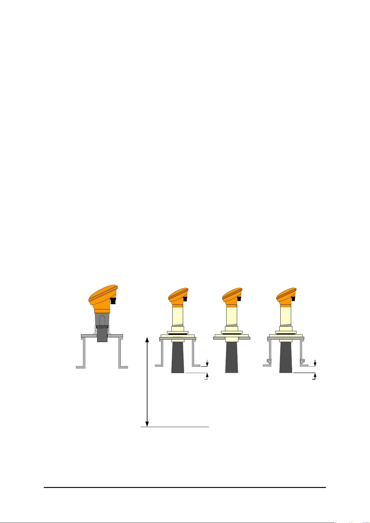
2.1 Installation Position
Ensure that the mounting surface is not subject to vibration and is not in close
proximity to high voltage power cables, contactors or drive controls. The unit
should not be mounted in a confined space where temperature might exceed
the safe working temperature –20°C to + 60°C*. If the unit is mounted outside
it should be protected from direct sunlight or severe weather conditions.
When using a focaliser cone, ensure that it protrudes at least 50mm into the
vessel.
The transmitter must be installed to ensure a clear line of sight from the
radiating face to the product being monitored. Refer to diagrams on Page 6.
Avoid mounting near fill points, ladders, baffles, agitators etc.
Minimum
50mm (2")
NOZZLE
MOUNT
FLUSH
MOUNT
STAND PIPE
MOUNT
Minimum
50mm (2")
‘B’
TOP LEVEL
For ‘B’ blanking – refer to table on page 6.
30KHz 2"
BSP / NPT
MOUNT
*For ATEX temperature classifications see ATEX Safety & Operating Instructions Manual.
Microflex LR Integral Transmitter Operating & Installation Manual May 2013 Rev 4
Page 5
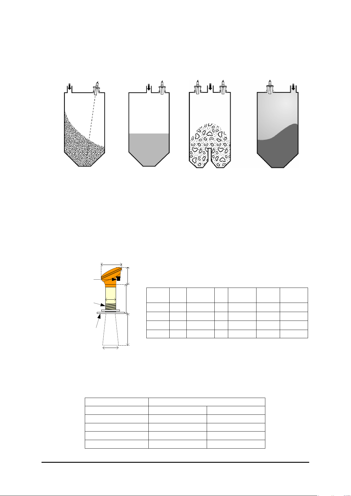
Transmitter Mounting
SOLID (Granular)
LIQUID
DUAL OUTFEED
POWDER
Aim transmitter at
point of outfeed.
Transmitter should be
as perpendicular to
product as practicable.
Use two transmitters and
wire and program as
shown in Appendix A to
avoid cross-talk.
Mount away from
infeed
2.2 Installation Dimensions
MI2 Two wire loop powered transmitter with display and 4-20mA output.
MI3 2, 3 or 4 wire transmitter with display and can have PC Comms,
Modbus and Relay output.
Thread
size
Flange
optional
D
L1
120LC
DC
Optional
160
3 x M16
Conduit
entries
MI2 Two wire transmitter with display
MI3 2, 3 or 4 wire transmitter with display and 2 relays
Range
Metres
L1
LC
Optional
D
DC
Optional
Thread
Size
Flange
Optional
10
177 - 50 - 2”
-
20
255
275
75
98
3”
4”
40
410
413
89
236
3.5”
10”
60
687
460
89
236 - 10”
Flange Options: ANSI, DIN or JIS
Dimensions for 10, 20, 40 & 60 metre range
Ensure that the transmitter face always has the minimum Blanking Distance
above the highest product level in the tank. See table below.
TRANSMITTER
MINIMUM DISTANCE
Minimum
Nominal
MI__10
0.35m (1.2ft)
0.5m (1.6ft)
MI__20
0.5m (1.6ft)
0.8m (2.6 ft)
MI__40
1.0m (3.3ft)
1.3m (4.2 ft)
MI__60
1.2m (4ft)
1.5m (5 ft)
Microflex LR Integral Transmitter Operating & Installation Manual May 2013 Rev 4
Page 6
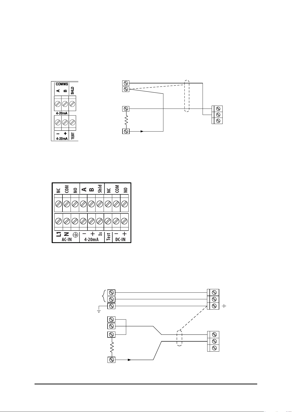
2.3 Installation Wiring
2.3.1 Wiring Diagram – MI2 – 2 wire Loop Powered Transmitter
Terminals
Terminal Connection
+
-
Use
Shielded cable
+
-
User 24V
DC Supply
PLC
DCS
IND
+
-
RL Max 750Ω
4-20mA
TEST
4-20mA
MI2
Terminal
Connection
2.3.2 Wiring Diagram – MI3 – Transmitter with 2 relays & 4-20mA Outputs
Terminals
RL2 COMMS RL1
See Appendix A for ‘Test’ function.
2.3.2.1 MI3 – Terminal Connections for AC Supply
a) Modulating from User’s External DC Supply (RL to Pos.)
4-20mA
+
-
Use
Shielded cable
PLC
DCS
IND
+
-
RL Max 750Ω
Is
4-20mA
MI3
Terminal
Connection
N
L1
AC-IN
User
90 – 260V
AC Supply
+
-
User 24V
DC Supply
NOTE:
RL Max = 750Ω
If user DC Supply 24V
Microflex LR Integral Transmitter Operating & Installation Manual May 2013 Rev 4
Page 7
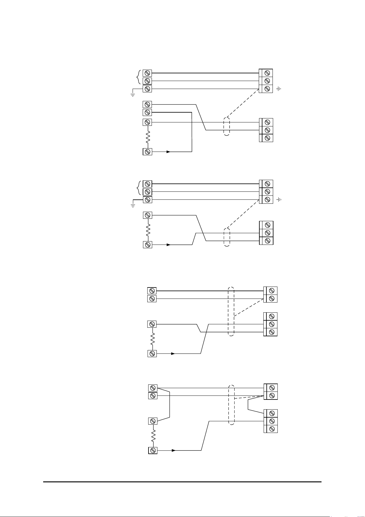
b) Modulating from User’s External DC Supply (RL to Neg.)
+
-
Use
Shielded cable
PLC
DCS
IND
+
-
RL Max 750Ω
4-20mA
Is
4-20mA
MI3
Terminal
Connection
N
L1
AC-IN
User
90 – 260V
AC Supply
+
-
User 24V
DC Supply
NOTE:
RL Max = 750Ω
If user DC Supply 24V
c) 4 Wire DC – Driving from Internal Isolated Supply (Is)
+
-
Use
Shielded cable
PLC
DCS
IND
+
-
RL Max 400Ω
4-20mA
Is
4-20mA
MI3
Terminal
Connection
N
L1
AC-IN
User
90 – 260V
AC Supply
NOTE:
Isolated current output can be
made common with external
DC Supply Positive or
Negative if required
(e.g. RL – connected to GND)
2.3.2.2 MI3 – Terminal Connection for DC Supply
a) 4 Wire DC – Driving from Internal Isolated Supply (Is)
+
-
Use
Shielded cable
+
-
User 24V
DC Supply
PLC
DCS
IND
+
-
RL Max 400Ω
4-20mA
Is
4-20mA
MI3
Terminal
Connection
GND
+DC
DC-IN
NOTE:
Isolated current output can be
made common with +DC or
GND if required
(e.g. RL – connected to GND)
b) 3 Wire DC – Modulating from Common User Supply (RL to +DC)
+
-
Use
Shielded cable
+
-
User 24V
DC Supply
PLC
DCS
IND
+
-
RL Max 750Ω
4-20mA
Is
4-20mA
MI3
Terminal
Connection
GND
+DC
DC-IN
NOTE:
RL Max = 750Ω
If user DC Supply 24V
Microflex LR Integral Transmitter Operating & Installation Manual May 2013 Rev 4
Page 8
c) 3 Wire DC – Modulating from Common User Supply (RL to GND)
+
-
Use
Shielded cable
+
-
User 24V
DC Supply
PLC
DCS
IND
+
-
RL Max 750Ω
4-20mA
Is
4-20mA
MI3
Terminal
Connection
GND
+DC
DC-IN
NOTE:
RL Max = 750Ω
If user DC Supply 24V
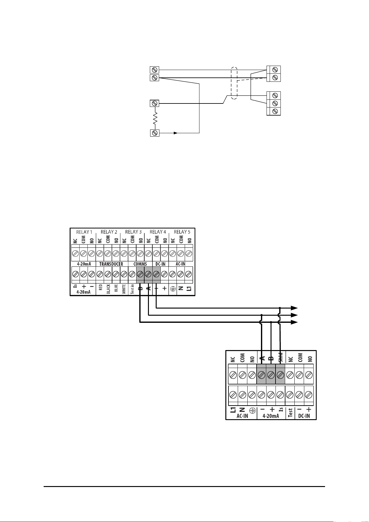
2.4 Hycontrol Link GSM Connection
The Hycontrol Link is a separately powered GSM module which enables
Hycontrol Service Engineers to interrogate and programme any MI3
transmitter.
The following diagram shows how to wire it to the MI3.
Hycontrol Link Terminal
MI3 Series Transmitter
(2 Relays)
To other Microflex LR
and Reflex LR units
Microflex LR Integral Transmitter Operating & Installation Manual May 2013 Rev 4
Page 9
 Loading...