

Page 1
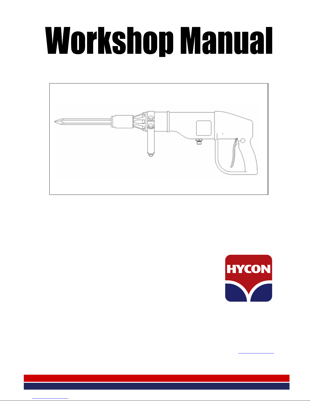
Hydraulic Breaker
HH10 • HH10RV
HYCON A/S
Juelstrupparken 11
DK-9530 Støvring
Denmark
Tel: +45 9647 5200
Fax: +45 9647 5201
Mail [email protected]
www.hycon.dk
Page 2

1
Contents
Page
1. Generally ..................................................................................................... 2
2. Safety Precautions ........................................................................................ 2
3. Dimensions .................................................................................................. 4
4. Technical Data ............................................................................................. 5
5. Maintenance ................................................................................................ 6
6. Testing ........................................................................................................ 6
7. Fault Location .............................................................................................. 7
8. Mounting and Dismounting of Main Components ............................................ 8
9. Repair of Cylinder ........................................................................................ 14
10. Repair of Valve Housing and Trigger Piston .................................................. 15
11. Charging of Accumulator .............................................................................. 19
12. Handle Check .............................................................................................. 21
13. Tool List ..................................................................................................... 22
14. Spare Part Drawings/Lists ............................................................................ 23
Page 3

2
1. Generally
HYCON demolition breakers are designed for long-term operation under difficult
working conditions. All vital components are made of first-class material and have
undergone tempering processes to ensure maximum life. A hydraulic breaker is
produced with small tolerances to obtain an efficient tool with high performance.
However, this makes heavy demands on the manufacture of the tool, and also
requires great care at repair and service work. Be careful not to damage the surface
of the inner components and to keep the hydraulic components clean. It is important
always to observe the tightening torques stated in the repair section.
2. Safety Precautions
• Only use the breaker in accordance with the local working regulations on allowed
working time based on breaker vibration level. Working with the breaker longer
than prescribed may damage the operator.
• In case of horizontal breaking or breaking above the head, always be aware of
material falling down.
• A fine jet of oil at pressure can penetrate the skin. It is therefore important never
to use your fingers to check for oil leaks and never to hold your face close to suspected leaks – use a piece of cardboard instead. If oil has penetrated the skin,
you should get medical treatment immediately.
• Never leave the breaker when connected to the powerpack.
• Always use correct chisel.
• Before connecting the breaker to the power source, always check that the chisel
retainer is in order to prevent the chisel from falling out of the nose part.
• Always use approved hoses. Contact your dealer, if necessary. Mount the hoses
correctly – the plastic cover is marked with ”P” and ”T”.
• The operator must make sure that there are no persons nearby when he starts
breaking. Flying pieces of broken material can cause severe injury.
• The operator must pay extra attention and show caution when working in difficult
working areas, such as slopes and other dangerous nature of the ground. Do not
reach too far with the breaker, but always maintain a good footing and keep your
balance.
• The operator must be properly trained in using the breaker or under supervision
of a qualified instructor.
Page 4

3
• The operator must always use protective goggles, earplugs, hard hat and shoes
when operating the breaker.
• Never use the breaker close to electric cables. Prior to operation, check whether
there are hidden or buried cables in the ground.
• Never wear loose clothing as it may get entangled in the moving parts of the
breaker.
• Inspection or cleaning of the breaker, change of chisel or disconnection of hoses
may never be done while the breaker is connected to the powerpack, as unintentional activation of the breaker can cause severe damage.
• Always connect hoses to the breaker before starting the powerpack. Be sure that
all couplings are tight.
• The breaker may not be operated if the oil temperature is above 70 C°. Operation
at higher temperatures may result in the breaker getting warmer than normal and
the operator risks getting burnt on it.
• To avoid all personal injury and damage to material, all repair, maintenance and
service work must be carried out by authorized or properly trained persons only.
Page 5
4
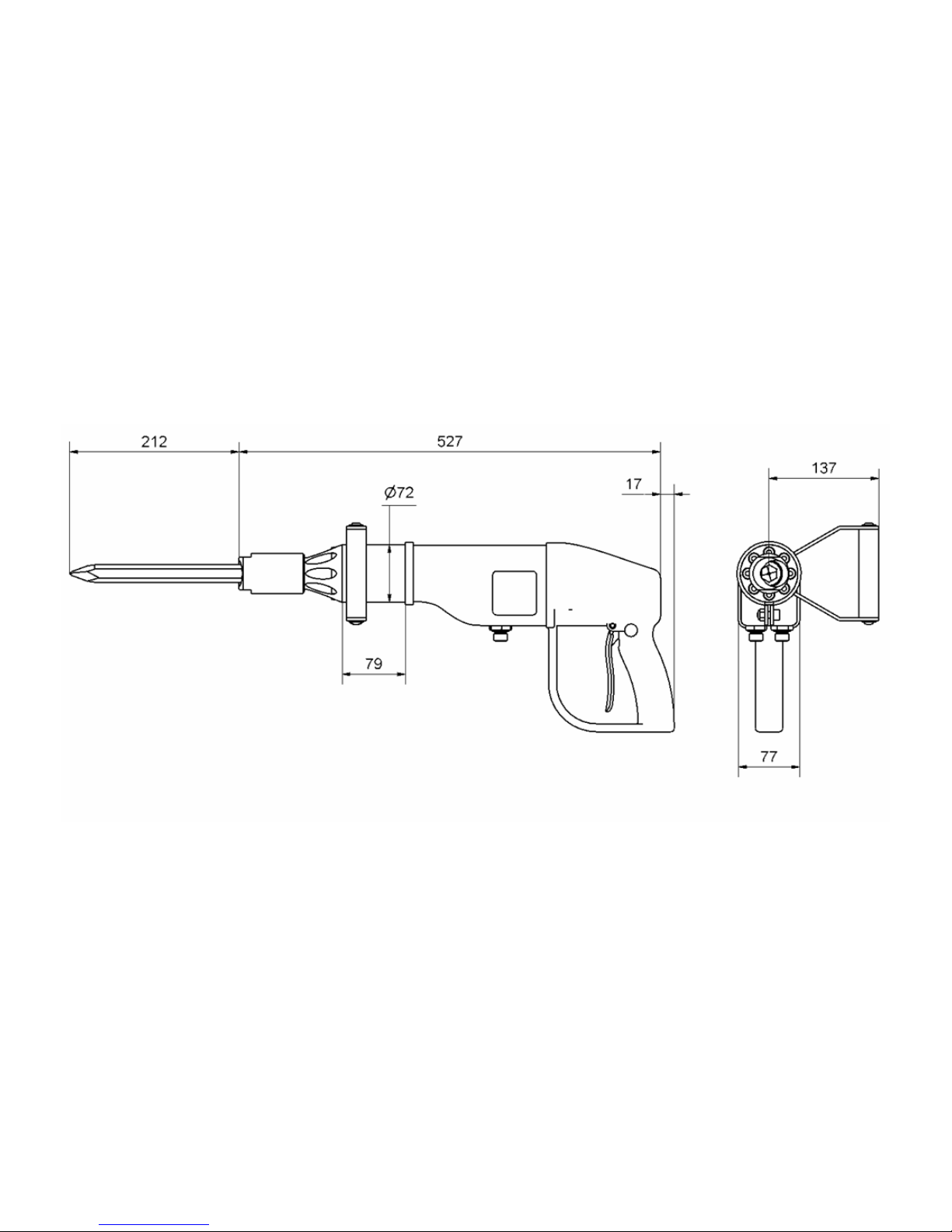
3. Dimensions
Page 6

5
4. Technical Data
Weight breaker 9.9 kg
Service weight incl.
moil point and hoses 12.7 kg
EHTMA category C
Oil flow 20 l.p.m. (5.3 g.p.m.)
Working pressure nominal 100 bar (1450 psi)
Max. setting
pressure relief valve 160 bar (2320 psi)
Max. return pressure 15 bar (220 psi)
Blow frequency 2100 1/min.
Blow energy 22 Joule
Max. oil temperature 70° C
Accumulator charging pressure 40 bar (580 psi)
Cooling capacity needed 2 kW
Vibration level 3 axis (ISO 20643) 9.6 m/s² (140 dB)
Uncertainty (K) 1.4 m/s² (123 dB)
Sound pressure level LPA 1 m 93 dB
Sound power level LWA guaranteed 105 dB
Tool size standard 19x50 mm
Page 7

6
5. Maintenance
Service/Maintenance Daily Weekly Yearly
Check couplings and clean carefully X
Check hoses X
Lock ring in nose part
Check Replace
Check accumulator
X
NB. At service/repair it is important to mount the hoses correctly. The feed line from the
power source must be mounted at “P” and the return line at “T”. “P” and “T” are
marked on the plastic cover.
6. Testing
The breaker should be tested before and after servicing – before servicing to check if
there are certain problems related to the breaker, and after servicing to ensure that the
breaker works satisfactorily. Efficient testing can only be done by means of test equipment
that includes a flow and pressure gauge.
The breaker only works satisfactorily if the return pressure of the power source is not too
high - therefore check this prior to testing the breaker. Mount the test equipment at the
end of the extension hose without the breaker connected. If the test equipment has a flow
valve, it must be fully open during the entire test. Set the power source on “ON”, and
check that the oil flow corresponds to the technical data of the breaker. At this time the
pressure may not exceed 15 bar.
Test the breaker by mounting the test equipment at the pressure hose just before the
breaker. If the test equipment has a flow valve, it must be fully open during the entire
test. Set the power source on “ON” and activate the breaker. Measure oil flow and
working pressure when the breaker has warmed up. The oil flow must correspond to the
technical data of the breaker, and at this oil flow the working pressure of the breaker must
be in accordance with the technical data. A deviation of up to 15 bar is, however, within
normal.
The above measurements and a visual control will ensure a fully functional breaker.
Page 8

7
7. Fault Location
Before you start locating faults, check that the oil flow from the power source is correct
and that the pressure relief valve is set correctly. Follow the instructions in the workshop
manual of the power source.
Problem
Cause
Solution
Breaker does not start, there is
no
pressure in P-hose
Trigger mechanism does not
actuate trigger piston correctly
Replace worn parts in handl
e
See section 12
Breaker does not start, there
is
pressure in P-hose
S
triking piston is stuck in
cylinder
Seizing between cylinder and
striking piston. Polish or
replace components.
Defective Q.R. coupling
Check Q.R. coupling
Oil supply is made to T
-
connection
Switch pump and tank line
Chisel falls out during
operation
Chisel retainer gets loose
during operation
Replace lock ring in chisel
retainer
Chisel bushing or chisel
retainer are worn
Replace parts, see section 8
Wrong chisel size
Check
Bre
aker works irregularly
Impurities in hydraulic oil
Replace oil and oil filter
(see workshop manual of
power source)
Oil level in power source too
low
Add hydraulic oil
Wrong chisel size or worn
chisel bushing
Check
Bad performance
Intern
al leak
Dismo
unt valve housing and
replace O-rings, see section 10
Oil flow from the power source
is not correct for the breaker
Check oil flow
Accumulator pressure too low
Charge with Nitrogen/replace
accumulator, see section 11
Chisel retainer gets loose
Replac
e lock ring in chisel
retainer
Defective Q.R. coupling
Check Q.R. coupling
Return pressure too high
Check power source/hoses
Hose diameter too small
Check hoses
Trigger piston not fully
activated
Replace parts in handle
See section 12
Page 9
8
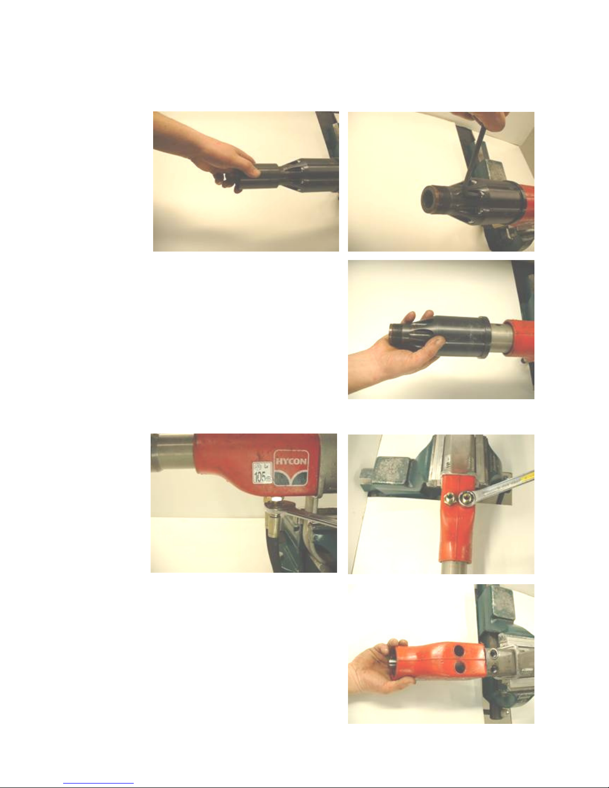
8. Mounting and Dismounting of Main Components
Dismount chisel retainer and nose part.
Dismount tail-hoses, fittings
and plastic cover.
Page 10
9
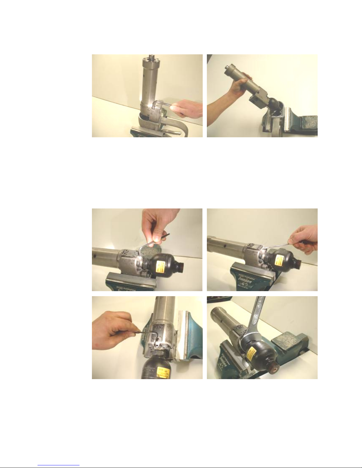
Dismount handle.
Dismount accumulator.
IMPORTANT: There are two screws in the same hole – loosen them carefully.
Page 11
10
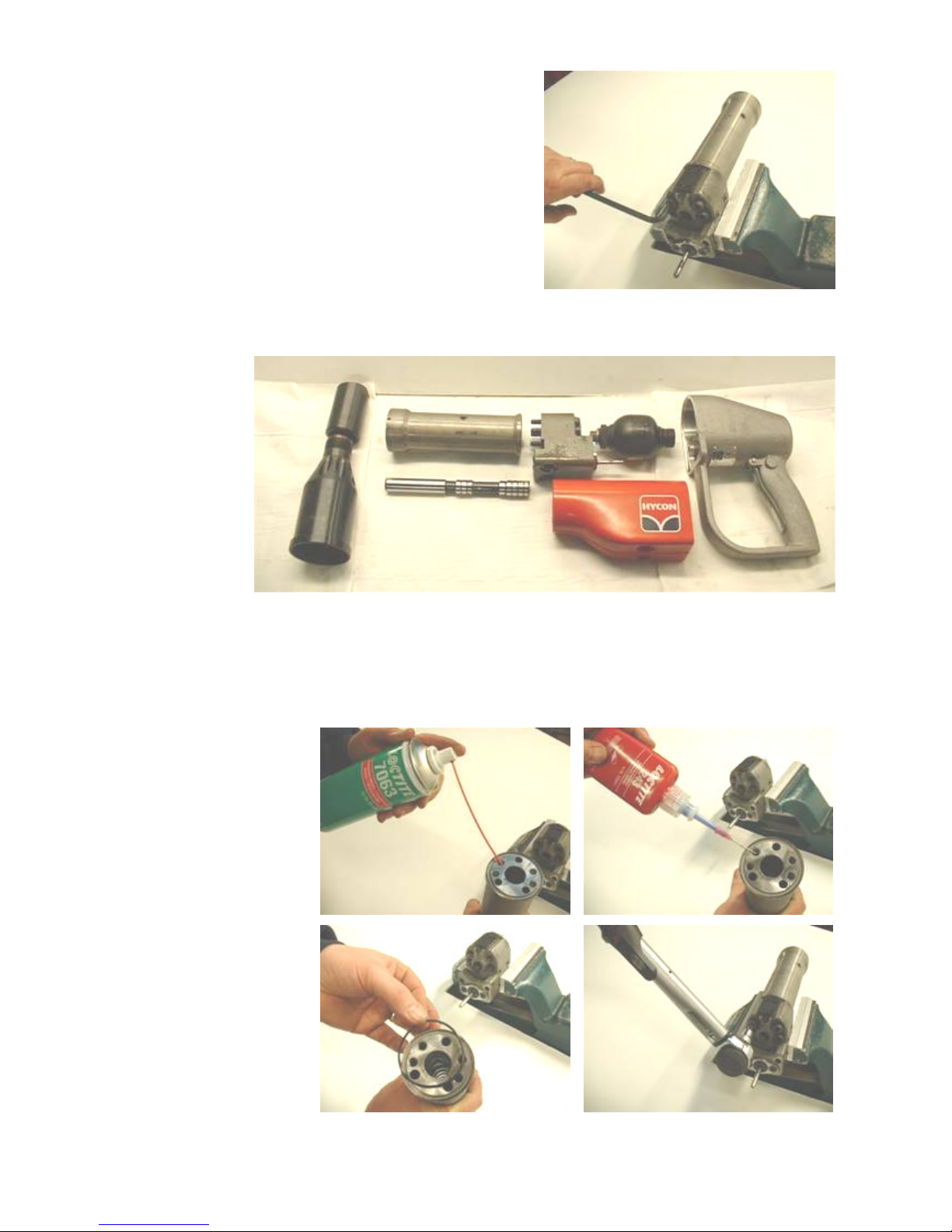
Dismount cylinder.
Main components of HH10 breaker.
Mounting of Main Components
Start by mounting the
cylinder on the valve
block. Make sure to
degrease all parts
carefully with Loctite
7063.
Add a drop of Loctite
243 in the four
threads, and tighten
with a torque of
40 Nm.
Page 12
11
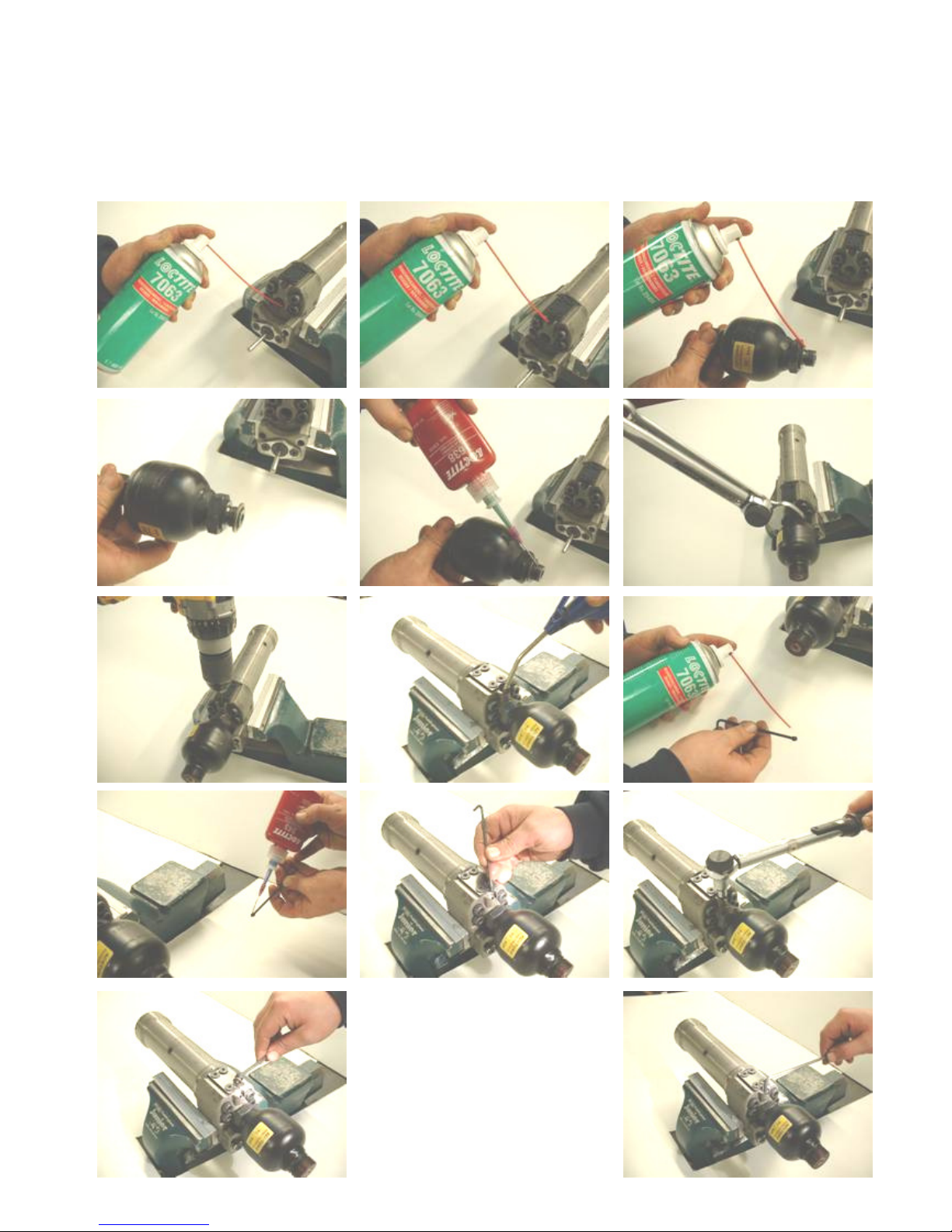
Then mount the accumulator. Clean all threads carefully with Loctite 7063. Mount the seal
ring on the accumulator, and grease the thread with Loctite 638. Tighten the accumulator
with a torque of 90 Nm. Then make a mark by means of a 5 mm drill. Clean the set screw,
add Loctite 243 and tighten it with a torque of 5 Nm. Insert the screw plug and tighten.
Page 13
12
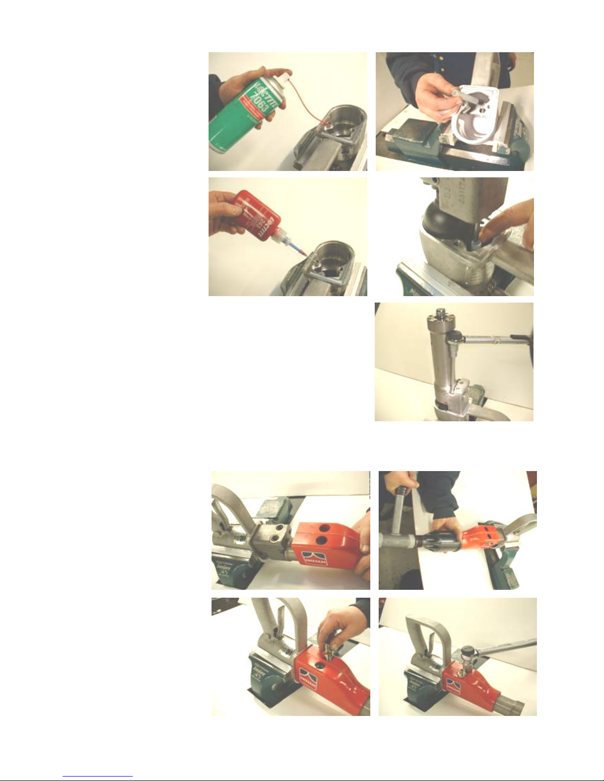
N
ow mount the
handle.
Clean the thread and
screws with Loctite
7063.
Make sure that the
distance piece is
attached to the rod of
the trigger piston.
Tighten the screws
with a torque of
25 Nm.
Then mount the
plastic cover.
Screw in the fittings
and tighten with a
torque of 80 Nm.
Page 14
13
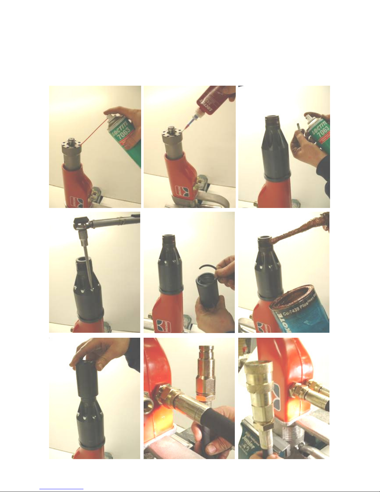
Now mount the nose part. Clean all threads with Loctite 7063, and add Loctite 243 to all
threads. Tighten screws with a torque of 25 Nm. Mount the lock ring on the chisel
retainer. Grease the thread of the nose part with copper paste, and mount the chisel
retainer. Mount tail-hoses. Mount the pressure hose with female coupling at ”P”, and
mount the return hose with male coupling at ”T”.
Page 15
14
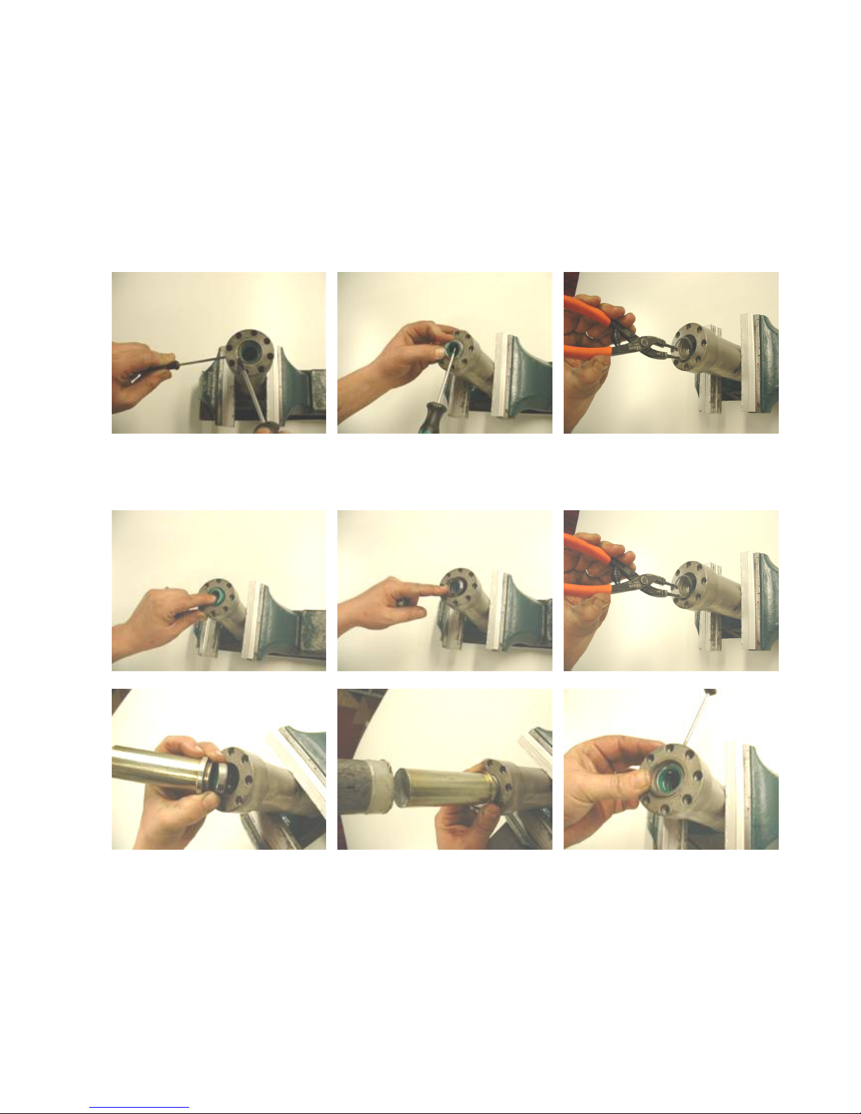
9. Repair of Cylinder
At repair carefully check the inner surface of the cylinder. Visible wearing marks are
acceptable, but they may not be so distinct that you can feel them with a nail. Also check
the cylinder contact surface towards the valve housing for errors.
Dismounting
Mounting
At every repair, replace all seals at the bottom of the cylinder. When mounting a new rod
wiper, use HYCON special tool, part No. 9991775.
Be careful not to damage the surfaces when removing the old seals.
Page 16
15
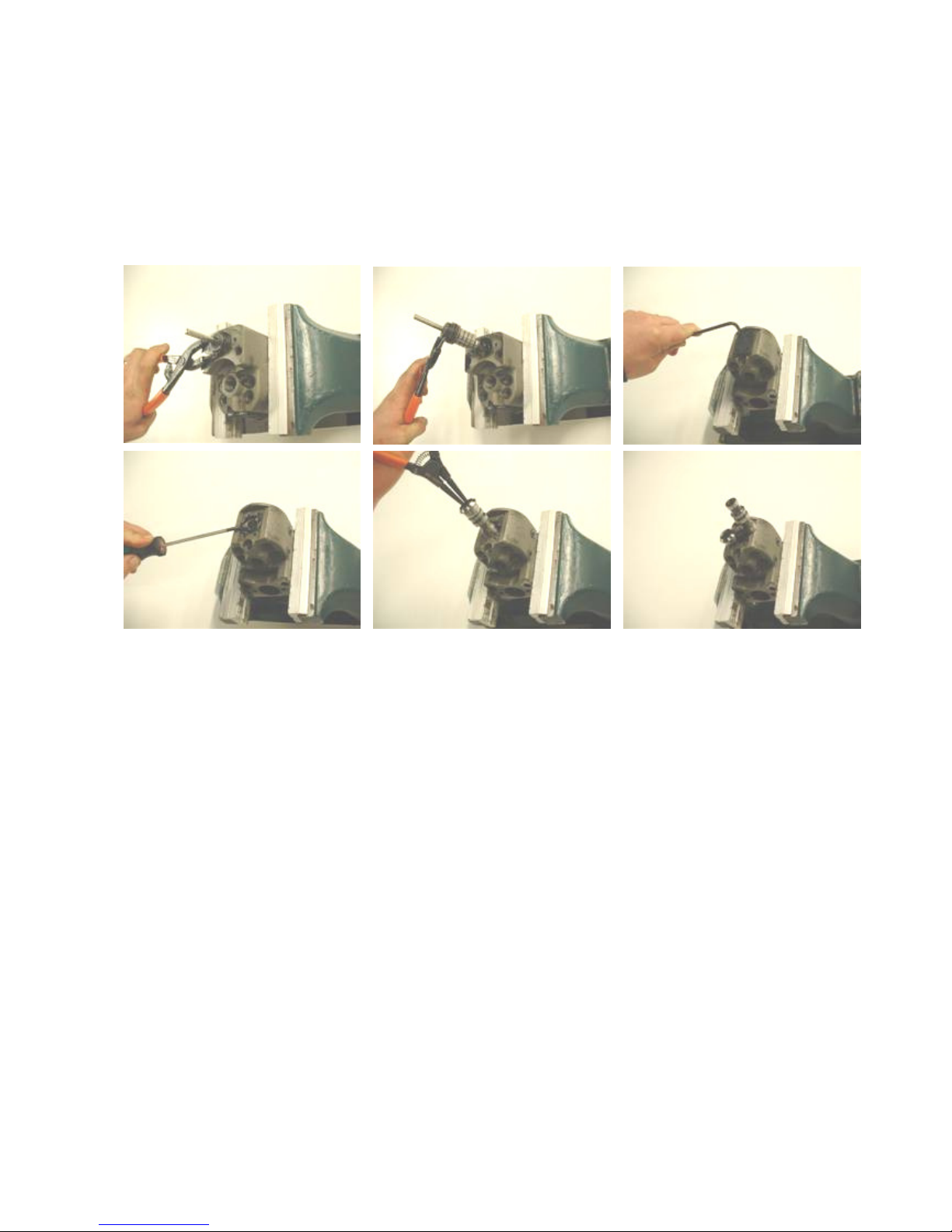
10. Repair of Valve Housing and Trigger Piston
Remove the trigger piston carefully. Then loosen the screws and also remove the spool
carefully.
Dismounting
Page 17
16
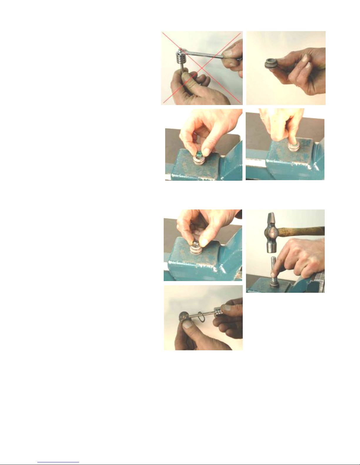
When repairing the trigger piston,
never loosen the piston from the
piston rod. These parts are adapted
to each other and are delivered as
one
spare part.
Visible wearing marks are acceptable, but the surface may not have
scratches you can feel with a nail.
If the breaker is leaking oil around
the trigger rod, replace seals in the
seal housing.
Mount new O-rings first.
Mount new seal. Press the seal into
position with your finger.
Carefully hammer the rod wiper into
position with HYCON special tool
part No. 9991664
When mounting the washer, it is
important to place it correctly. The
plane side of the washer must turn
upwards.
Page 18
17
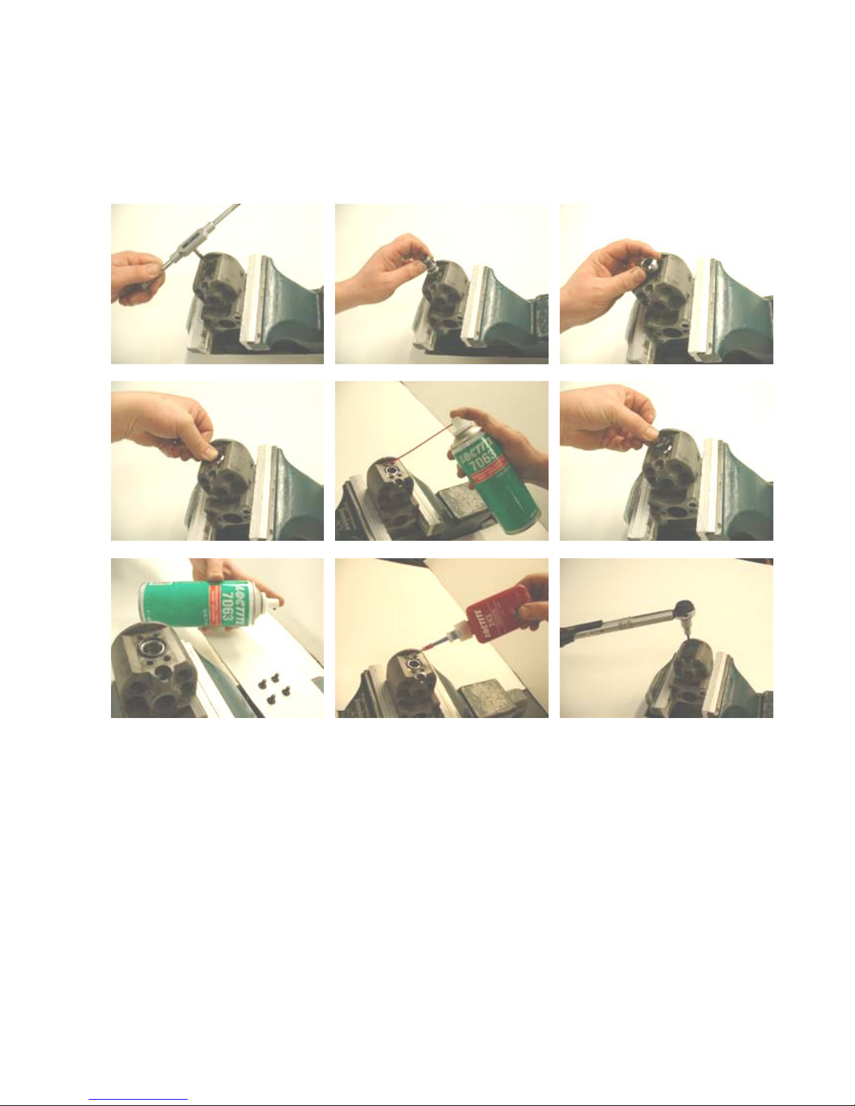
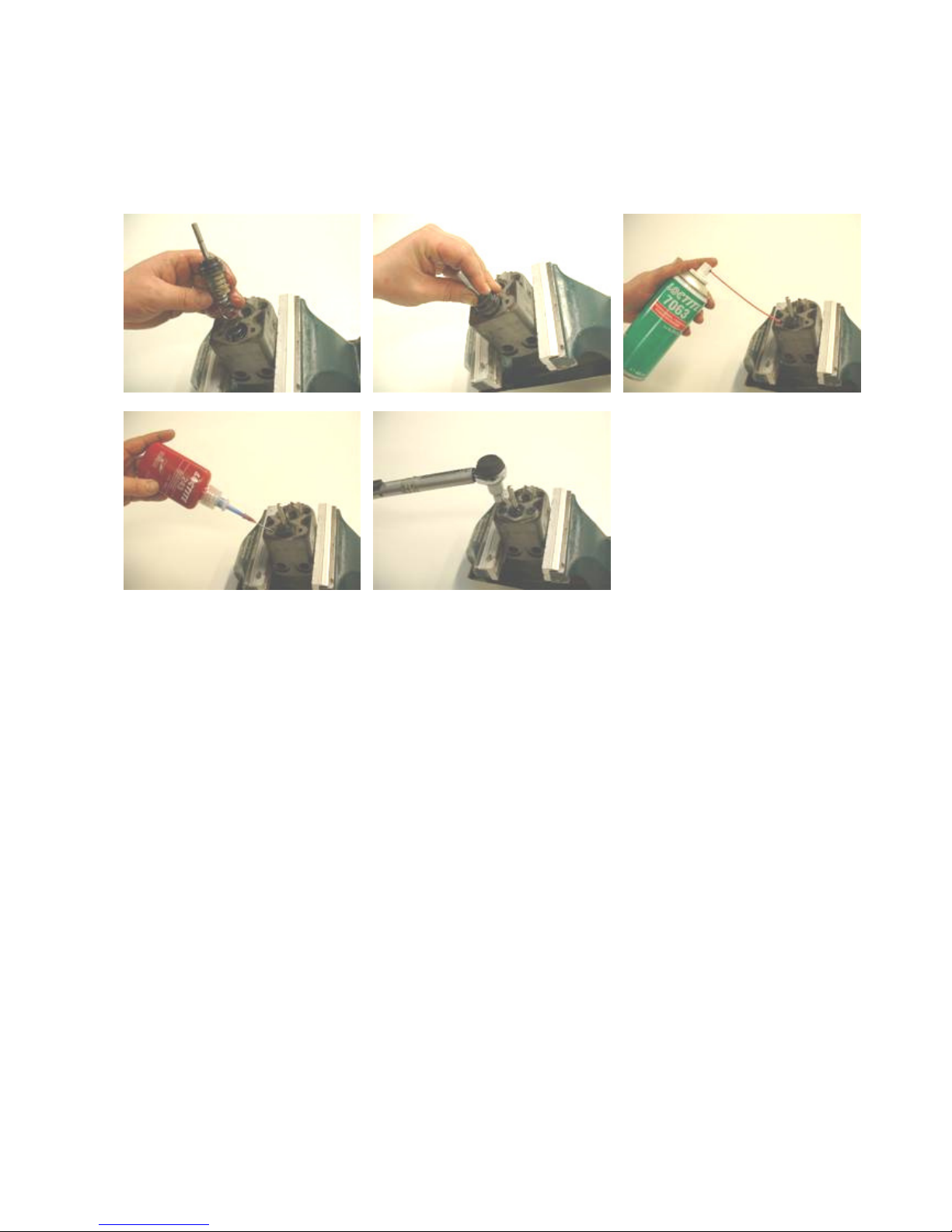
Mounting of Spool
Clean carefully with Loctite 7063 degreaser. If necessary, use an M6 threaded pin to
remove old Loctite. Add Loctite 243 when mounting, and tighten the screws with a torque
of 12.5 Nm.
Page 19
18
Mounting of Trigger Piston
Carefully grease the trigger piston before pushing it in, add Loctite 243 to the two threads,
and tighten the screws with a torque of 12.5 Nm.
Page 20
19
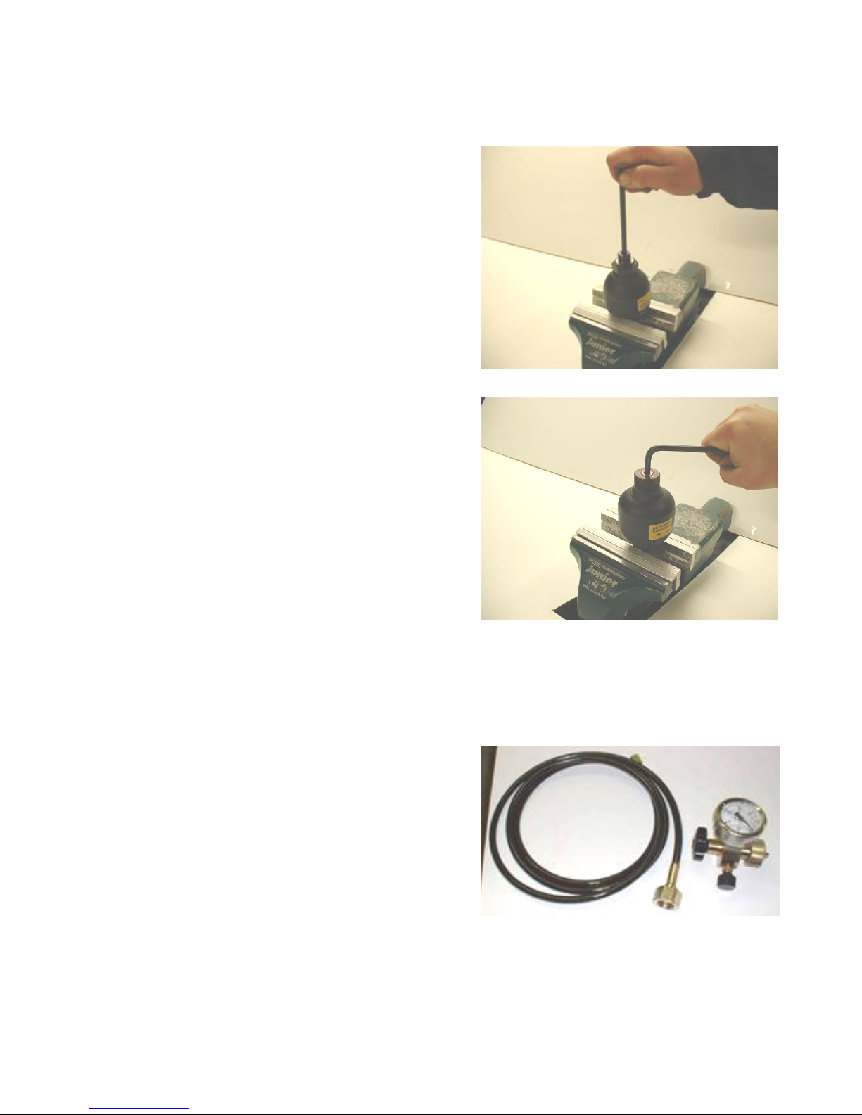
11. Charging of Accumulator
First put a long rod down the hole of the
accumulator to check if the accumulator is
pressurized.
If the diaphragm can be pushed a lot, the
accumulator must be charged with Nitrogen
or the diaphragm is defective.
In case of a defective diaphragm, the
accumulator must be replaced. Loosen the
charging screw.
If the accumulator is in order, you can hear a
clear whistling sound of Nitrogen. In this case
merely recharge the accumulator.
If there is no whistling sound, the diaphragm
is probably damaged and must be replaced.
HYCON filling device part No. 4040061. We can
supply adaptors for other filling devices – both
between bottle and filling device and between
filling device and charging screw. Ask for further
information.
Page 21
20
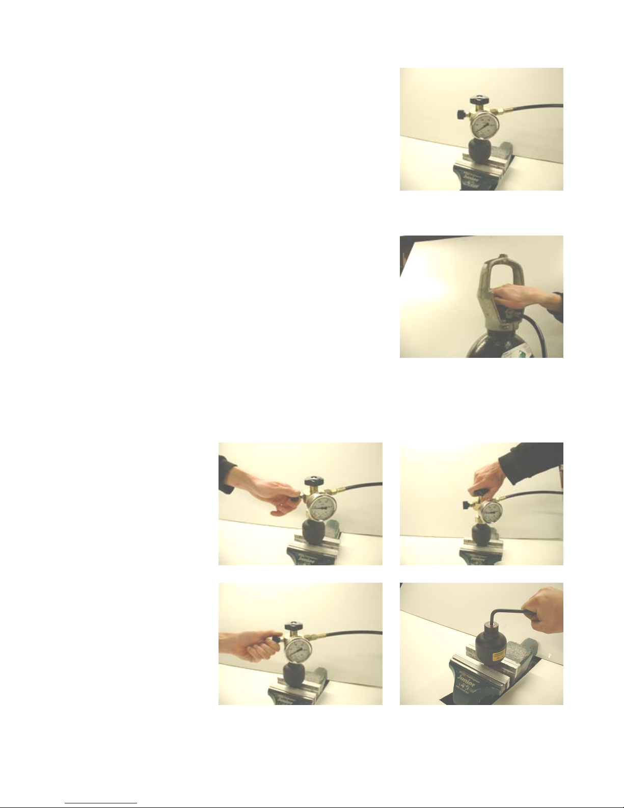
Remove the protective screw on the accumulator
– underneath is the charging screw. Mount the filling
device, and open the charging screw by means of the
handle on top of the filling device.
Important: Always use Nitrogen (N2) to
charge gas accumulators. The use of other
gasses can cause explosion and personal
injury.
Check that the valve on the side of the filling device is
closed, and then carefully turn on the gas until the
pressure gauge shows 60-80 bar.
Close the bottle. Loosen the charging screw by means
of the handle.
Carefully open the valve
on the filling device (A),
and close when the
pressure gauge shows
40 bar.
Tighten the charging
screw by means of the
handle on top of the
filling device (B), and let
out the remaining gas by
opening the valve on the
filling device (C).
Finally remove the filling
device and tighten the
charging screw a little
more to make sure that
the accumulator is
completely tight.
A B
C
Page 22
21
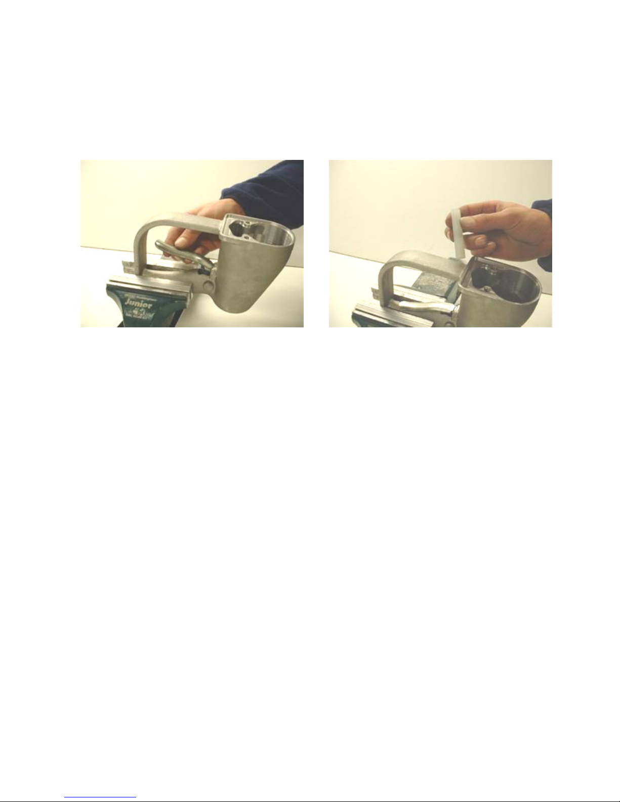
12. Handle Check
Check that the clearance of the trigger lever does not exceed 5 mm. If the clearance is too
big, the cause may be extension of the hole where the trigger lever is mounted due to
wear or wear on the distance piece inside the handle. Replace the parts if they are worn.
Page 23
22
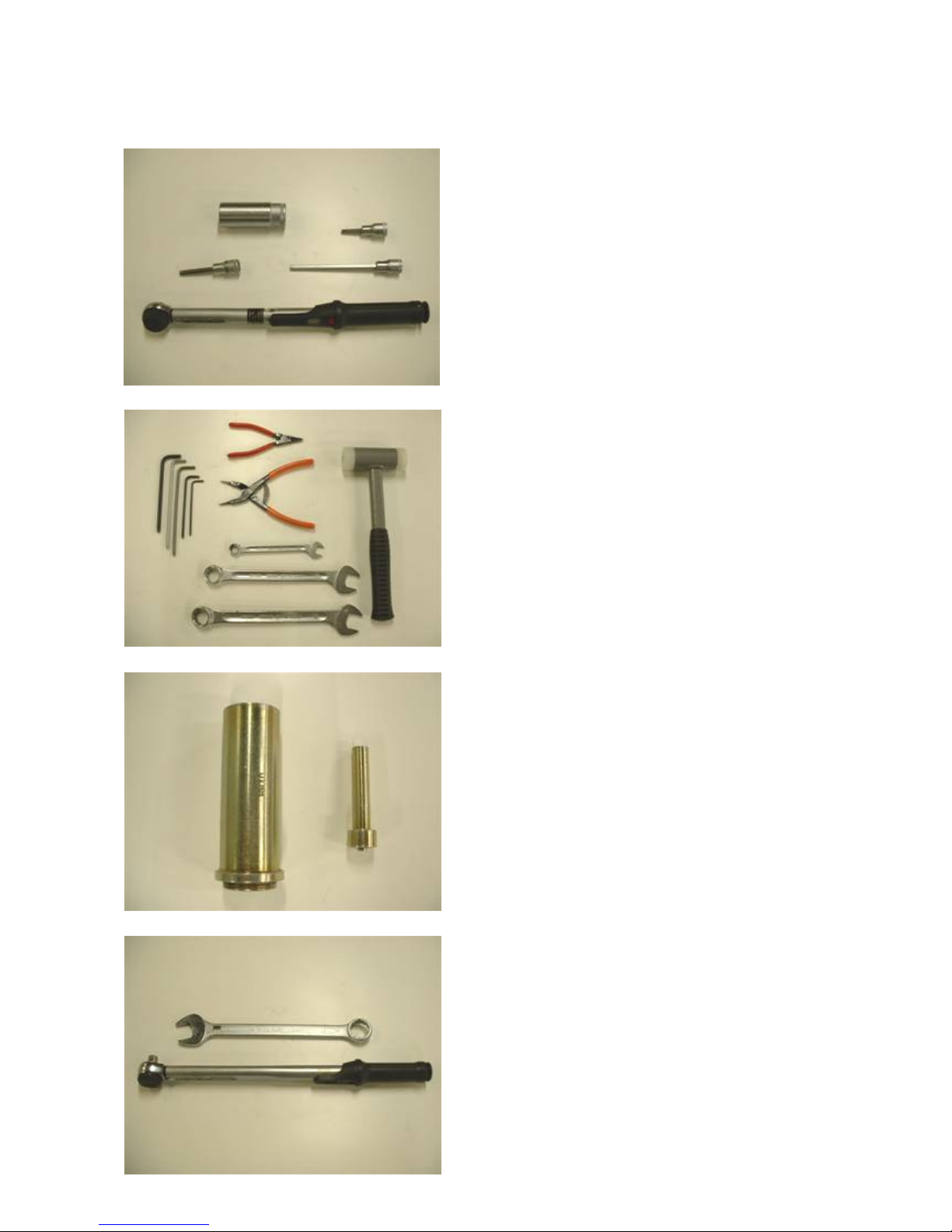
13. Tool List
a. Torque wrench
5-
50 Nm/10
-
100 Nm
b. Hex head socket drivers for torque wrench
sizes 3/16”, 5 mm, 6 mm, long
c. 24 mm socket, long
d. Combination spanners
sizes 13, 22, 24
e. Hex head wrenches
sizes 3 mm, 4 mm, 6 mm, 3/16”
f. Hammer
g. Small external circlip plier
h. Medium internal circlip plier
i. HYCON speci
al tool No.
99916
64
for mounting of rod wiper for trigger piston
j. HYCON special tool No. 9991775
for mounting of rod wiper in cylinder
k. HYCON special
tool No.
9992098
combination spanner size 30 mm
with ½” hole for torque wrench
a
b
c
d
e
f
g
h
i
j
k
 Loading...