

Page 1
Hydraulic
Cut-Off Saw
HCS14 Pro
HCS16 Pro
HCS18 Pro
HYCON A/S
Juelstrupparken 11
DK-9530 Støvring
Denmark
Tel: +45 9647 5200
Fax: +45 9647 5201
Mail: [email protected]
www.hycon.dk
Page 2

1
Contents
Page
1. Safety Precautions ...................................................................................... 2
2. Oil Flow and Pressure.................................................................................. 4
3. Technical Data............................................................................................ 5
4. Dimensions................................................................................................. 6
5. Service and Maintenance............................................................................. 7
6. Testing....................................................................................................... 8
7. Fault Location............................................................................................. 9
8. Dismounting and Mounting of Main Components .........................................10
9. Repair of Handle........................................................................................21
10. Repair of Valve Block ............................................................................... 23
11. Tool List .................................................................................................. 25
12. Spare Part Drawings/Lists......................................................................... 26
Page 3

2
1. Safety Precautions
• Read the cut-off saw and power source operating manuals prior to use.
• Only use the cut-off saw in accordance with the local working regulations on al-
lowed working time.
• Check the oil flow to the cut-off saw. The oil flow may not exceed 30 l.p.m./
172 bar for the 14” version, 40 l.p.m./172 bar for the 16” version, and 34 l.p.m./
172 bar for the 18” version, respectively. Please refer to page 4. A too high oil
flow can result in too high speed on the diamond disc, causing the disc to break.
• Make sure that the diamond disc is mounted correctly and firmly fastened.
• Always use diamond discs approved for handheld cutting and for the material to
be cut.
• Always use discs that are in good condition.
• From the factory, the HYCON cut-off saw is mounted with a safety trigger, which
may never be disturbed or dismounted.
• The cut-off saw has an automatic integrated security that makes the saw stop if
the diamond disc jams. However, in case of jamming, always loosen the disc from
the material, before you start cutting again.
• Start the cut-off saw just before you start cutting, and stop it again once the cut-
ting is done. Do not let the cut-off saw run freely in the air.
• In case of horizontal cutting or cutting above the head, always be aware of mate-
rial falling down.
• A fine jet of oil at pressure can penetrate the skin. It is therefore important never
to use your fingers to check for oil leaks and never to hold your face close to suspected leaks – use a piece of cardboard instead. If oil has penetrated the skin,
you should get medical treatment immediately.
• Never leave the cut-off saw when connected to the powerpack.
• Always use approved hoses. Contact your dealer, if necessary. Mount the hoses
correctly so that the cut-off saw rotates in the right direction.
• The operator must pay extra attention and show caution when working in difficult
working areas, such as slopes and other dangerous nature of the ground. Do not
reach too far with the cut-off saw, but always maintain a good footing and keep
your balance.
• The operator must be properly trained in using the cut-off saw or under super-
vision of a qualified instructor.
Page 4

3
• The operator must always use protective goggles, earplugs, hard hat and shoes
when operating the cut-off saw.
• Never use the cut-off saw close to electric cables. Prior to operation, check
whether there are hidden or buried cables.
• Never wear loose clothing as it may get entangled in the moving parts of the saw.
• Inspection or cleaning of the cut-off saw, change of diamond disc or disconnec-
tion of hoses may never be done while the saw is connected to the powerpack, as
unintentional activation of the saw can cause severe damage.
• Always connect hoses to the cut-off saw before starting the powerpack. Be sure
that all couplings are tight.
• The cut-off saw may not be operated if the oil temperature is above 80 C°. Ope-
ration at higher temperatures may result in the cut-off saw getting warmer than
normal and the operator risks getting burnt on it.
• To avoid all personal injury and damage to material, all repair, maintenance and
service work must be carried out by authorized or properly trained persons only.
• A cut-off saw not in use should always be kept in a safe and dry place.
• Always make sure that the saw labels and warning signs are legible.
• Always use hoses, couplings and spares as such recommend by HYCON A/S.
• Repairs may only be carried out by experienced personnel.
• Make sure that all couplings are cleaned before connection.
• Always disconnect the hydraulic circuit before connecting or disconnecting the
cut-off saw. If this is not done, there is a risk of damage to the quick release
couplings or the hydraulic system getting superheated.
IMPORTAN
T
Page 5

4
2. Oil Flow and Pressure
Your new HYCON cut-off saw is designed for a certain oil flow, working pressure and
maximum pressure. A too high oil flow and/or a too high pressure results in overload
of the cut-off saw, meaning that the lifetime of your new HYCON tool will not be as
expected, and that your service and repair costs will be too high.
It is important to check that the cut-off saw is not supplied with an oil flow beyond
its design capacity, that the working pressure is correct and that the maximum
allowed pressure is not exceeded.
Page 6

5
3. Technical Data
14” Cut-off Saw 16” Cut-off Saw 18” Cut-off Saw
Weight w/o hoses and disc 8.5 kg 9.0 kg 9.4 kg
Oil flow 20-30 l.p.m. 20-40 l.p.m. 20-34 l.p.m.
Working pressure nominal 120 bar 120 bar 120 bar
Pressure relief valve on
power source
Max. 172 bar
Max. 172 bar
Max. 172 bar
Max. return pressure 40 bar 40 bar 40 bar
Max. oil temperature 80° C 80° C 80° C
Number of revolutions 2500-3800 r.p.m. 2000-3800 r.p.m. 2000-3300 r.p.m.
Circumferential speed 46-70 m/s 42-80 m/s 47-80 m/s
Disc size ø350-ø360 mm ø400-ø410 mm ø450-ø460 mm
Arbor size ø25.4 mm ø25.4 mm ø25.4 mm
Cutting depth 137 mm 162 mm 187 mm
Vibration level ‹ 2.5 m/s² ‹ 2.5 m/s² ‹ 2.5 m/s²
Sound pressure level 1 m LPA 92 dB 93 dB 93 dB
Sound power level LWA 103 dB 104 dB 104 dB
Necessary cooling capacity
on power source
1 kW
1 kW
1 kW
Page 7
6
4. Dimensions
Tool Length mm Height mm Width mm Radius mm
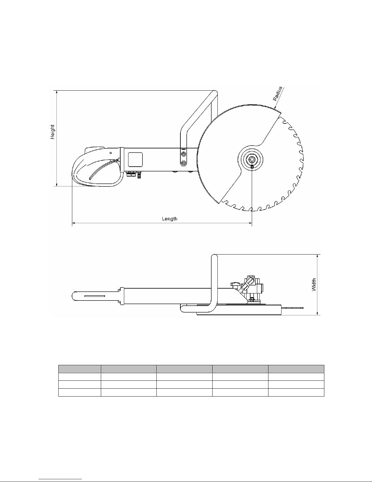
14” saw 600 373 236 188
16” saw 600 373 236 215
18” saw 600 373 236 238
Page 8

7
5. Service and Maintenance
Service/Maintenance Daily Weekly Yearly
Check couplings and clean
carefully
X
Check hoses X
NB. At service/repair it is important to mount the hoses correctly.
Oil Types
The HYCON cut-off saw uses standard hydraulic oil, i.e. all types of mineral oil and
biodegradable oil, which comply with the following values:
Recommended viscosity 20-40 cSt
Permitted viscosity 15-1000 cSt
Viscosity index Min. 100
Temperature area -20° to +70° C
If using biodegradable oil, we recommend the use of oil based on rape. Other types
of oil can be aggressive towards the seals. If you are in doubt, please ask your
dealer.
Page 9

8
6. Testing
The cut-off saw should be tested before and after servicing – before servicing to
check if there are certain problems related to the saw, and after servicing to ensure
that the saw works satisfactorily. Efficient testing can only be done by means of test
equipment that includes a flow and pressure gauge.
The cut-off saw only works satisfactorily if the return pressure of the power source is
not too high - therefore check this prior to testing the saw. Mount the test equipment
at the end of the extension hose without the saw connected. If the test equipment
has a flow valve, it must be fully open during the entire test. Set the power source
on “ON”, and check that the oil flow corresponds to the technical data of the cut-off
saw. At this time the pressure may not exceed 40 bar.
Test the cut-off saw by mounting the test equipment at the pressure hose just
before the saw. If the test equipment has a flow valve, it must be fully open during
the entire test. Set the power source on “ON” and activate the cut-off saw. Measure
oil flow and working pressure when the saw has warmed up. The oil flow must
correspond to the technical data of the saw, and at this oil flow the working pressure
of the saw must be in accordance with the technical data. A deviation of up to 15 bar
is, however, within normal.
The above measurements and a visual control will ensure a fully functional cut-off
saw.
Working Pressure
14” Cut-Off Saw
Free Air
(without cutting)
Cutting
20 l.p.m. 75-85 bar 120–150 bar
30 l.p.m. 85-95 bar 130-155 bar
Working Pressure
16” Cut-Off Saw
Free Air
(without cutting)
Cutting
20 l.p.m. 55-65 bar 90-150 bar
30 l.p.m. 75-85 bar 100-150 bar
40 l.p.m. 95-105 bar 125-160 bar
Working Pressure
18” Cut-Off Saw
Free Air
(without cutting)
Cutting
20 l.p.m. 55-65 bar 90-150 bar
30 l.p.m. 75-85 bar 100-150 bar
Page 10

9
7. Fault Location
Before you start locating faults, check that the oil flow from the power source is
correct, and that the pressure relief valve is set correctly. Follow the instructions in
the workshop manual of the power source.
Problem Cause Solution
Saw does not start, there is
no
pressure in P-hose
Trigger mechanism does not
actuate trigger piston
correctly
Trigger mechanism is stuck
in valve block
Replace worn parts in handle
See section 9
Dismount trigger from valve
block, and clean or replace
parts
See section 8
Defective Q.R. coupling Check Q.R. coupling Saw does not start, there is
pressure in P-hose
Oil supply is made to
T-connection
Switch pump and tank line
Safety trigger does not work Spring is too slack Replace spring, see section 9
Impurities in hydraulic oil Replace oil and oil filter (see
workshop manual of power
source)
Saw works irregularly
Oil level in power source too
low
Add hydraulic oil
Internal leak Dismount valve housing and
replace O-rings, see section 10
Oil flow from the power
source is not correct for the
saw
Check oil flow
Defective Q.R. coupling Check Q.R. coupling
Return pressure too high Check power source/hoses
Hose diameter too small Check hoses
Bad performance
Trigger piston not fully
activated
Replace worn parts in handle
See section 9
Page 11
10
8. Dismounting and Mounting of Main Components
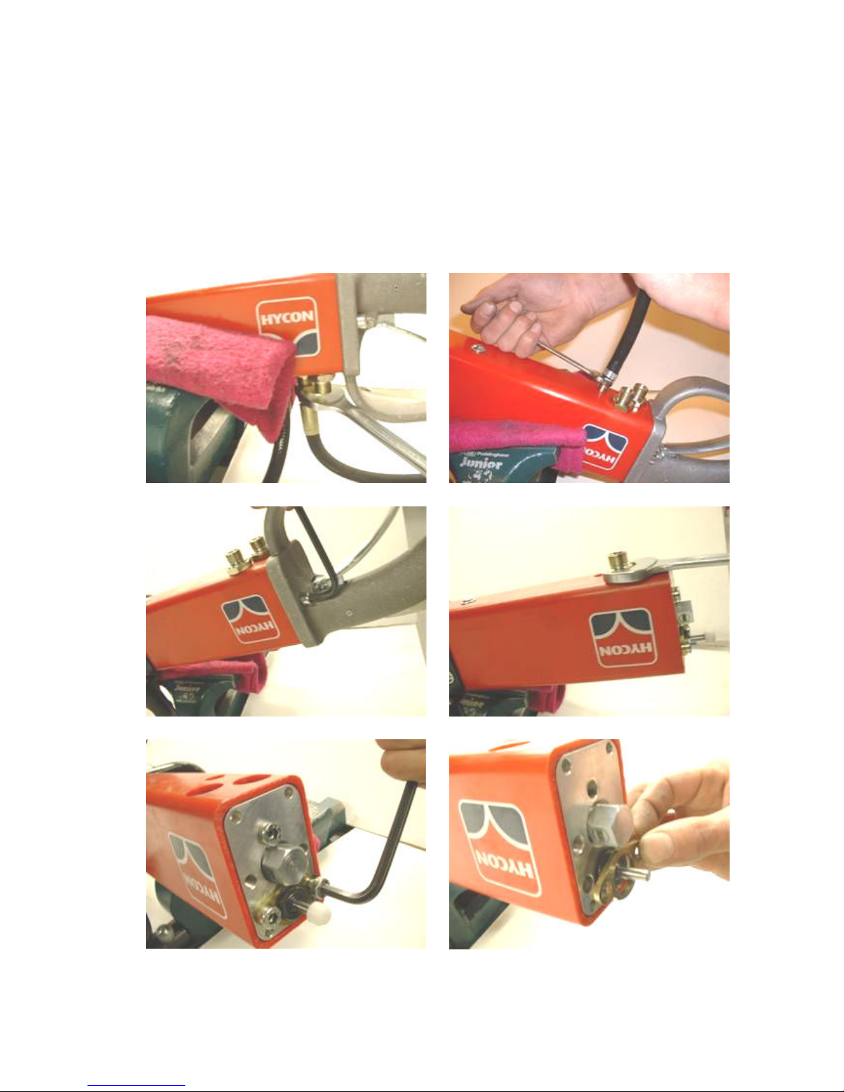
Dismount tail-hoses (place the cut-off saw with the hoses pointing downwards, as oil
will come out when the hoses are disconnected).
Dismount the water hose. Then loosen the two screws on the handle, and carefully
pull off the handle. Dismount the two fittings and unscrew the three screws going
through the valve block. The bracket for the trigger piston can now be removed.
Page 12
11
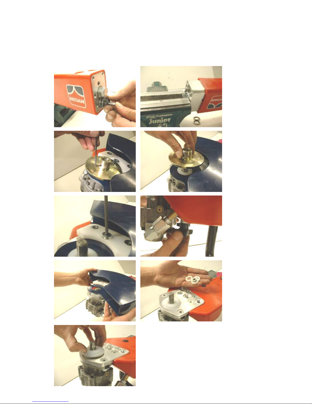
Now carefully remove the trigger piston. Fix the valve block in a vice and pull off the
plastic cover. This way there will be no damage on the valve block.
Dismount the set screw from the adaptor for the disc and remove the adaptor.
Unscrew the screw with hole (for water supply). Dismount the two star knobs, and
remove the guard. Dismount the four washers and the distance pipe.
Page 13
12
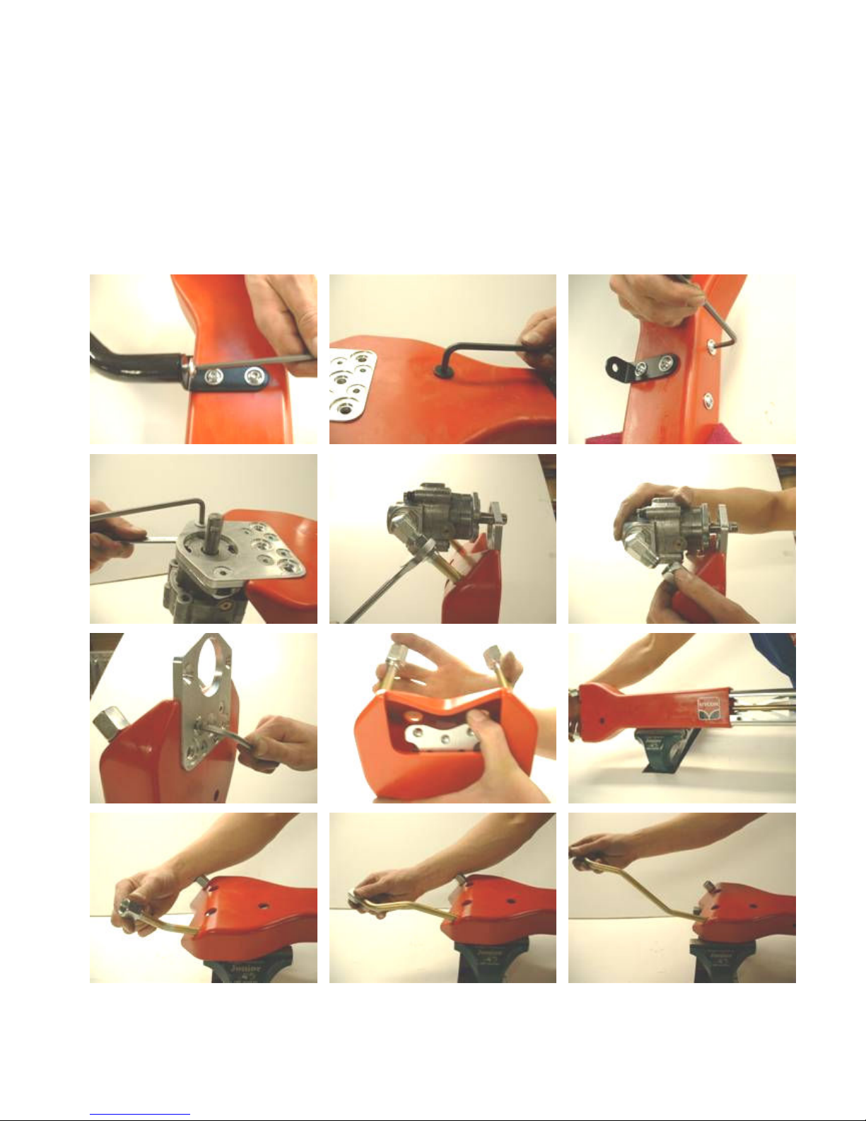
Remove the two screws that fix the front handle. Then dismount the four screws in
the plastic cover. Dismount the screws that fix the motor to the motor plate, and
then loosen the nuts on the elbow fittings between pipes and motor. Now remove
the motor. Unscrew the four screws on the motor plate and push the steel frame out
of the plastic cover.
To be able to pull the steel frame fully out of the plastic cover, it is necessary to
adjust the pipes. Twist the pipes while pulling them out of the cover.
Page 14
13
Hydraulic Cut-Off Saw – Main Components
Mounting of Main Components
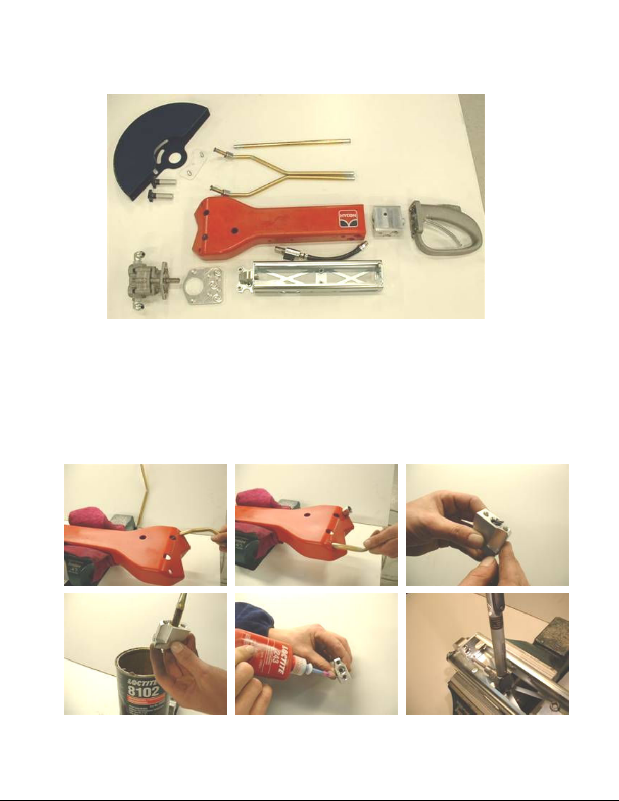
Start by inserting the pipes in the plastic cover (twist them while pushing them into
position). Insert the O-ring in the angle plate and grease. Add Loctite 243 to the two
threads, and mount the angle plate on the steel frame. Tighten the screws with a
torque of 20 Nm.
Page 15
14
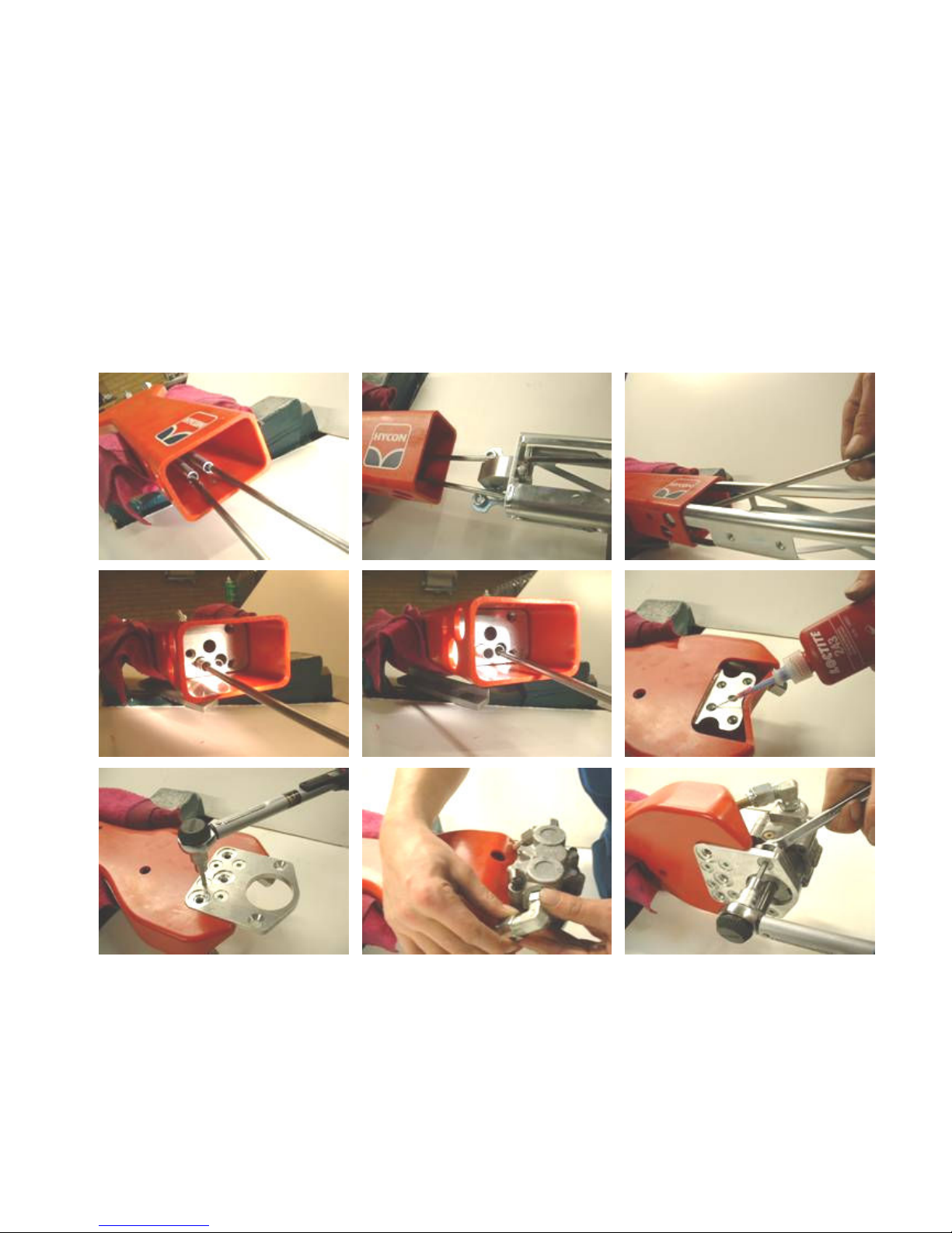
For mounting the steel frame you need two steel bars (HYCON special tool No.
9992079) to be inserted in the pipes. Pull the pipes away from each other and push
in the steel frame in between. Push the frame a little into the plastic cover, pull out
the steel bars, and then push the frame completely into the cover. Again use the
steel bars to catch the pipes inside the plastic cover, and push out the two pipes
through the steel frame.
Add Loctite 243 to the four threads and mount the motor plate. Tighten the screws
with a torque of 20 Nm. Place the motor on the motor plate and tighten the nuts on
the elbow fittings by hand. Mount the two screws with lock nuts through the motor
plate and the motor. Tighten the screws with a torque of 20 Nm.
Page 16
15
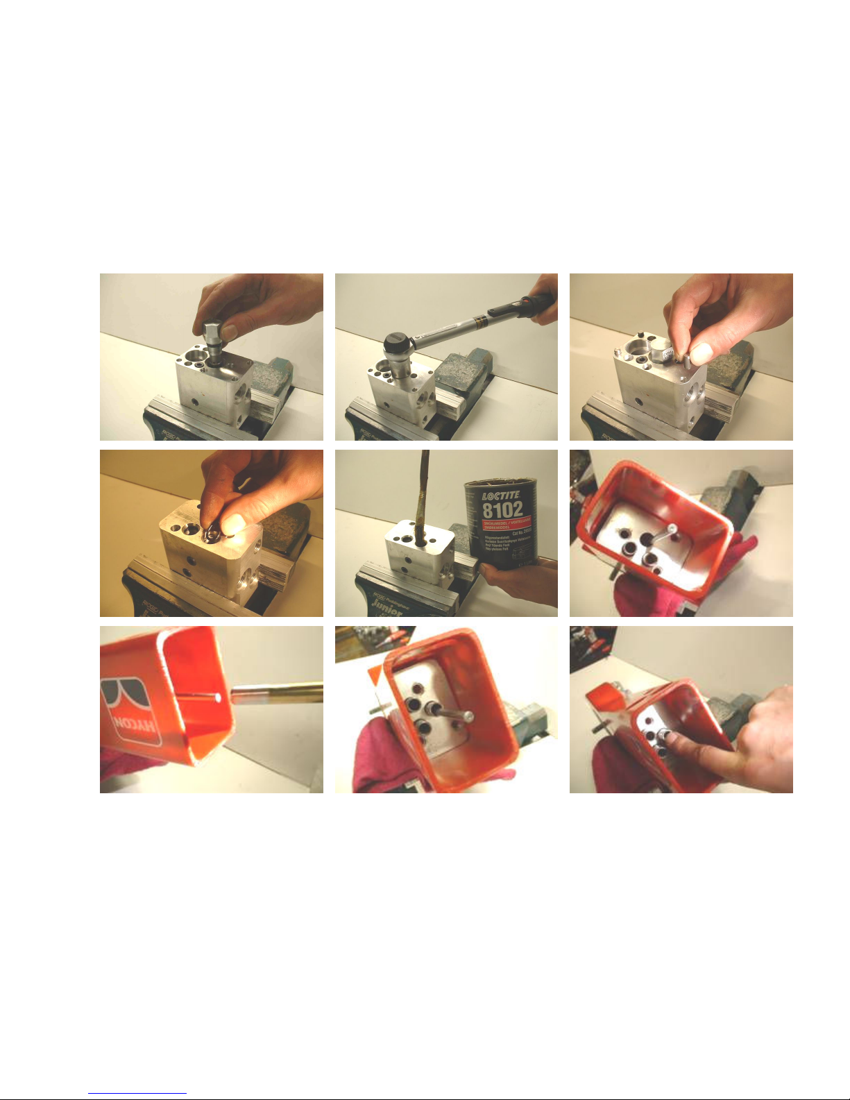
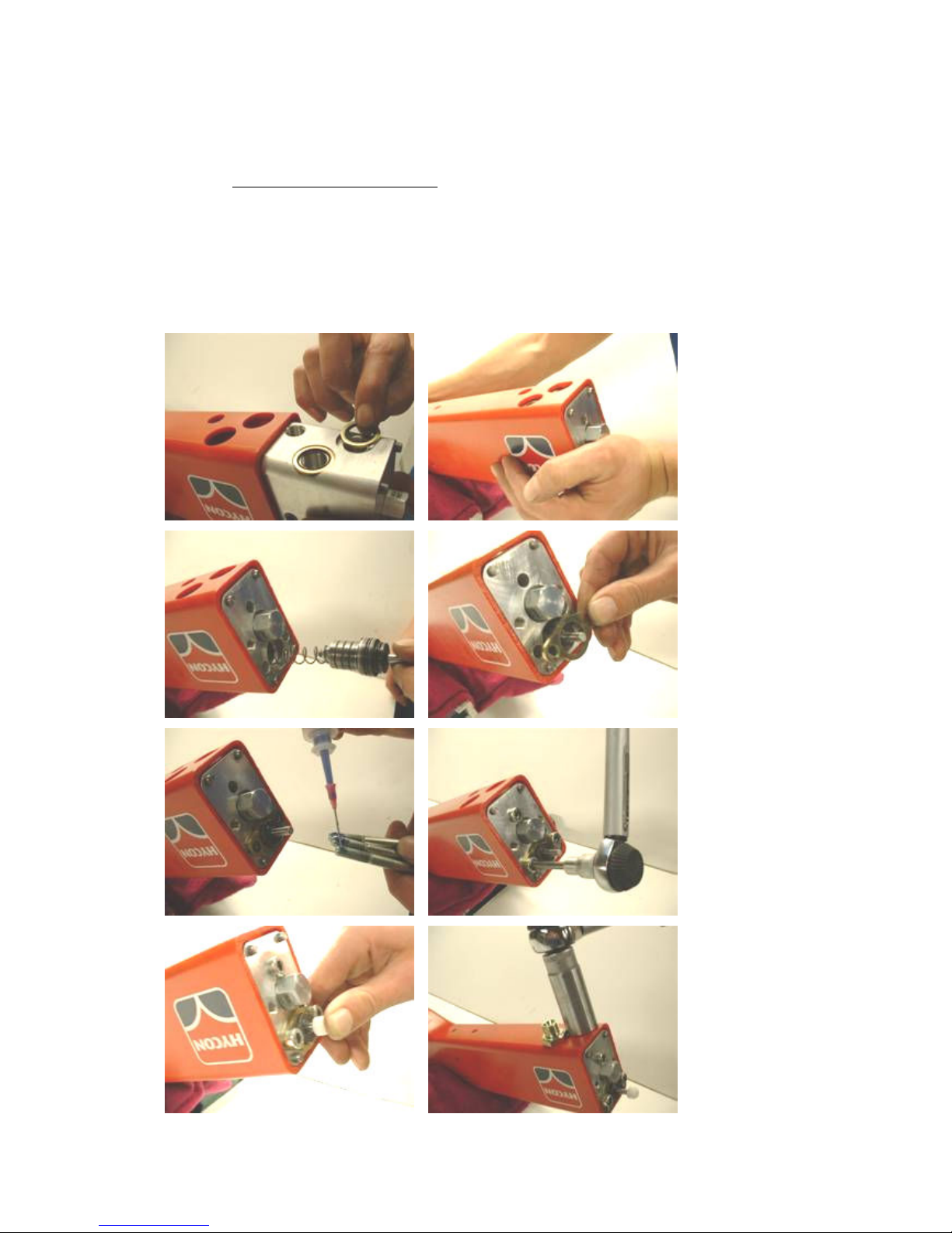
Mount the check valve in the valve block, and tighten with a torque of 40 Nm. Place
the four cylinder pins in the corner holes. Place O-rings in the three holes and
grease. To mount the water pipe, you need a steel bar (HYCON special tool No.
9992079). Insert the steel bar through the steel frame and down in the hole at the
bottom of the frame. Then insert the water pipe over the steel bar and push it into
position. Remove the steel bar. Push the water pipe again to make sure that it is
placed correctly at the bottom of the frame.
Page 17
16
Push the valve block into the plastic cover (place the two seal rings in the valve block
before pushing it in). It is very important to push the valve block very carefully into
the plastic cover in order not to damage the three O-rings on the inner side of the
valve block when they are pushed down over the pipes. When dismounting the cutoff saw, always replace the O-rings.
Carefully push in the trigger piston and mount the bracket for the trigger piston. Add
Loctite 243 to the three screws and tighten with a torque of 20 Nm. Mount the
distance piece on the trigger rod (check the distance piece for wear, replace if too
worn). Push in the trigger rod (trigger piston should move smoothly). Now mount the
two fittings and tighten with a torque of 50 Nm.
Page 18
17
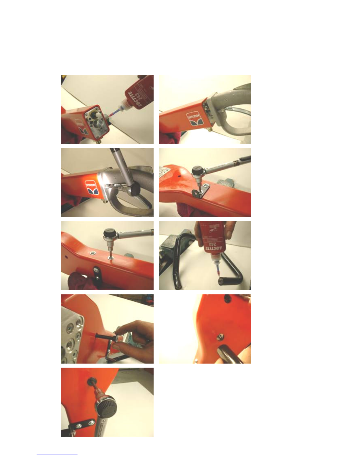
Add Loctite 243 to the two threads in the valve block, and mount the handle. Tighten
the two screws with a torque of 20 Nm. Now mount the bracket for the front handle
and the screws in the plastic cover. Tighten all four screws with a torque of 15 Nm.
Add Loctite 243 to the thread on the front handle, and tighten the two screws with a
torque of 15 Nm.
Page 19
18
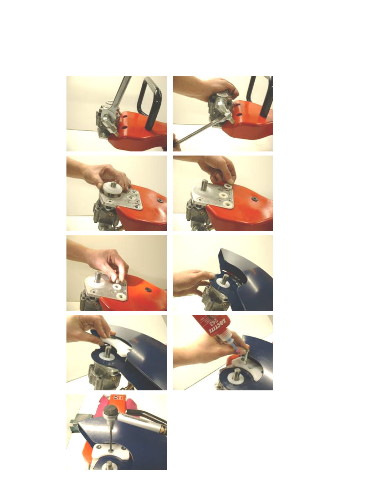
Now tighten the nuts on the elbow fittings between motor and pipes. Place the four
washers and the small distance pipe in the motor plate. Mount the cover and the
retainer plate. Add Loctite to the thread for the screw with hole (for water supply),
mount the screw, and tighten with a torque of 8 Nm.
Page 20
19
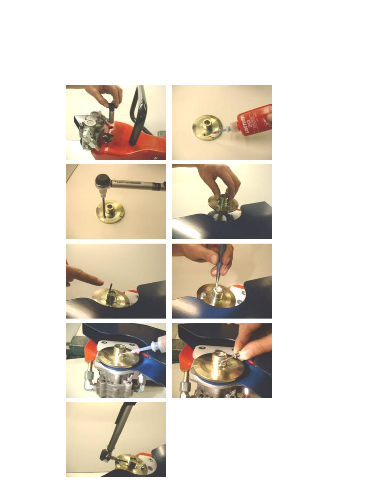
Mount the two star knobs. Add Loctite 243 to the thread in the adaptor, and tighten
the screw with a torque of 15 Nm. Push the adaptor down over the motor shaft, and
carefully tap the shaft key into position. Make two centre punch marks on each side
of the keyway to prevent the shaft key from slipping out. Add Loctite 243 to the
small thread in the adaptor and mount the set screw. Tighten with a torque of 3 Nm.
Page 21
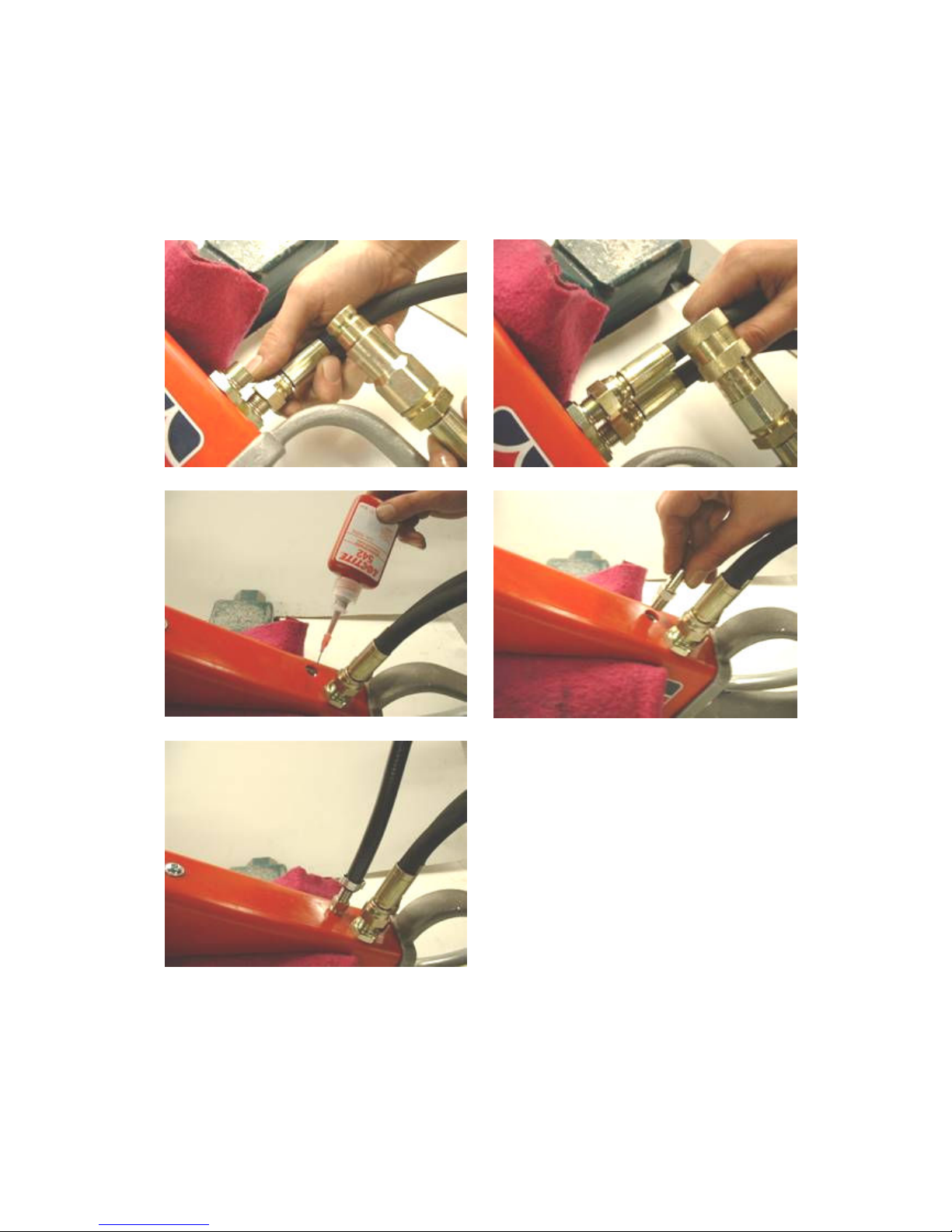
20
Finally mount the tail-hoses. Mount the return hose with male coupling a “T” and the
pressure hose with female coupling at “P”. Add Loctite 542 to the thread and mount
the nipple for the water hose. Mount the water hose. Mount the water hose and fix it
with the hose clamp.
Page 22
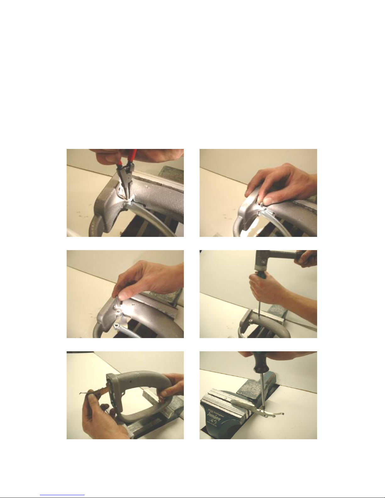
21
9. Repair of Handle
Dismounting
Start by checking the trigger lever for clearance. Replace the worn parts, if clearance
is too big.
Remove the two retaining rings from the pin, and push out the pin. Dismount the
trigger lever. Hammer out the pin for the safety trigger by means of a drift or a
screwdriver (the pin cannot be used again). Now remove the safety trigger.
Dismount the two screws that fix the leaf spring to the safety trigger.
Page 23
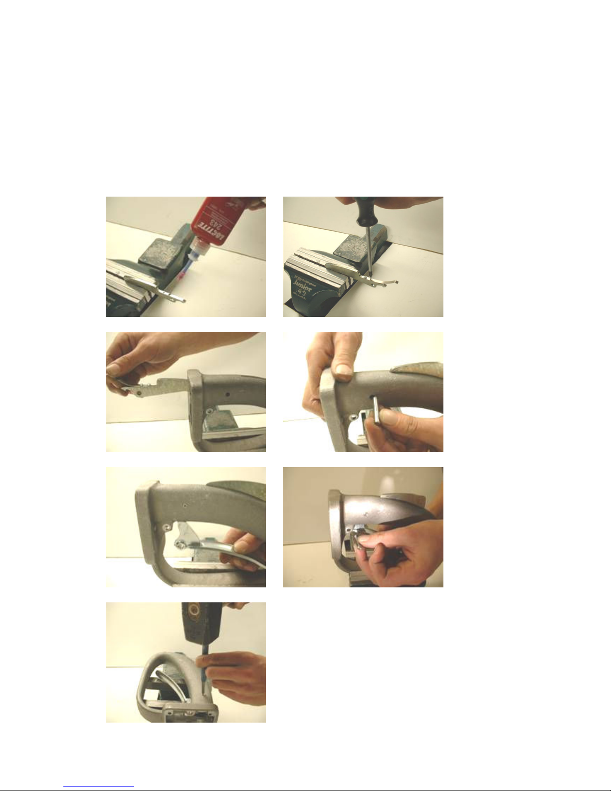
22
Mounting
Add Loctite 243 to the two threads in the safety trigger, and mount the leaf spring
with the two screws. Insert the safety trigger in the handle and push the pin w/hole
through the handle and safety trigger. Insert the trigger lever in the handle and
mount the pin through handle and trigger lever. Mount the retaining rings on both
sides of the pin. Place the entire handle on a firm surface so that the pin does not
slip out when hammering on it. With a hammer and a punch expand the hole in the
pin so that the pin is firmly secured. Do this from both sides.
Page 24
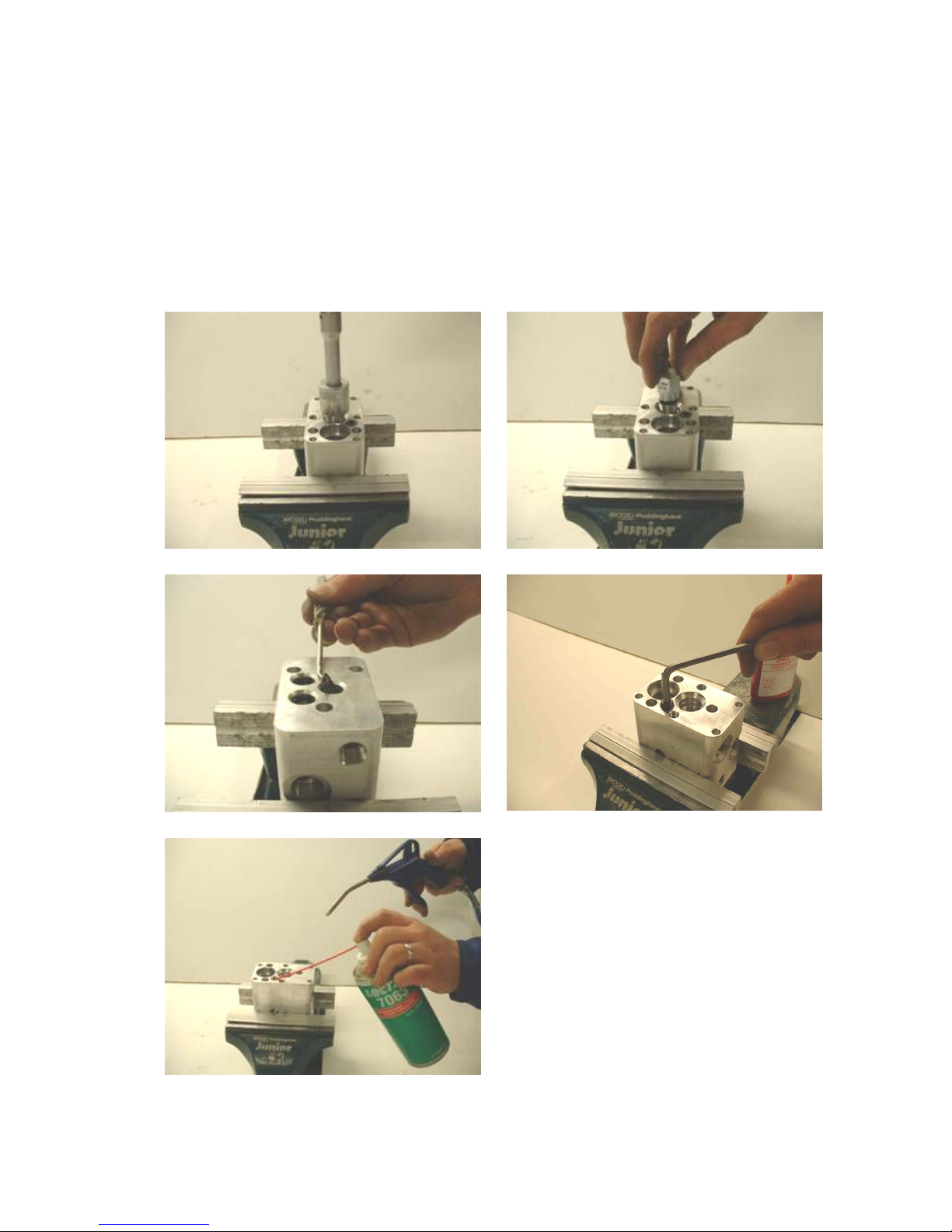
23
10. Repair of Valve Block
Dismounting
Dismount the check valve, degrease with Loctite 7063 and clean it with compressed
air. Dismount O-rings (O-rings cannot be used again due to risk of leakages). If
necessary dismount the pipe plugs (only dismount if one of them is leaking) and
clean with Loctite 7063. Finally clean the entire valve block with Loctite 7063.
Page 25
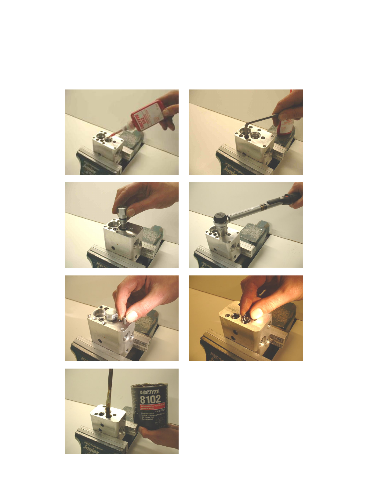
24
Mounting of Valve Block
Add Loctite 542 to the threads, and mount the pipe plugs. Mount the check valve in
the valve block, and tighten it with a torque of 40 Nm. Place the four cylinder pins in
the corner holes. Mount O-rings in the three holes and grease.
Page 26
25
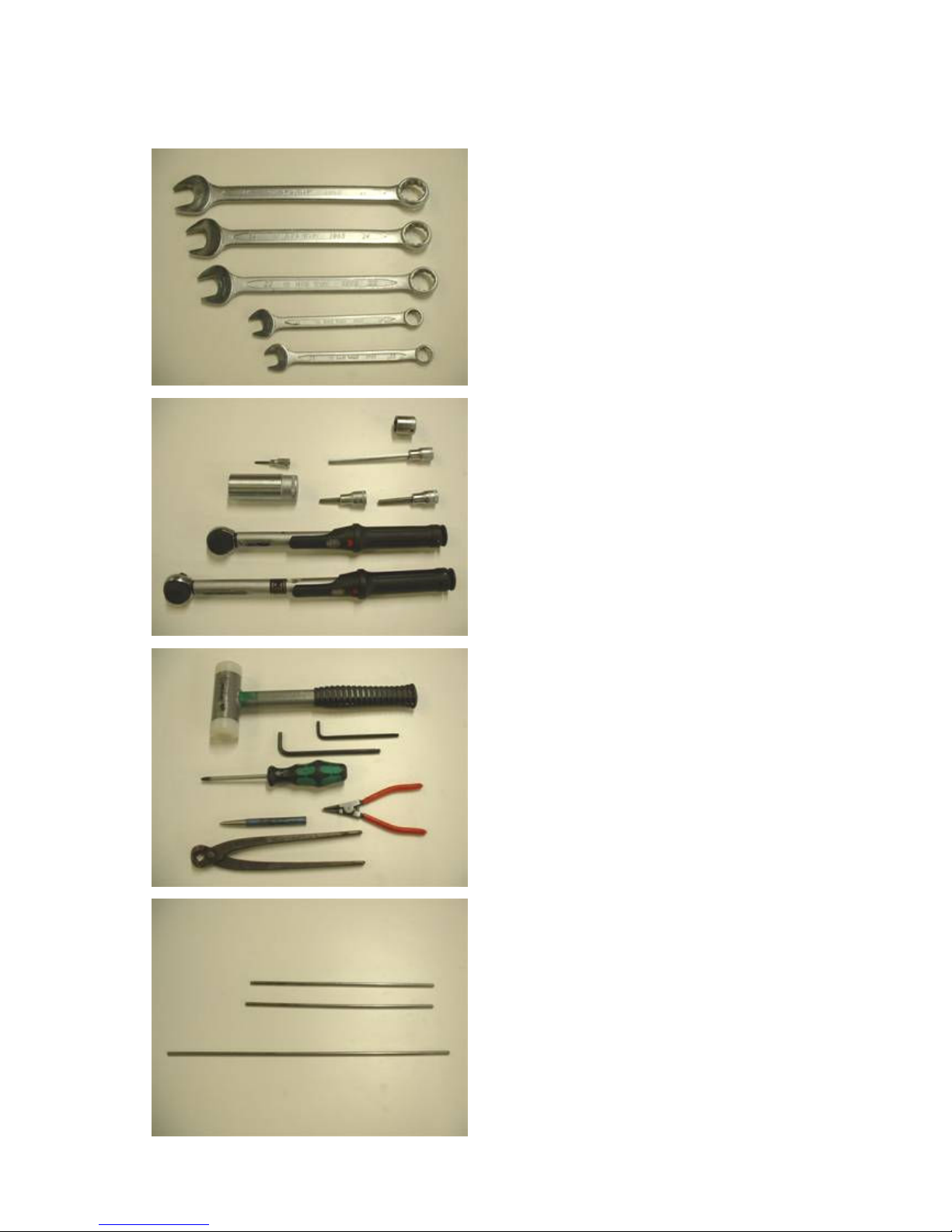
11. Tool List
c
g
h
i
j
k
l
a. Combination spanners,
Sizes 13, 14, 22, 24, 27
b. Torque wrench 2-25 Nm
c. Torque wrench 5-50 Nm
d. Hex head socket drivers for torque wrench
Sizes 3/16”, 2.5 mm, 5 mm, 6 mm, long
e. 24 mm socket, long
f. 19 mm socket
g. Hex head wrenches, sizes 6 mm, 3/16”
h. Hammer
i. Centre punch
j. Screw driver PZ 2
k. End cutter
l. Small external circlip plier
m. HYCON special tool No. 9992079
consisting of 6 mm round steel bars
2 x 31.5 cm, 1 x 45.5 cm
For mounting of hydraulic pipes and
water pipe in the frame
 Loading...