

Page 1
Odyssey Easy Installation Guide
Page 2

Safety
Hycomp ensures that safety is designed into every
compressor. An Odyssey booster is a precision, high
speed, mechanical piece of equipment. It requires
caution in operation to minimize hazard to self and
property.
INSTALLATION CHECKLIST - REVIEW BEFORE CONTINUING
q Reciprocating boosters must be mounted
on a reinforced concrete foundation (6 bag /
4000psi mix) and mounted with epoxy grout, per
“Foundation” section of this manual.
q Compressors and packages mounted to onshore
transportable platforms or any elevated structure
must be securely fastened to adequately
constructed subframes.
q Allow for 18” of clearance for air circulation and
service access around the booster. 36” in front of
the Control Panel. See “Location” section.
q Outdoor compressor installations must be
protected from the eects of the environment;
e.g. cold, heat, rain, sun, dust, etc. Machinery
exposed to the elements requires increased
maintenance and experiences decreased service
life. A block heater with thermostat is required for
cold climates.
q A power disconnect for the machine must
be installed as per NEC & local power utility
code. Follow Lockout/Tagout procedures, per
OSHA Regulation 1910.147, before any work is
performed. Do NOT work on equipment while it
is running.
q Lockout/tagout the compressor control panel and
tighten all electrical connections within the control
panel before startup. Connections can come
loose during shipping leading to intermittent
faults.
q Use threaded or anged exible braided metal
hose connections of proper pressure rating to
connect the booster system suction and discharge
ports. Do not use rubber hose.
q Nitrogen Boosters must have an suction receiver
sized per “Receivers” section of this manual.
Ensure that suction and discharge receiver tanks
are secured and bolted down.
q Place properly sized pressure safety valves
protecting the suction and discharge piping
systems, between the compressor and any
isolation ball valve, per ASME Code.
All Odyssey boosters have various caution, warning,
and danger labels which must be heeded and should
not be removed. Before operating or performing any
maintenance, read the Odyssey Operation Manual.
q Install supplied check valve into dedicated port of
discharge receiver tank.
q Protect personnel from high temperature piping/
tubing by insulating, warning, and or restricting
access to the machine boundary.
q Pressure sensing lines to pressure transmitters
must be 3/8” tubing or larger, and drawn from
the corresponding receiver, not from the suction/
discharge piping.
q Route clear tubing, located on motor side of
booster, to an oil catchment location. Small
amounts of oil will accumulate over time.
q Use double nut, Nyloc nut, or Loctite on foundation
bolting. Check all bolting after the rst few hours
and days of operation for tightness.
q Re-torque all head and ange bolts after the rst
40 hours of operation, per the Odyssey Operation
Manual.
q Re-tighten pressure connections, including tube
ttings, pipe connections, and ange connections,
after initial operation.
q Odyssey Boosters must have a properly sized
lter installed at the suction receiver inlet to
protect the booster from damage caused by
system contamination. Filter should be 1 micron
or better and sized for minimal pressure drop.
q Boosters are shipped with ISO/SAE 30 wt
synthetic oil. Refer to Odyssey Operation
Manual to ensure this is appropriate for your
environmental conditions.
q Check your system for leaks, x as required.
Remove all pressure from system, isolate
and drain, before attempting xes, per OSHA
Regulation 1910.147
q Ensure all components and piping installed with
Odyssey booster are compatible with Nitrogen.
q Complete the Hycomp Warranty Registration
Card and Warranty Checklist.
Page 3
CONTENTS
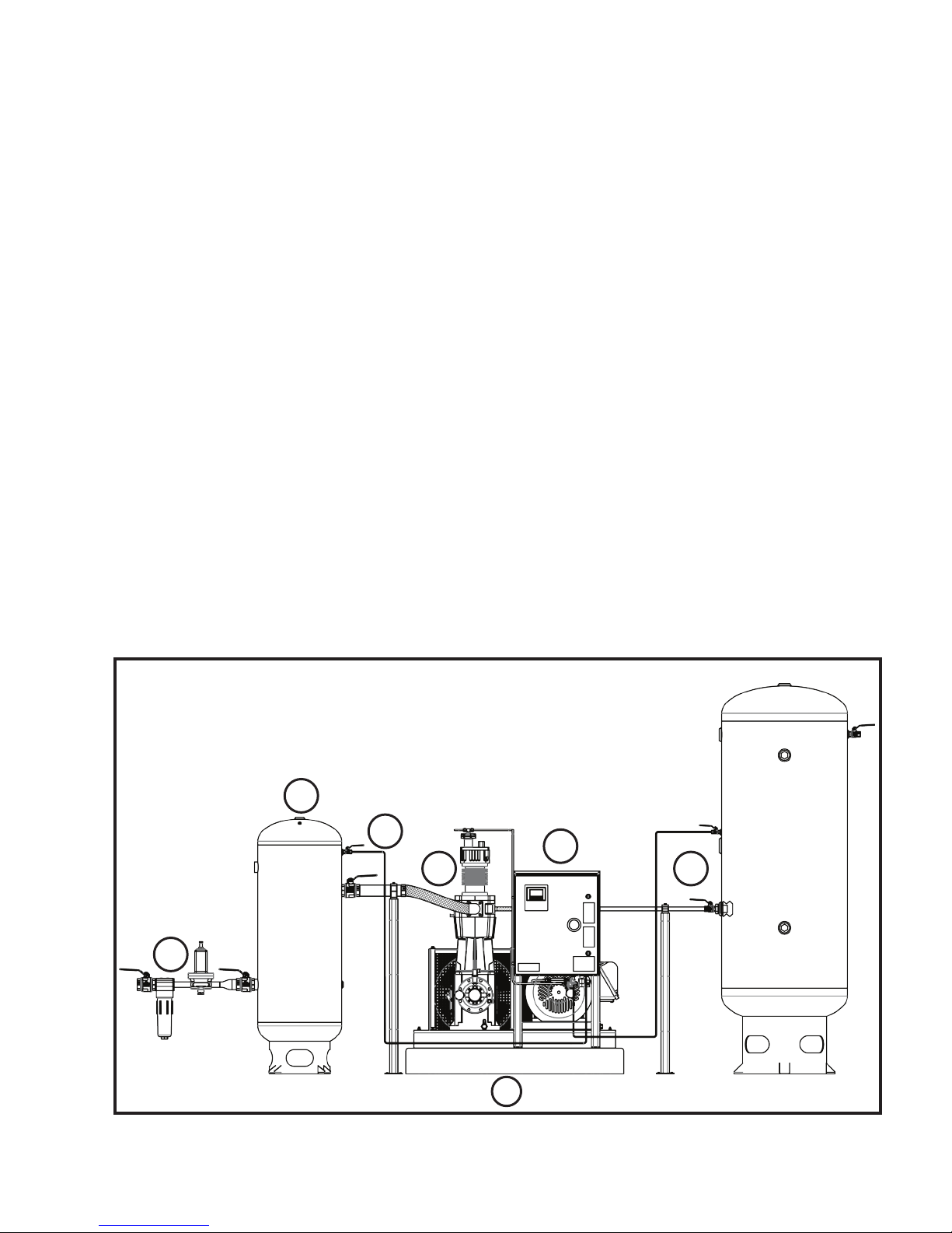
i. Safety.............................................................................................................................................................................2
ii. Installation Checklist .....................................................................................................................................................2
1. Installation to Floor ........................................................................................................................................................4
2. Suction Filtration ............................................................................................................................................................4
3. Suction Receiver ...........................................................................................................................................................4
4. Suction/Discharge Pressure Sensing Lines ..................................................................................................................4
5. Flex Hose ......................................................................................................................................................................5
6. Booster Installation ........................................................................................................................................................5
Power Supply .............................................................................................................................................................5
Plumbing ....................................................................................................................................................................5
Piping .........................................................................................................................................................................5
7. Discharge Receiver and Discharge Check Valve ..........................................................................................................6
Service Distance............................................................................................................................................................6
General Information .......................................................................................................................................................7
Notice to Hycomp Customers ........................................................................................................................................7
Booster Installation ........................................................................................................................................................7
Receipt of Booster ......................................................................................................................................................7
Location ......................................................................................................................................................................7
Foundation .................................................................................................................................................................7
Suction Piping and Filtration.......................................................................................................................................8
Discharge Piping ........................................................................................................................................................8
Receivers ...................................................................................................................................................................9
Safety .........................................................................................................................................................................9
3
2
ODYSSEY-M01-001 Rev. 0
4
6
5
1
PRINTED COPIES FOR REFERENCE ONLY
7
3
Page 4
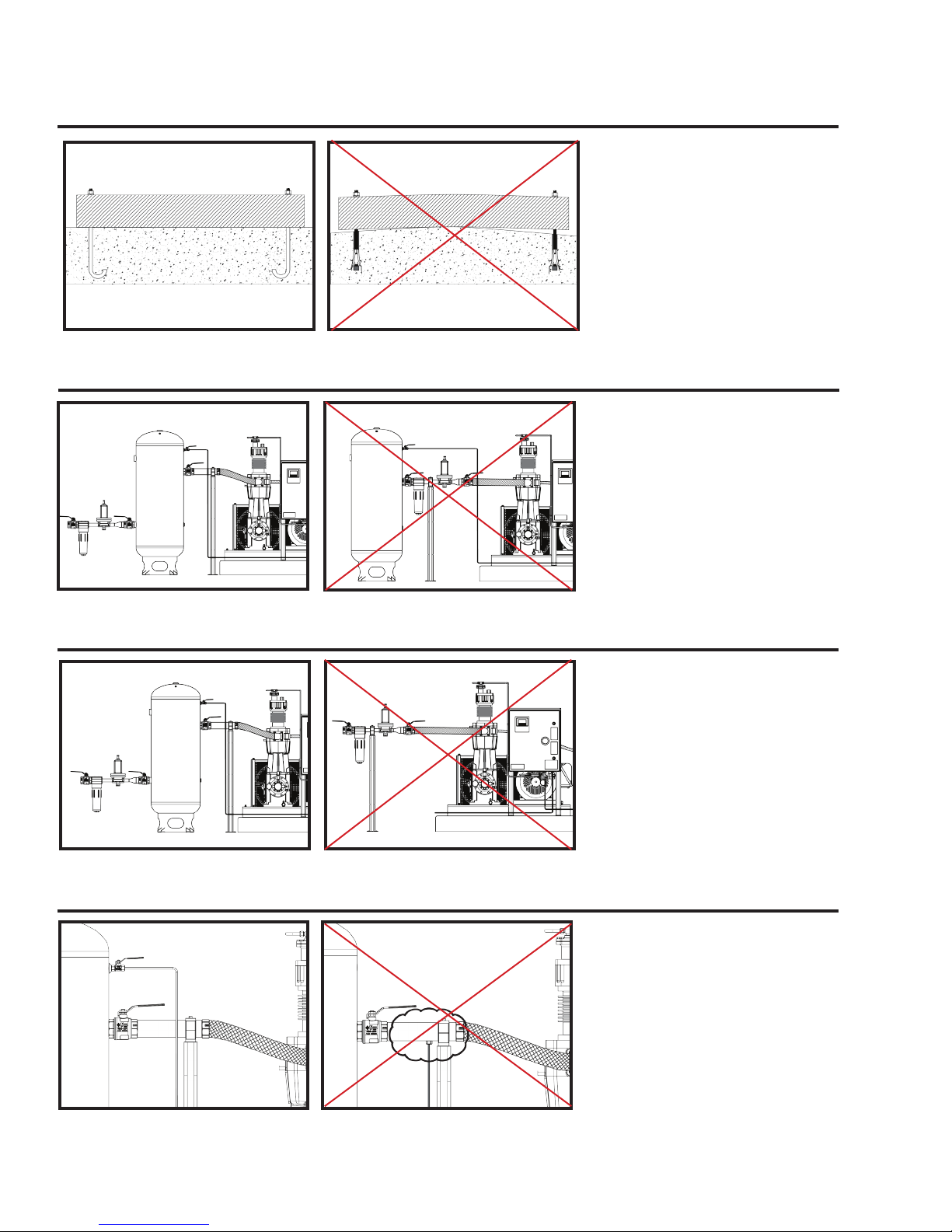
1. Installation to Floor
2. Suction Filtration
3. Suction Receiver
Required: Cement pad on solid
bedrock, packed earth, or gravel
required. Booster must be level,
with 100% contact to mounting
surface. Wedge anchors may not
be used.
Recommended: Use of “J” bolts or
MaxiBolts.
See “Foundation” section for pad
weight and dimensions
Required: The use of a minimum
1 micron lter is required prior to
the suction receiver. Filter must be
rated for twice the full ow of the
booster. If specied, a pressure
regulator is also required.
Recommended: Manual ball valve
should be placed on either side
of lter and pressure regulator to
enable service isolation.
See “Suction Piping and Filtration”
section
Required: A clean suction receiver
tank must be placed immediately
prior to the booster.
Recommended: Suction tank
size should be 1 gallon per scfm.
Manual ball valves should be
placed on either side of suction
receiver to enable service isolation.
Tank should be placed within 10’ of
the booster.
See “Receivers” section
4. Suction / Discharge Pressure Sensing Lines
Required: Pressure sensing lines
must be run directly to respective
tanks. Piping must be no smaller
than 3/8”. Pressure sensing
lines must be rated for working
pressure of system
Recommended: Manual ball valve
should be placed on both suction
and discharge pressure sensing
lines to enable service isolation.
4
PRINTED COPIES FOR REFERENCE ONLY
ODYSSEY-M01-001 Rev. 0
Page 5
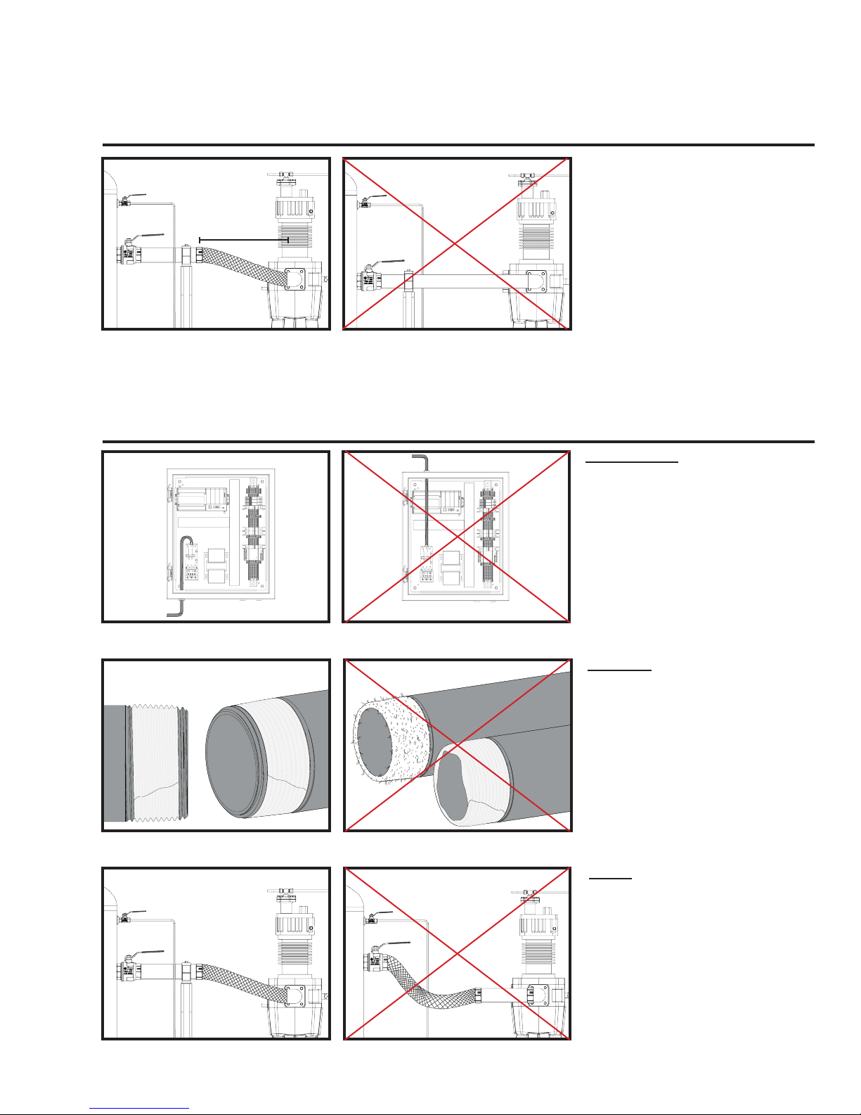
5. Flex Hose
18”
6. Booster Installation Overview
Required: A ex hose with a length
of at least 18” must be used on both
suction and discharge sides of the
booster. Proper sizing must be used
to accommodate for temperature,
pressure, and pulsation.
Recommended: Stainless steel
ex hoses should be used.
Power Supply
Required: A connection of proper
voltage is required. Voltage is listed
on the inside of the door to the
Odyssey control panel. Connection
must not penetrate top of enclosure.
A red tag located in the control panel
shows where 3 phase power is
connected.
See Parts Manual for “Motor
Diagram”
ODYSSEY-M01-001 Rev. 0
PRINTED COPIES FOR REFERENCE ONLY
Plumbing
Required: No pipe dope may be
used in installation. Thread tape
must be placed no less than 1.5
threads away from connection.
Recommended: Purge line of
debris prior to connecting the
booster.
See “Suction Piping and Filtration”
section
Piping
Required: No pipe load is to be
supported by the booster. Pipe
systems must have rigid supports
per local codes.
5
Page 6
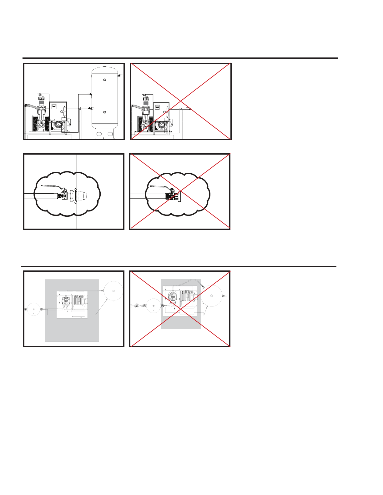
7. Discharge Receiver and Check Valve
Required: A clean discharge
receiver tank must be placed
immediately after the booster.
Recommended: Tank size should
be 2 gallon per scfm. Manual ball
valves should be placed on either
side of discharge receiver to enable
service isolation. Tank should be
placed within 20’ of the booster.
Required: Boosters must have
dedicated disc type discharge check
valve rated for working pressure.
Units with multiple Boosters must
have multiple check valves.
NOTE: In-tank discharge check
valve(s) are shipped loose for local
installation.
Service Distance
18”
18”
36”
18”
3”
10”
16”
5”
Required: Control panel must have
36” clearance or local regulation
requirement, whichever is furthest.
Recommended: Booster should
be placed with at least 18” distance
between other components for
serviceability and air circulation.
6
PRINTED COPIES FOR REFERENCE ONLY
ODYSSEY-M01-001 Rev. 0
Page 7

GENERAL INFORMATION
NOTICE: Odyssey boosters must only be installed in systems which have been designed by qualied personnel.
The system MUST conform to all applicable federal, state, local and national standards.
This manual is intended to assist qualied technical personnel in the installation of Hycomp Nitrogen Boosters.
NOTICE TO HYCOMP CUSTOMERS
Hycomp recommends you order service and replacement parts according to the model number and serial number
found on the nameplate of your booster. Do not order parts from the general descriptions in this manual. Ordering
directly from Hycomp or a registered vendor will minimize the possibility of receiving incorrect parts for your booster.
BOOSTER INSTALLATION
outdoors, provide a rain cover or a completely enclosed
RECEIPT OF BOOSTER
Immediately upon receipt of the booster, inspect the
unit and associated components for damage that may
have occurred during shipment. Shipping damage
is not covered by Hycomp. Notify the shipping
company if there have been any damages.
Upon receipt of the booster, read the booster nameplate
to confirm the model ordered. Read the motor
nameplate to ensure that the electrical requirements do
not exceed existing conditions. Hycomp requires that
all personnel in charge of installation, maintenance,
or service of a Odyssey booster read this manual and
Operation Manual in their entirety.
LOCATION
Locate the booster in a dry, well ventilated and well lit
area that accommodates inspection and maintenance
access. Provide an unobstructed machine boundary of
at least 18” with adequate air ow and service space
around the booster. The area in front of the control
panel requires at least 36”. Check local electrical codes
to ensure proper distance. Rotating machinery should
always display appropriate restrictive warnings and
cautions to minimize risk of injury to personnel.
Rotating machinery can be a source of noise, which
may require abatement or personnel exposure limits.
Understand your service environment and prepare
accordingly. Noise from a typical Odyssey booster
may exceed 80 dBA @ 3ft.
Installation in locations exposed to ambient subfreezing
temperatures is not recommended. Exposure to direct
sunlight, rain, wind, dust, snow, moisture, and other
adverse environmental elements is not recommended
and will reduce service life and increase maintenance
requirements. If it is necessary to install the unit
ODYSSEY-M01-001 Rev. 0
PRINTED COPIES FOR REFERENCE ONLY
shed to prevent corrosion.
If it is necessary to install the unit in a location that
will experience operating temperatures below 32°F, a
Hycomp crankcase heater must be installed. If the
booster is liquid cooled, suitable freeze protection must
be provided for both the coolant and the machine.
FOUNDATION
Installations require the booster be secured to a
concrete foundation pad. The foundation should
rest on solid bedrock, compacted earth, or gravel,
but not a combination of any. The pad should be
composed of 4,000 psi cured concrete reinforced with
ASTM A615 #4 billet steel re-bar cross laced on 16”
centers located 3” above the base. Refer to Table 1
for amount of concrete required. SAE Gr. 5 “J” bolting
of appropriate length and size should be used in the
pad to provide baseplate mounting. Use of a template
to support and position the bolting +/– 1/16” while
setting concrete is recommended. Securing bolting to
existing foundations with drilled holes and adhesives
is not to be used, unless expert advice is available.
Booster
Model
DS015 27 52 8 975
DS026 27 52 8 975
DS033 27 52 14.5 1767
DS044 27 52 14.5 1767
DS060 31 56 16 2411
DS081 42 62 20 4521
DS087 31 56 16 2411
DS192 55 84 16 6417
DS133 55 84 16 6417
DS303 55 84 16 6417
Table 1: Foundation Requirements
Width
(in.)
Length
(in.)
Depth
(in.)
Weight
(lbs.)
7
Page 8

2” Min.
All Sides
8” Min
Hex Nut
Washer
Booster Baseplate
Concrete Foundation with
Reinforcements Should
Be Used on All Models
“J” Bolts, Located Per
Booster Installation
Diagram
Figure 2: Foundation Requirements
Expert advice is also recommended for installation of
other forms of mechanical anchors. See Figure 2 for
additional details.
with minimal pressure drop. Suction lters must be
installed upstream of the suction receiver to prevent
pulsation damage. The suction receiver and piping
must be cleaned of any foreign residue before booster
startup. Unless otherwise indicated, nitrogen boosters
do NOT come with an suction gas lter. Damage to the
machine will occur if contamination is drawn into the
booster and will void the warranty! Do NOT use pipe
dope or excessive thread tape as these may damage
the booster.
Boosters are not designed to pump any liquids. Liquids
are non-compressible and even the slightest amount
of liquid can cause high-impact stresses resulting in
serious damage to the booster. The use of a liquid
trap in the suction line is required where the presence
of entrained liquids in the suction gas is a possibility.
Epoxy based grouting is required to rmly seat and
attach the booster skid to the concrete foundation.
ITW Philadelphia Resins brand “Chockfast Red”
grout is recommended. Sealing of grouts and
concrete is recommended to prevent contamination
by oil and moisture. Newly poured concrete must be
fully hydrated prior to grouting. The concrete slab
should be chipped to remove all latent and 50% of
the aggregate exposed to provide a rough bonding
surface for the epoxy. Dowels should be installed on
new exposed concrete to prevent edge lifting. The
concrete foundation should be dry and free of oil before
pouring grout. Sleeve all foundation bolts to prevent
adhesion and allow bolt stretch. Steel baseplates
should be sanded and cleaned to provide adequate
adhesion surface.
Steel fabricated foundations are generally not
recommended, but if necessary must be adequately
engineered to support the weight and vibration of the
booster.
SUCTION PIPING & FILTRATION
Booster life can be substantially increased by providing
clean, dry, cool gas to the booster suction. See Parts
Manual for general connection locations.
The suction piping must be rated for the working
pressure of the suction gas and protected with
a properly sized safety valve set at 10% (30 PSI
minimum) above the maximum operating pressure but
below the maximum allowable working pressure of the
pipe. All piping must have adequate piping support.
A suction lter must be placed in-line with the booster
inlet, to ensure clean nitrogen to the booster. The
lter should be a 1.0 micron or better, coalescing type,
suciently sized for twice the full ow of the booster
Flexible expansion joints must be placed within 36”
of the booster to help compensate for expansion/
contraction of the pipes, as well as isolate the vibration
of the booster from the rigid piping. All piping must be
adequately supported to ensure no piping loads are
placed upon the booster. Failure to do so may cause
a dangerous break in rigid pipe caused by vibration
in the piping.
DISCHARGE PIPING
Recommended practice is to have a booster aftercooler,
discharge safety valve, discharge check valve, and a
receiver. To prevent undesirable pressure drops in
piping, pipe size should be increased one size for each
100 feet of run.
It is extremely important that a properly sized safety
valve, set at 10% (30 PSI minimum) above the
maximum operating pressure but below the maximum
allowable working pressure of the system components,
be placed at the discharge receiver and upstream of the
aftercooler. Never place a line valve in the discharge
piping between the booster discharge and the safety
valve.
A discharge check valve must be installed in the
discharge receiver to prevent high pressure nitrogen
from leaking back through the booster to the suction
side of the system, causing dangerously high pressures
in the suction side receivers, piping, etc. A separate
check valve is required for each unit if the system has
more than one booster.
On initial start-up of the booster, bubble test all piping
connections for leaks with a soap-water solution. All
piping must be leak free.
All piping must be compatible with nitrogen and must
be rated above the pressure safety valve setpoint.
8
PRINTED COPIES FOR REFERENCE ONLY
ODYSSEY-M01-001 Rev. 0
Page 9

RECEIVERS
Reciprocating boosters create pressure pulsation
of both the suction and discharge gas streams. To
minimize the eects of pulsation phenomena, Hycomp
nitrogen boosters operate best with both an upstream
pulsation tank (sometimes called a buer or suction
receiver tank) and a discharge receiver tank.
Discharge receiver tanks must be separated from
the booster with a check valve.
Receivers should be sized as follows:
MINIMUM Suction RECEIVER SIZE:
Tank size (gal) = Booster SCFM
MINIMUM DISCHARGE RECEIVER SIZE:
Tank size (gal) = 2 X Booster SCFM
For example, a 97 scfm booster would require a
minimum 100 gallon suction receiver, and a minimum
200 gallon discharge receiver. Whether for suction or
discharge, a larger receiver is always better
SAFETY
Any changes to the booster operating parameters
should only be made with the approval of Hycomp.
Contact the factory should a change be necessary.
ALL INDUSTRIAL GASES WILL PROVE FATAL TO
PERSONNEL EXPOSED. Only air is capable of
supporting life. Nitrogen may cause short or long term
damage, or death, to personnel that are exposed.
Because there is NO SAFE GAS OTHER THAN
AIR, it is imperative that all exposure to nitrogen be
closely monitored and regulated. Federal mandate
requires specic procedures must be established for
any company that deals with industrial gases. This
includes, but may not be limited to, gas containment
policy, protection required for personnel working
with the gas, availability of SDS’s, specic training,
emergency spill and/or contact procedures, etc.
Always check if there are EPA or OSHA standards
that may apply.
Ensure all materials used in the booster and associated
plumbing, including coolers, separators, filters,
receivers, regulators, piping, etc. are compatible with
nitrogen. If unsure, contact the manufacturer of the
equipment.
BOOSTER NAMEPLATES
Each Hycomp model has a nameplate attached to the
crosshead guide cylinder, usually on the oil-pump end.
The information on this nameplate must be available
when ordering parts for the booster or requesting
assistance with troubleshooting, maintenance,
installation or operation.
Before contacting Hycomp, note who you purchased
the booster from, who installed it, installation date,
the purchase date, and model number. This will help
Hycomp identify your booster and any special parts
and materials that may have been used. Fill in the
information from the new booster into the spaces
provided in the sample nameplate below.
Contact Hycomp with installation questions which are not addressed in this installation manual.
Installed By ________________________________
Installation Date_____________________________
Purchased Date_____________________________
Purchased From ____________________________
Date of Startup______________________________
Model #___________________________________
Serial #____________________________________
ODYSSEY-M01-001 Rev. 0
PRINTED COPIES FOR REFERENCE ONLY
9
Page 10

 Loading...