

Page 1
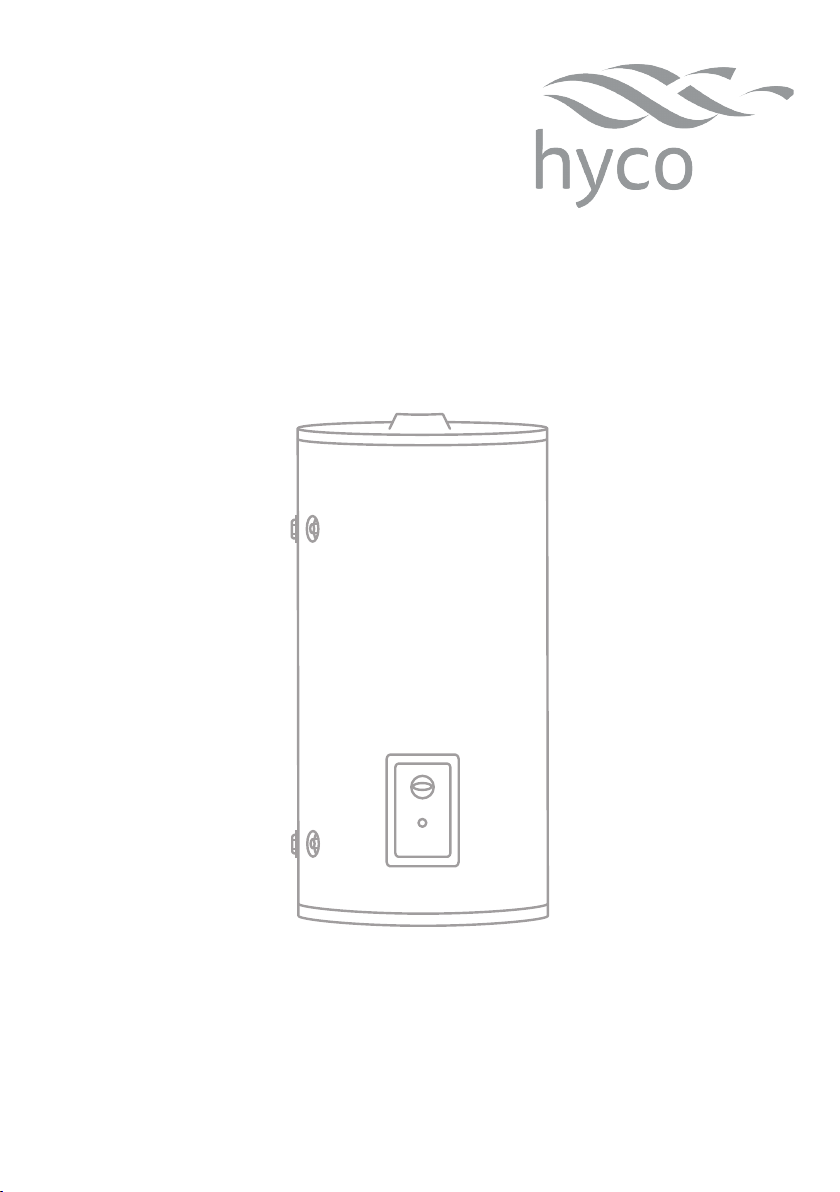
Product Instruction Manual
Superow
SR90, SR140
Unvented Multipoint Water Heater
v21.8.1
Page 2
Overview
Thank you for purchasing a Superow series unvented electric water heater. The Superow
is suitable for hand washing and dishwashing where a number of hot outlets are required
such as kitchens, schools, restaurants, washrooms and oces. The Superow is the ideal
solution for industrial, commercial and light domestic hot water requirements.
Please read and understand these instructions before commencing installation and leave
them with the user when installation is complete.
Please fully read these instructions before commencing installation and follow to ensure
that installation and operation are simple and safe.
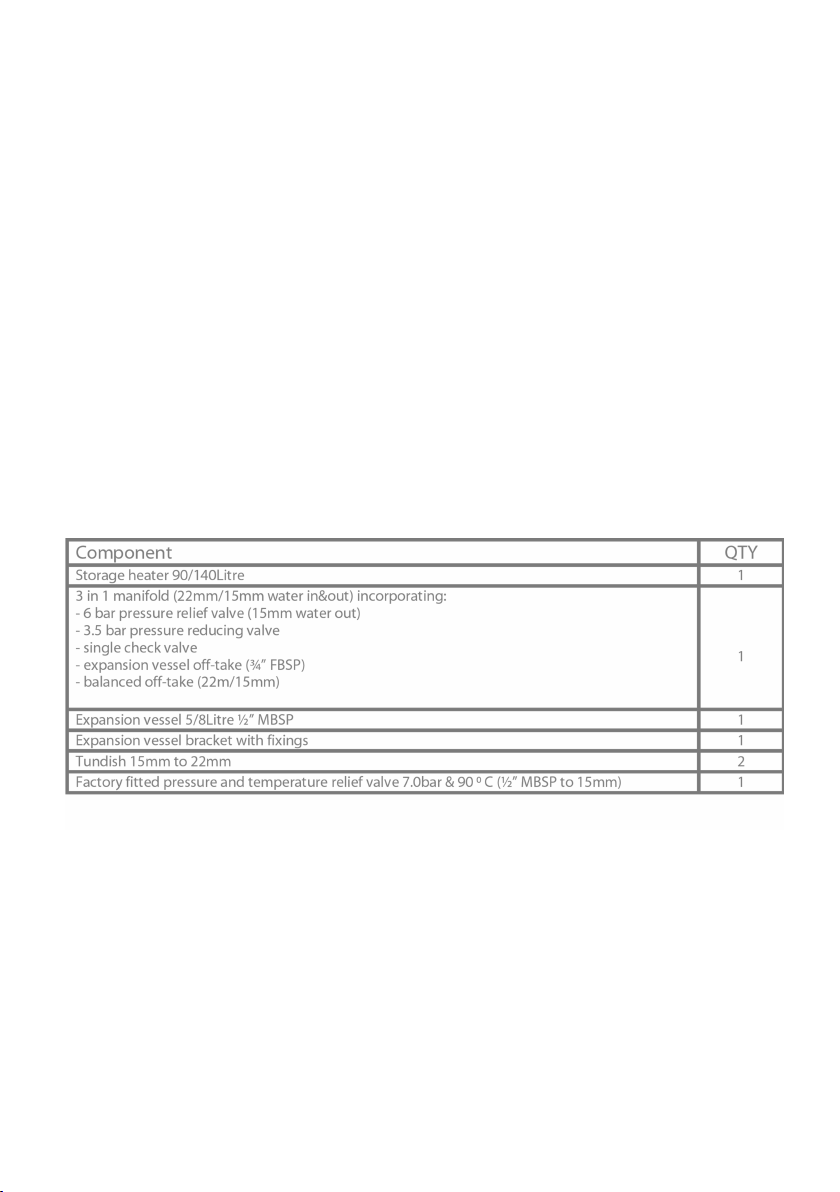
Component Checklist
2
Page 3

1. Important Safety Points
Installation must be undertaken by a competent installer of unvented water
heating systems in accordance with building regulations G3.
Building regulations G3 require a temperature and pressure relief valve to be
factory tted. This must not be removed or blocked in any way.
Installation must comply with the latest edition of the IET wiring regulations.
2. Installation
The unit must be installed vertically with the temperature and pressure relief
valve at the top.
The heater is not suitable for installation outside.
Do not install the heater where there is any risk of freezing.
The heater is large and heavy, do not attempt to lift alone.
• Plan your installation carefully in advance, allowing suitable space for installation and
future access to all ttings as shown in diagram 1 or 1a, depending on unit capacity.
3
Page 4
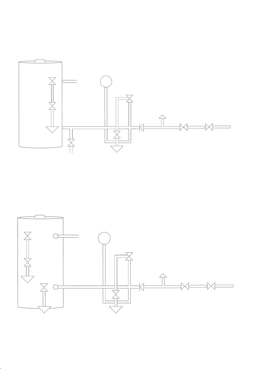
Installation Diagram 90 L Model
SUPERFLOW
Expansion
Pressure &
Temperature
Relief Valve
Tundish
Drain
(Waste)
Diagram 1
Hot
Out
Tundish
Drain
Cock
Vessel
Drain
(Waste)
Installation Diagram 140 L Model
SUPERFLOW
Pressure
Relief Valve
Check
Valve
(Expansion)
Balanced
O Take
Pressure
Reducing
Valve
Cold
Mains In
Service
Valve
Pressure &
Tempreature
Relief
Valve
Tundish
Drain
Cock
Diagram 1a
4
Drain
(Waste)
Drain
(Waste)
Hot
Out
Tundish
Expansion
Vessel
Drain
(Waste)
Pressure
Relief Valve
Check
Valve
(Expansion)
Balanced
O Take
Pressure
Reducing
Valve
Cold
Mains In
Service
Valve
Page 5

Plumbing Connection
Observe the ow direction arrows on ttings.
It is importan
Do not remove the factory fitted pressure and temperature relief valve.
Do not insert any other valves between the main manifold and heater inlet as it
may prevent the safe expansion and discharge of water during heating cycles.
• Make the necessary connections, as per diagram 2 on page 6, to the inlet side of the
heater (as indicated by the blue collar).
• It is recommended a service valve (not supplied) is fitted upstream of the installation
in order to facilitate future maintenance.
• It is recommended that the “balanced off take” is used to supply any cold outlet that is
paired to a mixer style tap supplied by the hot feed of the unit.
• The orientation of the expansion vessel is important, it should be fixed firmly to the
supplied bracket in a vertical orientation with the water connection at the bottom
and located so that the length of the connecting pipework is kept to a minimum.
• A drain cock (not supplied) should be fitted to a branch of the incoming supply pipe
at a point that is lower than both the unit and the expansion vessel (see diagram 1 or
1a) in order to allow full drain down for any future maintenance work.
• Make the connection to any hot tap/thermostatic mixing valve from the outlet side of
the heater (as indicated by the red collar).
t that the ordering of the ttings is correct as per the diagram 1 and 2.
5
Page 6
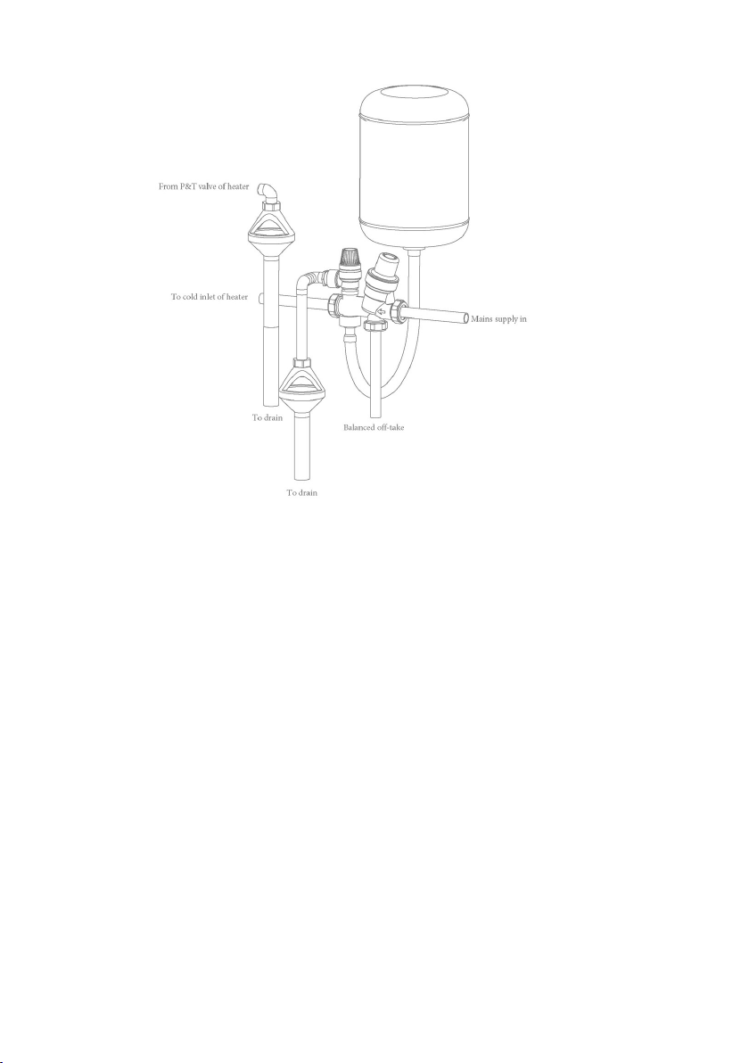
Diagram 2
Discharge Pipe Connection
This product falls within the scope of Building Regulation G3 which stipulates certain
conditions relating to the way any water discharge from relief valves is transported away.
These conditions are designed to ensure that any discharge will not present a hazard
to people or to property and that any discharge is clearly visible so that the underlying
cause is likely to be rectied promptly.
The essential requirement of G3 in relation to water discharge is that the discharge pipe
MUST terminate in a safe, visible position.
In achieving this aim the G3 regulations strongly recommended that:
• The tundish is located within 500mm of the pressure and temperature relief valve
and it is wherever possible oriented vertically. It must be visible to occupants and
positioned away from electrical devices.
• The discharge pipe has a vertical fall of at least 300mm immediately below the
tundish.
6
Page 7
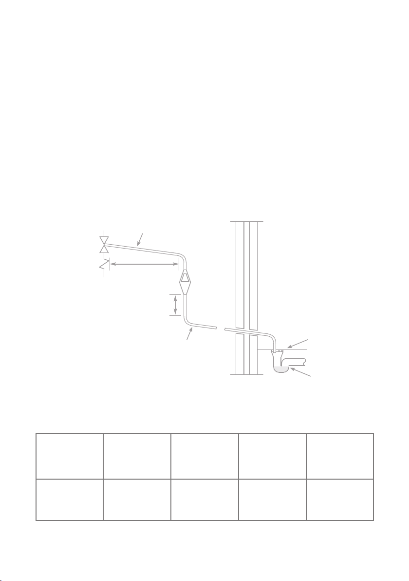
• The discharge pipe below the tundish is at least 22mm diameter (i.e. one size larger
than the pressure and temperature relief valve outlet).
• The discharge pipe should be as straight and as short as is possible and positioned
away from electrical components.
Diagram 3 illustrates an acceptable discharge pipe arrangement. The table below the
diagram species how the maximum acceptable pipe length from the tundish to the
nal outlet depends on the pipe diameter and the number of bends.
For example, in 22mm copper with no bends the pipe could be up to 9m long. With two
bends present the maximum length drops to 9.0m - (2 x 0.80m) = 7.4m.
Metal Discharge Pipe (D1) from
Temperature Relief to Tundish
Safety Device
600mm MAXIMUM
Tundish
300mm MINIMUM
Discharge Below
Fixed Grating
Metal Discharge Pipe (D2) from
Tundish with Continuous Fall
Fixed Grating
Diagram 3
Sizing of D2 copper discharge pipe for common temperature relief valve outlet size.
Valve outlet size Minimum size of
discharge pipe (D1)
G1/2 15 mm 22 mm
Minimum size of
discharge pipe (D2)
from tundish
28 mm
35 mm
Maximum resistance
allowed, expressed
as a length of
straight pipe (i.e. no
elbows or bends)
up to 9 m
up to 18 m
up to 27 m
Trapped Gully
Resistance created
by each elbow or
bend
0.8 m
1.0 m
1.4 m
7
Page 8
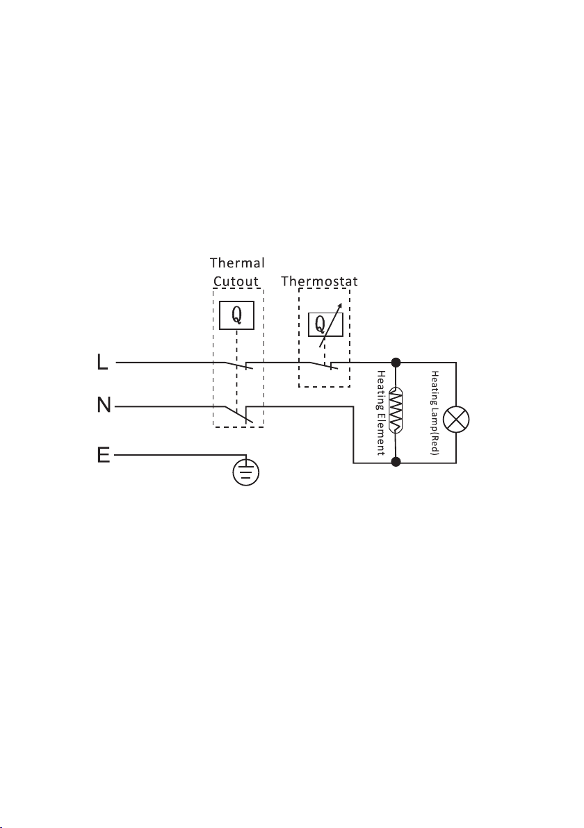
Electrical Connection
• The heater is supplied pre-wired with the appropriate cable.
• The electrical installation should conform to the latest edition of the IET wiring
regulations.
• Electrical supply should be capable of isolation via a user-accessible double
isolation switch rated for 13A supply.
Diagram 4
8
Page 9

3. Commissioning
• Visually conrm all plumbing and electrical connections look sound.
• Open any tap connected to the hot side of the unit and then turn on the incoming
water supply to the heater.
• Allow the unit to ll until water ows smoothly from the open tap for around 1 min
to ensure the tank is purged of air and any plumbing related debris.
• Close the tap and then inspect the system for any leaks.
• Check the pressure and temperature relief valve by twisting the cap to the open
position and observing the ow at the tundish. Ensure the discharge pipe can cope
with this ow continuously for several seconds.
• Release the cap and check that the valve reseals.
• Check the pressure (expansion) relief valve by twisting the cap to the open position
and observing the ow at the tundish. Ensure the discharge pipe can cope with
this ow continuously for several seconds. Release the cap and check that the valve
reseals.
• Turn on the electrical power and turn thermostat knob to the desired setting to
begin heating.
• Whilst the unit heats, the element lamp will illuminate. If it does not then check the
power supply.
• Once the heater reaches the desired setting and the element lamp goes out, visually
check all plumbing connections remained sound and no valves have discharged.
9
Page 10

4. Operation
The maximum temperature setting of the heater is 65°C, this can be excessively hot
for some users. In situations where very young children, the elderly or other
vulnerable people are the likely users, then a suitably rated thermostatic mixing
valve should be fitted to the hot water outlets as required.
Never interfere with any of the safety devices.
Beware that very hot water could discharge from the safety valves.
If there is risk of freezing the heater should be left on at least the minimum setting
to prevent potential damage to the product or property from frozen pipes. If the
heater is going to be left unused for a long period of time it should drained.
• Turn the thermostat clockwise to increase the temperature setting.
• Turn the thermostat anticlockwise to decrease the temperature
setting.
• The element lamp will illuminate whilst the unit is heating.
• The element lamp will go off once the temperature set point is
reached.
5. Maintenance
Always disconnect the heater from the power supply before commencing any
maintenance task.
Servicing of electrical components should only be undertaken by competent
individuals.
Draining the unit
• To drain the unit, first isolate the power supply and close the nearest service valve
on the upstream of the heater.
• Open the drain cock on the cold inlet and open a hot outlet to enable air to replace
the draining water.
10
Page 11

Resetting the thermal cut- out
If the earthing points are removed always ensure a rm reconnection before
re-commissioning of the heater.
• If the unit stops heating and the element lamp does not illuminate, an over
temperature event may have occurred. The unit is fitted with a manually resettable
thermal cut-out.
• Open any outlet and flush through any remaining hot water in the tanks until it runs
cool before closing it again.
• Ensure the unit is isolated from the power supply and then proceed to remove the
component cover, this is the housing that contains the thermostat and element
indicator.
• Once the cover is removed, locate the thermal cut-out, and press the button firmly
until a click is heard.
• Replace the cover and turn on the power.
• If the thermostat setting was at maximum when the unit cut-out, consider turning it
down (anticlockwise) to avoid any further cut-out events in the future.
Inspecting the anode
• The unit is fitted with a magnesium sacrificial anode; its purpose is to attract any
corrosion which in turn helps to protect the tank. Over time the anode will break
down and need replacing to ensure continued protection.
• It
is recommended the anode is inspected at least annually and replaced as required.
The anode can be inspected without the need for a full drain down of the unit.
• The power and water must be isolated and an outlet should be left open to allow the
unit to expel any excess pressure in the system.
• The anode is located under a cover on the top of the unit, remove the cover and
then in turn the anode retention ring via the 5 nuts.
• Once the retention ring is removed the anode boss should come free with a little
encouragement. Inspect the anode for signs of excessive corrosion/pitting and
replace if necessary.
• Reverse the steps to re-fit the anode and then refer to the commissioning section of
this manual.
11
Page 12

Safety valve inspection
• The pressure & temperature valve and the pressure (expansion) relief valves are
important safety features of the heater and should be tested periodically to ensure
correct functioning.
• To test the valves, twist the caps and check that water ows freely. The tundish will
allow for visual conrmation that water is owing during the test.
Pressure reducing valve maintenance
• Isolate the water supply to the pressure reducing valve and drain down the main
heater (see "Draining the unit").
• Unscrew the plastic cap of the pressure reducing valve and remove the complete
mechanism from the brass housing of the valve.
• Check there is no debris or grit build up in the wire mesh and remove by rinsing as
required.
• Replace the mechanism into the brass housing and then recommission the heater
(see section 3).
• Particular attention should be given to ensure the mechanism has been seated
correctly into the brass housing and a sound seal has been made.
Expansion vessel maintenance
• The expansion vessel is supplied with a pre-charge of 3.5 bar, this pressure may be
lost over time and should be checked periodically to keep the vessel functioning
well and help prolong the lifespan of the tank.
• To check the pressure of the vessel, a reading should be taken while the unit is
switched off and the content of the tank has been cooled.
• Turn off the power to the unit and run any
cool
• Check the pressure reading and increase/ decrease as required (a standard pump
with built in pressure gauge is required).
12
water off from any hot outlet until it runs
Page 13

Legionella risk advice
In order that Legionella risk is kept to a minimum the following advice is given;
• The heater should be run at its maximum temperature setting (65°C) and ushed
through at regular planned intervals.
• The whole system should be drained if long periods of non-use are expected.
• The expansion vessel should be drained occasionally to ensure the water in it is
recycled.
13
Page 14
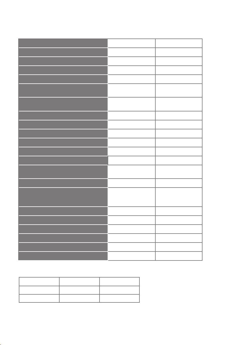
6. Specication
Model *1 kW available on request
Power
Supply voltage/ frequency 230V ~/50Hz 230V ~/50Hz
Current
Capacity 90 L 140 L
Maximum supply pressure (to pressure
reducing valve)
Minimum supply pressure (to pressure
reducing valve
Operating pressure 0.3 MPa (3 bar) 0.3 MPa (3 bar)
Maximum tank pressure 0.55 MPa (5.5 bar) 0.55 MPa (5.5 bar)
Expansion vessel pre-charge 0.35 MPa (3.5 bar) 0.35 MPa (3.5 bar)
Expansion vessel capacity 8 L 12 L
Pressure reducing valve pre-set 0.3 MPa (3 bar) 0.3 MPa (3 bar)
Pressure relief valve rating 0.6 MPa (6 bar) 0.6 MPa (6 bar)
Temperature and pressure safety valve
rating
Manual reset cut out rating 85 C 85 C
Immersion heater specication Part code: SR_EL3KW
Weight empty 29 kg 48 kg
Weight full 118 kg 187 kg
Heat up time from 10C to 60C 121 mins 180 mins
Recovery time of 70% capacity to 60C 86 mins 130 mins
Standing heat loss 1.67 kW/ 24h 1.91 kW/ 24h
Inlet/ outlet connections ½”MBSP ¾”MBSP
SR90 SR140
3.0 kW (*1.0 kW) 3.0 kW (*1.0 kW)
13A (*5A)
1.2 MPa (12 bar) 1.2 MPa (12 bar)
0.1 MPa (1 bar) 0.1 MPa (1 bar)
C/0.7MP
90
EN60335-2-21 x 1
a (7 bar)
13A (*5A)
90C/0.7MPa (7 bar)
Part code: SR_EL3KW
EN60335-2-21 x 1
7. Dimensions
Product Code Height (mm) Diameter (mm)
SR90
SR140
14
1040 410
1040 530
Page 15

9. Guarantee
This product is covered by a standard parts or replacement warranty for a period of 3
years from the date of purchase.
If there is a manufacturing defect within the warranty period we will send spare parts,
repair and return the unit or, at our discretion, supply a replacement product. Incorrect
installation, frost damage, the consequences of limescale deposits or failure to follow
correct operating and maintenance instructions are excluded. Consequential costs
such as labour charges or damage to ttings and surroundings are expressly excluded.
10.
Contact Us
If you experience a problem with this product you should rst contact our service
department on 01924 225 200 before taking any further action. Experience has shown
that issues can often be resolved without the need to return or uninstall the product.
15
Page 16

INFORMATION FOR CORRECT DISPOSAL OF THE PRODUCT IN ACCORDANCE
WITH THE EUROPEAN DIRECTIVE 2012/19/EU.
At the end of its working life this equipment must not be disposed of as household
waste. It must be taken to a local authority waste collection centre or to a dealer
providing this service. Disposing of electrical and electronic equipment separately
enables its components to be recovered and recycled to obtain signicant savings
in energy and resources. In order to underline the duty to dispose of this equipment
separately, the product is marked with a crossed out dustbin.
Hyco Manufacturing Ltd
Normandy Court
Express Way
Castleford, WF10 5NR
hyco.co.uk
T 01924 225 200
F 01924 225 210
E [email protected]
16
 Loading...