


Product Instruction Manual
Accona
AC500T, AC1000T, AC1500T, AC2000T
Panel heater
Version 3.2 Jan 2015
V18.4,1

Thank you for purchasing a Hyco Accona panel heater. Please ensure you
read and understand these instructions to ensure safe installation and
operation.
The Accona is ideal for a wide range of fixed installation heating applications in the home and
office environment. The Accona is ecodesign compliant; energy saving features include open
window detection and a 24/ 7 electronic timer.
Key Features
•
Slimline, modern, curved design
•
24/ 7 electronic timer
•
Reduced energy wastage with open window detection
•
Frost protection feature
•
Full or half power setting
•
IP24 splashproof
1. Important safety points
The electrical installation must be carried out by a qualified electrician in
accordance with the current edition of the I.E.E. Wiring Regulations.
Only connect the unit to a single-phase supply with a mains voltage as specified
on the rating plate.
If the heater is located in a bathroom, it must be installed so that switches and
other controls cannot be touched by a person in the bath or shower.
Only use the mounting bracket supplied and do not modify the bracket in
any way.
WARNING: To avoid overheating, do not cover the heater.
The supply cord cannot be replaced by the user. If the cord is damaged the
appliance should be returned to the manufacturer or an authorised service
agent for replacement.
The heater must not be located immediately below or above an electrical socket
outlet.
2

This appliance can be used by children aged from 8 years and above and persons
M
IN 300mm
MIN 150mm
MIN 150mm
MIN 150mm
with reduced physical, sensory or mental capabilities or lack of experience and
knowledge if they have been given supervision or instruction concerning use
of the appliance in a safe way and understand the hazards involved.
Children of less than 3 years should be kept away unless continuously
supervised.
Children aged from 3 years and less than 8 years shall only switch on/off the
appliance provided it has been placed or installed in its intended normal
operating position and they have been given supervision or instruction
concerning use of the appliance in a safe way and understand the hazards
involved. Children aged from 3 years and less than 8 years shall not plug
in, regulate and clean the appliance or perform user maintenance.
CAUTION: Some parts of this product can become very hot and cause burns.
Particular attention must be given where children and vulnerable people
are present.
2. Installation
Wall Mounting
•
Select a suitable location for the install and ensure the minimum spaces around the
heater are maintained to ensure good airflow and safe operation of the heater.
3

L
L1
H
H1
AC500T
MODEL
200 0/10 00830 400 300 254
150 0/75 0
595
400 250 254
100 0/50 0
460
400 155 254
500 /250
4
60
400 155 254
Specifica ti on
AC1000T
AC2000T
AC1500T
•
Remove the bracket from the reverse of the heater by pinching the two tabs at the
top to release it from the unit, and then unhooking the lower two tabs by tilting
the bracket away from the heater.
•
Ensuring a horizontal level, offer the bracket to the wall and mark the four holes
located at each corner of the bracket.
•
Drill the four holes in the mounting surface and insert the wall plugs supplied.
•
Offer the bracket up to the holes before inserting the four screws supplied. Ensure
the screws are fully tightened and that the bracket holds firm to the wall.
•
Offer the heater to the bracket and locate the lower bracket lugs into the
corresponding slots in the back of the heater by tilting the heater forward.
4

•
Recommended mounting height
(bottom edge of dryer above nished oor)
M
43”
L
41”
C
39”
C
33”
Once the lower lugs are located, tilt the heater back towards the bracket and align the
upper bracket lugs into the corresponding slots at the top of the heater.
•
Insert the screws into the upper lug holes and screw down until the heater is locked
into place.
Electrical installation
The electrical installation must be carried out by a qualified electrician in
accordance with the current edition of the I.E.E. Wiring Regulations.
•
Connection should be made to the fixed wiring of the property via a double pole
fused spur with a break capacity of no less than 13amps.
•
Electrical connections should be made as follows:
Green/Yellow earth wire to the terminal marked “ E” or
Brown/Red live wire to the terminal marked “L”
Blue/Black neutral wire to the terminal marked “N”
5

3. Operation
M/A
POWER
MON TUE WED THU FRI SAT SUN
LO HI WO M A
C
Set OK
Control panel overview
1. Standby on/off 7. Manual mode active 13. Time display
2. Full/half power select 8. Automatic mode active 14. Target temperature
3. Element on indicator 9. Timer active 15. SET select
4. Low power active 10. UP select 16. OK select
5. High power active 11. DOWN select
6. Open window active 12. Manual/Auto select
Once the heater has been switched on using the rocker switch on the right-hand side the
blue power LED indicator will be illuminated. You will then need to press the standby
on/off button under the LED indicator to activate the panel.
Setting the clock
•
Hold down the SET & OK buttons simultaneously until a beep sounds and the current
day setting flashes.
•
Use the UP/DOWN buttons to cycle to the correct day and press the SET button
to store.
•
The hour segment of the time display will flash with the current setting, use the
UP/DOWN button to cycle to the current hour and press the SET button to store.
•
The minute segment of the time display will flash with the current setting, use the
UP/DOWN button to cycle to the current minute and press the SET button to store.
6

The unit has a built-in battery that can retain the time for several days if the power is
switched off to the unit. If the unit is off for longer periods the day & time may need to
be reset upon next start up.
Setting the target temperature
•
To set the target temperature of the heater use the UP/DOWN buttons to cycle to the
desired value and press the OK button to confirm.
Switching between Full/Half power
•
Press the full/half power select button to toggle between the settings. The current
setting will be displayed by either the “LO” or “HI” icon on the display.
Switching between Manual/Auto operation
•
Press the manual/auto select button to toggle between the settings. The current
setting will be displayed by either the “M” or “A” icon on the display.
Setting the child lock
•
Press the UP & DOWN buttons simultaneously and hold until a beep sounds.
The target temperature display will be replaced by “[ ]” icon to indicate the
panel is locked.
•
Repeat the first step to unlock the heater.
Manual operation
The most basic setting of the heater allows the user to control when the heater is active
by simply switching between on/off via the standby button. However, it is strongly
recommended to consider setting a timed operation by using the ‘automatic operation
mode’ where anticipated usage is predictable, to avoid energy wastage.
•
Select the manual operation mode by pressing the manual/auto (M/A) select button.
To confirm the selection check that the “M” icon is displayed.
•
The heater will maintain the temperature displayed unless switched off or placed
into standby mode.
Manual operation (auto power off mode)
Whilst the heater is running in manual mode it is possible to control the length of time
the heater will operate for using a basic timer function. Using this you can select the
desired time for the heater to switch off. This feature helps to ensure the heater is not
turned on and forgotten about.
7
•
M/A
POWER
MON TUETTUTUE WED THU FRI SAT SUN
LO HI
TUEHTUE
HI WO M A
TUE
HI A
C
Set OK
Select the manual operation mode by pressing the manual/auto (M/A) select button.
To confirm the selection check that the “M” icon is displayed.
•
Press the SET select button to enter the power off time programming screen.
•
The hour setting will flash on the display. Use the UP/DOWN select buttons to
change the desired hour for the heater to turn off and press the SET select button.
•
The minute setting will now flash on the display and can be altered using the
UP/DOWN select buttons as per the previous step.
•
Once the desired hour & minute are displayed, press the OK select button to confirm
the power off time setting.
•
The heater will now display the “timer active” icon to confirm the feature is active.
•
The power off time setting will be cleared if the heater is switched off or placed into
standby mode.
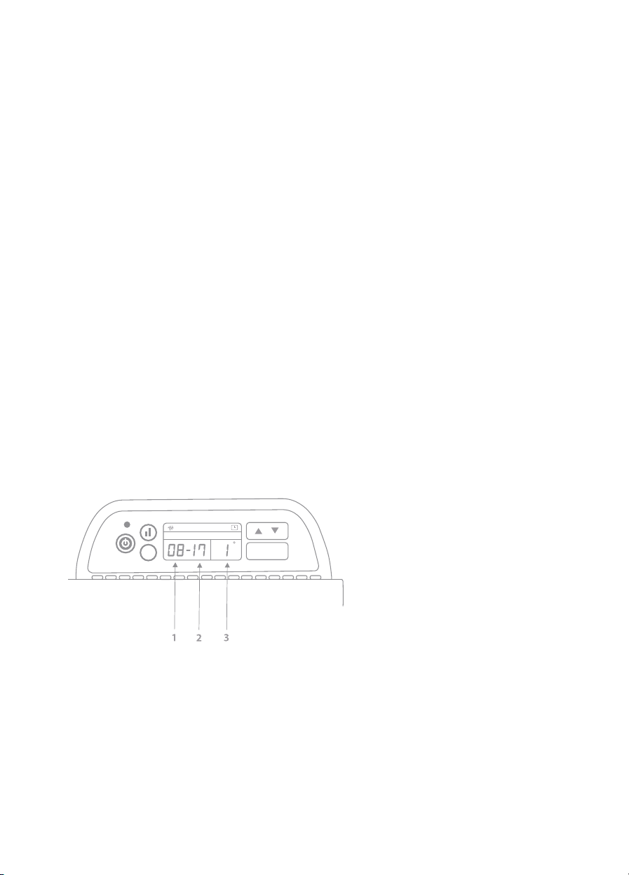
Automatic operation (24/7 timer)
Example below shows a timer programmed for TUESDAY to switch ON at 8.00am (08)
and OFF at 5.00pm (17). This is schedule number 1. See key for further information.
Key
1 Switch on hour
2 Switch off hour
3 Schedule number (1-4)
The automatic operation mode allows the heater to be operated by a user defined
schedule. This offers up to four separate periods of operation to be defined for each day.
This feature is strongly recommended where heat demand is predictable as it can help
reduce energy wastage. In addition, this allows spaces to be heated in anticipation of
the demand without the need for somebody to be present to turn it on; for example,
in an office environment where staff arrive to begin work at 8.30am, turning the heater
on at 8am to pre-warm the room.
8

•
Select the automatic operation mode by pressing the manual/auto (M/A) select
button. To confirm the selection check that the “A” icon is displayed.
•
Press the SET select button to enter the 24/7 timer programming screen.
•
The day setting will flash on the display. Use the UP/ DOWN select buttons to move
between the available days and press the SET select button to confirm when the
desired day to be programmed is flashing.
•
The time display will now show a flashing hour setting, this is the hour at which the
heater will automatically switch on (note it is only possible to set the timer to full
hours, minutes cannot be set). Use the UP/DOWN select buttons to choose the
desired hour to switch on and press the SET select button to confirm.
•
The second option to be set on the time display will now flash, this is the hour at
which heater will automatically switch off. Use the UP/DOWN select buttons to
choose the desired hour to switch off and press the SET select button to confirm.
•
The time display will now move to the next schedule you can create (shown by area
‘3’ on the annotated image) and the previous steps for setting the switch on and off
hours should be followed.
•
Up to 4 individual start stop times can be specified for each day but it is possible to
exit and store the schedules once the desired number of operations have been set,
simply press the OK select button at any time to store and exit the scheduling feature.
•
Repeat all steps for each day of the week where timed operation is required. The
default for each day and period of operation is off so it is not necessary to enter any
days that are not required.
When the heater is in a defined period of non-operation it will automatically go into
standby mode. It can be woken up in order to alter any settings by pressing the standby
on/off button but will go back into standby if no settings are changed within 10 seconds.
If you want to switch the heater on outside of the usual, programmed user set schedules
you will need to override the automatic operation mode. This can be done by pressing
the standby on/off button under the LED indicator to turn the heater on. You will then
need to select the manual operation mode by pressing the manual/auto (M/A) select
button. To confirm the selection check that the “M” icon is displayed. This is the most
9

basic method of operation and will mean the heater remains switched on, until it is
turned off. Please note, to return to programmed user set schedules you will need to
select the automatic operation mode by pressing the manual/auto (M/A) select button
prior to switching off. To confirm the selection check that the “A” icon is displayed.
Frost protection
The heater has a built-in frost protection mode which will not allow the temperature of
its surroundings to drop below 5
0
C. This feature will operate regardless of any settings
that have been selected on the heater. The only way to prevent this feature operating is
to switch off the heater at the main switch (not standby).
4. Maintenance
The heater should be inspected and cleaned periodically, attention should be given
to the inlet grilles at the base of the unit and the outlet louvres at the front of the
heater. Ensure they are cleared of dust or other debris that may causes a blockage
and in turn reduce the airflow in and out of the heater, which if unchecked may lead
to the unit running at hotter temperatures.
•
Ensure the heater is isolated from the power supply and has fully cooled down
before commencing any cleaning of the heater.
•
Use a soft brush or vacuum cleaner to gently remove any debris from the inlet grilles
and outlet louvres.
•
Use a non-abrasive, damp cloth with soapy water to clean the main body of the
heater. Take care not to use excessive amounts of water that could run into main
body of the heater.
Sooty deposits can adhere to the louvres of the heater and the surrounding surfaces
of the heater install. This can be caused by excess dust in and around the heater burning
off the heating element after prolonged periods of non-use. This does not indicate an
over-heat occurrence and the effects can be reduced with regular cleaning of the
heater.
10
5. Specifications
AC500T AC1000T AC1500T AC2000T
Supply 230V AC 50Hz
Power (half/full) 250/500W 500/1000W 750/1500W 1000/2000W
Water resistance IP24
Class I
Weight 3.4kg 3.4kg 4.7kg 5.2kg
Thermal protection Auto reset thermostat x 2
Size (w x d x h) 460x90x 460x90x 595x90x 830x90x
400mm 400mm 400mm 400mm
11
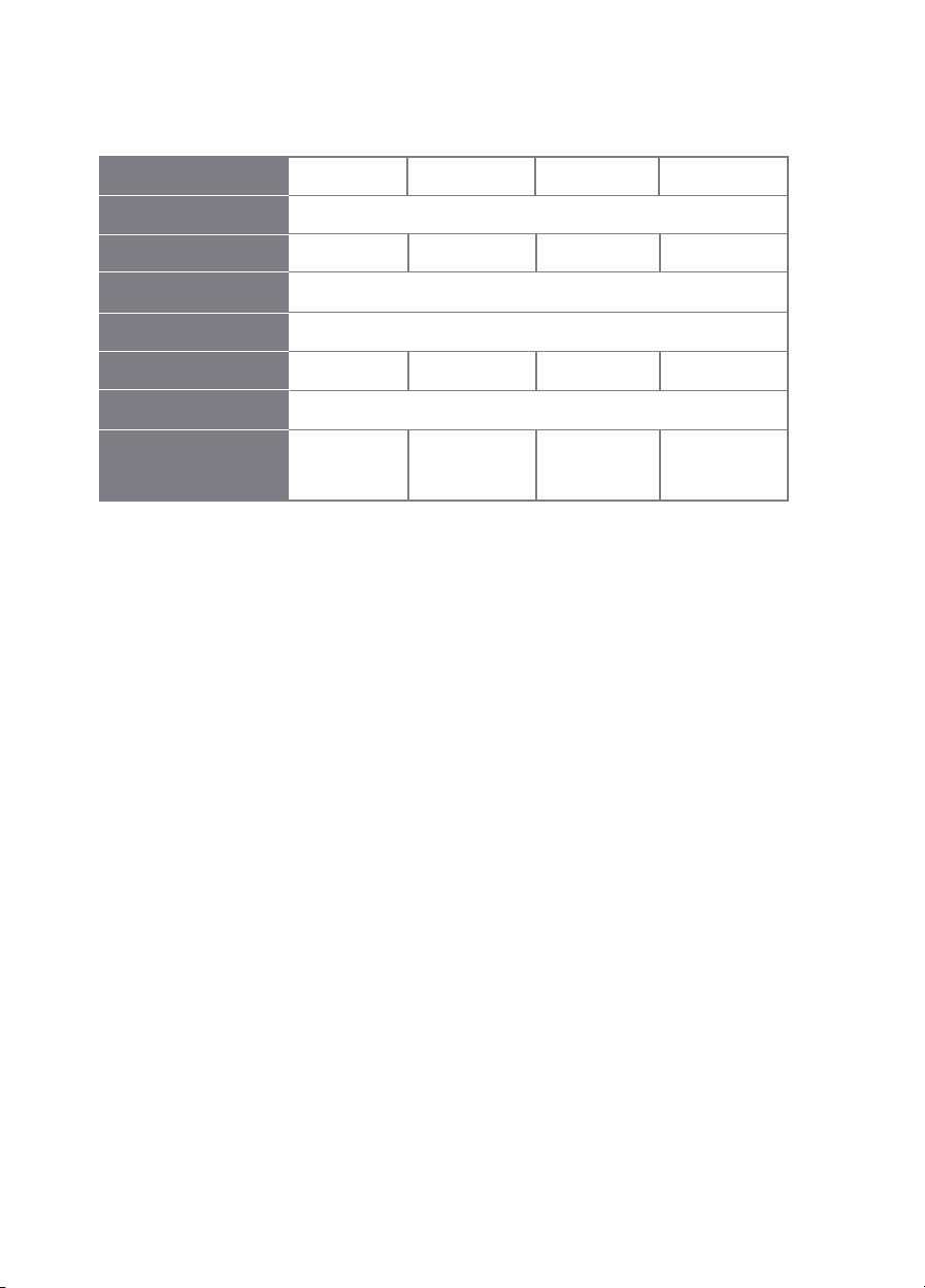
Model Identifiers: Accona panel heaters AC500T,AC1000T,AC1500T & AC2000T
Item Symbol Value Unit
AC500T AC1000T AC1500T A2000T
Heat output
Nominal heat output Pnom 0.5 1.0 1.5 2.0 kW
Minimal heat output Pmin 0.25 0.5 0.75 1.0 kW
(indicative)
Maximum continuous Pmax, c 0.5 1.0 1.5 2.0 kW
heat output
Auxiliary electricity consumption
At nominal heat elmax 0 kW
output
At minimum heat elmin 0 kW
output
In standby mode elSB 0.37 W
12
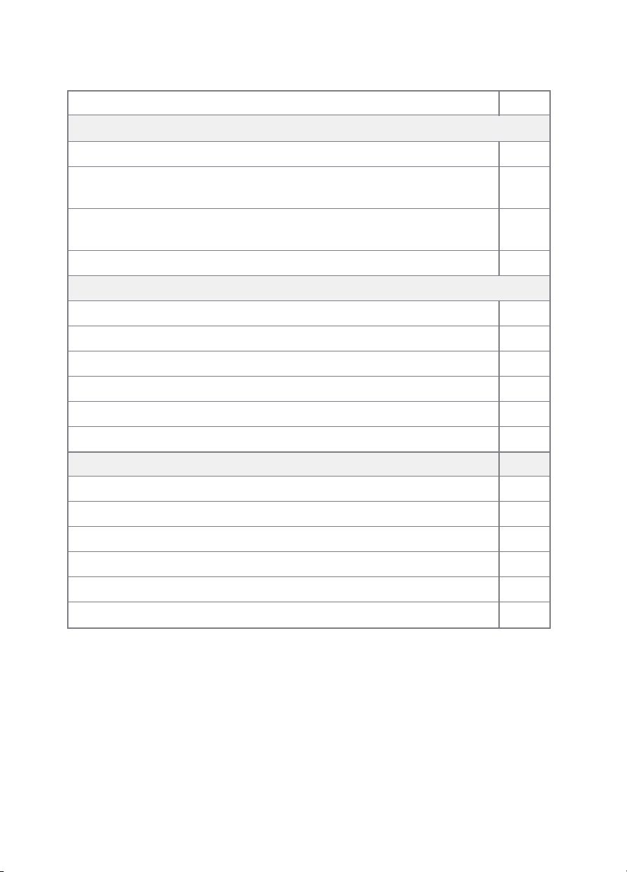
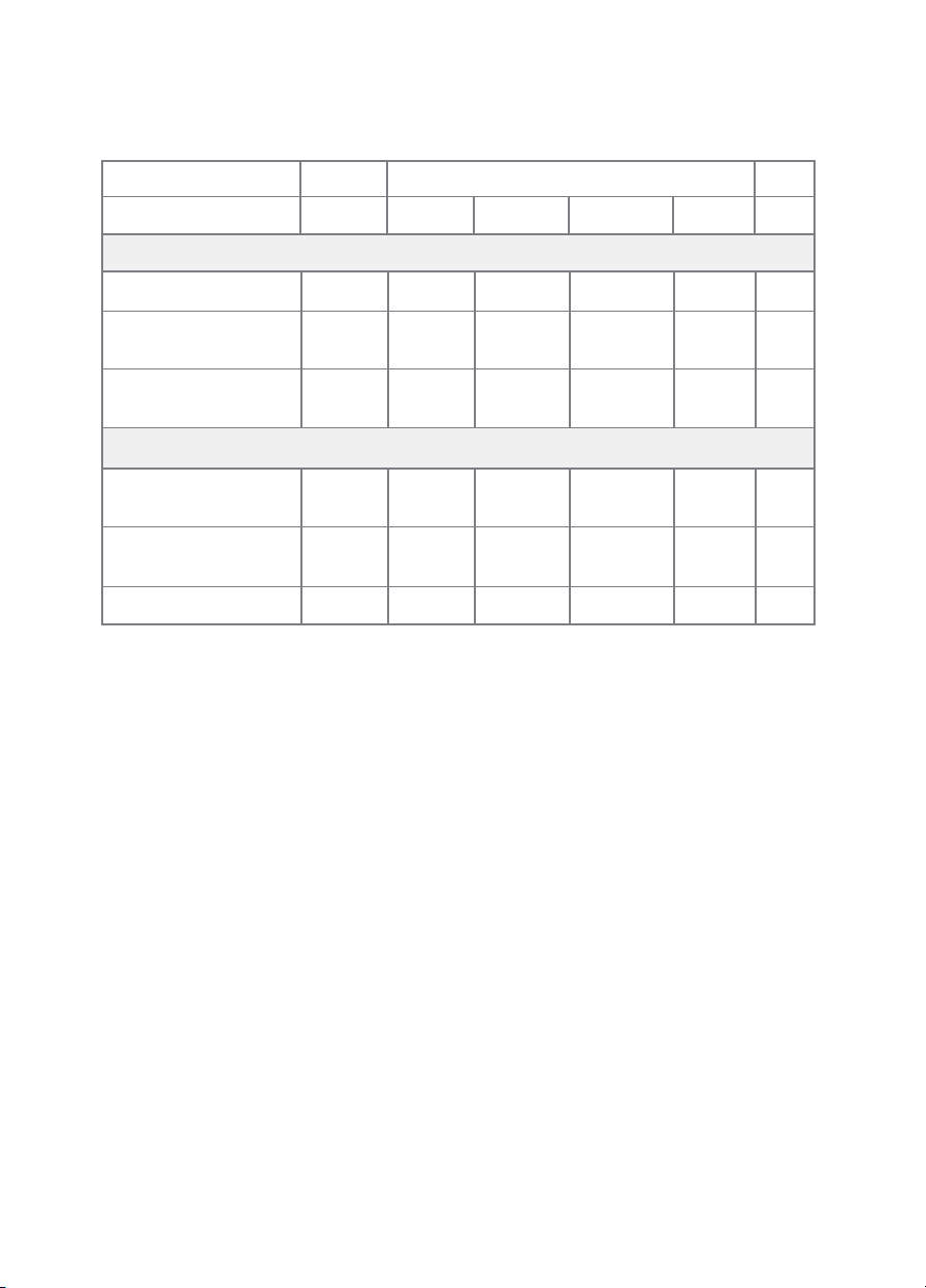
Item Unit
Type of heat input, for electric storage local space heaters (select one)
manual heat charge control with integrated thermostat No
manual heat charge control with room and/or outdoor No
temperature feedback
electronic heat charge control with room and/or outdoor No
temperature feedback
fan assisted heat output No
Type of heat output/room temperature control (select one)
single stage heat output and no room temperature control No
two or more manual stages, no room temperature control No
with mechanic thermostat room temperature control No
with electronic thermostat room temperature control No
electronic room temperature control plus day timer No
electronic room temperature control plus week timer Yes
Other control options (multiple selections possible)
room temperature control, with presence detection No
room temperature control, with open window detection Yes
with distance control option No
with adaptive start control No
with working time limitation No
with black bulb sensor No
13

6. Troubleshooting
Error codes and their meaning
E1 – Temperature sensor error
E3 – Overheat event
In the case of an E3 Overheat event the heater will beep until any button is
pressed to clear the fault. The cause of the overheat should be investigated
before continuing to use the heater.
14

7. Guarantee and service policy
This product is covered by a standard parts or replacement warranty for a period of
12 months from the date of purchase.
If there is a manufacturing defect within the warranty period we will send spare parts,
repair and return the unit or, at our discretion, supply a replacement product.
Incorrect installation and failure to follow correct operating instructions are excluded.
Consequential costs such as labour charges or damage to surroundings are expressly
excluded.
Contact us
If you experience a problem with this product you should first contact our service
department on 01924 225 200 before taking any further action.
Experience has shown that issues can often be resolved without the need to return
or uninstall the product.
15

INFORMATION FOR CORRECT DISPOSAL OF THE PRODUCT IN ACCORDANCE WITH THE
EUROPEAN DIRECTIVE 2012/19/EU.
At the end of its working life this equipment must not be disposed of as household
waste. It must be taken to a local authority waste collection centre or to a dealer
providing this service. Disposing of electrical and electronic equipment separately
enables its components to be recovered and recycled to obtain significant savings in
energy and resources. In order to underline the duty to dispose of this equipment
separately, the product is marked with a crossed out dustbin.
Hyco Manufacturing Ltd
Normandy Court
Express Way
Castleford, WF10 5NR
T 01924 225 200
F 01924 225 210
E sales@hyco.co.uk
hyco.co.uk
 Loading...