


Install Guide for
K Series Fuel Rail
This product may not be legal for highway use. Hybrid Racing is not responsible for any direct or indirect, actual
or incidental expense attributed to the use of any performance parts sold by Hybrid Racing LLC. Purchasers
agree to all of the terms of this agreement upon the purchase of parts.
Features:
Lifetime Hybrid Racing tech support at
support.hybrid-racing.com
Made from 6061 aluminum with T6 heat treatment
Durable anodized finish with a laser etched logo
1/8” NPT hole for the option of mounting a fuel pres-
sure gauge to be mounted directly to the fuel rail
Option of running a tucked fuel line kit for a cleaner
engine bay
Basic Hand Tools with
Flat head screwdriver
Package Contents:
X 1 Hybrid Racing Fuel Rail
X 2 –8 plug
X 2 –8 to –6 union
X 1 Stainless steel NPT plug
X 4 O-rings
Recommend Tools:
10mm and 12mm sockets and wrenches.
Important!! Please read the entire install guide twice before starting your instal-
lation. No, really it’s a good idea to read it twice before you begin so everything
goes smooth ;)
1
Introduction & Installation Notes
A little bit of information to make sure you have the right parts before you get started!
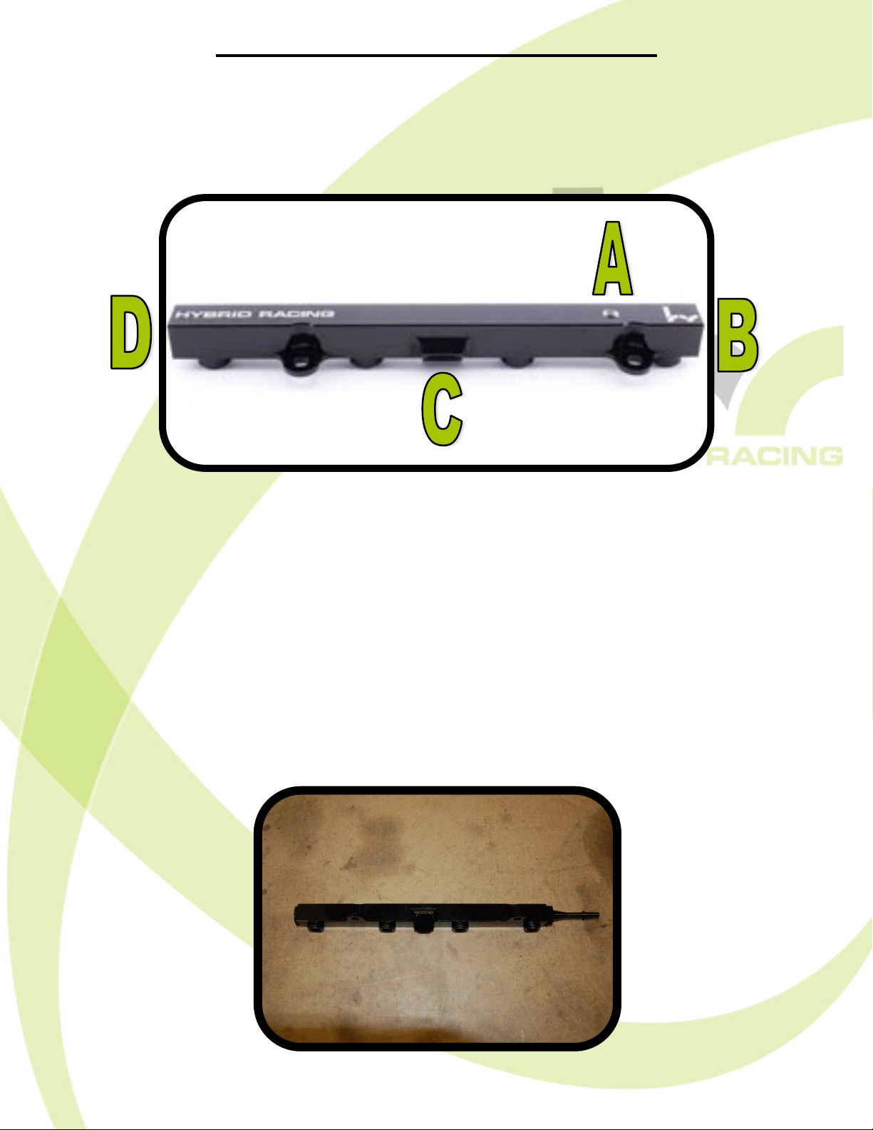
Before getting started we need to set up your fuel rail for with the correct fittings for
you fuel lines. This install guide is targeted at installing this fuel rail on a non k-swap vehicle.
If you are installing this on a k-swap vehicle, the set up of your fuel rail will be outlined in the
fuel line kit you have.
Port A: Optional to run a fuel pressure gauge here,. If you are not installing a gauge , install the stainless steel NPT plug here. Be sure to place fuel-safe sealant on the threads
whether you are running a gauge or the plug.
Port B: -8 to 5/16 quick disconnect union.
Port C: -8 AN plug.
Port D: -8 AN plug.
When set up with the correct fittings your fuel rail should appear as the one below.
2
Install Guide
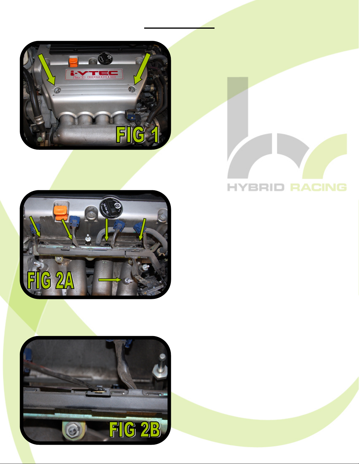
STEP 1:
Using a 10mm socket, remove
the (2) caps nuts holding the cover in place (FIG 1). Once these
are removed, pull the cover off.
This will take some force, the
cover is held on with rubber
grommets.
STEP 2A:
Unplug all (4) injector wires from
the injectors and using your
10mm socket again, remove the
ground connection from the intake manifold as illustrated in FIG
2A.
STEP 2B:
Using a flat head screwdriver, unclip the injector harness from the
fuel rail as illustrated in FIG 2B.
Once both clips are undone, slide
the harness off and set it to the
side.
3

Install Guide
STEP 3A:
Remove the cap covering the
fuel line connection as shown in
FIG 3A.
STEP 4:
Place a rag around the fuel line,
then squeeze the (2) green tabs
and pull the fuel line off as shown
in FIG 3B. Be careful when doing
so as there will likely be pressure
in the fuel line.
STEP 5:
Using a 12mm socket, remove
the (2) nuts holding the fuel rail
on and pull the fuel rail off the intake manifold as illustrated in FIG
5. Note: All 4 injectors will likely
come out with the fuel rail.
4

Install Guide
STEP 6:
Using a flathead screwdriver, pull
the clips off holding all (4) injectors in the stock fuel rail as
shown in FIG 6. Note: once you
pull one injector out, fuel is going
to flow out of the fuel rail. Make
sure you have something ready
to catch it.
STEP 7:
Remove the blue quick disconnect clip from the OEM fuel rail
and slide it onto the –8 to 5/16
quick disconnect union as illustrated in FIG 7.
STEP 8:
Install the (4) injectors into your
Hybrid Racing fuel rail. Once this
is done it should appear as the
one in FIG 8. Note: Spread some
oil on the O-ring with your finger
before installing the injectors to
help them slide in without getting
cut.
5

Install Guide
STEP 9:
Line the injectors up with the
holes on the intake manifold and
press the rail onto the intake
manifold. Using a 12mm socket,
install and tighten the (2) nuts
holding the fuel rail on. (FIG 9)
STEP 10:
Reconnect the fuel line on the
quick disconnect fitting. Do not re
-install the cover that you removed in step 3A. (FIG 10)
STEP 11:
Next we need to remove the plastic cover on the injector wiring harness so we can relocate it. Using a flat head, pry each clip apart and remove the cover as shown in FIG
11A and FIG 11B.
6

Install Guide
STEP 12:
Using a 10mm socket, remove the metal plate the MAP sensor wire is clipped to.
Then with some pliers, squeeze the clip and pull the wire off of the metal plate. (FIG
12A and FIG 12B)
STEP 14 (optional) :
Reinstall the injector cover that
was removed in step 1, or you
can leave it off and show off your
STEP 13:
Plug all (4) injectors back in.
Then, using a 10mm socket remove the cap nut on the valve
cover, relocate the injector
ground wire to that stud, and
tighten the cap nut back on top
as shown in FIG 13. Note: if the
correct wire is not on the corresponding injector the car will not
run correctly.
new Hybrid Racing fuel rail!
7

If you have any questions or comments, please email support at
support@hybrid-racing.com
Legal Disclaimer
Users assume all cost and risk associated with these or any other items purchased
from Hybrid Racing LLC.
Parts sold or manufactured by Hybrid Racing LLC may not meet legal requirements for
use on public roads. People thinking about purchasing product(s) from Hybrid Racing
LLC should check with their local and state authorities for legality. It is the user’s responsibility to know and comply with all local and federal laws and regulations. Use or
installation of Hybrid Racing LLC products may affect user insurance and/or vehicle
warranty coverage. It is the user’s sole responsibility for consequences that may occur
due to having the product installed in his/her vehicle.
Hybrid Racing LLC assumes no legal responsibilities and/or liabilities, whether to user’s vehicle, engine, person(s), and/or property(s), that result from the use of, or servicing of a vehicle of which a Hybrid Racing LLC product has been installed/attempted to
be installed, or to any other vehicle(s) and/or person(s), regardless of whether or not
this product has any involvement
directly or indirectly and/or liability, and/or whether or not proper installation has been
carried forth.
All engines, engine parts and electrical components are for OFF ROAD USE ONLY/
RACING
VEHICLES ONLY. They are not for or to be used on public roads in the USA.
Acquisition of a Hybrid Racing LLC product will act as an acknowledgement of the legal disclaimer stated herein.
Hybrid Racing LLC reserves the right to change this disclaimer at any time without any
prior
consent or notification.
Should you need to contact us our details are as follows:
Hybrid Racing LLC, 12231 Industriplex Suite B, Baton Rouge, LA 70809
www.hybrid-racing.com
8
 Loading...