

Page 1

G1-824
G2-1648
The Friendly
Digital Telephone System
ISDN Digital Telephone System
HYBR
id
EX
change
Installation &
Programming
Manual
Page 2

Notification
Notification is hereby given that Auto Telecom Company Ltd. reserves the right to modify, change, update or
revise this document from time to time as required without the prior obligation to notify any person, company or
organization. Further, Auto Telecom makes no warranty or representation, either express or implied, with
respect to merchantability, or fitness of its products for a particular purpose.
1998 Auto Telecom Company Ltd.
This document or any parts thereof are not to be reproduced or transmitted in any form or by any means,
electronic or mechanical, including photocopying, recording, or information storage and retrieval systems for
any purpose whatsoever without the express written permission of Auto Telecom Company Ltd. 26/2/2001
Issue 1.7 / May, 2002
Page 3

IMPORTANT SAFETY INSTRUCTIONS
Installation Safety Precautions:
1. Never install telephone wiring during a lightning storm.
2. Never install telephone jacks in wet locations unless the jack is specifically designed for wet
locations.
3. Never touch un-insulated telephone wires or terminals unless the telephone line has been
disconnected at the network interface.
4. Use caution when installing or modifying telephone lines.
The HYBREX G1-824 utilizes a 3-pin grounding power supply cord. This cord is not to be attached to any building
surfaces. When using your telephone equipment, basic safety precautions should always be followed to reduce the risk of
fire, electric shock and injury to persons, including the following:
1. Read and understand all instructions.
2. Follow all warnings and instruction marked on the
product.
3. Unplug this product from the wall outlet before
cleaning. Do not use liquid cleaners or aerosol
cleaners. Use a damp cloth for cleaning.
4. Do not use this product near water, for example, near
a bath tub, wash bowl, kitchen sink, or laundry tub, in
a wet basement, or near a swimming pool.
5. Do not place this product on an unstable cart, stand,
or table. The product may fall, causing serious
damage to the product.
6. Slots and openings in the cabinet and the back or
bottom are provided for ventilation, to protect it from
overheating, these openings must not be blocked or
covered. The openings should never be blocked by
placing the product on the bed, sofa, rug, or other
similar surface. This product should never be placed
near or over a radiator or heat register. This product
should not be placed in a built-in installation unless
proper ventilation is provided.
7. This product should be operated only from the type of
power source indicated on the marking label. If you
are not sure of the type of power supply to your home
or office, consult your dealer or local power company.
8. The socket-outlet shall be installed near the
equipment and shall be easily accessible.
9. This product is equipped with a three wire grounding
type plug, this plug will only fit into a grounding type
power outlet. This is a safety feature. If you are
unable to insert the plug into the outlet, contact your
electrician to replace your obsolete outlet. Do not
defeat the safety purpose of the grounding type plug.
10. Do not allow anything to rest on the power cord. Do
not locate this product where the cord will be
damaged by persons walking on it.
11. Do not overload wall outlets and extension cords as
this can result in the risk of fire or electric shock.
12. Never push objects of any kind into this product
through cabinet slots as they may touch dangerous
voltage points or short out parts that could result in
a risk of fire or electric shock. Never spill liquid of
any kind on the product.
13. To reduce the risk of electric shock, do not
disassemble this product, but take it to a qualified
service man when some service or repair work is
required. Opening or removing covers may expose
you to dangerous voltages or other risks. Incorrect
reassemble can cause electric shock when the
appliance is subsequently used.
14. Unplug this product from the wall outlet and refer
servicing to qualified service personnel under the
following conditions:
A. When the power supply cord or plug is damaged or
frayed.
B. If liquid has been spilled into the product.
C. If the product has been exposed to rain or water.
D. If the product does not operate normally by
following the operating instructions. Adjust only
those control, that are covered by the operating
instructions because improper adjustment of other
controls may result in damage and will often
require extensive work by a qualified technician to
restore the product to normal operation.
E. If the product has been dropped or the cabinet has
been damaged.
F. If the product exhibits a distinct change in
performance.
15. Avoid using a telephone (other than a cordless
type) during an electrical storm. There may be a
remote risk of electric shock from lightning.
16. Do not use the telephone to report a gas leak in the
vicinity of the leak.
SAVE THESE INSTRUCTIONS
Page 4

HYBREX G1-824
ISDN Digital Telephone System
General Description - Installation - Programming Manual
Table of Contents
NOTIFICATION.............................................................................................................................................................II
GENERAL DESCRIPTION - INTRODUCTION...........................................................................................................2
FCC RULES AND REGULATION.................................................................................................................................2
FCC R
EGISTRATION NUMBER
R
INGER EQUIVALENCE NUMBER
N
OTIFICATION OF THE TELEPHONE COMPANY
D
IRECT CONNECTION TO A PARTY-LINE OR COIN OPERATED TELEPHONE LINE IS PROHIBITED
I
NCIDENCE OF HARM TO THE TELEPHONE LINES
C
OMPATIBILITY OF THE TELEPHONE NETWORK AND TERMINAL EQUIPMENT
R
ADIO FREQUENCY INTERFERENCE
CTR 21 (98/482/EC) DECLARATION NETWORK COMPATIBILITY......................................................................4
ISDN INSTALLATION....................................................................................................................................................4
E
CONOMY AND EFFICIENCY
E
ASY INSTALLATION
E
ASY MAINTENANCE
F
LEXIBILITY OF SYSTEM APPLICATIONS
V
ARIED EXTENSION ALTERNATIVES
D
IGITAL TWIN PORT
H
YBRID PHONE
F
ISDN
ULL
L
IQUID CRYSTAL DISPLAY
M
ECHANICAL SPECIFICATIONS (KEY SERVICE UNIT
M
ECHANICAL SPECIFICATIONS (BATTERY BACK UP HOUSING
E
NVIRONMENTAL SPECIFICATIONS
FEATURES.......................................................................................................................................................................9
S
YSTEM FEATURES
S
TATION FEATURES
PARTS & PERIPHERALS............................................................................................................................................12
YSTEM MODULES
S
YPE OF PHONES
T
ERIPHERAL DEVICES
P
PTIONAL INTERFACE CARDS
O
SYSTEM INSTALLATION - INTRODUCTION .........................................................................................................13
FEATURES
........................................................................................................................................................6
.......................................................................................................................................................6
........................................................................................................................................................6
................................................................................................................................................................6
..........................................................................................................................................................9
.......................................................................................................................................................11
............................................................................................................................................................12
...............................................................................................................................................................12
........................................................................................................................................................12
..........................................................................................................................................2
.......................................................................................................................................2
...................................................................................................................2
............................................2
................................................................................................................2
.......................................................................4
...................................................................................................................................4
.............................................................................................................................................5
............................................................................................................................6
.................................................................................................................................6
......................................................................................................................................................7
...............................................................................................................................................7
) .........................................................................................................8
)...........................................................................................8
....................................................................................................................................8
..............................................................................................................................................12
SITE REQUIREMENTS................................................................................................................................................14
L
OCATION
Choosing the Right Environment...............................................................................................................................14
I
NSTALLATION CHECKLIST
Issue 1.7 / May, 2002
.....................................................................................................................................................................14
.............................................................................................................................................14
Page 5

EQUIPMENT REQUIREMENTS.................................................................................................................................14
INSTALLATION............................................................................................................................................................15
I
NSTALLING EXPANSION AND OPTIONAL CARDS
G1-CFC- Conference Card.......................................................................................................................................16
G1-MSC- Multi Service Card ....................................................................................................................................16
G1-VSC- Voice Service Card ....................................................................................................................................16
G1-TKU- 4 Port CO Line Card................................................................................................................................17
G1-CIC- Caller ID Card...........................................................................................................................................17
G1-SIU ISDN S/T Interface Card..............................................................................................................................18
G1-STC Digital Station Adapter Card .......................................................................................................................19
G1-SLC Single Line Station Adapter Card................................................................................................................20
G1-RGU - Ring Generator Unit (for G1-SLC)...........................................................................................................20
G1-RGU1 - Ring Generator Unit (for G1-SLC1 (CLIP version)) ...............................................................................21
Voltage Selection Check............................................................................................................................................21
I
NSTALLING THE EQUIPMENT
Backboard ................................................................................................................................................................22
Key Service Unit.......................................................................................................................................................22
P
OWER SUPPLY
P
REPARING THE EXTERNAL BATTERY BACKUP
C
HARGING THE BATTERY
I
NSTALLING OR REPLACING BATTERIES
Caution .....................................................................................................................................................................23
S
YSTEM GROUND
KSU C
ONNECTING (MAIN
C
ONNECTING STATIONS
D
IGITAL KEY TELEPHONE
D
IGITAL KEY TELEPHONE
A
CCESS CONTROL TELEPHONE
S
INGLE LINE TELEPHONE (CONNECTED TO
D
OOR PHONE CONNECTION
S
INGLE LINE TELEPHONE (CONNECTED TO
CO/PABX C
ISDN S/T C
OPTIONAL CABLING..................................................................................................................................................33
D
OOR SWITCH (RELAY
S
ENSOR CONNECTION
P
AGING CONNECTION
M
USIC ON HOLD CONNECTION
RS232 P
POWER ON AND OPERATIONAL TEST...................................................................................................................35
O
PERATIONAL TESTS
SPECIAL IMMUNITY PROTECTION FOR SYSTEM AND TERMINALS .............................................................35
M
ECHANICAL SPECIFICATIONS (KEY SERVICE UNIT
M
ECHANICAL SPECIFICATIONS (BATTERY BACK UP HOUSING
E
NVIRONMENTAL SPECIFICATIONS
PARTS & PERIPHERALS ............................................................................................................................................38
S
YSTEM MODULES
T
YPE OF PHONES
P
ERIPHERAL DEVICES
O
PTIONAL INTERFACE CARDS
SYSTEM INSTALLATION - INTRODUCTION .........................................................................................................40
..............................................................................................................................................................22
...........................................................................................................................................................23
ONNECTIONS
ONNECTIONS
ORT CONNECTION
.........................................................................................................................................................38
............................................................................................................................................................38
..........................................................................................................................................22
...............................................................................................................................................23
) P
ANEL LAYOUT
.................................................................................................................................................24
– DK1-21/22/31/33 ...............................................................................................................25
– DK1-21H............................................................................................................................26
– ACP............................................................................................................................27
............................................................................................................................................28
..............................................................................................................................................30
...............................................................................................................................................30
) C
ONNECTION
....................................................................................................................................................33
....................................................................................................................................................33
.......................................................................................................................................33
.............................................................................................................................................34
.....................................................................................................................................................35
..................................................................................................................................38
.....................................................................................................................................................39
.........................................................................................................................................39
................................................................................................................15
................................................................................................................22
...........................................................................................................................23
....................................................................................................................23
G1-SLC) .......................................................................................................28
DK-SLD) ......................................................................................................29
............................................................................................................................33
)........................................................................................................38
).........................................................................................38
Page 6

INSTALLATION............................................................................................................................................................41
I
NSTALLING THE EQUIPMENT
Backboard ................................................................................................................................................................41
Key Service Unit.......................................................................................................................................................41
P
OWER SUPPLY
I
NSTALLING EXPANSION AND OPTIONAL CARDS
G2-IPU.....................................................................................................................................................................43
1.) SW1: Reset button .........................................................................................................................................43
G2-MSU- Multi Service Card....................................................................................................................................44
1.) JP1: Grounding Jumper for some specific external paging device.................................................................44
G2-VSC- Voice Service Card.................................................................................................................................... 45
G2-STU Digital Station Card ....................................................................................................................................45
G2-SLU Analog Station Card....................................................................................................................................46
G2-TKU- 4 Port CO Line Card................................................................................................................................46
G2-CIC- Caller ID Card...........................................................................................................................................47
G2-SIU ISDN S/T Interface Card..............................................................................................................................48
G2-PIU ISDN PRI / T1 / E1 Interface Card ..............................................................................................................49
Voltage Selection Check ...........................................................................................................................................49
P
REPARING THE EXTERNAL BATTERY BACKUP
C
HARGING THE BATTERY
I
NSTALLING OR REPLACING BATTERIES
Caution.....................................................................................................................................................................50
S
YSTEM GROUND
C
ONNECTING STATIONS
POWER ON AND OPERATIONAL TEST ..................................................................................................................52
O
PERATIONAL TESTS
SPECIAL IMMUNITY PROTECTION FOR SYSTEM AND TERMINALS .............................................................52
P
ROGRAMMING INFORMATION
New Systems .............................................................................................................................................................54
Basic Programming Commands:...............................................................................................................................55
Alphanumeric Entry:.................................................................................................................................................56
PROGRAM 01-TK-IP : DAY RINGING AND RINGING LINE PREFERENCE ASSIGNMENT........................... 58
..............................................................................................................................................................41
...........................................................................................................................................................51
..........................................................................................................................................41
................................................................................................................41
................................................................................................................50
...............................................................................................................................................50
...........................................................................................................................50
.................................................................................................................................................51
.....................................................................................................................................................52
........................................................................................................................................54
PROGRAM 02-TK-IP : NIGHT RINGING AND RINGING LINE PREFERENCE ASSIGNMENT...................... 58
PROGRAM 03-01-IP : DOOR PHONE RINGING ASSIGNMENT...........................................................................59
PROGRAM 04-GP-IP : CONSOLE ASSIGNMENT...................................................................................................59
PROGRAM 05-01-IP : SYSTEM TIMING PARAMETERS – 01...............................................................................60
01. H
OLD RECALL TIME
02. E
XCLUSIVE HOLD RECALL TIME
03. H
OLD RECALL TIMEOUT
04. DISA A
05. B
06. P
07. DTMF G
08. C
PROGRAM 05-02-IP : SYSTEM TIMING PARAMETERS – 02...............................................................................62
01. SLT D
02. SLT I
Issue 1.7 / May, 2002
CCESS DELAY TIME
USY REMIND CYCLE TIME (OFF-HOOK RINGING
AUSE TIME
ENERATION TIME
ALL FORWARD NO ANSWER TRANSFER TIME
IAL TONE TIMEOUT
NTER-DIGIT TIMEOUT
:.................................................................................................................................................60
:...............................................................................................................................60
:.......................................................................................................................................... 60
: ....................................................................................................................................60
): ...................................................................................................61
:............................................................................................................................................................61
:......................................................................................................................................61
:.........................................................................................................61
:.......................................................................................................................................62
:.................................................................................................................................... 62
Page 7

03. A
UTO REDIAL RINGING TIME
04. SLT R
05. E
06. SLT H
07. R
08. R
ELEASE SIGNAL
XCHANGE LINE FLASH TIME
OLD SIGNAL
ING ON TIME
ING OFF TIME
:........................................................................................................................................................63
:.......................................................................................................................................................63
: .................................................................................................................................................63
– PSTN
: ............................................................................................................62
LINES
:.............................................................................................................................................62
- K
EY PHONE
& A
NALOGUE PHONE
: ............................................................................63
PROGRAM 05-03-IP : SYSTEM TIMING PARAMETERS – 03...............................................................................64
01. M
AKE/BREAK RATIO
02. A
UTOMATIC TRUNK SEARCH
03. I
NTERCOM CALL SIGNALLING METHOD
04. PABX (C
05. T
OLL ACCESS CODE
06. S
TATION NUMBERING PLAN
07. I
NTERCOM DIAL TONE PATTERN
08. D
ENTREX
OOR PHONE RING PATTERN
:...............................................................................................................................................64
:...................................................................................................................................64
: ...................................................................................................................64
) O
UTGOING CODE
: (R
EFER TO PROGRAM
35-TK-01):....................................................................64
:................................................................................................................................................65
: ....................................................................................................................................65
:..............................................................................................................................65
:...................................................................................................................................65
PROGRAM 05-04-IP : SYSTEM TIMING PARAMETERS – 04...............................................................................66
01. S
YSTEM BAUD RATE SETTING
02. D
03. A
04. 12/24 H
06. S
07. S
08. M
9 F
IAL
CTION FOR CALL DURATION LIMITING
PEED DIALLING DISTRIBUTION
INGLE DIGIT INTERCOM
ESSAGE WAITING METHOD FOR ANALOGUE PHONES
:...........................................................................................................................................................66
LAG
OURS CLOCK
: ..............................................................................................................................................66
: .................................................................................................................................66
:...................................................................................................................66
:...............................................................................................................................67
:.........................................................................................................................................67
: .............................................................................................67
PROGRAM 05-05-IP : SYSTEM TIMING PARAMETERS – 05...............................................................................68
01. M
ORNING CALL
02. M
ETERING DETECTOR
03, 04. S
05. N
06. D
07. A
08. A
PEED DIAL UNRESTRICTED
AME FUNCTION
IAL TONE DETECTION
UTO REDIAL TIMES
UTO REDIAL PAUSE TIME
:......................................................................................................................................................68
:.............................................................................................................................................68
1, 2:........................................................................................................................68
: ....................................................................................................................................................69
:...........................................................................................................................................69
:...............................................................................................................................................69
:......................................................................................................................................69
PROGRAM 05-06-IP : SYSTEM TIMING PARAMETERS – 06...............................................................................70
01. T
RANSFER BUSY RECALL TIMEOUT
02. T
RANSFER IDLE RECALL TIMEOUT
03. ISDN A
04. P
OLARITY REVERSAL
05. O
PERATOR CODE
06. U
NSUPERVISED CONFERENCE AND
07. H
OLD FEATURE FOR
08. S
TATION HUNTING GROUP RING METHOD
...........................................................................................................................................................70
UDIO
: ..............................................................................................................................................70
: ....................................................................................................................................................71
SLT:.........................................................................................................................................71
:..........................................................................................................................70
: ...........................................................................................................................70
ECF T
IME SETTING
:.............................................................................................71
:................................................................................................................71
PROGRAM 05-07-IP : SYSTEM TIMING PARAMETERS – 07...............................................................................72
01. I
NTERCOM SEARCHING
02. T
OLL OVERRIDE PREVENTION FROM QUICK DIAL
03. R
ESERVED
04. DISA R
05. T
OLL RESTRICTION OVERRIDE PREVENTION
06. SMDR D
07. M
ETER PULSE DETECT DELAY TIME
08. R
ESERVED
...............................................................................................................................................................72
ECALL TO CONSOLE
IGIT MASK
...............................................................................................................................................................73
:............................................................................................................................................72
: ......................................................................................................72
- NO D
: ............................................................................................................72
IALLING
:.............................................................................................................73
:................................................................................................................................................73
(CO
RELEASE GUARD TIME
): ..............................................................................73
PROGRAM 05-08-IP : SYSTEM TIMING PARAMETERS – 08...............................................................................74
01. R
ING HUNT TIME SETTING
: ......................................................................................................................................74
Page 8

02. DSS A
03. SLT C
04. DISA T
05. SLT P
06. DISA T
07. DISA T
08. M
CCESS TO OTHER TRUNK GROUP
AMP ON TONE
RANSFER GROUP
ROGRAMMING DIGIT
RANSFER TIME NO ANSWER
RANSFER TIME NO DIALLING
USIC SOURCE SELECTION
: ..............................................................................................................................................74
:.........................................................................................................................................74
:......................................................................................................................................75
.......................................................................................................................................75
: ...................................................................................................................74
: ........................................................................................................................75
:.......................................................................................................................75
PROGRAM 05-09-IP : SYSTEM TIMING PARAMETERS – 09...............................................................................77
01. R
ESERVED
02. C
ONSOLE QUEUING
03. C
LEAR FORWARD SIGNAL DETECTION
04. DISA B
06. ACD-1 E
07. ACD-1 S
08. ACD-1 R
...............................................................................................................................................................77
:.................................................................................................................................................77
USY TONE DETECTION
NABLE TIME
EGMENT
ELEASE TIME
:.............................................................................................................................................78
2 R
ECALL TIME
:............................................................................................................................................78
- L
OOP DISCONNECT
: ................................................................................................................................77
:...........................................................................................................................78
.......................................................................................77
PROGRAM 05-10-IP : SYSTEM TIMING PARAMETERS – 10...............................................................................79
PROGRAM 05-11-IP : SYSTEM TIMING PARAMETERS – 11...............................................................................81
01. R
ESERVED
02. N
UMBER OF
03. S
ELECT MUSIC ON HOLD OR RING BACK TONE
04. DISA P
05: DISA S
06. DISA RE-
07. D
OOR PHONE RINGING TIME
08. DISA S
...............................................................................................................................................................81
DISA P
ASSWORDS
: ...............................................................................................................................81
:.........................................................................................................81
ROCESSING WAY WHEN
PECIAL FUNCTION ACCESS
CHECK TIMES TO STATION/CONSOLE
VSU
IS BUSY OR ABSENT
:........................................................................................................................... 82
:........................................................................................................82
:.........................................................................................81
: ...................................................................................................................................82
INGLE DIGIT DIALLING
:................................................................................................................................82
PROGRAM 05-12-IP : SYSTEM TIMING PARAMETERS – 12...............................................................................83
01. C
ALL TRANSFER METHOD
02. R
ESERVED
03. E
XCLUSIVE HOLD CAPABILITY
04. D
OOR UNLOCK RELAY ACTIVATION TIME
05. V
OICE MAIL CALL FORWARD PROTOCOL SELECTION AND MUTING LEADING DIGITS
07. LED
08. A
NALOGUE
...............................................................................................................................................................83
INDICATION OF CHECK IN
CO L
INE DETECTION
– K
EY TELEPHONE
:..........................................................................................................83
:.................................................................................................................................83
:................................................................................................................83
..................................................84
/ C
HECK OUT
: (F
:............................................................................................................84
U01GX/E01G
OR
X VERSION ONLY
).................................................................... 84
PROGRAM 05-13-IP : SYSTEM TIMING PARAMETERS – 13...............................................................................85
01. I
NTERCOM HOT KEY DIALLING
02. I
MMEDIATE
03. C
ALLER
06. CTI-T
07. L
EAST COST ROUTING
08. L
EAST COST ROUTING
SMDR
ID B
UFFER BLOCK SIZE
RUNK STATUS REPORT
OUTPUT
:................................................................................................................................85
......................................................................................................................................85
...............................................................................................................................85
....................................................................................................................................86
– W
EEKLY HOLIDAY
– W
EEKLY HOLIDAY
1...........................................................................................................86
2...........................................................................................................86
PROGRAM 05-14-IP : SYSTEM TIMING PARAMETERS – 14...............................................................................87
01. ISDN R
ECOVERY
02. G2-PIU C
G2-PIU C
ARD TYPE
03. ISDN PRI T
04. MDC M
ETER PULSE DETECTING FREQUENCY
05. ISDN CLI S
06. ACP C
ASE OPEN ALARM
07, 08. MDC M
(G1-824)......................................................................................................................................87
ARD TYPE
:................................................................................................................................................87
: .....................................................................................................................................................87
: .....................................................................................................................................................87
YPE
:..........................................................................................................88
......................................................................................................................................................88
END
..........................................................................................................................................88
ETER PULSE DETECTION GAIN SENSITIVITY
: ...........................................................................................88
Issue 1.7 / May, 2002
Page 9

PROGRAM 05-15-IP : SYSTEM TIMING PARAMETERS – 15...............................................................................89
01. E
05. ISDN P
06. ISDN P
PROGRAM 05-16-IP : SYSTEM TIMING PARAMETERS – 16...............................................................................91
07. O
08. ISDN E
PROGRAM 06-IP : RELAY ASSIGNMENT...............................................................................................................93
XTENDED
UTPUT ACCESS CONTROL DATA
VMU S
RIMARY RATE TRUNK NUMBERS
RIMARY RATE TRUNK NUMBERS
VENT MONITOR
:.................................................................................................................................89
ERVICE
:............................................................................................................................91
: ..........................................................................................................................................91
A:.............................................................................................................89
B: .........................................................................................................89
PROGRAM 07-GP-IP : FLEXIBLE KEY GROUP ASSIGNMENT..........................................................................94
PROGRAM 08-GP-IP : FLEXIBLE DSS CONSOLE KEY GROUP ASSIGNMENT...............................................97
PROGRAM 09-NNN-DP : SYSTEM SPEED DIAL.....................................................................................................98
PRE-A
SSIGNED
T
ELEPHONE NUMBER
PROGRAM 10-GP-IP : INTERCOM OR DISA SINGLE DIGIT ASSIGNMENT....................................................99
PROGRAM 11-IP : DATE AND TIME SETTING .................................................................................................... 100
PROGRAM 12-NN : SYSTEM ALARM CLOCK..................................................................................................... 100
PROGRAM 13-NN : PASSWORD .............................................................................................................................101
PROGRAM 14-01-IP : SMDR SPECIFICATIONS ...................................................................................................102
01. C
ALL DURATION START TIME
02. R
ECORD INCOMING CALLS
03. R
ECORD LOCAL CALLS
04. R
ECORD INCOMING CALLS NO ANSWER
05. P
RINT OUT THE TITLE
06. N
UMBER OF RECORDS BETWEEN THE TITLE
07. R
ESERVED
08. P
OLARITY REVERSAL
PROGRAM 17-NN : FORCED ACCOUNT CODE................................................................................................... 106
CO L
: ............................................................................................................................................................103
:...............................................................................................................................................98
INE
:....................................................................................................................................................98
:.................................................................................................................................102
: ....................................................................................................................................102
:.......................................................................................................................................... 102
:.................................................................................................................102
:............................................................................................................................................ 102
: ............................................................................................................103
: ............................................................................................................................................103
PROGRAM 18-NN-TK : ASSIGN TOLL PLANS TO TRUNK LINES ...................................................................107
PROGRAM 19-CN-IP : VOICE SERVICE (VSC) ASSIGNMENT-G1 824............................................................. 108
PROGRAM 20-NN- : SET DAY – TIME / LUNCH TIME SCHEDULE...............................................................110
PROGRAM 25 : RESET DATA TO SYSTEM DEFAULT.......................................................................................111
PROGRAM 29-TK-IP : TRUNK SPECIFICATIONS – 2......................................................................................... 112
01. CO L
02. ACD-1 F
03. ISDN I
04. S
05. A
06. USA 1A2 E
07. CO D
08. CO D
INE LOOP RESISTANCE AUDIO BOOST
UNCTION ENABLE
NCOMING CALL TYPE
ET RING FREQUENCY
LLOW AUDIBLE RING FOR INCOMING CALLS
MULATION
ELAYED RING TIMER TO HUNTING GROUP
ELAYED RING OVERFLOW HUNTING GROUP
(DK
:..........................................................................................................................................113
: ...........................................................................................................112
: ...................................................................................................................................112
..................................................................................................................................112
HANDSETS
): .................................................................................................................113
:........................................................................................................ 113
:.....................................................................................................113
:...................................................................................................113
Page 10

PROGRAM 35-TK-IP : TRUNK SPECIFICATIONS – 1.........................................................................................114
01. T
RUNK TYPE
02. T
RUNK SIGNAL
03. E
XTERNAL CALL FORWARD
04. DISA/ECF (D
05. P
ICK UP
06. L
OUD BELL
07. I
NWARD LINE RINGING METHOD ASSIGNMENT (DAY
08. I
NWARD LINE RINGING METHOD ASSIGNMENT (NIGHT
T
O SET AN TRUNK NAME
PROGRAM 36-GP-TK : TRUNK GROUP ASSIGNMENTS...................................................................................117
:.........................................................................................................................................................114
:..................................................................................................................................................... 114
- ECF:.........................................................................................................................114
IRECT INWARD SYSTEM ACCESS/EXTERNAL CALL FORWARD
:................................................................................................................................................................115
:...........................................................................................................................................................115
): ............................................................................................115
): .........................................................................................116
-.............................................................................................................................................116
):...........................................................114
PROGRAM 37-TK : BUSY OUT TRUNKS ..............................................................................................................118
PROGRAM 38-GP-TK : DIAL 87 TRUNK GROUP ASSIGNMENTS....................................................................119
PROGRAM 39-IP : SENSOR ASSIGNMENTS.........................................................................................................120
PROGRAM 40-ST-IP : STATION CLASS OF SERVICE – 1 ..................................................................................122
01. O
VERRIDE LEVEL
02. M
ONITOR LEVEL
03: L
IMIT CALL DURATION
04. S
TATION LOUD BELL
05. A
CCESS PAGING
06. BE P
07. S
08. F
PROGRAM 41-ST-IP : STATION SPECIFICATIONS ............................................................................................124
01. S
02. F
03. S
04. D
05. T
06. T
07. P
PROGRAM 42-ST-IP : REGISTER MEMORY BLOCK FOR INDIVIDUAL SPEED DIAL ................................126
AGED
ECURITY CODE STATUS
ORCED ACCOUNT CODE
TATION GROUP
LEXIBLE KEY PATTERN GROUP ASSIGNMENTS (KEY PHONE
HIFT KEY GROUP FOR KEYPHONE
IAL 9 TRUNK GROUP
OLL PLAN
OLL PLAN
ORT NUMBER
:..................................................................................................................................................122
:................................................................................................................................................... 122
: ..........................................................................................................................................122
:.............................................................................................................................................123
:.................................................................................................................................................... 123
:.............................................................................................................................................................123
:........................................................................................................................................123
:........................................................................................................................................123
:....................................................................................................................................................124
):....................................................................................124
/ SLT P
:............................................................................................................................................125
- DAY: .................................................................................................................................................125
- N
: ..............................................................................................................................................125
IGHT
: ......................................................................................................................................................125
ORT AS
MOH S
:...........................................................................124
OURCE
PROGRAM 43-CN-IP : PORT SPECIFICATIONS.................................................................................................. 127
01. S
TATION NUMBER
02. E
QUIPMENT TYPE
03. F
LEXIBLE KEY PATTERN GROUP ASSIGNMENTS
04. D
ISALLOW
05. V
OICE MAIL BOX CAPACITY
T
O SET AN EXTENSION NAME
PROGRAM 44-ST-IP : STATION CLASS OF SERVICE – 2 ..................................................................................130
01. S
YSTEM ALARM
02. H
OLD FEATURE
03. C
ALL SPLIT
04. M
ANUAL LINE
05. H
EADSET FEATURE
06. U
SE ENGINEERING PASSWORD
Issue 1.7 / May, 2002
:................................................................................................................................................. 127
:..................................................................................................................................................127
SLT C
ONNECTION
:.................................................................................................................................................... 130
:.....................................................................................................................................................130
:...........................................................................................................................................................130
: ......................................................................................................................................................131
:................................................................................................................................................131
:............................................................................................................................... 128
(G2-VMU):................................................................................................................ 128
- ......................................................................................................................................129
:...............................................................................................................................131
(DSS
CONSOLE
):...............................................................................128
Page 11

07. DTMF R
08. S
PROGRAM 45-ST-IP : STATION CLASS OF SERVICE – 3...................................................................................132
01. I
NTERCOM CALL LIMITATION
02. R
03. R
04. A
05. I
NTERCOM CALLS TO DIFFERENT STATION GROUPS
06. R
07. A
08. R
PROGRAM 46-ST-IP : STATION CLASS OF SERVICE – 4...................................................................................134
01. D
02. M
03. A
04. DISA/ISDN I
05. M
06. D
07. ACP D
08. ACP F
PROGRAM 47-ST-IP : HOT LINE ASSIGNMENT .................................................................................................136
ECEIVER CONTROL FOR VOICE MAIL PORTS
TATION ALARM SIGNAL
ESERVED
INGING VOLUME UP GRADUALLY CAPABILITY
LLOW TRUNK ACCESS
ECEIVE BREAK ALARM
LLOW UNRESTRICTED SPEED DIAL ACCESS
ECORD STATION'S
IAL
ESSAGE WAITING LEVEL
UTOMATIC ANSWER CAPABILITY (KEYPHONE
AXIMUM RE-TRANSFERRED TIMES
OOR UNLOCK
.............................................................................................................................................................132
[87] T
RUNK GROUP
NDIAL RECALL CAPABILITY
/DND/CFWD A
OOR PHONE HUNT GROUP/PERMANENT CALL FORWARD GROUP
UNCTION SETTINGS
:.......................................................................................................................................131
:................................................................................................................................ 132
:......................................................................................................................................... 132
:........................................................................................................................................133
SMDR D
: ......................................................................................................................................134
:..........................................................................................................................133
ATA
: ....................................................................................................................................134
:..............................................................................................................135
:......................................................................................................................135
: ...................................................................................................................135
CCESS
/ SLT R
ING CADENCE SETTINGS
:.............................................................................................. 131
:..................................................................................................... 132
:................................................................................................132
:..........................................................................................................133
) / I
NTERNAL
CLIP(C
:.................................................................................... 135
ID)
ALLER
: ..................................................................135
FUNCTION
:......................................134
PROGRAM 50-ST-IP : STATION CLASS OF SERVICE – 5...................................................................................138
01. ACP W
02. R
03. ISDN I
04. CTI-E
05. VMS L
06. . ACP D
07. ACP D
08. ACP P
PROGRAM (51 TO 59)-CODE-IP : TOLL PLANS – ALLOWED DIGITS – CLASS 1 TO 9 ................................140
PROGRAM (61 TO 66)-CODE-IP : TOLL PLANS – RESTRICTED DIGITS – CLASS 1 TO 6...........................141
PROGRAM 67-GP-IP : HUNT GROUP PILOT NUMBER......................................................................................143
01. H
02. H
PROGRAM 68-GP-IP : HUNT GROUP ASSIGNMENT – DAY..............................................................................144
PROGRAM 69-GP-IP : HUNT GROUP ASSIGNMENT – NIGHT........................................................................145
PROGRAM 70-CD-IP : ISDN INTERFACE SPECIFICATIONS PROGRAM – G1-824....................................... 146
PROGRAM 70-CD-IP : ISDN(BRI/PRI) INTERFACE SPECIFICATIONS PROGRAM G2-1648....................... 147
ARNING SIGNALS
ESERVED
UNTING GROUP PILOT NUMBER
UNTING GROUP RINGING METHOD
: ............................................................................................................................................................138
NCOMING CALL DISPLAY TYPE
XTENSION STATUS REPORT
EADING DIGITS FOR INTERCOM CALLS
OOR UNLOCK RELAY
OOR OPEN CONTROL
HONE OPERATION TYPE
:.......................................................................................................................................138
:...................................................................................................................138
:..........................................................................................................................138
:........................................................................................................139
:................................................................................................................................139
...................................................................................................................................139
: ..............................................................................................................................139
:...........................................................................................................................143
: ......................................................................................................................143
PROGRAM 72-ST : ISDN CALLED PARTY EXTENSION NUMBER ASSIGNMENT.......................................149
PROGRAM 73-ST : ISDN EXTENSION SUB-ADDRESS ASSIGNMENT ............................................................149
PROGRAM 75-NUM-IP : LCR - ANALYSIS TABLE..............................................................................................150
Page 12

PROGRAM 76-NUM-TM : LCR – ROUTING TABLE............................................................................................151
PROGRAM 77-NUM : LCR – MODIFYING TABLE..............................................................................................153
PROGRAM 78-ST-IP : STATION CLASS OF SERVICE – 6 ..................................................................................154
01. LCR R
02. LCR – D
06. USA 1A2 E
PROGRAM 83-ST-IP : REGISTER MEMORY BLOCK FOR CLI HISTORY BUFFER..................................... 156
PROGRAM 84-IP : HOME AREA CODE.................................................................................................................157
PROGRAM 85-NN-IP : OVERLAY AREA CODE...................................................................................................157
PROGRAM 86-NNN-IP : OFFICE CODE REDIAL PATTERN..............................................................................158
PROGRAM 87-CN-IP : ASSIGN DOORPHONE FOR KEY CARD .......................................................................160
PROGRAM 88-DP : REGISTER KEY CARD ..........................................................................................................160
PROGRAM 89-CN-IP : DELETE KEY CARD.........................................................................................................161
PROGRAM 91-TM : ACP TIME LOCK – ASSIGN TIME...................................................................................... 162
PROGRAM 92-CN : ACP TIME LOCK – ASSIGN CARD...................................................................................... 162
PROGRAMMING CROSS REFERENCE..................................................................................................................163
OUTING LEVEL
IRECT ACCESS A TRUNK
MULATION (STATION PROGRAMMING
............................................................................................................................................154
............................................................................................................................154
):................................................................................................. 154
INCOMING CALLS ....................................................................................................................................................163
OUTGOING CALLS....................................................................................................................................................163
INTERCOM CALLS....................................................................................................................................................164
BUSY/DURING CONVERSATION ............................................................................................................................164
DISA..............................................................................................................................................................................165
NIGHT SERVICE........................................................................................................................................................165
GROUP ASSIGNMENTS ............................................................................................................................................165
CALL CONTROL ........................................................................................................................................................165
SYSTEM CLOCK........................................................................................................................................................166
STATION NUMBERING ............................................................................................................................................166
SINGLE LINE TELEPHONE .....................................................................................................................................166
MISCELLANEOUS .....................................................................................................................................................167
OPTIONAL SERVICES...............................................................................................................................................167
VOICE MAIL INTEGRATION ..................................................................................................................................167
Issue 1.7 / May, 2002
Page 13

Page 14

Page 15

G1-824 - General Description
1
Page 16
(c) Inform the customer of the right to bring a complaint to the FCC pursuant to the procedures
General Description - Introduction
The General Description section contains an easy to understand overview of the HYBREX® G1-824 ISDN
Digital Telephone System. It is the intent of this document to provide both technical and non-technical readers
with information pertaining to the system building blocks, capabilities, key highlights, electrical, physical and
environmental characteristics of the HYBREX G1-824 ISDN Digital Telephone System.
FCC Rules and Regulation
In compliance with the requirements of Part 68of the Federal Communications Commission Rules and
Regulations for connection of terminal system equipment to the telephone network and for your convenience,
the following information is presented.
FCC Registration Number
The HYBREX G1-824 is registered with the FCC in a dual registration capacity enabling the system to operate
as a key system only or as a hybrid system. The FCC Registration Numbers are 3A7TAI-35152-KF-E for key
systems registration and 3A7TAI-36015-MF-E for hybrid operation.
The HYBREX G2-1648 is registered with the FCC in a dual registration capacity enabling the system to operate
as a key system only or as a hybrid system. The FCC Registration Numbers are 3A7TAI-XXXXX-KF-E for key
systems registration and 3A7TAI-XXXXX-MF-E for hybrid operation.
Ringer Equivalence Number
Ringer Equivalence 0.3B.
Notification of the Telephone Company
Customers connecting terminal equipment to the telephone network shall, upon request of the
Telephone Company, inform the Telephone Company of the particular line(s) to which such
connection is made, the FCC registration number and ringer equivalence number (REN) of
the registered terminal equipment.
The REN is useful to determine the quantity of devices you may connect to your telephone
line and still have all of those devices ring when your telephone number is called. In most,
but not all areas, the sum of the REN's of all devices connected to one line should not exceed
five (5.0). To be certain of the number of devices you may connect to your line, as
determined by the REN, you should contact your local telephone company to determine the
maximum REN for your calling area.
This equipment is capable of providing users access to Interstate providers of operator
services through the use of access codes. Modification of this equipment by call aggregators
to block access dialling codes is a violation of the Telephone Operator Consumers Act of
1990.
Direct Connection to a Party-Line or Coin Operated Telephone Line is Prohibited.
Incidence of Harm to the Telephone Lines
Should terminal equipment cause harm to the Telephone Network, the Telephone Company shall, where
practical, notify the customer that service may be temporarily discontinued. However, where prior notice is not
practical, the Telephone Company may temporarily discontinue service, if such action is reasonable in the
circumstances. In case of such un-notified temporary discontinuance of service, the Telephone Company
shall:
(a) Promptly notify the customer of such temporary discontinuance of service.
(b) Afford the customer the opportunity to correct the situation which gave rise to the temporary
discontinuance.
2
Issue 1.5 / May, 2002
Page 17

set out in Subpart E of Part 68 of FCC Telephone Equipment Rules.
G1-824 - General Description
3
Page 18
Compatibility of the Telephone Network and Terminal Equipment.
(a) Availability of telephone interface information.
Technical information concerning interface parameters and specifications not specified in
FCC Rules, including the number of Ringers which may be connected to a particular line,
which is needed to permit Terminal Equipment to operate in a manner compatible with
Telephone Company communications facilities, shall be provided by the Telephone Company
upon customer's request.
(b) Changes in Telephone Company Communications Facilities, Equipment, Operations and
The Telephone Company may make changes in its communications facilities, equipment, operations or
procedures where such action is reasonably required in the operation of its business and is not inconsistent
with the rules and regulations in FCC Part 68 of the FCC Rules and Regulations. If such changes can be
reasonably expected to render any customer Terminal Equipment incompatible with Telephone Company
Communications Facilities, or require modification or alteration of such Terminal Equipment, or otherwise
materially affect its use or performance, the customer shall be given adequate notice in writing to allow the
customer an opportunity to maintain uninterrupted service.
Procedures.
Radio Frequency Interference
This equipment generates and uses radio frequency energy and if not installed and used properly and in strict
accordance with the manufacturer's instructions, may cause interference to radio and television reception. It
has been type-tested and found to comply with the limits for a Class A computing device in accordance with
the specification in Subpart J of Part 15 of FCC Rules, which are designed to provide reasonable protection
against such interference in a residential installation. However, this is no guarantee that interference will not
occur in a particular installation. If this equipment does cause interference to radio or television reception,
which can be determined by turning the equipment off and on, the user is encouraged to try to correct the
interference by one or more of the following measures:
Re-orient the receiving antenna.
Relocate the equipment with respect to the receiver.
Move the equipment away from the receiver.
Plug the equipment into a different outlet so that equipment and receiver are on different branch
circuits.
CTR 21 (98/482/EC) Declaration Network Compatibility
CTR 21 (98/482/EC) Declaration Network Compatibility,‘The equipment has been approved in accordance
with Council Decision 98/482/EC for pan-European single terminal connection to the public switched telephone
network (PSTN). However, due to differences between the individual PSTN networks provided in different
countries, the approval does not, of itself, give an unconditional assurance of successful operation on every
PSTN network termination point. In the event of problem, you should contact your equipment supplier in the first
instance.’
ISDN Installation
For the ISDN unit (G1/G2-SIU), the G1-824/G2-1648 only offers ISDN S/T interface connection behind an NT1
device. It should not be connected to a “U” interface directly.
4
Issue 1.5 / May, 2002
Page 19
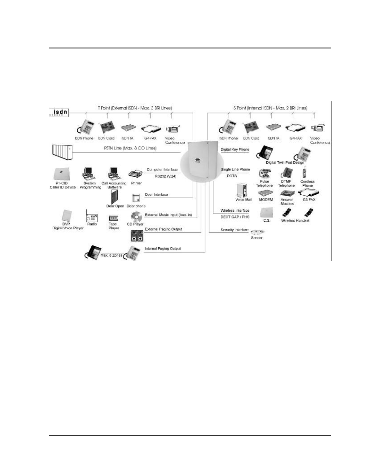
G1-824 - General Description
Description
The G1-824 is an advanced ISDN Digital hybrid telephone system employing a microprocessor stored program
and digitally controlled solid state Time-division switching. The G1-824 system is specifically designed for small
business as well as residential applications. At the forefront of the system design is a universal concept to
adapting and connecting with a variety of communications devices. Productive HYBREX Digital Key
Telephones offer thoughtfully designed productive feature access to keep you connected with one another and
customers. Auto Telecom technology leads the industry in providing for compatibility with devices such as fax
machines, answering machines, cordless phones, computer modems and other office/home equipment.
Key highlights of the G1-824 series include:
Economy and Efficiency
The base system is equipped to support two (2) or four (4) CO lines / two ISDN BRI’s and eight (8) digital
stations. The system may be expanded to a maximum of eight (8) CO lines / three (3) ISDN BRI’s. Station
cards may be selected to allow practically any combination ranging from all HYBREX DK1 Digital Sets to all
industry standard Single Line Telephone sets, with any combination of the two types. In addition to being cost
effective at the initial phase and for expanding to it's maximum capacity, the G1-824 system also is economical
to operate as it consumes about the same amount of electricity as a 60 watt light bulb at full configuration. A
maximum of 8 CO lines (or 3 ISDN BRI’s) and 24 Extensions can be accommodated. This allows a wide variety
of applications for the system to work effectively.
5
Page 20

Easy Installation
“Factory Ready” - All G1-824 Telephone systems are "ready to go" right out of the box. A well thought out
•
default database is factory installed on each system which meets the needs for most installations. This
alleviates hours of on site time, minimizing installation costs for both dealer and customer.
• “Small & Compact” - The Key Service Unit's small size takes little space for installation and is about the size
of a legal piece of paper.
Easy Maintenance
• Solid-state design minimizes trouble and eliminates periodic maintenance.
• Easy Expansion. Various Interface Cards for simple, modular expansion.
Versatile programming and options for ease of selection.
•
• Database Flash Memory Back Up - Customer data is backed up when the power is turned off and there is
no battery to replace.
• Battery Back Up (System Operation) - G1-824 systems can be equipped with an optional battery back up
which keeps the system operational for up to 1 hour in the case of a commercial power failure.
• Customer Care Programming - Customers and service personnel can easily communicate and perform
programming right over the telephone. HYBREX telephone systems allow programming and voice
conversations to be performed at the same time.
Advanced software upgrades – Through the RS232 connection, system software can be upgraded easily
•
without replacing any firmware.
Flexibility of System Applications
Unlike other conventional systems in the G1-824 size range, the installer will find an unprecedented range of
customer database programmability. In "system parameters" there are extensive options for various timing
settings related to features. An array of parameters are programmable for signalling options on outside lines
and internal single line telephone sets. The installer may Enable/Disable many system wide features. And in
class of service, there are over 20 options for each station providing maximum flexibility for nearly any
application.
Varied Extension Alternatives
You can connect an ISDN Modem, ISDN phone, proprietary HYBREX DK series Keyphone, Door Phone and
conventional industry standard single line sets – Modem, Answering Machine, Cordless phone, etc. directly to
the KSU. This feature provides you with the choice to select different extension equipment to suit individual
applications.
Digital Twin Port
Install two Digital Keyphones on a single two-wire cable. No Master and Slave difference. Any Keyphone can be
plugged in and plugged out with no interference to the other. This feature provides easy cabling, easy
expansion and easy maintenance.
Hybrid Phone
No waste of your existing telephone equipment, such as Modems, cordless telephones, Answer
machines,…etc., just plug this equipment into the “Hybrid port“ of the Keyphone and calls can be
automatically transferred to the equipment when you are busy or do not answer. No extra wiring and
programming. This feature provides easy installation and programming-free transfer of calls from the Keyphone
to SLT equipment.
6
Issue 1.5 / May, 2002
Page 21
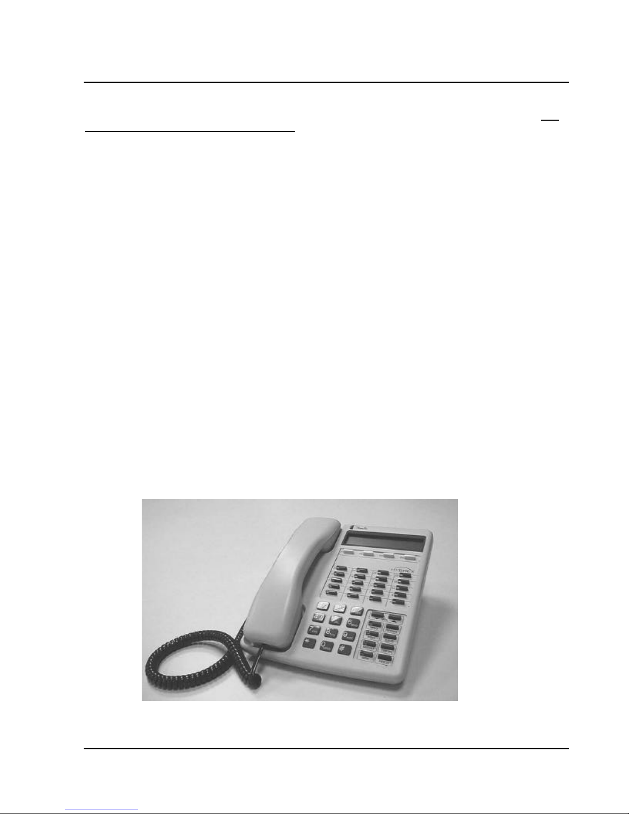
G1-824 - General Description
Full ISDN features
The G1 system allows you to access two different outside line types (PSTN & ISDN) in one box and enjoy Full
ISDN Features when accessing an ISDN Line - such as:
. Call Charge Metering Information
. Caller Identification
. Direct Inward Dialling
. Call Forward Internal / External
. Call Waiting
. MSN (Multiple Subscriber Number)
. Sub-addressing
. User to User Signalling
You can easily control your budget by using different outside line arrangements.
Liquid Crystal Display
The DK1 Series Telephone Model DK1-21 / DK1-31 is equipped with a large, easy to read LCD display. The
LCD is 32 characters total, comprised of 2 rows by 16 characters each. This LCD provides an invaluable tool
for simplifying the use of the telephone by identifying the calling extension by name, outside lines by name and
self prompting displays for feature access. Station feature usage is made simple with the help of the LCD
display. Continuous prompting information is displayed during calls so that users know what to do and when to
do it.
32-character LCD Display shows:
• Time • Last number dialled
• Dialled telephone number • The status of operation/function
• Voice Mail Messages • Absent messages
• CO Line Names • Speed Dial Directory
Last Number Redial
•
• Speed dial number • Input data during system data entry
Calling Party Number and Name
•
HYBREX Telephone Model DK1-21/DK1-21H/DK1-31
7
Page 22
Specifications
MAXIMUM LOOP RESISTANCE/IMPEDANCE
Key Telephone Less than 40 ohms 26 AWG / 200 m
Single Line telephone Less than 800 ohms 26 AWG / 800 m
DoorPhone Less than 40 ohms
Music Source Input Impedance 600 ohms
Maximum Input 0.775 VRMS
INTERNAL RELAY CONTACTS
Type SPST
Rating 1 AMP, 24VDC
Function Door Switch, Music on Hold, etc
CABLE REQUIREMENTS
CO/PABX Line Twisted 1 Pair (2 wires)
ISDN BRI Twisted 2 Pair (4 wires)
DK1 Digital Key Telephone Twisted 1 Pair (2 wires)
DoorPhone Twisted 1 Pair (2 wires)
Door Switch Twisted 1 Pair (2 wires)
External Sensor Twisted 1 Pair (2 wires)
External Music Source Twisted 1 Pair (2 wires)
Single Line Telephone Twisted 1 Pair (2 wires)
Mechanical Specifications (Key Service Unit)
CABINET DIMENSIONS
233mm W 76mm D 290mm H
9.17” 2.99" 11.4"
WEIGHT 2.3 Kg (Configuration: 4 x 8)
5.0 lbs
Mechanical Specifications (Battery Back Up Housing)
CABINET DIMENSIONS
15.5” W 3.0” D 5.75” H
WEIGHT With Batteries -16 lbs Without Batteries- 4 lbs.
Mounting Screws 12.25” centre to centre
Environmental Specifications
OPERATING CONDITIONS STORAGE
Temperature 0º to 45º C -40º to 66º C
(32º to 113º F) (-40º to 150º F)
Humidity 10 to 95% relative 10 to 95% relative
Non-condensing non-condensing
CONDITIONS
8
Issue 1.5 / May, 2002
Page 23

Features
System Features
Account Code Capability
Attendant Console Assignment
Attendant Overflow
Automatic Line Access
Automatic Line Search
Automatic Ringdown
Automatic Wake-up
Battery Charger
Behind PABX Operation
Centrex Operation
Class Of Service
CO Line Groups
CO Line Hunting
CO Line Name Programming
CO Line Ring Types
Linear
Common Audible
Circular
Hunt
Console Assignment
Day/Night Service
Manual/Automatic Switch
Dial 9 Group
Direct In Line
Dial By Name
Dial Mode Selection(DP/DTMF)
Dial Pulse to DTMF Conversion
Distinctive Ringing
DTMF Signalling
Dual Port Capability
End to End Signalling
Easy Installation and Operation
Flash (Programmable)
Flash Memory Backup Memory
Flexible Expansion
Flexible Ringing Assignment
Flexible Key Group Assignment
Flexible Number Plan 2,3 or 4 Digit
Flexible Time Format 12/24 Hour
Forced Account Code Assignment
Intercom
Intercom Single Digit Assignment
Intercom Ring / Voice Select
Intercom Dialling Restriction
G1-824 - General Description
ISDN
Call Charge Metering Information
Caller Identification
Direct Inward Dialling
Call Forward Internal / External
Call Waiting
MSN (Multiple Subscriber Number)
Sub-addressing
User to User Signalling
Host PABX Access
Hot line
Line Group Assignment
Loud Bell Assignment
Multiple Attendant Consoles
Multiple Trunk Groups
Night Transfer
On Call Programming
Paging
Internal
Zone
Meet Me
Password Assignment
DISA
System programming
Toll Override
Pause
Pick Up Groups
Power Fail Transfer
Security Code
Single Digit Dialling
Station Group Assignment
Station Hunting
Station Lock
System Speed Dial and Personal Speed Dial
System Date & Time Setting
System Time-Reminder Service
Telephone Directory
Toll Control
Day / Night
Tone to pulse dialling
Trunk Queuing
Trunk to trunk connections
Uniform Call Distribution
Voice Mail Compatibility
9
Page 24

Page 25

Station Features
Advisory Messages
System
Personal
Access to System Programming
Account Code Capability
Auto Hold
Auto Hold Recall
Automatic Call Back
Automatic Answer-Intercom
Automatic Line Access
Automatic Redial
Automatic Volume Increase
Brokers Call
Call Duration Timer (LCD Phones)
Call Waiting
Call Forwarding
All Calls
Busy
No Answer
Busy / No Answer
External
Call Pickup
Call Split
Call Transfer
Calling Name Display (LCD Phones)
Calling Number Display (LCD Phones)
Camp On
Chain Dialling
Conference
Dial By Name (LCD Phones)
Dial Access to Attendant
Direct Station Selection
DoorPhone Access
Do Not Disturb (DND)
Dual Color LED
Duration Time Display (LCD Phones)
Executive Override (Barge-In)
External Call Forwarding
Flash (Open Loop Timed Flash)
Hands-free Answer Back
Hearing Aid Compatibility
Headset Compatibility
Hold (Exclusive / System)
Hold Recall
I Hold Indication
I Use Indication
Intercom
Intercom ring / voice interchange
Intercom Step Call
Intercom Voice Announce
Last Number Redial
Message Waiting
Multi-Language Display
On Hook Dialling
G1-824 - General Description
11
Page 26
Parts & Peripherals
System Modules
Model
G1-408P KSU with 4 CO lines, 4 Digital twin ports
G1-408i KSU with 2 ISDN S/T , 4 Digital twin ports
G1-608i KSU with 3 ISDN S/T , 4 Digital twin ports
G1-TKU-4 Trunk Card : 4 CO lines
G1-TKU1-4 Trunk Card : 4 CO lines / with CLIP (Caller ID) upgrade option
G1-SIU-2 ISDN S/T interface with 2 circuits
G1-SIU-3 ISDN S/T interface with 3 circuits
G1-STC-8 Station Card : 4 Digital Twin-port
G1-SLC1-8 Single Line Card : 8 SLT ports / with CLIP (Caller ID) function
G1-RGU1 Ring Generator Unit for G1-SLC1-8
G1-SLC-8 Single Line Card : 8 SLT ports
G1-RGU Ring Generator Unit for G1-SLC-8
Type of Phones
Model Description
DK1-21H Multifunction Key Telephone. Includes 32 character LCD display, single line
DK1-21 Multifunction Key Telephone. Includes 32 character LCD display, speakerphone,
DK1-22 Multifunction Key Telephone. Includes speakerphone, Handsfree, headset jack, 20
DK1-31 Multifunction Key Telephone. Includes 32 character LCD display, intercom
DK1-33 Multifunction Key Telephone. Includes intercom speakerphone, 8 dual color keys and
DK1-SLC DK1 Keyphone - SLT port for DK1-2x series
DK-SLD Two Port SLT device – Convert a Digital port to two POTS ports
ACP Access Control Phone
ACP/RF Access Control Phone with RF Proximity Card function
PX-Card RF Proximity Card for ACP/RF
WMU-12 Wall Mount Kit for DK1 Series Telephones
Description
telephone port, speakerphone, Handsfree, headset jack, 20 dual color keys and 14
function keys for feature access, DSS, CO Lines and speed dial.
Handsfree, headset jack, 20 dual color keys and 14 function keys for feature access,
DSS, CO Lines and speed dial.
dual color keys and 14 function keys for feature access, DSS, CO Lines and speed
dial.
speakerphone, 20 dual color keys and 14 function keys for feature access, DSS, CO
Lines and speed dial.
14 function keys for feature access, DSS, CO Lines and speed dial.
Peripheral Devices
Model Description
DPU05 Door Phone - 2 Wires
BBOX0 Battery Box without Batteries
BBOX1 Battery Box with Batteries
Optional Interface Cards
Model Description
G1-VSC Voice Service Card (60 sec. / 8 voice segments)- Auto Attendant, Wake-up, Message
G1-MSC RS232/Relay/Sensor/External Paging Interface
G1-CIC Caller ID Card for G1-TKU1-4 – Dual Mode (FSK/DTMF)
G1-CIC-F Caller ID Card for G1-TKU1-4 – FSK Mode
G1-CFC Conference – 32 parties conference
12
Issue 1.5 / May, 2002
Waiting
Expansion Card – Expand system from 6 x 16 to 8 x 24
Page 27
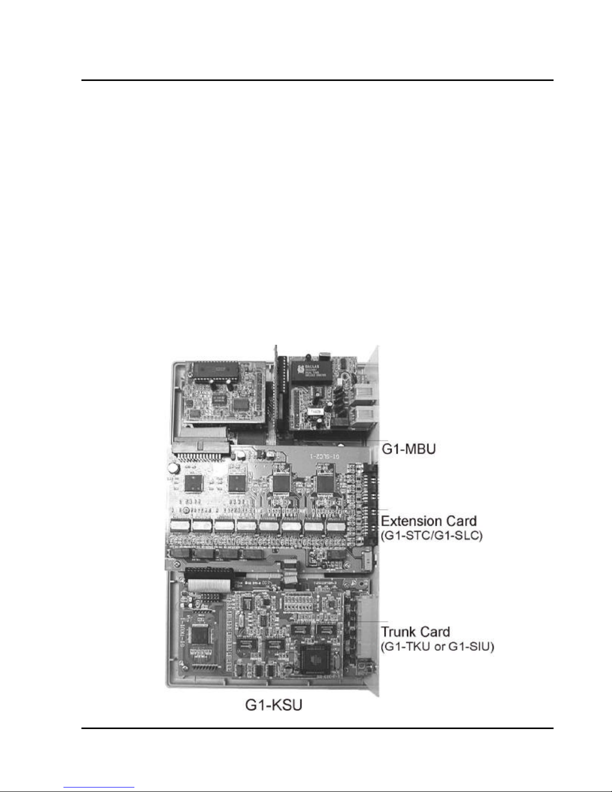
System Installation - Introduction
This section provides directions for installing the system and optional equipment.
The installation must be performed by qualified service personnel.
Main components of the system are:
GDS-600 - General Description
Key Service Unit, which includes:
Power Supply Unit (G1-PWU)
•
Main Board Unit (G1-MBU / Common Control
•
and four digital twin port circuits)
Trunk Unit (G1-TKU / G1-SIU)
•
Optional Expansion Cards:
Trunk Card (G1-TKU / G1-SIU)
•
Digital Station Card (G1-STC – four digital twin
•
port circuits)
Single Line Station Card (G1-SLC – eight single
•
line port circuits)
• G1-CIC Card (Caller ID Card - four port circuits)
Conference Card (G1-CFC)
•
Multi-Service Card (G1-MSC)
•
Voice Service Card (G1-VSC)
•
NOTE: Please follow the directions step by step. The G1-824 system should be installed in strict accordance
with this manual.
13
Page 28
Site Requirements
Location
Choosing the Right Environment
• System should be installed in a clean, dry, secure location. This location must have adequate ventilation,
and a temperature from 0 to 45 (32 to 113), with 10% to 95% non-condensing relative humidity.
DO NOT install the equipment near sources of static electricity, excessive vibration, or water. Avoid direct
sunlight.
Installation Checklist
INSTALLATION REQUIREMENTS VERIFICATION
MOUNTING SURFACE Flat surface with adequate space for main cabinet,
power supply, wiring and optional Battery Backup
cabinet.
AC LINE AC line should be dedicated exclusively to the system.
POWER OUTLET Power Outlet must be a
3-wire grounded outlet plug, having parallel blades
and ground pin.
Input power Line capacity requirements - 10 amperes.
SURGE PROTECTION A Surge Protector is recommended on the dedicated
AC line.
VENTILATION AND TEMPERATURE Humidity: 10% to 95% relative non-condensing
Temperature:32 to 113 (0 to 45 ).
EARTH GROUND A proper ground connection. (14 AWG)
SERVICEABILITY Lighting conditions and working space adequate for
future service.
Equipment Requirements
Unpack, Check and Verify Equipment - Unpack the telephone equipment boxes and verify the contents in
•
accordance with the packing list provided. If any discrepancies are noticed, please contact Auto Telecom or
Authorized Dealers.
• Damaged Boxes - If you notice any damage to the packages, please notify both the shipper and Auto
Telecom or Authorized Dealers at once.
• List of parts included in basic KSU box:
• KSU Main Cabinet
Power Supply
•
Mounting Template
•
Mounting Screws
•
Station Quick Connectors
•
• Spare Fuses
• Cable Cover
14
Issue 1.5 / May, 2002
Page 29

GDS-600 - General Description
Installation
Caution 1. This system should be installed by qualified service personnel.
2. Do not install the Power Supply unless you have read the following instructions
and completed all the installation and wiring.
3. STATIC SENSITIVE DEVICES! Please handle with care.
Installing expansion and optional cards
In this step you will be installing printed circuit cards on to header pins of the main board in the basic cabinet.
Take your time and extra care to assure the printed circuit cards are properly aligned. After installing each
option and expansion card, perform a visual inspection to assure the printed circuit card is installed properly.
1. Position the cabinet on a flat surface like a table or countertop. Avoid doing this on carpet.
2. Remove the 4 screws located at the corners of the cabinet and lift the front cover off.
3. Locate the expansion and option cards and unpack them at this time.
15
Page 30
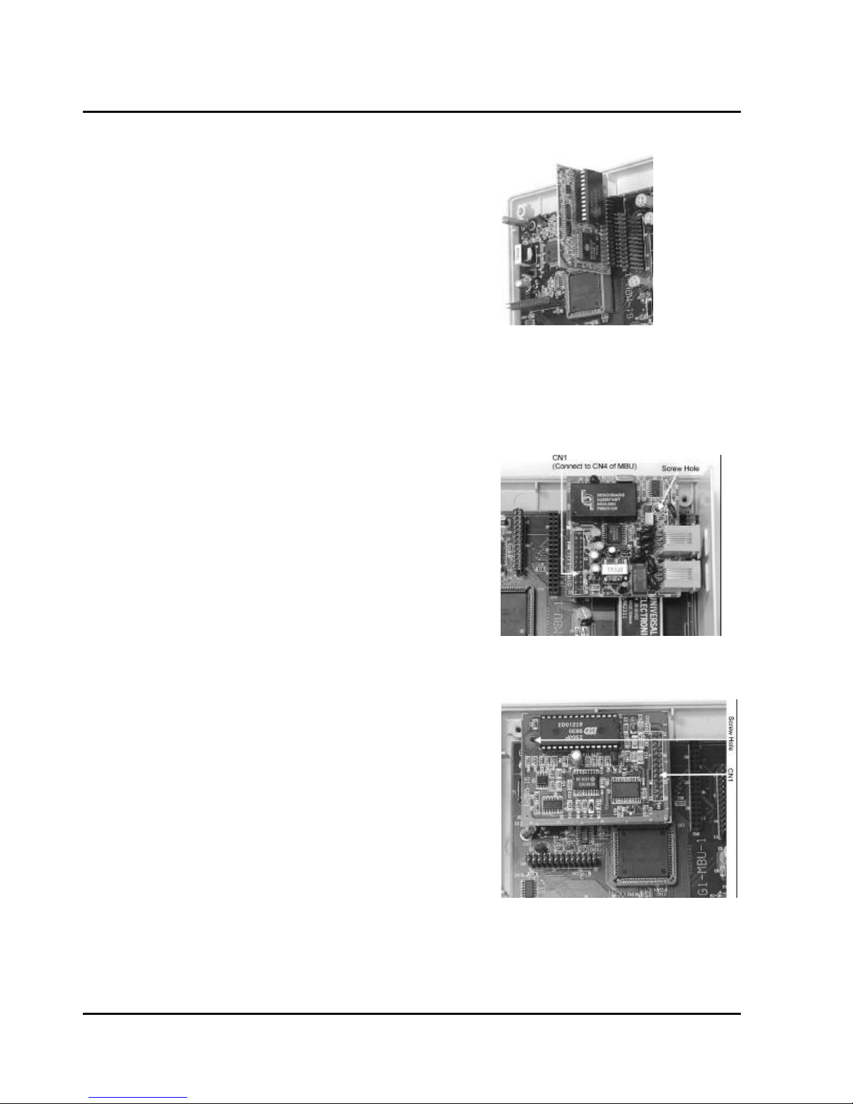
Installing expansion and option cards (continued)
G1-CFC- Conference Card
Install this card on CN6 of the G1-MBU.
l
Be sure that the component side of the G1-CFC is facing in
l
towards right of KSU.
CFC card is necessary for expanding system from 6 x16 to 8x
l
24.
G1-MSC- Multi Service Card
Align CN1 of the MSC card with CN4 of the G1-MBU.
l
Align the hole on the right side of the MSC with the standoff.
l
Once aligned push the MSC on the connector.
l
Place the screw into the standoff securing the MSC card.
l
When installed correctly the connectors should be easily
l
accessible through the main panel.
G1-VSC- Voice Service Card
Align CN1 of the G1-VSC card with CN5 of the G1-MBU.
l
Align the hole on the left side of the VSC with the standoff.
l
Once aligned push the VSC on the connector.
l
Place the screw into the standoff securing the VSC card.
l
16
Issue 1.5 / May, 2002
Page 31
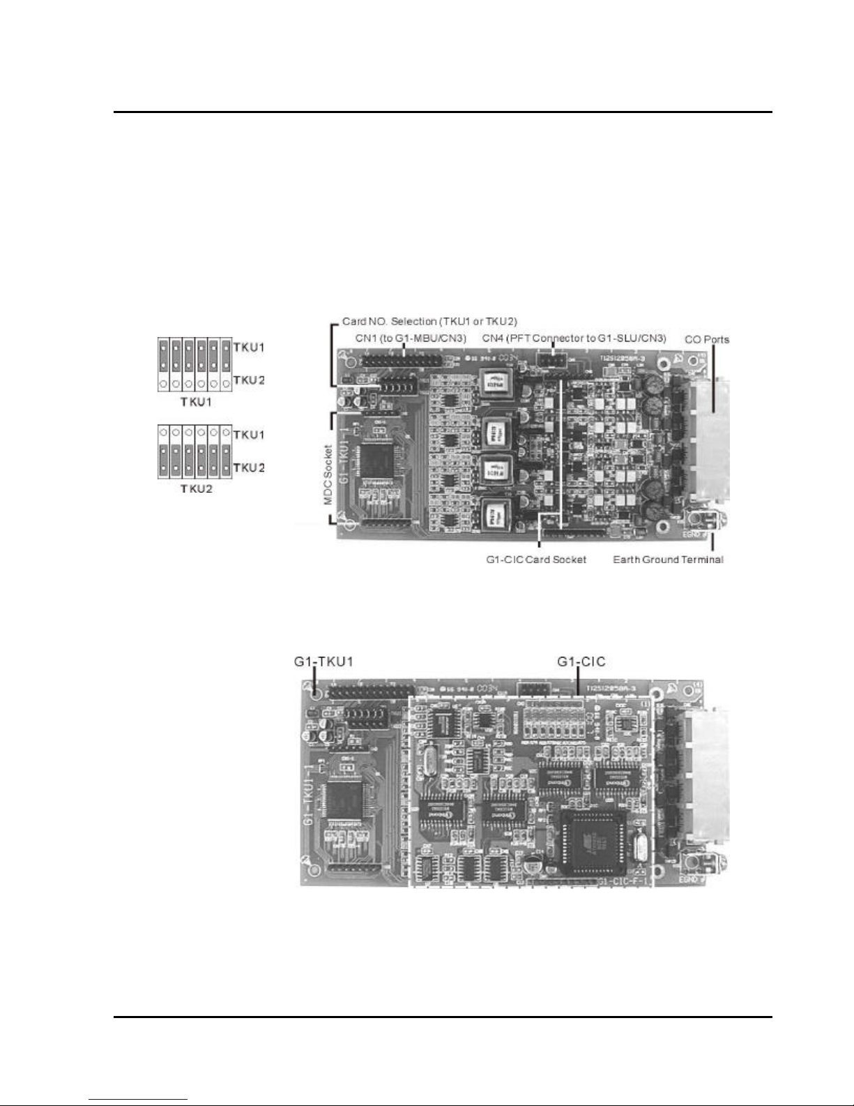
GDS-600 - General Description
G1-TKU- 4 Port CO Line Card
Align four holes of G1-TKU with the standoffs on top of the existing G1-TKU or G1-SIU card provided for in
l
the basic key service unit. Once aligned, place the four screws into the standoff securing the G1-TKU card.
Set SW1 on the newly installed G1-TKU to ‘TKU1’ position if the basic key service unit was installed with a
l
G1-SIU card already.
Set SW1 on the newly installed G1-TKU to ‘TKU2’ position if the basic key service unit was installed with a
l
G1-TKU card already.
Connect an attached cable between CN1 of G1-TKU to CN3 of G1-MBU.
l
Connect an attached cable between CN4 of G1-TKU to CN3 of G1-SLC for power failure transfer.
l
G1-CIC- Caller ID Card
Align pin connectors of G1-CIC card with the related socket on G1-TKU1 card and then push down G1-CIC
l
on G1-TKU1 Card.
17
Page 32
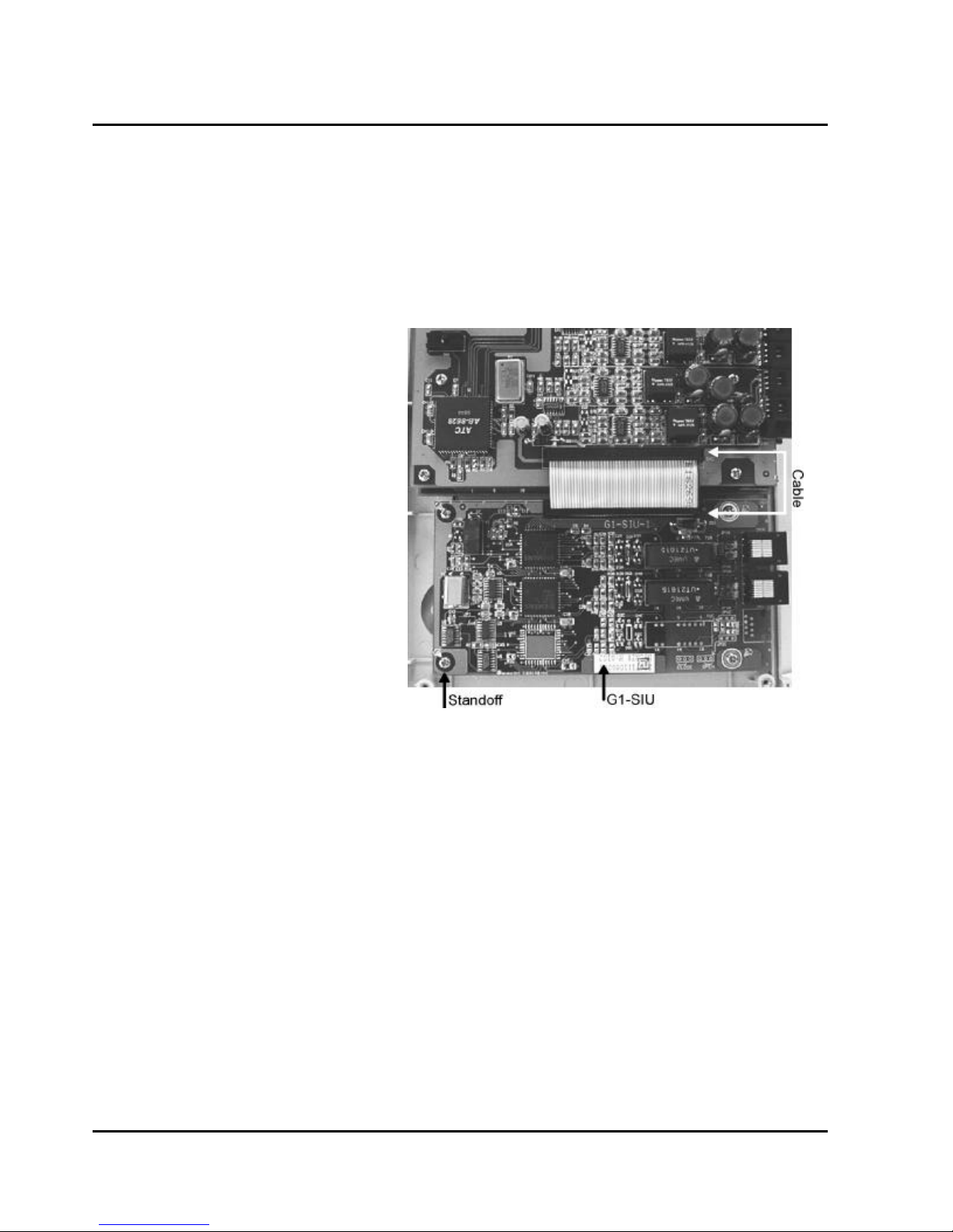
G1-SIU ISDN S/T Interface Card
If the ISDN interface – G1-SIU is to be installed in the original basic key service unit (G1-408P), the
l
existing G1-TKU needs to be uninstalled first.
Replace the PVC plate with the attached one on the main panel.
l
Align four holes of G1-SIU with the screw holes on the plastic cabinet, place the four standoffs into the
l
holes securing the G1-SIU card.
Connect an attached cable between CN2 of G1-SIU to CN2 of G1-MBU (or to CN2 of G1-STC.)
l
Install G1-TKU on the top of G1-SIU.
l
18
Issue 1.5 / May, 2002
Page 33
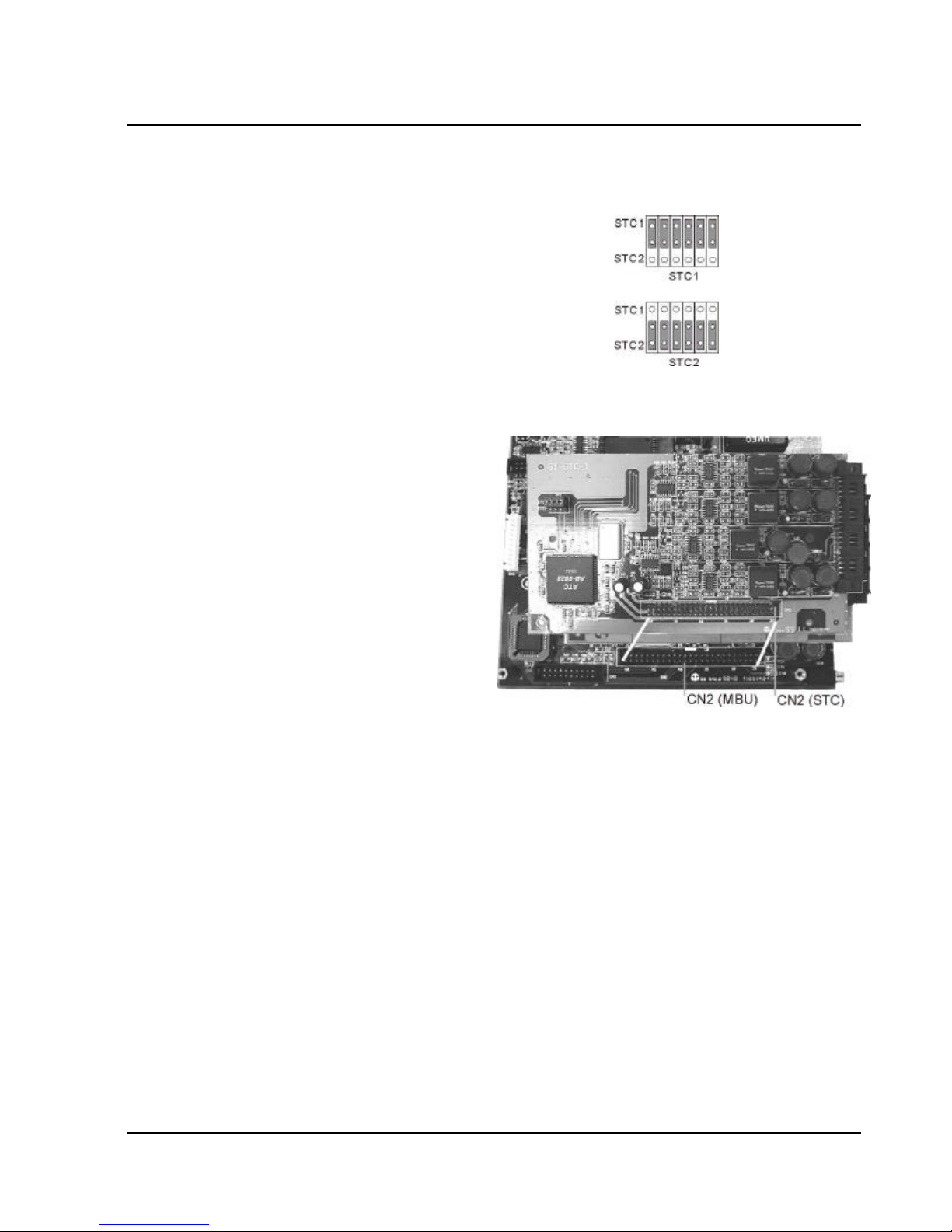
G1-STC Digital Station Adapter Card
For the 1st G1-STC card:
Set SW2 on G1-STC to ‘STC1’ position.
l
Align CN2 of the G1-STC card with CN2 of the G1-MBU.
l
Align four screw holes on G1-STC with the standoff.
l
Once aligned push the G1-STC on the connector.
l
Place the screw into the standoff securing the G1-STC card.
l
For the 2nd G1-STC card:
Install G1-CFC card.
l
Use the attached three standoffs to replace the
l
original screws on the 1st G1-STC card.
Set SW2 on the 2nd G1-STC to ‘STC2’ position.
l
Align CN2 of the two G1-STC cards together.
l
Align four screw holes on G1-STC with the
l
standoffs.
Once aligned push the G1-STC on the
l
connector.
Place the screws into the standoffs securing the
l
G1-STC card.
GDS-600 - General Description
19
Page 34
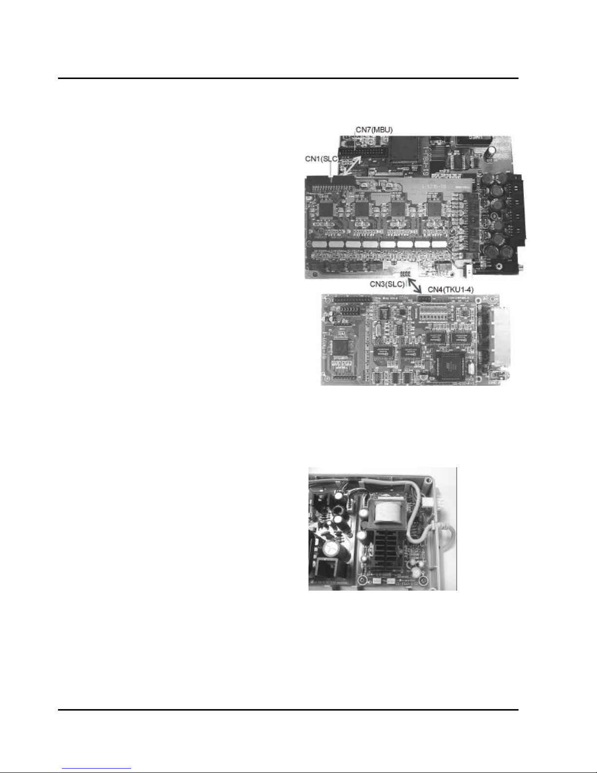
G1-SLC Single Line Station Adapter Card
Install G1-SLC on G1-MBU:
Connect the attached cable between CN1 of G1-SLC
l
card to CN7 of the G1-MBU.
Align four screw holes on the G1-SLC with the
l
standoffs.
Place the screws into the standoffs securing the G1-
l
SLC card.
Connect the attached cable between CN3 of G1-
l
SLC to CN4 of G1-TKU for power fail transfer.
(Power fail Transfer will transfer the CO lines to the
first 4 stations of G1-SLC card.)
Install G1-SLC on the top of G1-STC:
Install G1-CFC card.
l
Use the attached three standoffs to replace the
l
original screws on the 1st G1-STC card.
Connect the attached cable between CN1 of G1-SLC
l
card to CN7 of the G1-MBU.
Align four screw holes on the G1-SLC with the
l
standoffs.
Place the screws into the standoffs securing the G1-
l
SLC card.
Connect the attached cable between CN3 of G1-SLC
l
to CN4 of G1-TKU for power fail transfer. (Power fail
Transfer will transfer the CO lines to the first 4 stations of G1-SLC card.)
G1-RGU - Ring Generator Unit (for G1-SLC)
The ring generator installs inside the power supply
l
unit.
Remove the cover of the power supply by taking out
l
the 4 screws located on each corner.
Inside the G1-RGU are 4 screws and a connecting
l
cable.
Align the G1-RGU with the 4 holes and secure by
l
installing the screws provided.
Install the cable from the G1-RGU to the 4 pin header
l
connector located on the G1-PWU board.
20
Issue 1.5 / May, 2002
Page 35
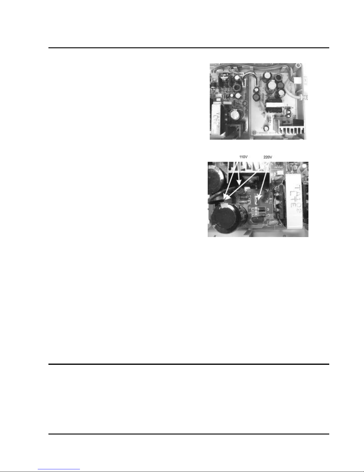
GDS-600 - General Description
G1-RGU1 - Ring Generator Unit (for G1-SLC1 (CLIP
version))
The ring generator installs inside the power supply unit.
l
Remove the cover of the power supply by taking out the
l
4 screws located on each corner.
Inside the G1-RGU1 are 4 screws and a connecting
l
cable.
Align the G1-RGU1 with the 4 holes and secure by
l
installing the screws provided.
Install the cable from the G1-RGU1 to the 4 pin header
l
connector located on the G1-PWU board.
Voltage Selection Check
Make a check to assure the power supply jumper setting
l
is for the proper voltage.
When complete, place the power supply cover back on
l
the power supply.
Replace Cover
With the expansion and option cards installed and the battery insulator removed, replace the cover and install
the 4 screws removed earlier.
This concludes the installation of expansion and option cards!
21
Page 36
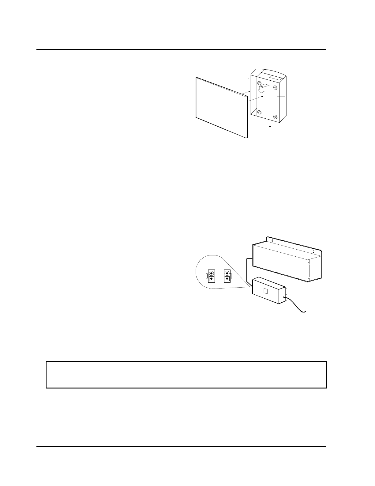
Installing the Equipment
Backboard
Be sure to plan and allow enough space to mount and
connect the key service unit, power supply and system
battery back up if applicable.
Mounting Tabs
Key Service Unit
Use the enclosed paper template to locate the mounting
position for the Key Service Unit. Drill appropriately
spaced holes and mount the KSU on the wall. When
Wall or backboard
Key Service Unit
mounting the KSU, make certain that there is adequate
room for the system power supply and that the connecting cable between the Power Supply and the KSU will
reach the KSU. The same applies for the battery back up unit.
Power Supply
Dedicated Power Source - The power supply must be connected to a dedicated AC outlet.
Be sure that the third wire earth ground of the AC circuit is connected to a good electrical ground. If a music
source is installed, it must be connected to a separate AC circuit rather than the system's dedicated AC line
cord.
Check Your Voltage Selection Jumper
Verify that the input voltage and input voltage jumper are correct before you power on the system. The input
voltage is set according to the Customer's requirement before shipping. However it is important to verify that
the setting is correct prior to initial system power up.
Power Supply voltage options for the unit:
100-VAC: 100 to 120 V AC (50/60Hz) or 240-VAC:
205 to 265 V AC (50/60Hz).
Mount Power Supply
Using screws provided with the system, mount the
power supply close to the KSU so that the connector
reaches from the Power Supply to the KSU.
Preparing The External Battery Backup
The Key Service Unit can have two external backup
batteries in series (12 volts each) for emergency
power when a power failure takes place.
If you are installing an optional Battery Backup (BBOX1), make certain that there is adequate room for its
installation. Make certain that the Battery Backup is mounted close enough to the Power Supply that the
interconnecting cable between the Battery Backup and the Power Supply can connect.
Do Not Connect the Battery Backup at this time!
Do Not Connect the Battery Backup at this time! Battery Backup should not be
connected to the System power supply until all power up testing has been
completed!
22
Issue 1.5 / May, 2002
Page 37
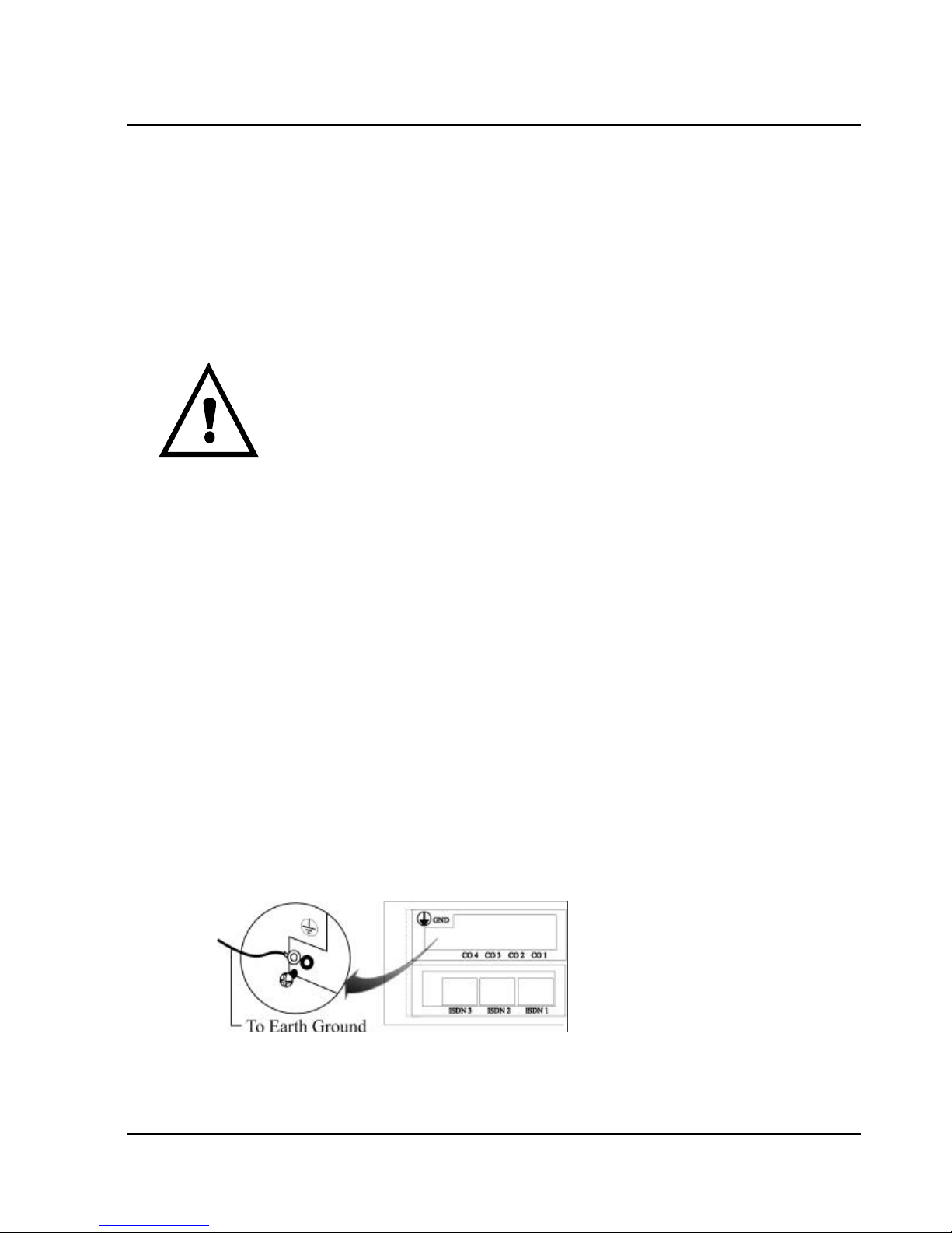
GDS-600 - General Description
Charging the Battery
The rechargeable batteries are automatically charged when the KSU is plugged in.
When System is in a full-load condition (eight CO Trunks and twenty-four Extensions all in use), the batteries
provide a minimum of 1 hour's consecutive use. Change the batteries every two years.
Installing or Replacing Batteries
Caution
To Reduce the Risk of Fire or Injury to persons, Read and Follow these Instructions.
1. Use only the following type and size batteries:
12 Volt 6.5 Amp/Hour "Gel-Cell" sealed batteries (2).
Dimensions, approximately 3 1/4" (H), 5 15/16" (W), 2 1/2" (D).
PowerSonic model PS660 or equivalent.
2. Do not dispose of the batteries in a fire. The cell may explode.
Check with local codes for possible special disposal instructions.
3. Do not open or mutilate the batteries. Released electrolyte is corrosive and may
cause damage to the eyes or skin. It may be toxic if swallowed.
4. Exercise care in handling batteries in order not to short the battery with
conducting materials such as rings, bracelets, and keys. The battery or conductor may overheat and cause
burns.
This product is defined as a secondary battery operated device. As such, the following instructions
should also be read and followed:
1. Charge the batteries provided with or identified for use with this product only in accordance with the
instructions and limitations specified in this manual.
2. Observe proper polarity orientation between the batteries and battery charger.
3. Do not mix old and new batteries in this product.
4. Do not mix batteries of different sizes or from different manufacturers in this product.
Before installing or replacing batteries, disconnect the battery supply unit to the KSU by removing the polarized
battery connector at the KSU. Due to the weight of the batteries, it is advised that the battery cabinet be
removed from the wall before working on it.
System Ground
It is strongly recommended that the system be grounded by connecting a heavy, insulated copper wire (e.g.,
14AWG or larger) between the grounding bolt on the right-lower side of the cabinet and an earth ground.
Without this System Ground there is no protection against lightning damage to Co lines and warranty will be
voided.
Do not connect the grounding wire of the KSU to a computer, telex, or any other external device.
KSU Connecting (Main) Panel Layout
23
Page 38
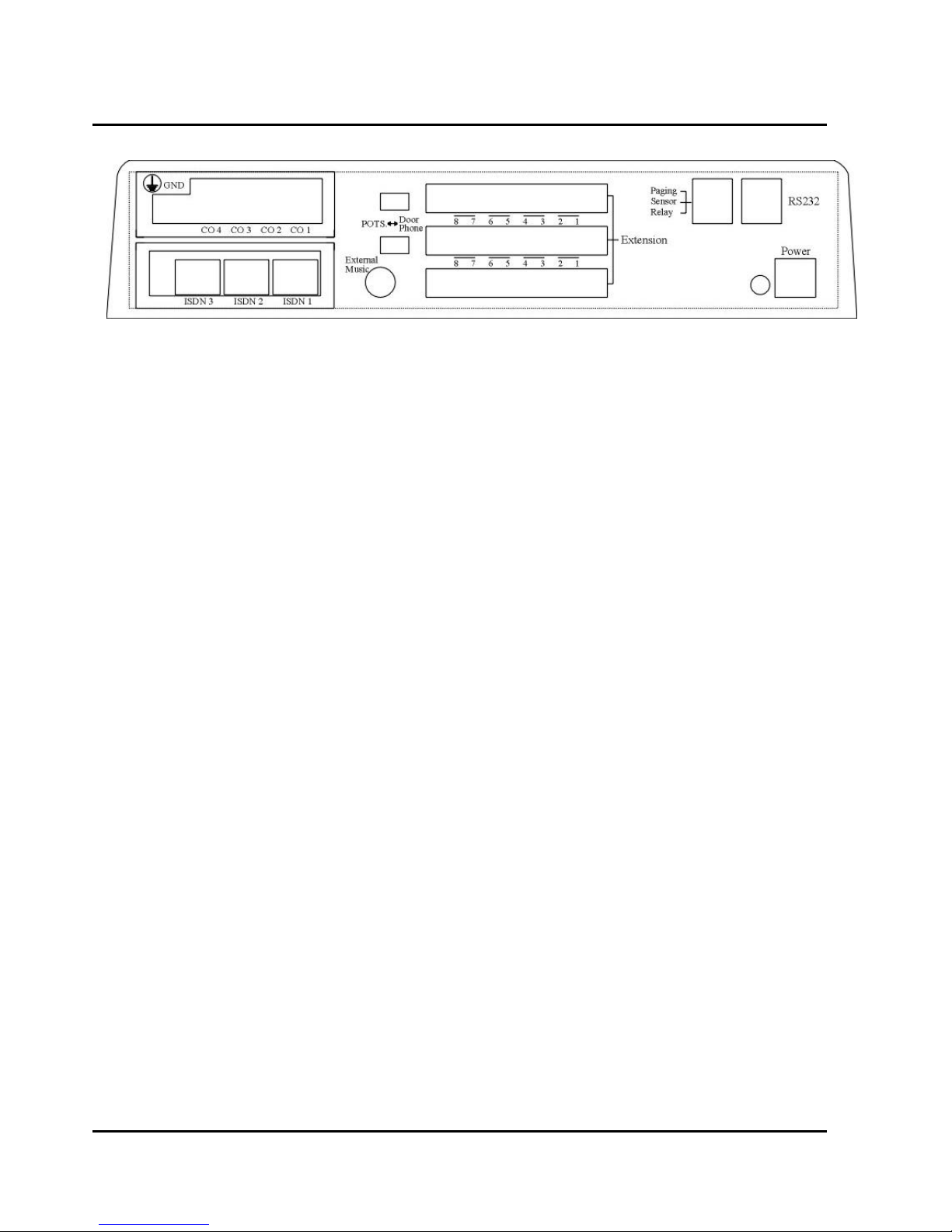
G1-824 KSU Main Panel
The following illustration should be used as a reference when connecting equipment to the G1-824 KSU.
Refer to the wiring diagram located on the inside of the cable cover for all connections
Connecting Stations
The station cabling for the G1-824 should be a home run from the jack to the telephone room. The termination
should be at conventional 66 type connecting blocks or Krone blocks or directly to the provided station
connectors. One pair twisted wiring is required for each station location. Attention to proper cabling will go a
long way towards a successful installation and minimizing service calls after installation. Some guidelines for
running station cable are as follows:
Avoid running cable parallel to fluorescent light fixtures or electrical lines not in conduit. If these obstacles
l
are unavoidable, run the cable at right angles across them.
Do not run station cable inside conduit already occupied by electrical wiring.
l
Do not run station cable near equipment with electric motors or strong magnetic fields.
l
Do not place station cable on the ground where it can be stepped on or rolled over by office furniture or
l
office equipment.
24
Issue 1.5 / May, 2002
Page 39
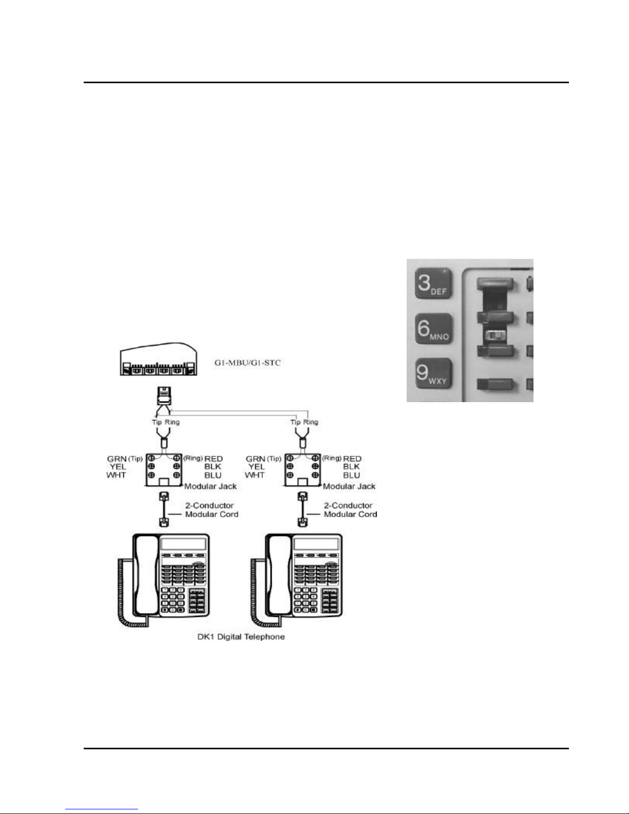
GDS-600 - General Description
Digital Key Telephone – DK1-21/22/31/33
A cable cover is provided with the KSU. Station cables can enter from either the top or bottom as desired.
l
Remove one or both ends of the cover as required and route the station cable through the hole. Terminate
the station wires with the connectors that are provided. The stations will connect to the KSU as shown on
the main panel (above) on connector locations 11 – 28.
Connect Tip terminal with GRN terminal (screws) of the modular jack, Ring with RED.
l
There is no polarity requirement on Tip and Ring.
l
2-conductor wiring is required for DK1 Digital Key Telephones.
l
Open the overlay of the function key on DK1 telephone and select the 1st or 2nd station. Dip switch to the
l
right for the 1st station. Dip switch to the left for the 2nd station.
Take care that if you are paralleling 2 DK phones on a Digital Twin Port that neither of the DK phones
l
contains a DK1-SLC card. The presence of thee DK1-SLC card will prevent the correct operation of the
Digital Twin Port. Any DK phone containing a DK1-SLC must be connected to its own individual Digital
Twin Port.
Dip to right: the 1st station.
Dip to left: the 2nd station.
Station Connection
CAUTION!: Avoid shorting Tip and Ring together. It may damage the G1-MBU or G1-STC board.
25
Page 40
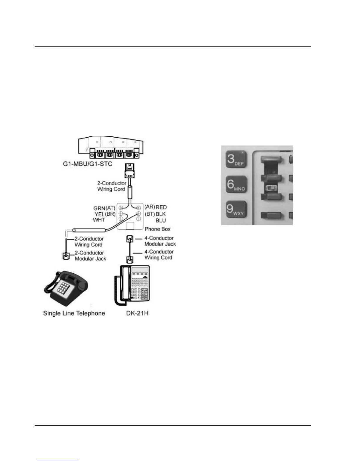
Digital Key Telephone – DK1-21H
A cable cover is provided with the KSU. Station cables can enter from either the top or bottom as desired.
l
Remove one or both ends of the cover as required and route the station cable through the hole. Terminate
the station wires with the connectors that are provided. The stations will connect to the KSU as shown on
the main panel (above) on connector locations 11 – 28.
Connect Tip terminal with GRN terminal (screws) of the modular jack, Ring with RED.
l
There is no polarity requirement on Tip and Ring.
l
4-conductor wiring is required for DK1-21H Digital Key Telephones from the Handset to Wall socket.
l
Open the overlay of the function key on DK1-21H telephone and select the 1st station.
l
Connect the single line telephone from the phone box. Connect Tip terminal with YEL terminal (screws) of
l
the modular jack, Ring with BLK..
Dip to right on DK1-21H
CAUTION!
1. Avoid shorting Tip and Ring together. It may damage the G1-MBU or G1-STC board.
2. System does not allow another Digital key phone to be connected on the same digital twin port as a
DK1-21H.
26
Issue 1.5 / May, 2002
Page 41
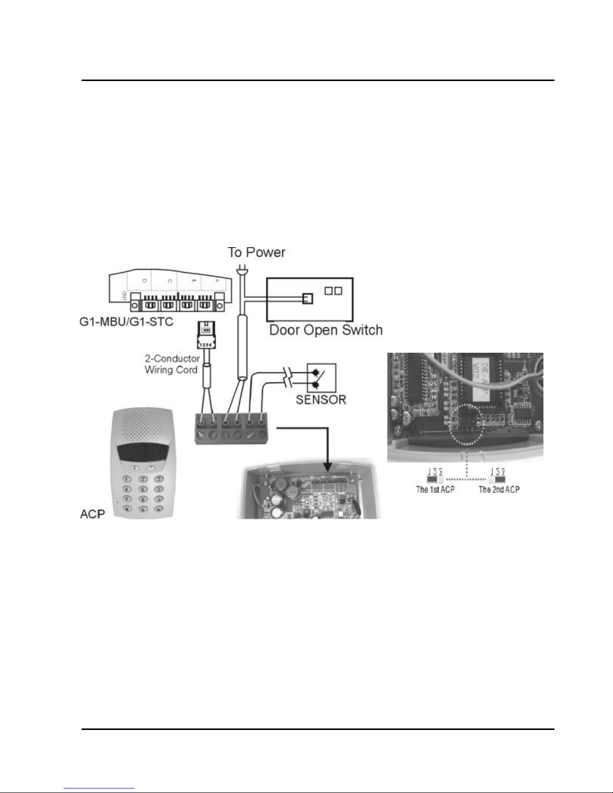
GDS-600 - General Description
Access Control Telephone – ACP
A cable cover is provided with the KSU. Station cables can enter from either the top or bottom as desired.
l
Remove one or both ends of the cover as required and route the station cable through the hole. Terminate
the station wires with the connectors that are provided. The stations will connect to the KSU as shown on
the main panel (above) on connector locations 11 – 28.
Connect Tip/Ring terminals from KSU(G1-MBU/G1-STC) to the ACP connector (6 contacts).
l
There is no polarity requirement on Tip and Ring.
l
Connect Relay for applications such as door open to the ACP connector (6 contacts).
l
Connect Sensor for applications such as door open alarm to the ACP connector (6 contacts).
l
Mount ACP connector on to ACP itself.
l
Select the 1st or 2nd station. Jumper as shown in diagram below.
l
Mount ACP on the wall.
l
CAUTION!: Avoid shorting Tip and Ring together. It may damage the G1-MBU or G1-STC board.
27
Page 42
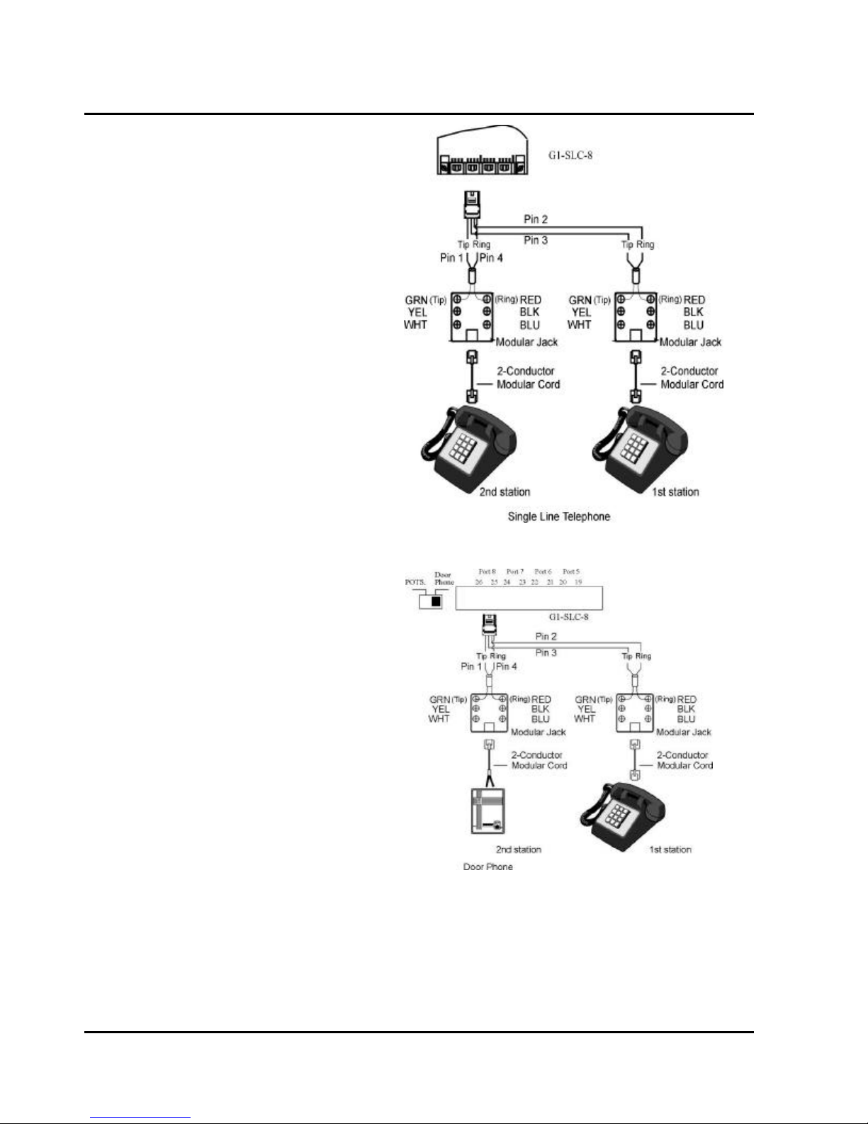
Single Line Telephone (connected to G1-SLC)
A cable cover is provided with the KSU.
l
Station cables can enter from either the top or
bottom as desired. Remove one or both ends
of the cover as required and route the station
cable through the hole. Terminate the station
wires with the connectors that are provided.
The stations will connect to the KSU as shown
on the main panel (above) on connector
locations 27 – 34 (Needs G1-SLC installed).
Connect Tip terminal with GRN terminal
l
(screws) of the modular jack, Ring with RED.
There is no polarity requirement on Tip and
l
Ring.
2-conductor wiring is required for Single Line
l
Telephones.
Door Phone Connection
One Door phone may be connected to the G1-
l
824 system.
A cable cover is provided with the KSU. Door
l
phone cable can enter from either the top or
bottom as desired. Remove one or both ends
of the cover as required and route the door
phone cable through the hole. Terminate the
door phone wires with the connectors that are
provided. The Door phone will connect to the
KSU as shown on the main panel (above) on
connector locations 34 (Needs G1-SLC
installed).
Connect Tip terminal with GRN terminal
l
(screws) of the modular jack, Ring with RED.
No polarity on Tip and Ring.
l
2-conductor wiring is required for Door phone.
l
Adjust the DIP selector on the main panel to
l
Door Phone.
Door Phone Connection
28
Issue 1.5 / May, 2002
Page 43
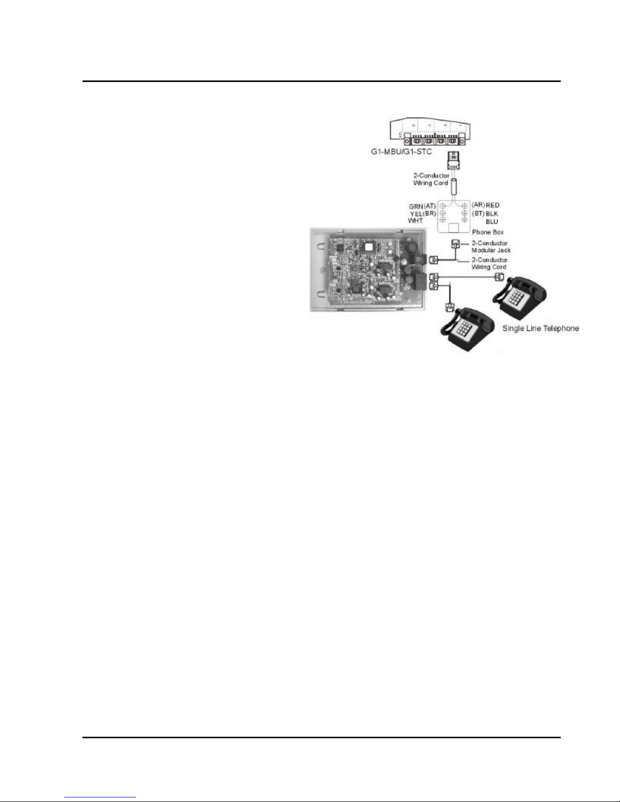
Single Line Telephone (connected to DKSLD)
A cable cover is provided with the KSU.
l
Station cables can enter from either the top
or bottom as desired. Remove one or both
ends of the cover as required and route the
station cable through the hole. Terminate
the station wires with the connectors that are
provided. The stations will connect to the
KSU as shown on the main panel (above) on
connector locations 11 – 28.
Connect Tip terminal with GRN terminal
l
(screws) of the modular jack, Ring with
RED.
There is no polarity requirement on Tip and
l
Ring.
2-conductor wiring is required for DK-SLD
l
Single Line Telephone Adapter.
Distribute two cords for two single line
l
telephones.
GDS-600 - General Description
29
Page 44
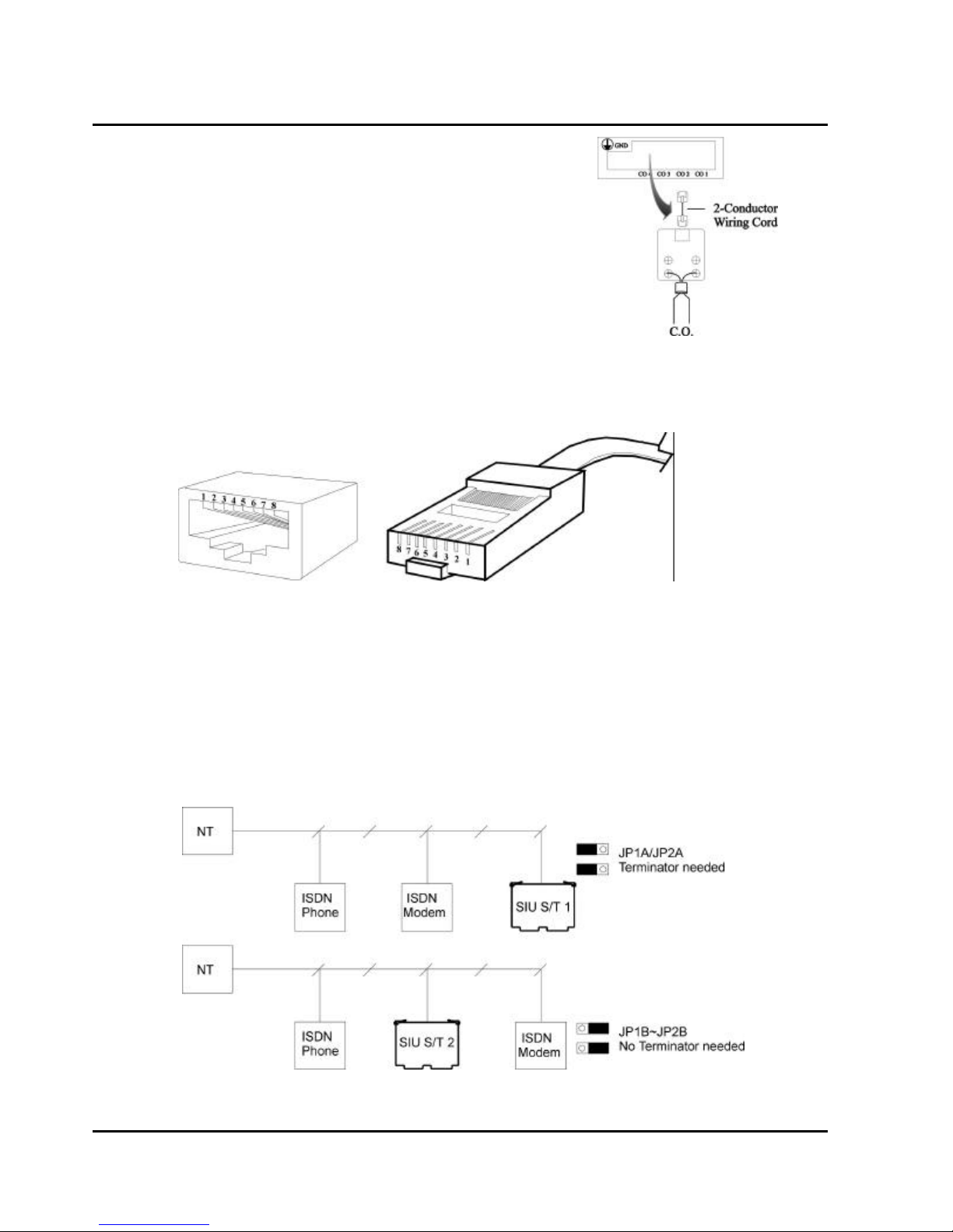
CO/PABX Connections
Make your CO line connection to the telephone company on this
l
connector. Pins 3 and 4 of the connector are for the CO line.
RJ-11C (2 wire) modular connector is required.
l
2-conductor wiring is required.
l
ISDN S/T Connections
Make your CO line connection to the telephone company on this
l
connector. Pins 3 to 6 of the connector are for the CO line.
Cable: Twisted 2 pairs
l
Connector Type: RJ-45 (4 wire) modular connector is required.
l
Connector PIN assignment: (Pin 1, 2, 7, 8 are reserved.)
l
Install/remove the terminators by adjusting the jumper JP1 (A, B, C) and JP2 (A, B, C) on SIU card. If there
l
is no other ISDN device connected after the ISDN interface of SIU card when using point to multi-point
connection, this ISDN interface port needs the terminator installed. Otherwise, remove the terminator.
Example:
The following is the point to multi-point connection.
. The 1st ISDN interface needs the terminator because there is no other ISDN device connected after
this ISDN interface of SIU card.
. The 2nd ISDN interface does not need the terminator because there is an ISDN Modem connected
after this ISDN interface of SIU card.
Adjust 8K/256K jumper on SIU for the ISDN line. Adjust it to 8K position for most ISDN lines.
l
30
Issue 1.5 / May, 2002
Page 45
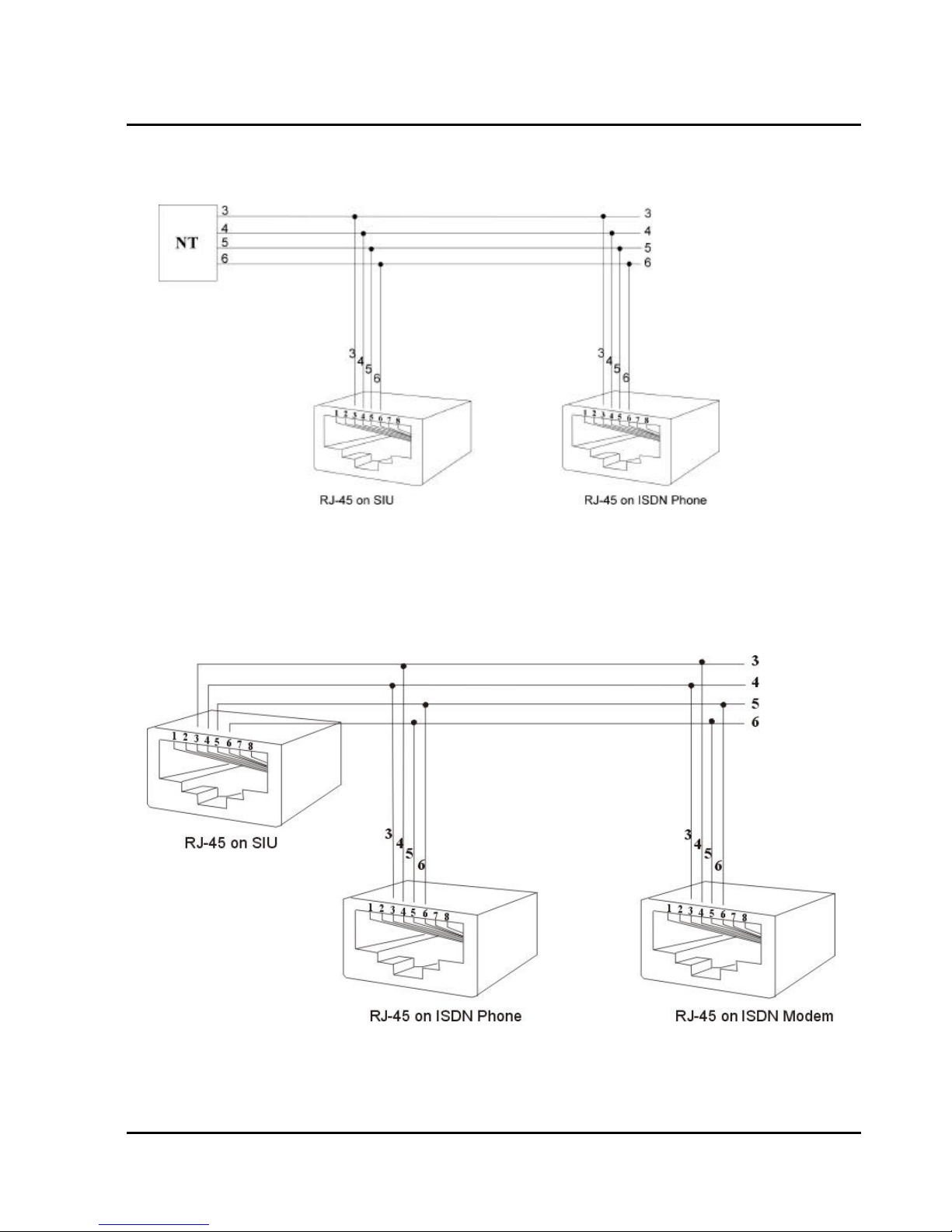
GDS-600 - General Description
T-Interface Connection:
l
If the user has programmed the ISDN interface of SIU to a T-Interface, the wiring should be as follows:
S-Interface Connection:
l
If the user has programmed the ISDN interface of SIU to a S-Interface, the wiring should be as the
following:
31
Page 46
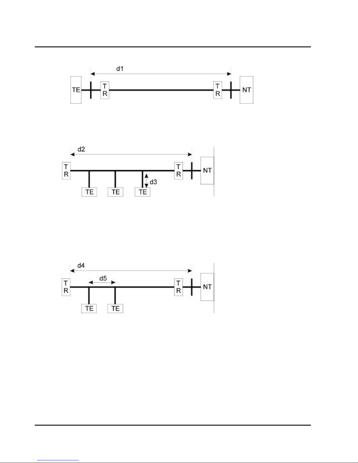
Bus Configurations on the S/T Interface:
l
Point to Point:
d1: 750m ~ 1000m; Length limitation by attenuation of 6dB at 96kHz.
Short Passive Bus:
d2: 100m ~ 200m; Length limitation by round trip delay 10us to 14us, not by attenuation.
d3: Recommendation with a cord having a minimum length of 5m and not more than 10m.(5md3
10m)
Extended Passive Bus:
d4: 500m ~ 800m; Length limitation by round trip delay 10us to 14us, not by attenuation.
d5: 25m ~ 50m; Length limitation between TE’s by differential round trip delay of 2us.
32
Issue 1.5 / May, 2002
Page 47
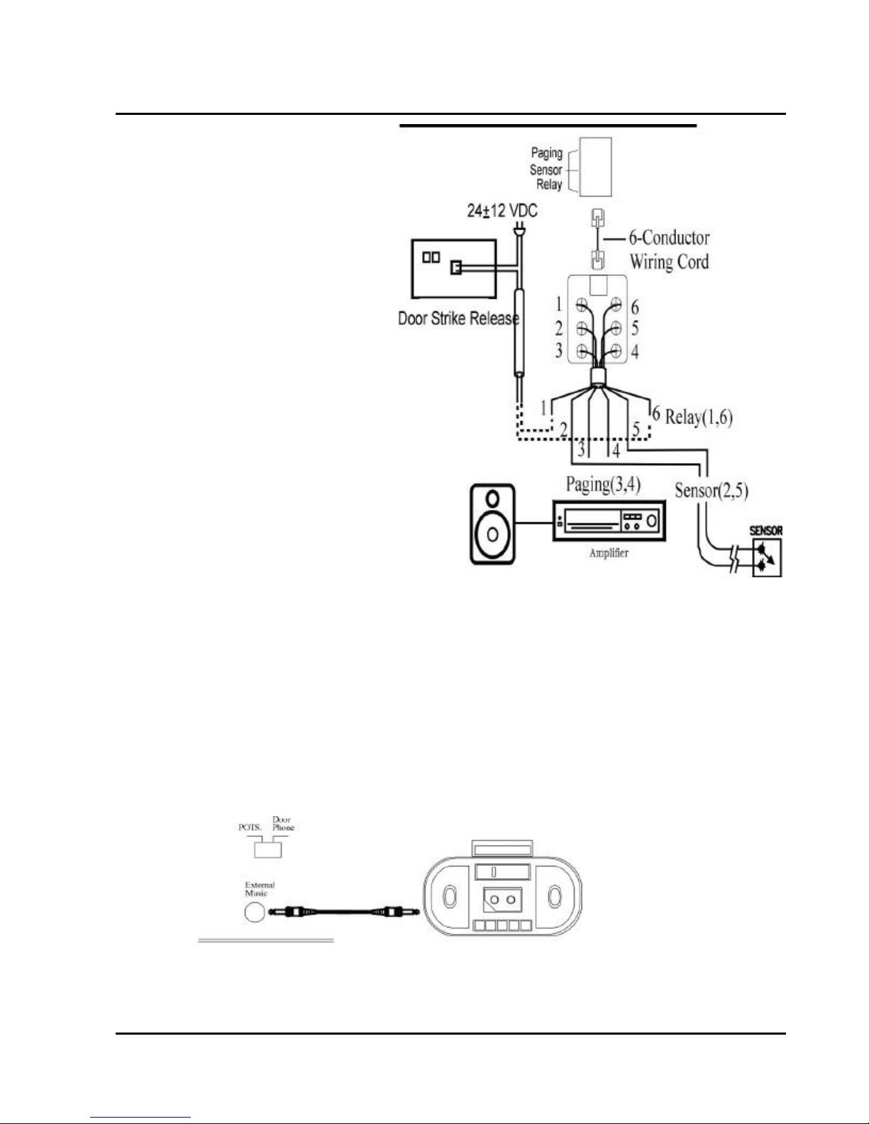
Optional Cabling
Connect a 6 conductor mounting cord from
the KSU to a RJ-25 modular block.
Door Switch (Relay) Connection
One Door Switch (24+-12VDC) may be
l
used on the G1-824 system.
2-conductor wiring is required.
l
Connect the door switch to pins 1 and 6
l
of the RJ-11 connector.
GDS-600 - General Description
Sensor Connection
The Sensor connector on G1-824 may
l
be used for the External Sensor input.
The sensor may be configured for
l
normally open or normally closed
operation.
2-conductor wiring is required.
l
Connect the sensor to pins 2 and 5 of
l
the RJ-11 connector.
Refer to System Programming Form 39
l
-- Sensor Assignment.
Paging Connection
The Paging connector on G1-824 may
l
be used for an External Paging input.
2-conductor wiring is required.
l
Connect the amplifier to pins 3 and 4 of
l
Door switch/Sensor/Paging cabling
the RJ-11 connector.
Refer to Illustration Door Switch / Sensor / Paging cabling:
Music on Hold Connection
• Connect the (optional) external music source to the external Music" input labelled on the KSU.
• Use a 1/8” mini plug to connect the music source to the KSU via an approved line isolation unit.
33
Page 48
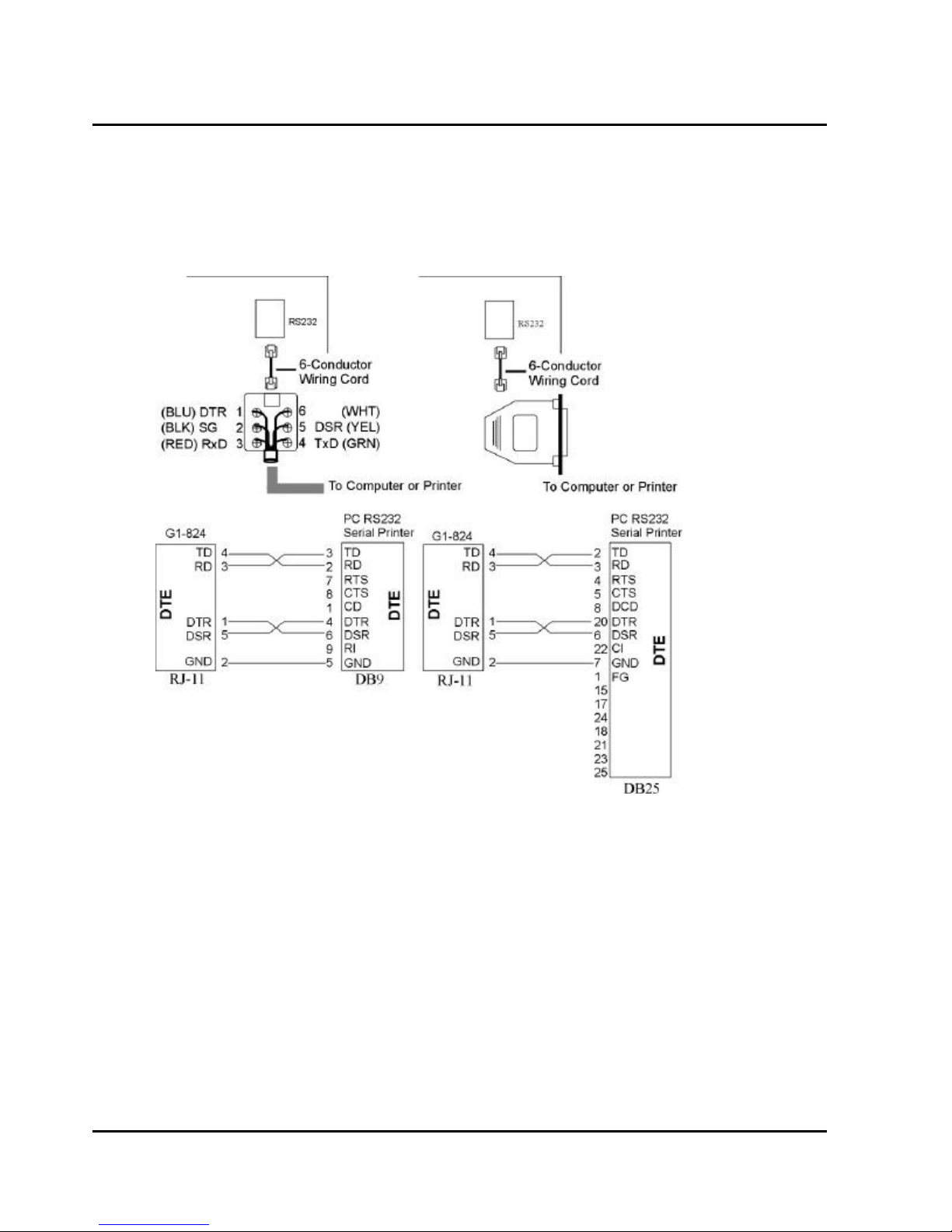
RS232 Port Connection
Use the RJ-11 connector to terminate the RS232 cable. Then connect the RJ-11 to the KSU with a 6 conductor
line cord. Insert the line cord into the connector labelled RS-232.
Notice: Don’t connect the RS232 cable over the length limitation (15M / 50 feet.)
34
Issue 1.5 / May, 2002
Page 49
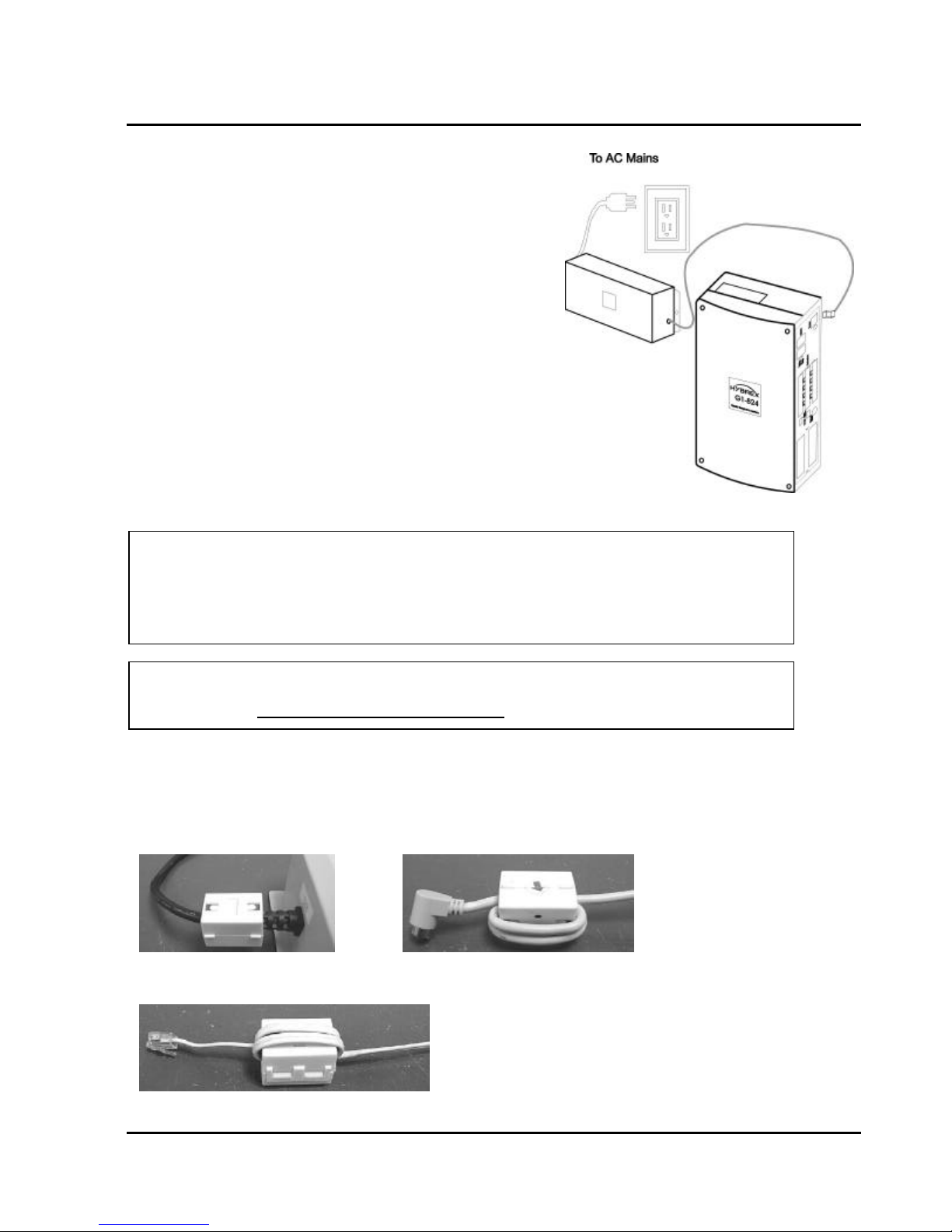
GDS-600 - General Description
Power On and Operational Test
Before connecting the G1-PWU to AC power:
Verify that input voltage and input voltage selection jumper
l
on G1-PWU are correct before you power up the system.
Recheck the cabling for incorrect connections, loose wires
l
and wiring fragments that may cause short-circuits.
Plug the power cord into a power outlet.
l
Verify the system boots properly by checking the display of
l
a telephone set.
You may now connect the battery back up unit if applicable.
l
Operational Tests
Check each telephone and CO line to verify that outgoing lines
are connected properly.
Check that intercom calls can be made from extension to
extension.
WARNING:
DISCONNECT THE POWER SUPPLY FROM THE AC POWER SOURCE BEFORE WIRING OR
CHANGING ANY WIRING.
Connect the Battery Backup AFTER AC power has been connected to the Power Supply.
Disconnect Battery Backup BEFORE disconnecting AC power from the Power Supply.
NOTICE:
ONCE THE SYSTEM OPERATES PROPERLY, PROCEED TO SYSTEM PROGRAMMING.
(REFER TO THE SYSTEM PROGRAMMING MANUAL.)
Special Immunity Protection for System and terminals
Adding Noise Filters to the points below can enhance the immunity capability of the system from outside
environmental noise.
For Power Supply:
For Line:
35
Page 50

GENERAL DESCRIPTION
G2-1648
36
Issue 1.5 / May, 2002
Page 51
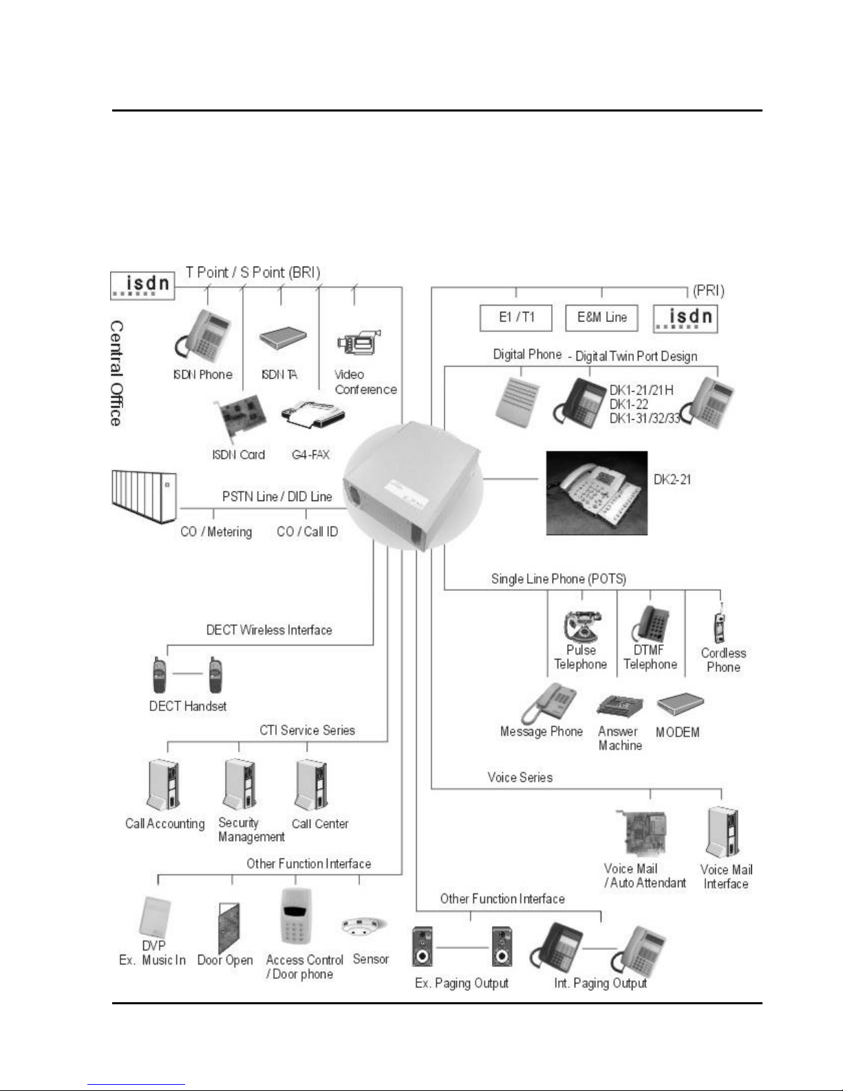
GDS-600 - General Description
Description - G2-1648
The G2-1648 is an advanced ISDN Digital hybrid telephone system employing a microprocessor stored program
and digitally controlled solid state Time-division switching. The G2-1648 system is specifically designed for
small business as well as residential applications. At the forefront of the system design is a universal concept to
adapting and connecting with a variety of communications devices. Productive HYBREX Digital Key
Telephones offer thoughtfully designed productive feature access to keep you connected with one another and
customers. Auto Telecom technology leads the industry in providing for compatibility with devices such as fax
machines, answering machines, cordless phones, computer modems and other office/home equipment.
37
Page 52
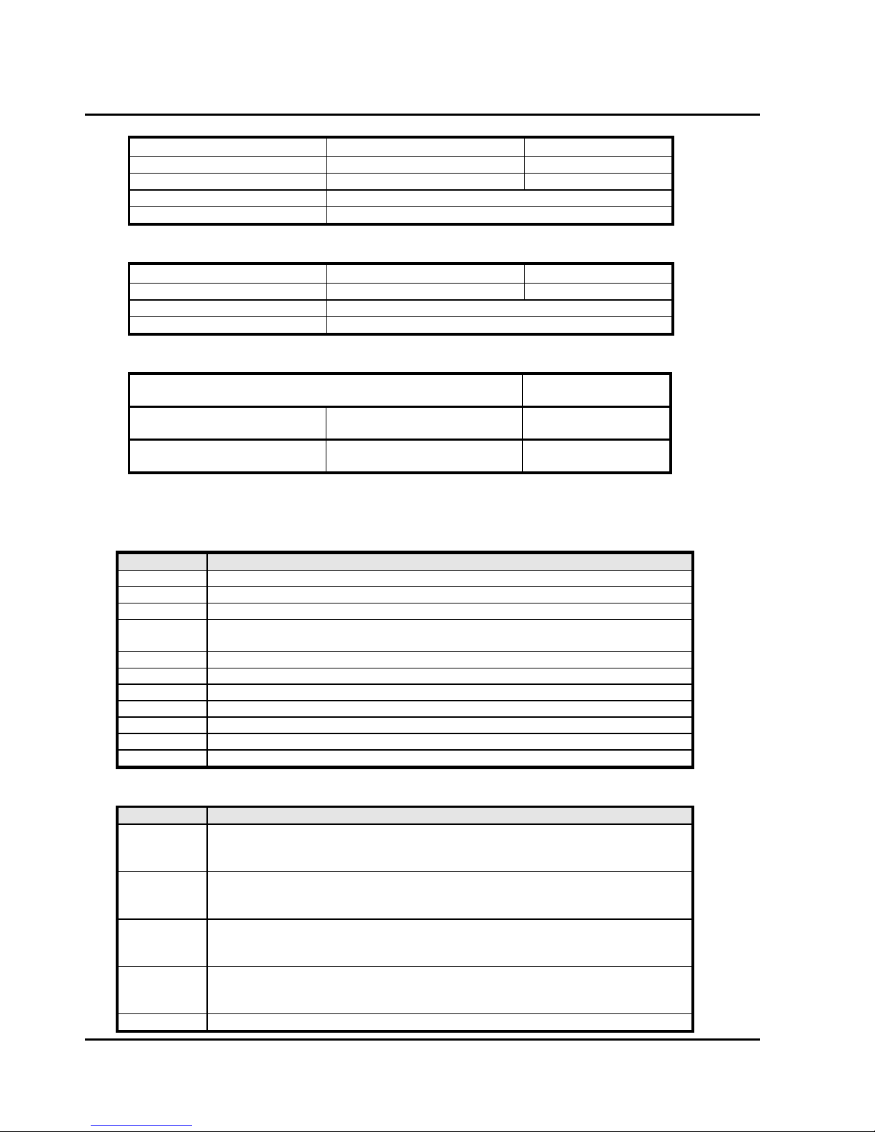
Multifunction Key Telephone. Includes speakerphone, headset jack, 20 dual
Mechanical Specifications (Key Service Unit)
CABINET DIMENSIONS
XXXmm W XXmm D XXXmm H
XXX” "
WEIGHT XX Kg (Configuration: 4 x 8)
XX lbs
Mechanical Specifications (Battery Back Up Housing)
CABINET DIMENSIONS
15.5” W 3.0” D 5.75” H
WEIGHT With Batteries -16 lbs Without Batteries- 4 lbs.
Mounting Screws 12.25” center to center
Environmental Specifications
OPERATING CONDITIONS STORAGE
Temperature 0º to 45º C -40º to 66º C
(32º to 113º F) (-40º to 150º F)
Humidity 10 to 95% relative 10 to 95% relative
Non-condensing non-condensing
Parts & Peripherals
CONDITIONS
System Modules
Model
Description
G2-MMD KSU with Power Modular
G2-MPU G2 128/144/300/600 Main CPU Controller
G2-IPU G2-1648 Main CPU Controller / G2 128/144/300/600 Interface Control Card.
G2-MSU Multi-Service Card (External Paging/ Relay/ Sensor / RS232/ MODEM
Interface/ Door Phone / External MOH Interface)
G2-TKU Trunk Card : 4 CO lines
G2-PIU ISDN PRI Interface: 24 Channels Maximum
G2-SIU-2 ISDN S/T interface with 2 circuits
G2-SIU-3 ISDN S/T interface with 3 circuits
G2-STU Station Card : 4 Digital Twin-ports
G2-SLU Single Line Card : 8 SLT ports
G2-PWU G2 Power Supply
Type of Phones
Model
Description
DK1-21H Multifunction Key Telephone. Includes 32 character LCD display, single line
telephone port, speakerphone, handsfree, headset jack, 20 dual color keys
and 14 function keys for feature access, DSS, CO Lines and speed dial.
DK1-21 Multifunction Key Telephone. Includes 32 character LCD display,
speakerphone, handsfree, headset jack, 20 dual color keys and 14 function
keys for feature access, DSS, CO Lines and speed dial.
DK1-22 Multifunction Key Telephone. Includes speakerphone, handsfree, headset
jack, 20 dual color keys and 14 function keys for feature access, DSS, CO
Lines and speed dial.
DK1-31 Multifunction Key Telephone. Includes 32 character LCD display,
speakerphone, headset jack, 20 dual color keys and 14 function keys for
feature access, DSS, CO Lines and speed dial.
DK1-32
38
Issue 1.5 / May, 2002
Page 53
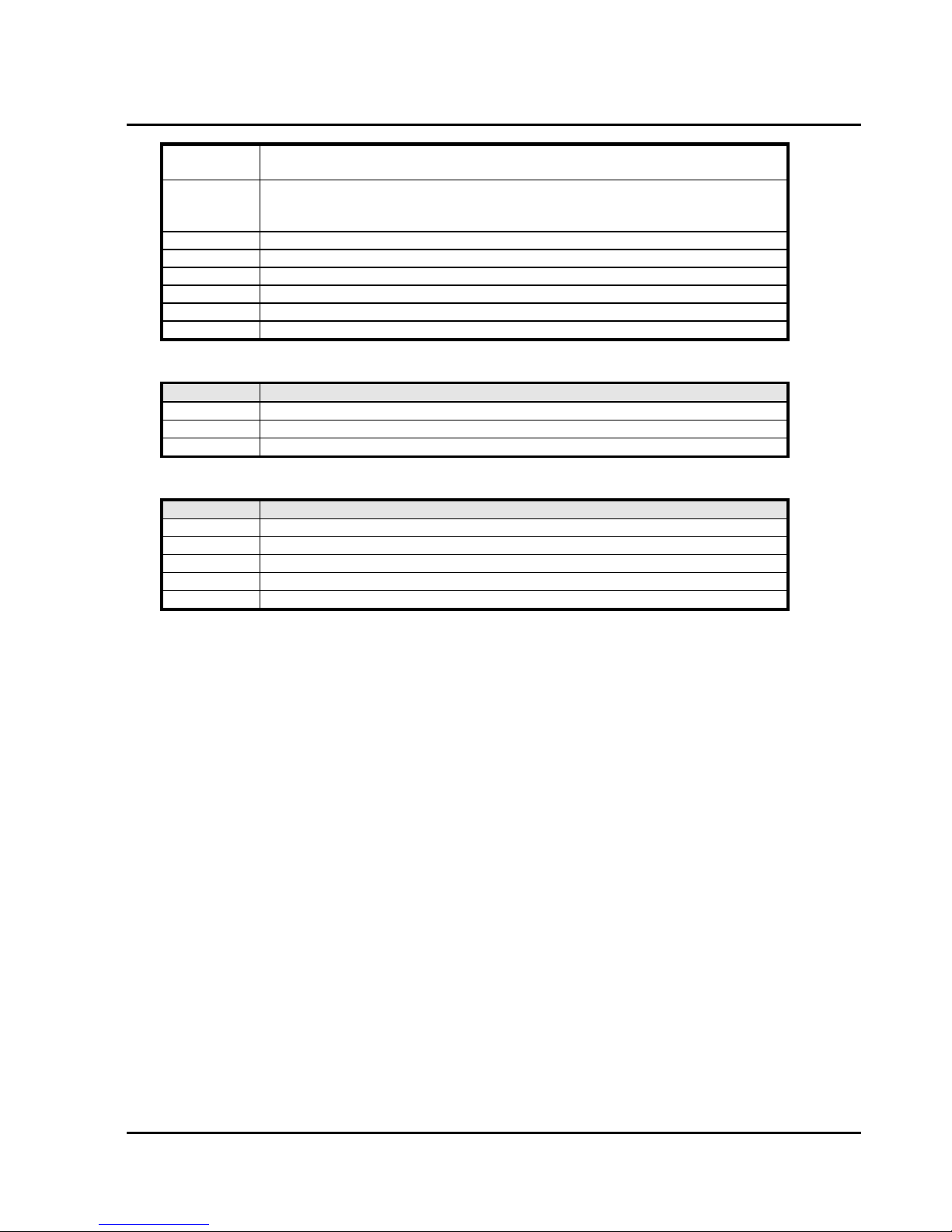
color keys and 14 function keys for feature access, DSS, CO Lines and speed
dial.
DK1-33 Multifunction Key Telephone. Includes speakerphone, headset jack, 8 dual
color keys and 14 function keys for feature access, DSS, CO Lines and speed
dial.
DK1-SLC DK1 Keyphone - SLT port for DK1-2x series
DK-SLD Two Port SLT device – Convert a Digital port to two POTS ports
ACP Access Control Phone
ACP/RF Access Control Phone with RF Proximity Card function
PX-Card RF Proximity Card for ACP/RF
WMU-12 Wall Mount Kit for DK1 Series Telephones
Peripheral Devices
Model Description
DPU05 Door Phone - 2 Wires
BBOX0 Battery Box without Batteries
BBOX1 Battery Box with Batteries
Optional Interface Cards
Model Description
G2-VMU Voice Mail Unit (4 Channels) / Auto Attendant / Wake-up / Message Waiting
G2-LMU LAN Management Unit
G2-CIC-D Caller ID Card for G2-TKU – Dual Mode (FSK/DTMF)
G2-CIC-F Caller ID Card for G2-TKU – FSK Mode
G1-MDC 4 Channel Metering Card for G2-TKU
GDS-600 - General Description
39
Page 54

System Installation - Introduction
This section provides directions for installing the system and optional equipment.
The installation must be performed by qualified service personnel.
Main components of the system are:
Key Service Unit, which includes:
• Power Supply Unit (G2-PWU)
• Main KSU (G2-MMU)
• CPU Unit (G2-IPU)
• Multi-Service Unit (G2-MSU)
• Trunk Unit (G2-TKU / G2-SIU / G2-PIU)
• Digital Station Unit (G2-STU)
Optional Expansion Cards:
• Trunk Card (G2-TKU / G2-SIU / G2-PIU)
• Digital Station Card (G2-STU – four digital twin
port circuits)
• Single Line Station Card (G2-SLU – eight single
line port circuits)
• G2-CIC Card (Caller ID Card - four port circuits)
• Voice Mail Unit (G2-VMU)
• LAN Management Unit (G2-LMU)
• Metering Card (G1-MDC)
NOTE: Please follow the directions step by step. The
GDS-600 system should be installed in strict accordance with this manual.
40
Issue 1.5 / May, 2002
Page 55
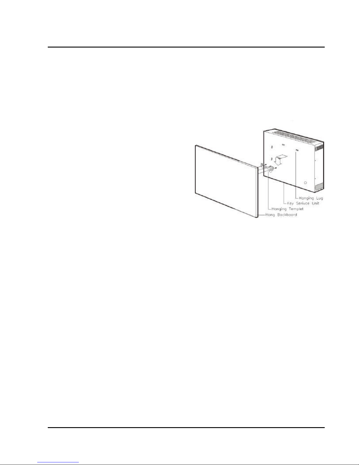
G1-824 Programming Manual
Installation
Caution 1. This system should be installed by qualified service personnel.
4. Do not install the Power Supply unless you have read the following instructions
and completed all the installation and wiring.
5. STATIC SENSITIVE DEVICES! Please handle with care.
Installing the Equipment
Backboard
Be sure to plan and allow enough space to mount and
connect the key service unit, power supply and system
battery back up if applicable.
Key Service Unit
Use the enclosed Hanging Template to locate the
mounting position for the Key Service Unit. Drill
appropriately spaced holes to fix the Hanging Template
and mount the KSU on the wall. When mounting the
KSU, make certain that there is adequate room for the
future system expansion and that the connecting power
cable between the power mains and the KSU. The same
applies for the battery back up unit.
Power Supply
Dedicated Power Source - The power supply must be connected to a dedicated AC outlet.
Be sure that the third wire earth ground of the AC circuit is connected to a good electrical ground. If a music
source is installed, it must be connected to a separate AC circuit rather than the system's dedicated AC line
cord.
Check Your Voltage Selection Jumper
Verify that the input voltage and input voltage jumper are correct before you power on the system. The input
voltage is set according to the Customer's requirement before shipping. However it is important to verify that
the setting is correct prior to initial system power up.
Power Supply voltage options for the unit:
100-VAC: 100 to 120 V AC (50/60Hz) or 240-VAC: 205 to 265 V AC (50/60Hz).
Installing expansion and optional cards
In this step you will be installing printed circuit cards on to slots of the main board in the basic cabinet. Take
your time and extra care to assure the printed circuit cards are properly aligned. After installing each option and
expansion card, perform a visual inspection to assure the printed circuit card is installed properly.
4. Remove the 4 screws located at the corners of the cabinet and lift the front cover off.
5. Install the specific cards into the dedicated slots of G2-MBU as below card introduction.
41
Page 56
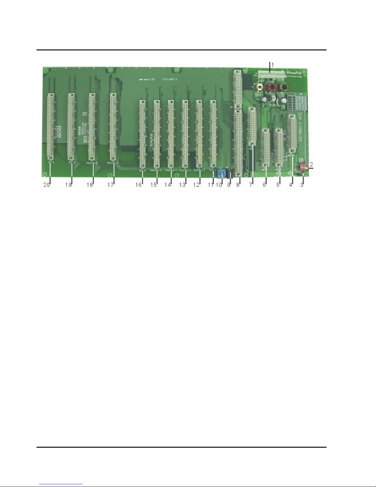
Card Introduction
1.) CN1: Power socket to connect to the main power unit (G2-PWU)
2.) JP1: Reset jumper for flash memory
3.) SW1: Cabinet position selection
4.) CN2: LNU/MPU slot
5.) CN3: VMU 1 slot
6.) CN4: VMU 2 slot
7.) CN5: MSU slot
8.) CN6: IPU slot: G2-IPU slot
9.) CN8: DC power output
10.) CN9: Cabinet grounding for expansion
11.) CN12: STU 1 slot
12.) CN13: STU/SLU 2 slot
13.) CN14: STU/SLU 3 slot
14.) CN15: STU/SLU 4 slot
15.) CN16: STU/SLU 5 slot
16.) CN17: SLU slot 6
17.) CN18: TKU/SIU/PIU 1 slot
18.) CN19: TKU/SIU 2 slot
19.) CN20: TKU/SIU 3 slot
20.) CN21: TKU/SIU 4 slot
42
Issue 1.5 / May, 2002
Page 57
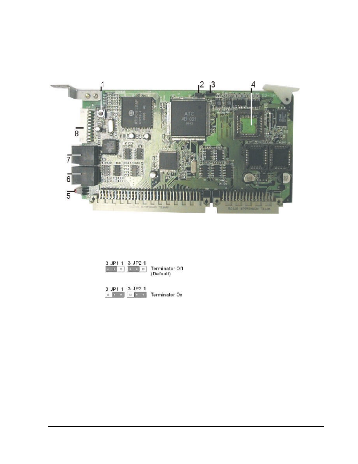
Installing CPU and option cards (continued)
G2-IPU
G1-824 Programming Manual
1.) SW1: Reset button
2.) JP1: Terminators for bus expansion of multi-cabinet.
3.) JP2: Terminators for bus expansion of multi-cabinet.
4.) Socket for the HDLC controller for bus expansion of multi-cabinet.
5.) LED1: Heart beat LED
6.) CN6: connector for expanding cabinet
7.) CN5: connector for expanding cabinet
8.) CN9: LCD connector
43
Page 58
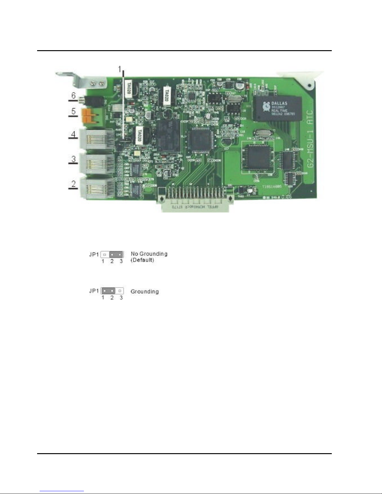
G2-MSU- Multi Service Card
1.) JP1: Grounding Jumper for some specific external paging device
2.) MODEM connector for the external MODEM connection to the system
3.) RS232 connector
4.) Relay / Sensor / External Paging connector
5.) CN3: Door Phone Interface (for DPU05)
6.) CN2: External Music on Hold Interface
44
Issue 1.5 / May, 2002
Page 59
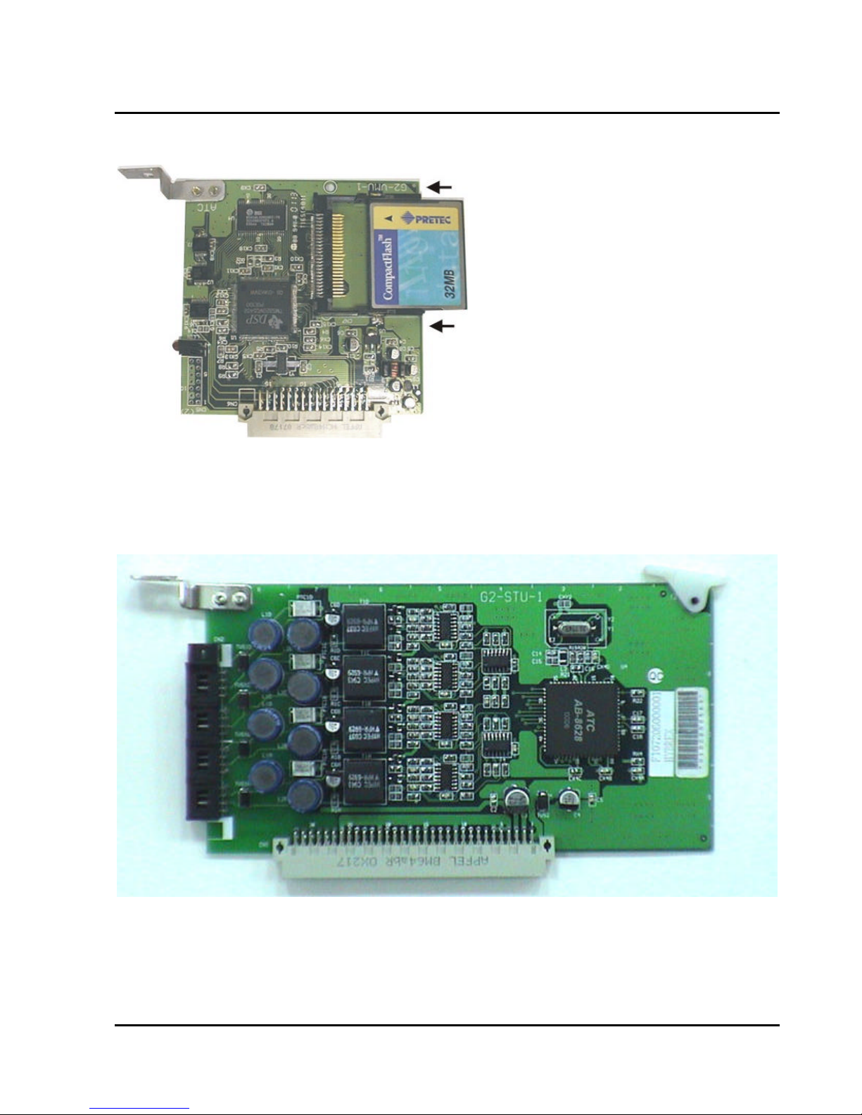
G2-VSC- Voice Service Card
G2-STU Digital Station Card
Install this G2-STU card on STU1, STU/SLU2, …, STU/SLU5 slot of the G2-MBU.
l
G1-824 Programming Manual
45
Page 60
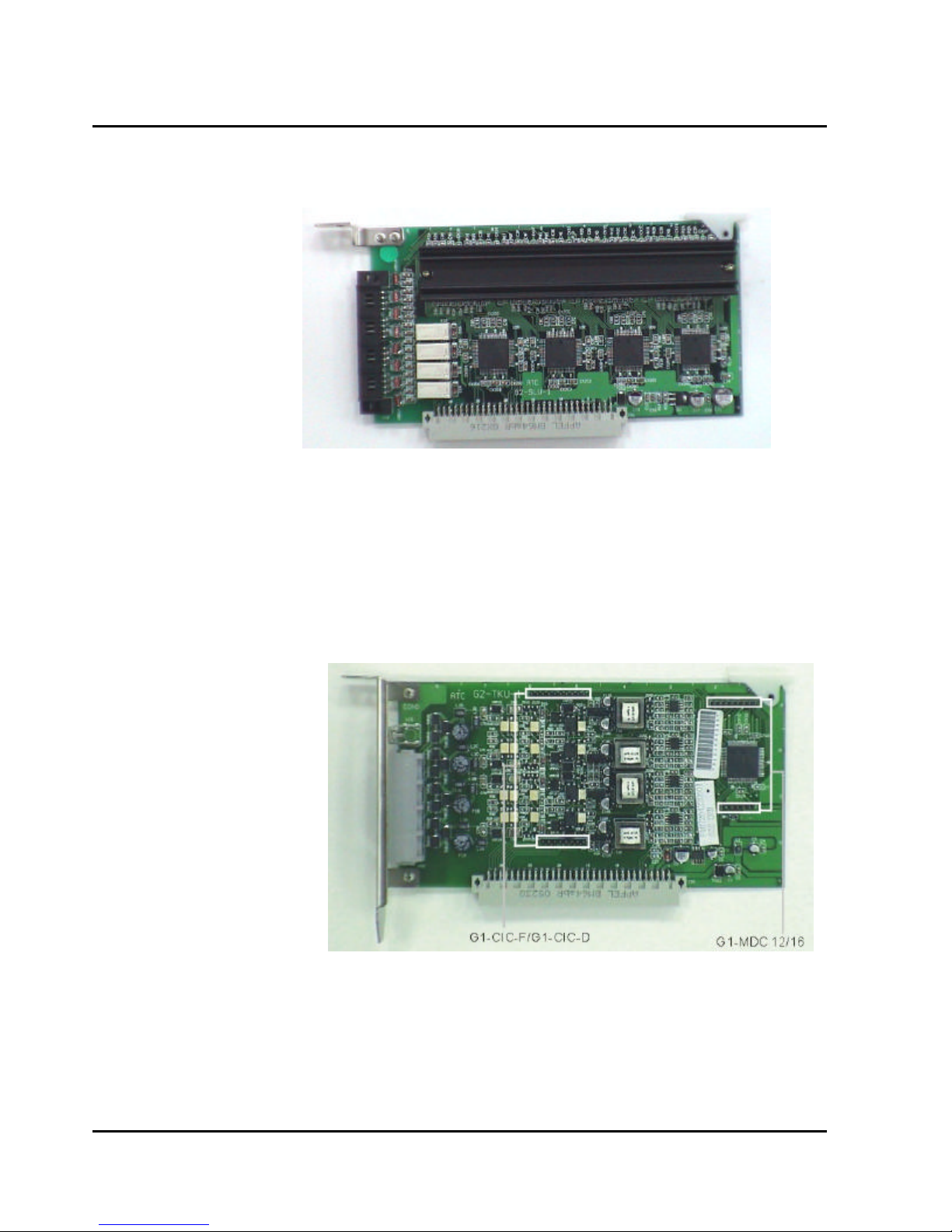
G2-SLU Analog Station Card
Install this G2-SLU card on STU/SLU2, …, STU/SLU5, SLU6 slot of the G2-MBU.
l
G2-TKU- 4 Port CO Line Card
Install G1-CIC card or G1-MDC card on G2-TKU (optional).
l
Install this G2-TKU card on TKU1/TKU2/TKU3/TKU4 slot of the G2-MBU.
l
Connect an attached cable between CN4 of G2-TKU to CN3 of G2-SLU for power failure transfer.
l
CN6/CN7: G1-CIC-D/G1-CIC-F
CN2/CN3: G1-MDC 12/16
46
Issue 1.5 / May, 2002
Page 61
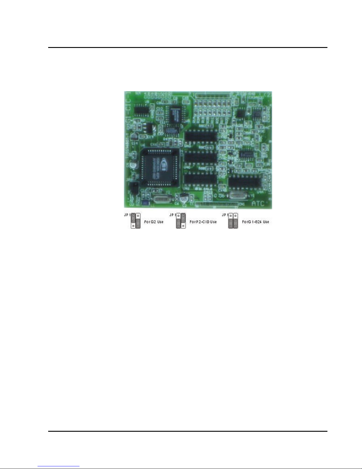
G1-824 Programming Manual
G2-CIC- Caller ID Card
Adjust JP1 of G1-CIC card for G2 use. And then install G1-CIC card on CN6/CN7 of G2-TKU card. Miss
l
alignment could damage both cards or the system.
47
Page 62
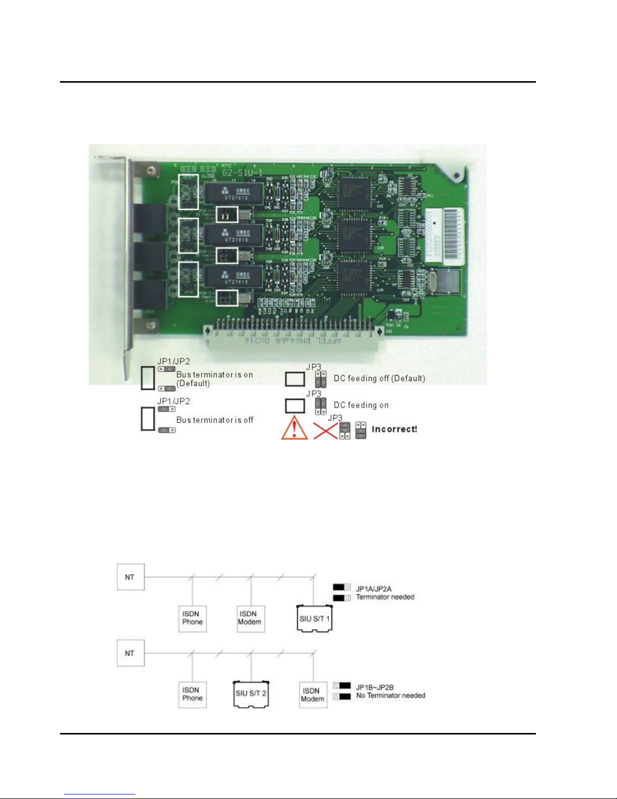
G2-SIU ISDN S/T Interface Card
Install this G2-SIU card on TKU1/SIU1 or TKU2/SIU2 slot of the G2-MBU.
l
JP3(A,B,C): DC feeding jumper. Default is no DC output. If the internal ISDN device does not offer local power
and need DC feeding to work. The related jumper of this internal ISDN interface needs to be set to “on”.
Caution:
1. When this jumper is on, users cannot loop “S” interface back to another “T” interface for testing purpose.
Otherwise, it will damage this card!
2. Incorrect jumper set will also damage this card.
JP1(A,B,C)/JP2(A,B,C): Bus Terminator.
48
Issue 1.5 / May, 2002
Page 63
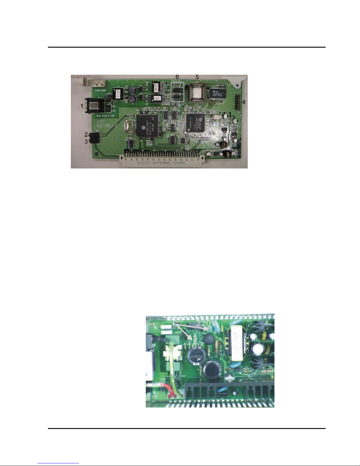
G2-PIU ISDN PRI / T1 / E1 Interface Card
Install this G2-PIU card on TKU1/SIU1 slot of the G2-MBU.
l
G1-824 Programming Manual
1. RJ 45 Connector:
Pin 1,2: for TX.
Pin 4,5: for RX.
2. LED 2: For Sync with network.
1. Off: No connection.
2. Flash: There are some troubles to sync.
3. On: Sync OK.
3. LED 1: For the heart bead of DSP chip.
4. CN7: For test purpose.
5. DSP chip for T1/E1 interface.
6. CN4/CN5:
Jumpers on CN4 is for E1 interface and ISDN PRI/E1 interface.
Jumpers on CN5 is for T1 interface and ISDN PRI/T1 interface.
Voltage Selection Check
Make a check to assure the power supply jumper setting is for the proper voltage.
l
When complete, place the power supply cover back on the power supply.
l
49
Page 64
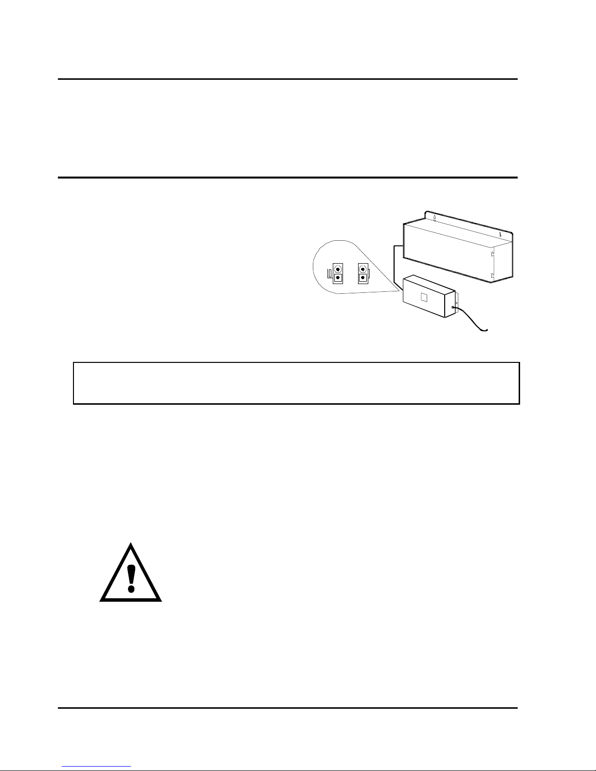
Replace Cover
With the expansion and option cards installed and the battery insulator removed, replace the cover and install
the 4 screws removed earlier.
This concludes the installation of expansion and option cards!
Preparing The External Battery Backup
The Key Service Unit has two external backup
batteries in series (12 volts each) for emergency power
when a power failure takes place. The G2-1648
requires 2 x BB0X1 units for battery backup.
If you are installing the optional Battery Backup
(BBOX1 x 2), make certain that there is adequate room
for their installation. Make certain that the Battery
Backup is mounted close enough to the Power Supply
that the interconnecting cables between the Battery
Backups and the Power Supply can connect.
Do Not Connect the Battery Backup at this time!
Do Not Connect the Battery Backup at this time! Battery Backup should not be
connected to the System power supply until all power up testing has been
completed!
Charging the Battery
The rechargeable batteries are automatically charged when the KSU is plugged in.
When System is in a full-load condition (eight CO Trunks and twenty-four Extensions all in use), the batteries
provide a minimum of 1 hour's consecutive use. Change the batteries every two years.
Installing or Replacing Batteries
Caution
To Reduce the Risk of Fire or Injury to persons, Read and Follow these Instructions.
This product is defined as a secondary battery operated device. As such, the following instructions
1. Charge the batteries provided with or identified for use with this product only in accordance with the
1. Use only the following type and size batteries:
12 Volt 6.5 Amp/Hour "Gel-Cell" sealed batteries (2).
Dimensions, approximately 3 1/4" (H), 5 15/16" (W), 2 1/2" (D).
PowerSonic model PS660 or equivalent.
2. Do not dispose of the batteries in a fire. The cell may explode.
Check with local codes for possible special disposal instructions.
5. Do not open or mutilate the batteries. Released electrolyte is corrosive and
may cause damage to the eyes or skin. It may be toxic if swallowed.
6. Exercise care in handling batteries in order not to short the battery with
conducting materials such as rings, bracelets, and keys. The battery or conductor may overheat and cause
burns.
should also be read and followed:
50
Issue 1.5 / May, 2002
Page 65
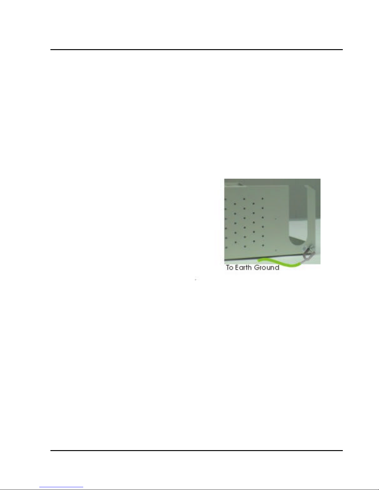
G1-824 Programming Manual
instructions and limitations specified in this manual.
2. Observe proper polarity orientation between the batteries and battery charger.
3. Do not mix old and new batteries in this product.
4. Do not mix batteries of different sizes or from different manufacturers in this product.
Before installing or replacing batteries, disconnect the battery supply unit to the KSU by removing the polarized
battery connector at the KSU. Due to the weight of the batteries, it is advised that the battery cabinet be
removed from the wall before working on it.
System Ground
It is strongly recommended that the system be grounded by connecting a heavy, insulated copper wire (e.g.,
14AWG or larger) between the grounding bolt on the right-lower side of the cabinet and an earth ground.
Without this System Ground there is no protection against lightning damage to Co lines and warranty will be
voided.
Do not connect the grounding wire of the KSU to a computer, telex, or any other external device.
Refer to the wiring diagram located on the inside of the cable cover for all connections
Connecting Stations
The station cabling for the G2-1648 should be a home run from the jack to the telephone room. The termination
should be at conventional 66 type connecting blocks or Krone or directly to the provided station connectors.
One pair twisted wiring is required for each station location. Attention to proper cabling will go a long way
towards a successful installation and minimizing service calls after installation. Some guidelines for running
station cable are as follows:
Avoid running cable parallel to fluorescent light fixtures or electrical lines not in conduit. If these obstacles
l
are unavoidable, run the cable at right angles across them.
Do not run station cable inside conduit already occupied by electrical wiring.
l
Do not run station cable near equipment with electric motors or strong magnetic fields.
l
Do not place station cable on the ground where it can be stepped on or rolled over by office furniture or
l
office equipment.
51
Page 66
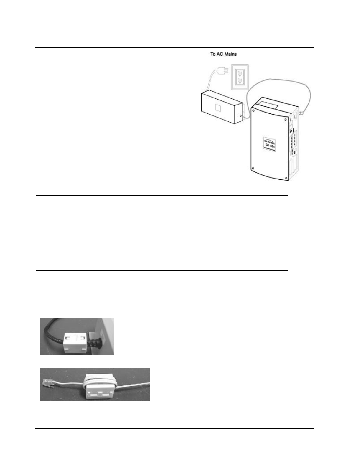
Power On and Operational Test
Before connecting the G2-PWU to AC power:
Verify that input voltage and input voltage selection jumper
l
on G2-PWU are correct before you power up the system.
Recheck the cabling for incorrect connections, loose wires
l
and wiring fragments that may cause short-circuits.
Plug the power cord into a power outlet.
l
Verify the system boots properly by checking the display of
l
a telephone set.
You may now connect the battery back up unit if applicable.
l
Operational Tests
Check each telephone and CO line to verify that outgoing lines
are connected properly.
Check that intercom calls can be made from extension to
extension.
WARNING:
DISCONNECT THE POWER SUPPLY FROM THE AC POWER SOURCE BEFORE WIRING OR
CHANGING ANY WIRING.
Connect the Battery Backup AFTER AC power has been connected to the Power Supply.
Disconnect Battery Backup BEFORE disconnecting AC power from the Power Supply.
NOTICE:
ONCE THE SYSTEM OPERATES PROPERLY, PROCEED TO SYSTEM PROGRAMMING.
(REFER TO THE SYSTEM PROGRAMMING MANUAL.)
Special Immunity Protection for System and terminals
Add Noise Filter for below points can enhance the immunity capability of system from outside environment
noise.
For Power Supply:
For Line:
52
Issue 1.5 / May, 2002
Page 67

G1-824 Programming Manual
PROGRAMMING INFORMATION
53
Page 68

Model G1-824/G2-1648 - Programming Manual
Programming Information
This document contains the system forms required to program the G1-824 and an explanation of the
parameters.
New Systems
We recommend that all new systems have the system memory reset before system programming takes place.
This ensures that any extraneous information that may be present in system memory is erased and that the
system database will not be corrupt.
To Reset System Memory.
Enter System Programming :
From an LCD equipped HYBREX DK1-21(H)/DK1-31 Digital Telephone Set:
1. Press [PRG]. Press [7].
2. Enter Password if programmed. (New systems will not have a system password).
3. Press [SAVE].
4. LCD display will show:
PROGRAM MODE: __
(01 – 90)
5. Enter [2][5]. Press [SAVE]. Display will show:
25- Reset Data
0-9 Default
6. Enter [2].
7. System Database is now reset. LCD will display:
PROGRAM MODE: __
(01 – 90)
8. You may commence database entry at this point, or exit system programming by pressing SPK key
or by lifting and replacing the handset.
To Enter System Programming:
1. Press [PRG]. Press [7].
2. Enter Password if programmed. (New systems will not have a system password).
3. Press [SAVE].
4. LCD display will show:
PROGRAM MODE: __
(01 – 90)
5. You may begin system programming at this point.
54
Issue 1.5 / May, 2002
Page 69

G1-824 Programming Manual
Basic Programming Commands:
For the first time or infrequent installer, a programming overlay is provided with each Key Service Unit. This
overlay, when placed on a HYBREX LCD telephone set indicates keys used during programming for easy
reference. Experienced installers may program without the overlay. Both key designations are listed below.
Note: Keys listed between [ ] indicate the default keys shown on a telephone set. Keys listed between
{ } indicate keys displayed by the programming overlay. See illustration Programming
Overlay on the next page.
These commands are active while in the system programming mode
[F4]{PRG} Moves to the Top Level Programming Mode Display (does not save information
entered into any field unless [SAVE] is pressed first).
[F3]{SAVE} Commits the data that is showing on the LCD display into the system database.
[DSS 1]{PREV} Moves to the previous section of any multiple part form.
[DSS 2]{NEXT} Moves to the next section in any multiple part form.
[DSS 3]{LEFT} Moves the programming cursor to the left.
[DSS 4]{RIGHT} Moves the programming cursor to the right.
[DND/CN]{DON’T CARE} Enters a Wild Card (don't care) into Account Codes or Toll control
entries. LCD will display d (lower case letter "d") to indicate don't care entry.
[HOLD]{PAUSE} Inserts a Pause when programming a Speed Dial Entry or for Voice Mail
Programming. LCD will display p (lower case "p") to indicate a Pause entry.
[TRF/FL]{FLASH} Enters a FLASH command as part of a Speed Dial Entry. LCD will display F
(upper case "F") to indicate a Flash command. Clears a digit during other entries (Passwords,
etc).
[MSG]{P->T} Enters a command to convert from pulse dialling to DTMF dialling into a Speed
Dial Entry. LCD will display T (upper case "T") to indicate a tone conversion command.
[MIC/AT]{CHANGE} CHANGE key. Depending on form, it will cycle through available
Programming parameters.
[TRF/FL]{CLR DIGIT} Enters a FLASH command as part of a speed dial number. Clears a
digit during other entries (Passwords, etc).
[SPK]{EXIT} Exits Programming. Returns telephone to normal idle mode.
[REDIAL]{CLR ALL} Clears all digits on an entry such as speed dial or account codes.
55
Page 70
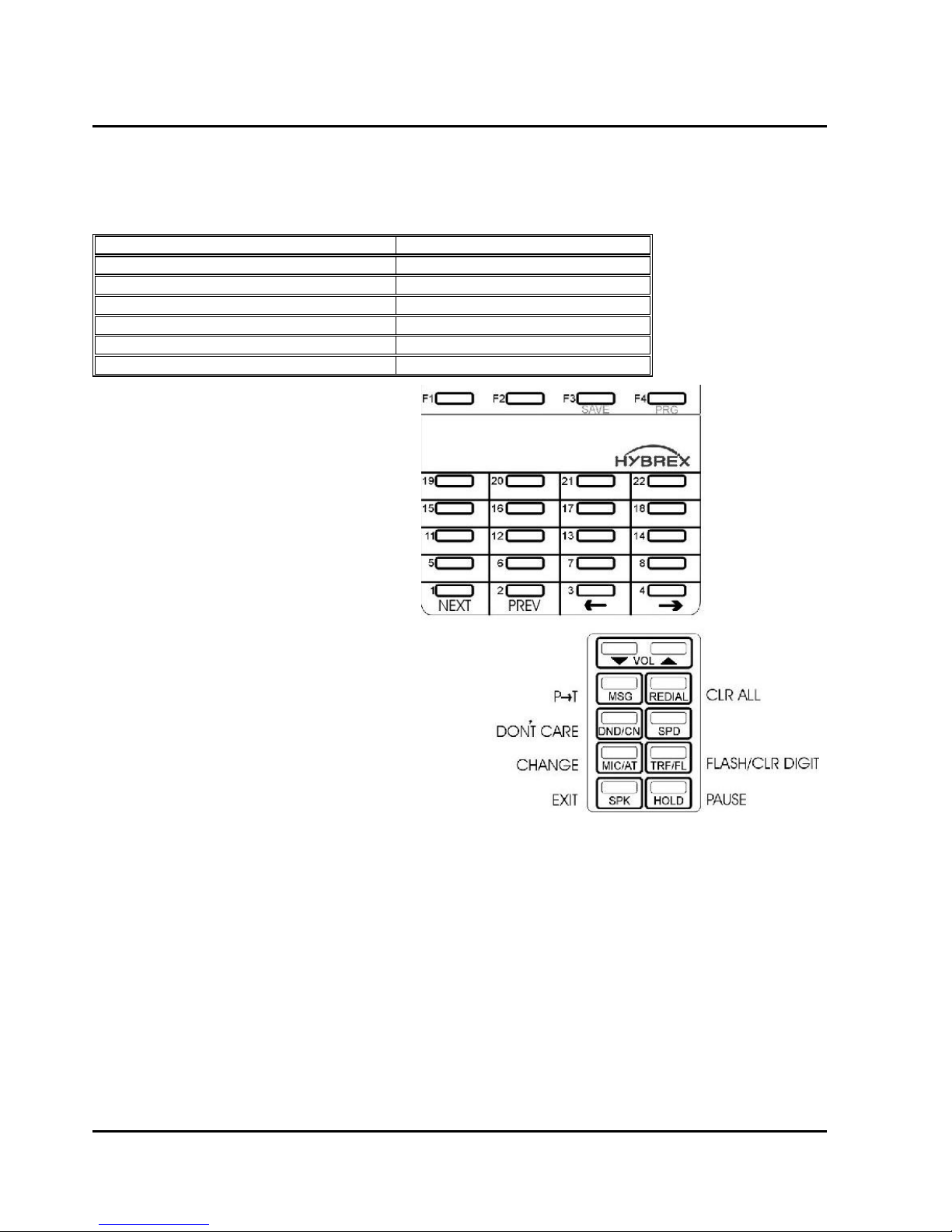
Alphanumeric Entry:
The following table indicates the capabilities of the name programming functions if they are selected on the
system. System Speed Dial, Personal Speed Dial, Stations, CO Lines and Sensors may be programmed with
names.
Key 1 = (Blank Space) – 1 Key 2 = A - B - C – 2
Key 3 = D - E - F – 3 Key 4 = G - H - I – 4
Key 5 = J - K - L – 5 Key 6 = M - N - O – 6
Key 7 = P - Q - R - S – 7 Key 8 = T - U - V – 8
Key 9 = W - X - Y - Z – 9 Key 0 = (Period). : & – 0
Key # = ( ) $ # Key * = (Dash) / ! *
DSS Key 1 = Backspace Cursor (Left) DSS Key 2 = Cursor Forward
If an entry is made that is not within valid
system parameters, the HYBREX system will
not accept the entry when [SAVE] is pressed.
The Speaker on the programming set will return
a busy tone and the LCD Display will place the
programming cursor under the offending entry.
You may make corrections and press [SAVE]
again. If multiple errors are made, the system
will continue to return you to the illegal entries
as others are corrected.
It is not necessary to re-enter existing
information on a multi-item form. You need
enter only the information that is to be changed.
You may move the cursor to the left or right in
order to access only the specific entry that you
want to change. You may press [SAVE]
without regard for the placement of the cursor
on the LCD display.
56
Issue 1.5 / May, 2002
Page 71

G1-824 Programming Manual
PROGRAM MODES
57
Page 72

Program 01-tk-IP : Day Ringing And Ringing Line Preference Assignment
01-tk-IP FLX DAY
11 12 13 14 15
General:
This program assigns each incoming line to ring the programmed stations. The ringing methods can be LINEAR
(ring the first available station), CIRCULAR (Ring the next station following the last station who just answered an
incoming call), HUNT (Ring the first assigned station for a set period of time (program mode 05-08-01) then if
no answer ring the next ring assigned station then the next etc.) or COMMON AUDIBLE (All stations will ring
simultaneously). See Program Mode: 35-tk-07 to assign. An overflow Ring Hunt Group can be assigned to
make additional stations ring after a time interval in addition to this ring assignment. See program Mode 2907/08.
Description:
1. This program sets Day Time ringing.
2. The station number can be 2,3,4 digits.
3. A total of 16 stations can be assigned to ring for each trunk.
4. If the location is to be assigned to no station, the location value is set to " 0 ".
5. To clear all entries press [REDIAL].
Tk = 01-10, IP = Item Pointer (01-16)
Assigned station number.
Program 02-tk-IP : Night Ringing And Ringing Line Preference Assignment
02-tk-IP FLX NIG
11 12 13 14 15
tk = 01-10, IP = Item Pointer (01-16)
Assigned station number.
General:
This program assigns each incoming line to ring the programmed stations. The ringing methods can be LINEAR
(ring the first available station), CIRCULAR (Ring the next station following the last station who answered an
incoming call), HUNT (Ring the first assigned station for a set period of time (program mode 05-08-01) then if
no answer ring the next ring assigned station then the next etc.) or COMMON AUDIBLE (All stations will ring
simultaneously). See Program Mode: 35-tk-08 to assign. An overflow Ring Hunt Group can be assigned to make
additional stations ring after a time interval in addition to this ring assignment. See program Mode 29-07/08.
Description:
1. This program sets Night Time ringing.
2. The station number can be 2,3,4 digits.
3. A total of 16 stations can be assigned to ring for each trunk.
4. If the location is to be assigned to no station, the location value is set to 0.
5. To clear all entries press [REDIAL].
58
Issue 1.5 / May, 2002
Page 73

Program 03-01-IP : Door Phone Ringing Assignment
03-01-IP Door
11 12 13 14 15
IP = 01-08
Assigned station number.
General:
This program assigns the Analogue door phone to ring the programmed stations.
Description:
1. There is one Analogue door phone port available in the G1-824.
2. Eight stations can be assigned to ring for the Analogue door phone.
3. To clear all entries press [REDIAL].
4. Door phone ringing time is set in Mode 05-11-07.
5. Door Relay Unlock Time is set in Mode 05-12-04.
6. Door phone Ringing frequency is set in Mode 05-03-08.
G1-824 Programming Manual
Program 04-gp-IP : Console Assignment
04-gp-IP Console
11 12 13 14
gp = Station group (01-08) IP = 01-04
Assigned station number(2 to 4 digits).
General:
This program permits the selection of the consoles in each station group.
Description:
1. There are 8 console groups available.
2. A total of four stations can be set to be the console in each group.
3. The first assigned station is the master console.
4. To clear all entries press [REDIAL]. Do this in ALL unused groups.
5. It is recommended that only one console is used per group.
59
Page 74

Program 05-01-IP : System Timing Parameters – 01
05-01-IP SYS PAR
1 1 1 1 4 2 2 1
Item Display Timing
Pointer Data Programming Data Description Table Default
----------- ---------- -------------------------------------------- ----------- ---------------
01 0-9 Hold Recall Time A 1=60 Sec.
02 0-9 Exclusive Hold Recall Time A 1=60 Sec.
03 0-9 Hold Recall Timeout A 1=60 Sec.
04 0-9 DISA Access Delay Time C 1=2 Sec.
05 0-9 Busy Remind Cycle Time C 4=8 Sec.
06 0-9 Pause Time D 2=800 Ms.
07 0-9 DTMF Generation Time E 2=83 Ms.
08 0-9 Call Forward No Answer TRF. Time 1=20 Sec.
General:
This programming section allows the programmer to assign different system parameters.
Description:
IP = 01-08
System Default.
01. Hold recall time:
This parameter sets the time duration from when Hold is initiated to when the held call starts to ring (recall) the
station.
After a pre-determined recall time (see 05-01-03: Hold Recall Timeout), if the station still does not answer, the
hold call will automatically transfer to the Console.
02. Exclusive Hold recall time:
This parameter sets the time duration from when Exclusive hold is initiated to when the held call starts to recall
the station.
After a pre-determined recall time (see 05-01-03: Hold Recall Timeout), if the station still does not answer, the
held call will recall to the Console in addition to the holding station.
03. Hold Recall Timeout:
This parameter sets the time between a call recalling to a holding or transferring station and then recalling to the
console if unanswered.
See timing table Grade A for parameters of these 3 features.
04. DISA Access Delay Time:
60
Issue 1.5 / May, 2002
Page 75
G1-824 Programming Manual
This parameter sets the time duration that a DISA trunk will ring prior to connection with return dial tone or VSC
message. (Stations can answer during this time.)
0 = Automatic connection, no ring to the stations.
1-8 = Automatic connection after 2-254 seconds ringing.
See timing table grade C for parameters for this feature.
05. Busy Remind Cycle Time (Off-Hook Ringing):
This parameter selects the length of time an incoming trunk call rings the system before a busy ring assigned
station is reminded of the call. A muted, one-second ring will be given to the station through the speaker to
indicate the call. The tone will be repeated every busy remind time interval.
This parameter also sets the timing for the SLT Camp-On feature (see Mode 05-08-03 to extend timing for SLT
Camp on tone) and the camp on tone for key stations.
See timing table Grade C for parameters of this feature.
06. Pause Time:
This parameter sets the system pause time duration for speed dial entry, trunk access time and voice mail call
forwarding tone delay.
See timing table Grade D for parameters of this feature.
07. DTMF Generation Time:
This parameter permits the selection of DTMF Generation output time. The generation time may need to be
lengthened to access some Voice Mail or answering machines.
See timing table Grade E for parameters of this feature.
08. Call Forward No Answer Transfer Time:
This parameter sets the duration between calling a station which has set call forward no answer, and the transfer
of the call to the station to which it has been forwarded.
0 = 10 sec. 1 = 20 sec. 2 = 30 sec. ........... 9 = 100 sec.
TIMING TABLE
Grade 0 1 2 3 4 5 6 7 8 9 Unit
A 30 60 90 120 150 180 210 240 253
-
Sec.
C 0 2 4 6 8 15 30 60 120 254 Sec.
D 400 600 800 1000 1200 1400 1600 1800 2000 2200 ms.
E 48 64 80 100 114 132 156 164 180 196 ms.
61
Page 76

Program 05-02-IP : System Timing Parameters – 02
05-02-IP SYS PAR
5 5 1 4 4 1 2 4
Item Display Timing
Pointer Data Programming Data Description Table Default
---------- ----------- --------------------------------------------- ---------- -------------
01 0-9 SLT Dial Tone Timeout C 5=15 Sec.
02 0-9 SLT Inter-Digit Timeout C 5=15 Sec.
03 0-9 Auto Redial Ringing Time 1=10 Sec.
04 0-9 SLT Release Signal 4=608 ms.
05 0-9 Flash Time - Key Phone B 4=640 ms.
06 0-9 SLT Hold Signal I 1=80 ms.
07 0-9 Ring On Time G 2=240 ms.
08 0-9 Ring Off Time F 4=4 Sec.
Description:
01. SLT Dial Tone Timeout:
This parameter is for Single Line Telephones. If a key is not pressed before the assigned time period expires
when Dial Tone is given, a Busy Tone will be heard.
IP = 01-08
System Default.
02. SLT Inter-Digit Timeout:
This parameter is for Single Line Telephones. If the interval between digits dialled exceeds the assigned time
period, a Busy Tone will be given.
See timing table Grade C for parameters of these features.
03. Auto Redial Ringing Time – PSTN lines:
This parameter is the time duration for which the system will redial the telephone number automatically and then
hang up during Auto Redial on PSTN lines. ISDN lines will hang up immediately if the called number is busy.
1 = 10 sec. 2 = 20 sec. ...... 9 = 90 sec.
Off Hook
Auto-Redial Ringing
Timer
04. SLT Release Signal:
This parameter is the time duration of depressing the hook switch of an SLT that the system will see as a hang
up, the system will take it as a hold signal if less than this time but longer than the SLT hook flash time.
0 = 104 ms 1 = 208 ms 2=304 ms 3 = 400 ms 4 =608 ms
5 = 800 ms 6 = 1008 ms 7 =1200 ms 8 = 1408 ms 9 = 1600 ms
Auto-Redial Pause Time
(Program 05-05-08), Y
seconds
On Hook
Off Hook
Auto-Redial Ringing
Timer
62
Issue 1.5 / May, 2002
Page 77
G1-824 Programming Manual
05. Exchange Line Flash Time - Key Phone & Analogue Phone:
This parameter permits the selection of Flash time for Key stations when pressing the [TRF/FL] key or an
analogue phone which presses flash and then dials 800 while connected to an outside line. After dialling 800 the
flash signal will be sent to the exchange line and the analogue phone will reconnect to the exchange line.
See timing table Grade B for parameters of this feature.
06. SLT Hold Signal:
This parameter permits the selection of the Flash time from a single line telephone that the system will see as
a Hold signal if the time is greater than the hold signal but less than the SLT release time.
See timing table Grade I for parameters of this feature.
DURING
CONVERSATION
HOOK PRESSED-Period B
HOOK RELEASED
DURING
CONVERSATION
Period B < SLT Release Time Hold
HOOK PRESSED-Period B
HOOK RELEASED
Period B > SLT Release Time Hang Up
07. Ring On Time:
This parameter allows the system to identify Ring On Time Interval from the Exchange.
See timing table Grade G for parameters of this feature.
08. Ring Off Time:
This parameter allows the system to identify Ring Off Time Interval from the Exchange
See timing table Grade F for parameters of this feature.
TIMING TABLE
Grade 0 1 2 3 4 5 6 7 8 9 Unit
B 40 80 160 240 400 600 800 1000 1200 1400 ms.
B(UK) 60 80 100 120 140 160 180 200 300 600 ms.
C 0 2 4 6 8 15 30 60 120 254 Sec.
F 2 2 2 3 4 5 6 7 8 9 Sec.
G 0 160 240 360 440 560 640 760 840 960 ms.
I 64 80 104 200 304 400 512 600 704 800 ms.
J 0 30 45 60 75 90 105 120 135 150 ms.
63
Page 78

Program 05-03-IP : System Timing Parameters – 03
05-03-IP SYS PAR
1 0 0 9 0 2 0 9
IP = 01-08
System Default.
Item Display
Pointer Data Programming Data Description Default
--------- ---------- ----------------------------------------------------------- -------------
01 0-1 Make / Break Ratio 1=40/60
02 0-1 Automatic Trunk Search 0=Yes
03 0-1 Intercom Call Signalling Method 0=Voice
04 0-9,d PABX (Centrex) Outgoing Code 9=9
05 0-9 Toll Access Code 0=0
06 2-4 Station Numbering Plan 2=2
07 0-1 Intercom Dial Tone Pattern 0=Steady
08 0-9 Door Phone / ACP Ringing Frequency 9= Background Music
Description:
01. Make/Break Ratio:
This parameter permits the selection of a Make/Break Ratio for Dial Pulse signalling.
0 = 33/66 1 = 40/60
02. Automatic Trunk Search:
This parameter allows the system to search for an available trunk according to the assigned dial 9 trunk group
when automatic dialling features are used; i.e., Speed Dial, Save Redial, Redial, etc.
0 = Allowed 1 = Not Allowed
03. Intercom Call Signalling Method:
This parameter selects the Intercom calling method. The user can still override this selection by dialling 3 after
initiating an intercom call. Individual stations can be set to automatic microphone switch-on in mode 46-st-03
and thus override the system wide ring method.
0 = Voice Signalling. 1 = Ring Signalling.
04. PABX (Centrex) Outgoing Code: (Refer to Program 35-TK-01):
This parameter assigns the PABX outgoing call access code for Redial and Save Redial when the system is
installed behind a PABX.
It is used when Trunk Lines are set to be PABX lines in Mode 35-TK-01.
This assignment also enables the system to identify whether the user's dialling is a PABX's Intercom call or an
Outgoing call for toll restrictions.
64
Issue 1.5 / May, 2002
Page 79

G1-824 Programming Manual
05. Toll Access Code:
The first digit that is checked for verification of a toll call. This has no effect on toll restriction within the system.
It is only used to notify SMDR that a particular call is a toll call. See Mode 14-01-03. With 8 digit local
numbering plans in use this parameter is not always useable.
0 = beginning with 0, 1 = 1, 2 = 2, ……..9 = 9
06. Station Numbering Plan:
This parameter assigns the number of digits used for the station numbering plan. 2, 3, or 4 digits may be used.
In the G1-824 the system will set this parameter to 2 digits automatically at the time of system initialisation.
07. Intercom Dial Tone Pattern:
This parameter assigns the pattern of intercom dial tone. If the parameter is set to 0 or 1 then analogue phones
will receive the special DND tone if call forward or DND has been set for that extension. Item 2 (and 6) is
particularly designed for use when there is a Voice Mail system connected to the system as some Voice mail
units have problems with the broken dial tone.
Setting Intercom DND CFD MW Call Forward
0 Steady SP. SP. Steady SP.
1
Interrupted
SP. SP.
Interrupted
SP.
2 Steady Steady Steady Steady Steady
3
Interrupted
4 Steady SP. SP.
5
Interrupted
6 Steady Steady Steady
7
MW: Message Waiting. DND: Do not disturb. CFW: Call Forward.
Interrupted
Interrupted
Interrupted
Interrupted
Interrupted
Interrupted
SP. SP. Steady SP.
Interrupted
Interrupted
Interrupted
Steady
Interrupted
SP.
Steady
08. Door Phone Ring Pattern:
This parameter allows for different ring patterns for the Door Phone. This Parameter will also affect the ACP
phone. If this mode is set to = 0 then the ACP will follow the extension ringing frequency otherwise it will follow
settings in this Mode.
0 = Continuous ring
1-8 = Ring using Ring frequency 1 to 8 of the DK handset.
9 = Background Music
65
Page 80

Program 05-04-IP : System Timing Parameters – 04
05-04-IP SYS PAR
0 1 0 0 0 1 0 1
IP = 01-08
System Default.
Item Display
Pointer Data Programming Data Description Default
--------- ---------- ----------------------------------------------------------- ------------ 01 0-9 System baud Rate Setting 0=1200 Baud
02 0-1 Dial 9 Flag 1=Enable
03 0-8 Action for Call Duration Limiting 0=Warning
04 0-1 12/24 Hours Clock 0=12 Hours
05 Reserved 0=
06 0-4 Speed Dialling Distribution 1=200 Sets
07 0-1 Single Digit Intercom 0=Disable
08 0-4 Message Waiting Method - Analogue Phones 1=Ring
Description:
01. System Baud Rate Setting:
This parameter sets the system Baud rate setting for SMDR and CTI applications for the G2-1648. The G1-824
is fixed at 2400 BPS.
0=1200 1=2400 2=4800 3=9600 4=19200 5=38000 7=57600
02. Dial 9 Flag:
This parameter sets if a station can access an outgoing line by dialling 9. If this parameter is disabled the station
can still access an outgoing line by pressing a line key.
0 = Can not access dial 9 feature 1 = Can access dial 9 feature
03. Action for Call Duration Limiting:
This parameter decides what action will be taken if a station has limit call duration enabled in Mode 40-nnnn-03.
Settings 0 to 3 are for outgoing calls only. The outside party will also hear the warning tone.
0 & 5 = Continuous Warning Tone after Timeout.
1 & 6 = 1 second Warning Tone for each cycle of Limit Call Duration
2 & 7 = At 10 seconds before Timeout, 1 second Warning Tone,
At 5 seconds before timeout, continuous Warning Tone,
At timeout the line is released.
3 & 8 = At 1 minute before timeout, 1 second warning tone,
At 30 seconds before timeout, continuous warning tone
At timeout the line is released.
Related System Programming Mode: 05-04-03, 40-st-03
04. 12/24 Hours Clock:
0 = 12 Hours Clock 1 = 24 Hours Clock
66
Issue 1.5 / May, 2002
Page 81

G1-824 Programming Manual
05. Reserved
06. Speed Dialling Distribution:
This parameter sets the number of speed dial numbers allocated to the system speed dial. Adding extra
numbers to system Speed Dial reduces the number of personal Speed Dial numbers available to share between
individual stations.
0 = System 100 (100 to 199) : Individual 500/200
1 = System 200 (100 to 299) : Individual 400/100
2 = System 300 (100 to 399) : Individual 300/000
3 = System 400/300 (100 to 499) : Individual 200/000
4 = System 500/300 (100 to 599) : Individual 100/000
Numbers after backslash indicate sets available with name feature enabled.
07. Single Digit Intercom:
Single digit intercom allows the stations to call up to 5 other stations by dialling one digit only (1 to 5). This
feature is for the Hotel / Motel Environment. Up to eight different groups may be programmed. If a group is not
programmed with any entries then stations which are in the same number station group will be able to make
intercom calls without dialling the room to room dialling prefix (6).
0 = Disable 1 = Enable
08. Message Waiting Method for Analogue Phones:
If the setting is Ring, the analogue phone will receive 30 seconds intercom ringing every 5 minutes until the
station answers.
If the setting is Voice Message, the station which is left a message will hear the voice message which is stored
by the console after answering the message waiting.
If the setting is 250 ms. ring the analogue phone will receive two 250 ms. ring burst every 5 minutes. This is for
use with the special telephones to turn on message lamp.
0 = No Message Waiting 1= Ring 3 = Two 250 ms. Ring
67
Page 82

Program 05-05-IP : System Timing Parameters – 05
05-05-IP SYS PAR
1 0 0 0 0 1 1 0
IP = 01-08
System Default.
Item Display
Pointer Data Programming Data Description Default
-------- ----------- ---------------------------------------------------------- ----------- 01 0-3 Morning Call Type 1=Music
02 0-1 Meter Pulse Detect 0=Enable
03 0-5 Speed Dial Unrestricted-1 0=0
04 0-9 Speed dial Unrestricted-2 0=0
05 0-7 Name Feature For Extensions, Trunks, Speed dials 0=Disable
06 0-1 Dial Tone Detection 1=Enable
07 0-9 Auto Redial Times 1=2 Times
08 0-9 Auto Redial Pause Time 0=10 Sec.
Description:
01. Morning Call:
This parameter is for the Hotel/Motel environment to decide what an extension will hear upon receiving a wake
up call.
0 = Voice message (requires VSC)
1 = Back-ground music or DND tone.
2 = VSC + Record Morning Call History via SMDR
3 = Back-ground music or DND tone + Record Morning Call History via SMDR
Each station can be set in Mode 44-st-08 to decide whether to hear Background Music or DND tone.
02. Metering Detector:
If setting is Enable, the system will detect the metering signal from the Exchange during the conversation.
0 = Enable 1 = Disable
03, 04. Speed Dial Unrestricted 1, 2:
If 03, 04 settings are A, B, then the speed dial codes from 100 to AB0 are not toll restricted. For example if the
settings are 1 and 1 then Speed dials up to 110 can be used by stations whether they conflict with toll
restrictions or not. Individual stations can be restricted from using this feature in Mode 45-st-07.
If 03, 04 settings are set to 0, 0, then all speed dial codes are toll restricted if the station using the speed dial is
restricted.
68
Issue 1.5 / May, 2002
Page 83
G1-824 Programming Manual
05. Name Function:
This parameter enables the naming feature for trunks, extensions and speed dials.
Features \ Values 0 1 2 3 5 7
Display Name instead of number
for Extension
V V V V
Directory Dial for Speed Dial V V V
Directory Dial for Extension V V
V: The feature is enabled.
Note 1: When any of the above features are enabled the total number of speed dial sets will be reduced by
300. See Mode 05-04-06.
Note 2: For setting name for Extension/Speed dial/Trunk, Please refer to the programming mode 43 / 09
/35.
Note 3: For setting “Directory Dial” key, Please refer to mode 07.
06. Dial Tone Detection:
If setting is enable, then the system will send out the dialling signals after the system detects the Dial Tone
which is sent from the exchange, if dial tone is not detected by the system then dialling signals will not be sent
out. If setting is disable, then the system will send out dialling signals whether Dial Tone is detected or not.
0 = Disable 1 = Enable
07. Auto Redial Times:
This parameter is to set the number of auto redial times which the system will attempt.
0 = 0 times 1 = 3 times 2 = 6 times 3 = 10 times 4 = 20 times
5 = 30 times 6 = 40 times 7 = 50 times 8 = 60 times 9 = 70 times.
08. Auto Redial Pause Time:
This parameter is the time duration between the system hanging up an auto redial attempt and starting to redial
automatically.
0 = 10 Sec. 1 = 20 Sec. 2 = 30 Sec. .......... 9 = 100 Sec.
Off Hook
Auto-Redial Pause Time
Off Hook
(Program 05-05-08), Y
seconds
Auto-Redial Ringing Timer
On Hook
Auto-Redial Ringing Timer
69
Page 84

Program 05-06-IP : System Timing Parameters – 06
05-06-IP SYS PAR
1 0 0 1 0 3 0 0
Item Display Timing
Pointer Data Programming Data Description Table Default
--------- ----------- --------------------------------------------------- ------------ -------------- 01 0-9 TRF Busy Recall Timeout A 1=60 Sec.
02 0-9 TRF Idle Recall Timeout A 0=30
03 0-1 ISDN Audio 0=a law
04 0-9 Polarity Reversal 1=Enable
05 0-1 Operator Code 0=0
06 0-9 Unsupervised Conference And ECF Time Setting 3=3 Min.
07 0-1 Hold Method for SLT 0=Flash
08 0-2 Station Hunting Group Ring Method 0=Common
Description:
01. Transfer Busy Recall Timeout:
This parameter sets the time duration between transferring a call to a busy party and automatic transfer back to
the transferring party when the called party is busy.
IP = 01-08
System Default.
02. Transfer idle Recall Timeout:
This parameter sets the time duration between transferring a call to a station and automatic transfer back to the
transferring party when the called party does not answer.
See timing table Grade A for parameters of these 2 features.
03. ISDN Audio
This parameter sets ISDN Audio type.
0 = a law 1 = u law
04. Polarity Reversal:
This parameter is to enable the Polarity Reversal detection feature for incoming caller hang up detection in
Australia and some European countries. See Mode 14-01-08 for SMDR setting. Telecom will need to enable
polarity reversal at the exchange. When reversal is enabled the system will hang up the exchange line when the
incoming caller hangs up and the exchange sends a reversal to the system.
0 = Disable
1 = Enable for 1 polarity reverse signal
2-9 = Delay for 1-8 Seconds and then detect Polarity Reverse Signal
70
Issue 1.5 / May, 2002
Page 85
G1-824 Programming Manual
05. Operator Code:
This parameter is to set whether to dial "0" or "9" for the operator or for accessing a CO. line.
1 = Dial "9" for operator, "0" for C.O. line.
0 = Dial "0" for operator, "9" for C.O. line.
06. Unsupervised Conference and ECF Time Setting:
This parameter sets the time that the system will allow an Unsupervised Conference or External Call Forward to
continue before sending a warning tone to the parties and then disconnecting the call. If either party sends a
DTMF digit (0-9) to the system the timer will reset and allow the call to continue for the time setting. If reversal
supervision is used it will override this setting.
0 = No Limit 1 = 1 Min. 2 = 2 Min. 3 = 3 Min. 4-9 = 4 Min.
07. Hold Feature for SLT:
This parameter is to set whether Single Line Telephones use [FLASH] (or [Hook-switch]) or [FLASH, 7] (or
[Hook-switch, 7]) to place a call on Hold.
0 = Normal -----> Using [FLASH] or [Hook-switch] to put a call on Hold.
1 = Alternate --> Using [FLASH, 7] or [Hook-switch, 7] to put a call on Hold.
08. Station Hunting Group Ring Method:
This parameter sets the ring method used in the station hunting groups. Pilot numbers for hunt groups are set in
Mode 67 and Day/Night ring stations are set in Mode 68 & 69. Individual Hunt Group Ring type is programmable
in program 67-gp-02 and will over ride the system wide setting made here.
0 = Common 1 = Linear 2 = Circular
TIMING TABLE
Grade 0 1 2 3 4 5 6 7 8 9 unit
A 30 60 90 120 150 180 210 240 253 4 sec.
71
Page 86

Program 05-07-IP : System Timing Parameters – 07
05-07-IP SYS PAR
0 0 2 0 0 0 0 0
Item Display Timing
Pointer Data Programming Data Description Table Default
---------- ---------- -------------------------------------------------- ------------- ------------ 01 0-1 Intercom Searching 0=Disable
02 0-1 Toll Override Prevention from quick dial 0=Disable
03 Reserved 0=
04 0-7 DISA Transfer To Console - No Dialling 0=Enable
05 0-1 Keyphone Toll Override Prevention 0=Disable
06 0-9 SMDR Digit Mask 0=Disable
07 0-9 Meter Pulse Detect Delay Time 0=0 Ms.
08 Reserved 0=
Description:
01. Intercom Searching:
If setting is enable, when calling an internal station which is busy or does not answer, pressing [4] will call the
next station which is in the same station group as the called station. If setting is disable then there will be no
transfer.
0 = Disable 1 = Enable when busy
2 = Enable when no answer 3 = Enable when busy or no answer
IP = 01-08
System Default.
02. Toll Override Prevention from quick dial:
To protect toll override control when a Keyphone selects a trunk and quickly dials one digit and overriding the
toll control. If Enabled then after selecting a trunk the first digit dialled will be delayed one pause interval.
0 = Disable 1 = Enable
03. Reserved
04. DISA Recall To Console - No Dialling:
If this function is activated, when a DISA call is answered but the caller does not dial any digits or a station
number the system will recall the Operator after the assigned DISA Transfer Time no dialling (Mode 05-08-07).
If this function is disabled the call will be disconnected after Transfer Time No Dialling elapses.
72
Issue 1.5 / May, 2002
Page 87
function 6 to the incoming call if time for no
0 = Recall To Operator 1 = No Recall To Operator
No dialling after the first voice
Value
announcement of VSC.
0
1
2
3
4
5
6
7
"*"= Transfer the incoming call to console.
"V"= System will announce the VSC
function 6 to the incoming call if time for no
dialling exceeds the mode 05-08-07. And
Note
then, System will release the outgoing call if
time for no dialling exceeds the mode 05-0807 again.
05. Toll Restriction Override Prevention:
If the setting is Disable, after accessing a line a user will be able to use a DTMF generator directly to the
network rather than the DTMF signal generated within the KSU. The result of this is that Toll restrictions can be
over-ridden.
If setting is Enable, then no audio will be sent from the handset until 3 digits are received by the KSU from the
key station dial pad preventing Toll restrictions being overridden. This parameter will be automatically disabled
on any lines which are set to Pulse dial.
0 = Disable 1 = Enable
G1-824 Programming Manual
* * *
V * *
* V *
V V *
* * V
V * V
* V V
V V V
The VSC has already announced that the
called station is busy or no answer.
"*"= See Mode 46-ST-04.
"V"= See Mode 46-ST-04. If it is no recall to
console, System will announce the VSC function
6 to the incoming call if time for no dialling
exceeds the mode 05-08-07. And then, System
will release the outgoing call if time for no dialling
exceeds the mode 05-08-07 again.
The VSC has already announced the
null number or the dialled number that
has not been received completely.
"*"= System will transfer the incoming call
to console if time for no dialling exceeds
the mode 05-08-07.
"V"= System will announce the VSC
dialling exceeds the mode 05-08-07. And
then, System will release the outgoing call
if time for no dialling exceeds the mode 0508-07 again.
06. SMDR Digit Mask:
If setting is "0", then the full length of the telephone number will be output to the SMDR. If setting is n, then the
length of the telephone number will be n digits long.
n = 0 to 9
07. Meter Pulse Detect Delay Time (CO release guard time):
This parameter is also used to insert a pause between a line being released and being able to be re-selected for
outward dialling.
See timing table grade K for parameters for this feature.
08. Reserved
TIMING TABLE
Grade 0 1 2 3 4 5 6 7 8 9 unit
K 0 1 2 3 4 5 6 7 8 9 sec.
73
Page 88

Program 05-08-IP : System Timing Parameters – 08
05-08-IP SYS PAR
0 0 0 0 7 1 4 0
IP = 01-08
System Default.
Item Display Programming Data Timing
Pointer Data Description Table Default
---------- ---------- -------------------------------------------------- ---------- ------------
01 0-9 Ring Hunt Time Setting C 0=0 Sec.
02 0-1 DSS Access To Other Trunk Group 0=Enable
03 0-9 SLT Camp On Tone 0=Disable
04 0-1 DISA Transfer Group (No Answer) 0=Station Group
05 0-8 SLT Programming digit 7=7 + Code
06 0-9 DISA TRANSFER Time No Answer or Busy 1=16 Sec.
07 0-9 DISA Transfer Time No Dialling 4=4 Sec.
08 0-1 Music source selection 0=Melody IC
Description:
01. Ring Hunt Time Setting:
If setting is n, Then when an incoming call rings the first ring assigned extension and that extension is busy,
after n seconds the call will ring the second of the ring assigned extensions. If the 2nd extension is busy the call
will go to the 3rd extension immediately. All stations which have been passed by the ring assignment will
receive off hook busy remind. Up to 16 stations can be in the ring hunt group. If the setting is 0 then only the
first ring assigned station will ring.
See timing table C for parameters of this feature.
02. DSS Access To Other Trunk group:
This feature enables or disables the ability of stations to use a DSS key to answer Ringing CO lines not in their
own group.
0 = Enable. 1 = Disable
03. SLT Camp On Tone:
This feature enables a tone to indicate call waiting for a busy Analogue phone and sets the interval between
tones. The interval between tones will be the Off Hook Busy Remind Interval (t) x by the setting in this
parameter. Off Hook Busy Remind Time is set in Mode 05-01-05.
0 = Disable 1 = t x 1 2 = t x 2 ......... 9 = t x 9
04. DISA Transfer Group:
This parameter decides to which group an unsuccessful DISA call will be transferred if the called station has
transfer enabled in Mode 46-st-04.
0 = Console for the Called Station's group (Mode 41-st-01)
1 = Console for the Incoming Trunk's group (Mode 36-gp)
74
Issue 1.5 / May, 2002
Page 89
G1-824 Programming Manual
05. SLT Programming Digit:
This feature changes the programming digit used by an Analogue phone to perform its programmable features.
For example call forward is normally 701, If this parameter is set to 3 the call forward code will be 301. If the
setting is 0 then the analogue phones cannot do programming. If the setting is 8 it is necessary to press [*][#]
before accessing programming or dialling any 8 codes. This will allow the use of digits 1 to 8 as the first digit of
a station number.
0 = Disable 1 = 1xx 2 = 2xx 3 = 3xx 4 = 4xx .... 7 = 7xx
8 = [*][#][7] for programming, [*][#][8] to access functions beginning with 8.
06. DISA Transfer Time No Answer:
An incoming call is answered by the DISA voice message and transferred to the called extension. If the called
extension does not answer after this time duration the voice card will announce the status of the station (no
answer). or if the station is busy will announce the status (busy) immediately and then retry the station the
number of times set in Mode 05-11-06 and depending on the settings for individual stations in Mode 46-st-04 will
also transfer the call to the console of the group specified in Mode 05-08-04, transfer the call to the console only
or disconnect the call.
0 = 8 Seconds 1 = 16 Seconds 2 = 24 Seconds .... 9 = 80 Seconds
07. DISA Transfer Time No Dialling:
This parameter sets the time that a DISA call will wait after the voice message is completed before transferring
to the console if no digits are dialled by the caller. Do not set this to less than about 3 seconds for normal
operation.
0 = 0 Seconds 1 = 1 Second 2 = 2 Seconds .... 9 = 9 Seconds
08. Music source selection
This parameter sets the Music Source for the Internal Background Music and CO Music on Hold.
Set Data B.G.M
0
1
2
3
Melody IC
External Source
Melody IC
External Source
MOH
Melody IC
Melody IC
External Source 6
External Source 7
Set Data BGM
4
5
MOH
Internal Source SLT-MOH
External Source SLT-MOH
Internal Source Internal Tone
External Source Internal Tone
TIMING TABLE
Grade 0 1 2 3 4 5 6 7 8 9 unit
C 0 2 4 6 8 15 30 60 120 4 sec.
75
Page 90

76
Issue 1.5 / May, 2002
Page 91

G1-824 Programming Manual
Program 05-09-IP : System Timing Parameters – 09
05-09-IP SYS PAR
0 0 0 0 0 0 0 0
IP = 01-08
System Default.
Item Display Programming Data Timing
Pointer Data Description Table Default
---------- ---------- -------------------------------------------------- ---------- ------------
01 Reserved 0=
02 0-1 Busy Console Queuing (Intercom Calls) 0=Disable
03 0-9 Clear Forward - Loop Disconnect Detection 0=Disable
04 0-9 DISA Busy Tone Detection 0=Disable
05 0-1 Save Redial Numbers – 1 or 6 0=1
06 0-9 ACD-1 Enable Time O 0=5 Sec
07 0-9 ACD-1 Segment 2 Recall Time J 0=Disable
08 0-9 ACD-1 Release Time P 0=No Release
Description:
01. Reserved
02. Console Queuing:
This feature enables the busy console(s) to have an intercom call(s) queued to it(them). If the station dials the
operator (by 0 or 9) and all the consoles are busy, the system will put this call in the queue to wait for the
operators to be free. The calling station will hear ring back tone instead of busy tone and the first operator in the
group will receive the Busy Remind Signal. The first operator to go on-hook will receive the call.
0 = Disable 1 = Enable
03. Clear Forward Signal Detection - Loop Disconnect
This feature enables loop disconnection as a Clear Forward Signal.
0= Do not detect this signal.
1= The Loop Disconnecting Signal > 80 ms. (> 80 ms. For A01X version)
2= The Loop Disconnecting Signal > 130 ms. (> 160 ms. For A01X version)
3= The Loop Disconnecting Signal > 180 ms. (> 240 ms. For A01X version)
4= The Loop Disconnecting Signal > 230 ms. (> 320 ms. For A01X version)
5= The Loop Disconnecting Signal > 810 ms. (> 400 ms. For A01X version)
6= The Loop Disconnecting Signal > 860 ms. (> 480 ms. For A01X version)
7= The Loop Disconnecting Signal > 910 ms. (> 560 ms. For A01X version)
8= The Loop Disconnecting Signal > 960 ms. (> 640 ms. For A01X version)
9= The Loop Disconnecting Signal > 1010 ms. (> 720 ms. For A01X version)
04. DISA Busy Tone Detection:
This feature allows the system to recognize busy tone from the exchange line during DISA operation for clearing
down the call. Type 1 busy tone is 250 ms. on, 250 ms. off. Type 2 is 500 ms. on and 500 ms. off. Type 3 =
Continuos busy tone (>3.2 seconds). Type 4 = 375 ms. on and 375 ms. Off.
0 = Disable 1 = Type 1 2 = Type 2
3 = Type 1 and 2 4 = Type 3 5 = Type 1 and 3
77
Page 92
6 = Type 2 and 3 7 = Type 1, 2, 3.
8 = Type 4. 9 = Australian
06. ACD-1 Enable Time:
This parameter is to set the time duration before the system answers an incoming call when the ring assigned
station(s) are busy, if a VSC card is fitted. The incoming call will show as a normal ring signal on the DSS key
and can be answered by the operator at any time even while the voice message is playing to the caller.
See timing table Grade O for settings for this parameter.
07. ACD-1 Segment 2 Recall Time:
This parameter sets the time an ACD-1 call which has been answered by the VSC company greeting message
will stay on hold in the operator queue before the system will play the second part of the ACD-1 message to
apologize for the continuing delay. The call back time for the second message starts at 30 seconds and
increases in 15 second increments. The message will be played to the caller every time the recall time is
reached until answered by the operator or the caller hangs up.
See timing table Grade N for settings for this parameter.
08. ACD-1 Release Time:
This parameter sets the time at which the system will release the incoming caller during ACD-1 operation when
it has not been answered by an operator. The system will play a warning message to the caller before releasing
the call. If polarity reversal is used for incoming call clear down then this parameter must be disabled.
See Timing table Grade P for settings for this parameter
TIMING TABLE
Grade 0 1 2 3 4 5 6 7 8 9 unit
N Dis 30 45 60 75 90 105 120 135 150 sec.
O 5 10 15 20 25 30 35 40 45 50 sec.
P Dis 5 10 15 20 25 30 35 40 45 Min.
78
Issue 1.5 / May, 2002
Page 93
G1-824 Programming Manual
Program 05-10-IP : System Timing Parameters – 10
05-10-IP SYS PAR
d d d d d d d d
IP = 01-08
System Default.
Item Display Programming Data
Pointer Data Description Default
---------- ---------- -------------------------------------------------- ------------
01 0-9,*,# Leading Digit 1 For Voice Mail Forwarding d= None
02 HOLD Leading Digit 2 For Voice Mail Forwarding d= None
03 DND Leading Digit 3 For Voice Mail Forwarding d= None
04 Leading Digit 4 For Voice Mail Forwarding d= None
05 Leading Digit 5 For Voice Mail Forwarding d= None
06 Leading Digit 6 For Voice Mail Forwarding d= None
07 Leading Digit 7 For Voice Mail Forwarding d= None
08 Leading Digit 8 For Voice Mail Forwarding d= None
Description:
This parameter allows the system to insert digits before the call forwarded station number when the call forward
is received by the voice mail port if Standard Protocol is selected. If the station numbering is only 2 or 3 digits
the system will insert additional digits if the Voice Mail requires more. The last digits of the voice mail box
number will still have to be the same as the station numbering for correct recognition. The HOLD key can be
used to insert a pause in the DTMF tone sending and will display as a (p). The DND key is no digits sent and is
shown as (d).
Example:
The
HYBREX
pause between answering the call and the tones being sent. Set this parameter to the following
05-10-IP SYS PAR
p 1 1 d d d d d
is set to 2 digit numbering but the voice mail requires 4 digits. The voice mail also requires a
When the call forwarded station 11 is answered by the voice mail port after the pause time the digits 1111 will
be sent to the port by the system. If station 11's voice mail box is 1111 then the mailbox number 1111 will be
automatically opened by the tones.
There are 2 different Voice Mail Protocols available in the
05-12-05. If this mode is set to 0 then the Protocol will be the leading digits entered in this Mode plus the Station
Number of the forwarded station. If Mode 05-12-05 is set to 1 then the Enhanced Protocol shown on the
following page will be used.
HYBREX
G series depending on the setting in Mode
79
Page 94

Enhanced Protocol
Internal Call Call Forward - All Calls (Ext) C11 + STB + STA
Call Forward - Busy (Ext) C12 + STB + STA
Call Forward - No Answer (Ext) C13 + STB + STA
Direct Call From Extension C14 + STA + STA
Record Call From Extension C15 + STA + STA
Incoming CO Line and ISDN Indial
Call Forward - All Calls (CO) C21 + STB + TRK
Call Forward - Busy (CO) C22 + STB + TRK
Call Forward - No Answer (CO) C23 + STB + TRK
Direct Call from Trunk C24 + TRK + TRK
Transfer Back to Voice Mail C25 + STB + TRK
Definition:
1. CNM - 2 Digits N: Forward Type 1-9 ( 1 Digit )
M: Leading Digit Type 1-9 ( 1 Digit )
2. STA: Calling Station Number ( 2 - 4 Digits ) 3. STB: Called Station Number( 2 - 4 Digits )
4. TRK: Incoming Trunk Number ( 2 Digits )
The station number will always be 4 digits. The number will be padded out with leading 0’s
Example: C21 + STB + TRK -> Trunk number = 02, STB = 234 - DTMF --> 2 1 0 0 0 2 0 2 3 4
Answer Digit When a called station answers the System will play [DTMF A].
Busy Digit. When a called station is busy the system will play [DTMF B].
Disconnect Digit. The system will play [DTMF C] when an inside station disconnects or when a V/M is
connected to a TK which receives polarity reversal or Loop Disconnect.
These 3 functions will considerably speed up the operation of the V/M as it will not have to wait to listen to tones
to see what is happening with calls.
Answering Machine Operation:
When activated this function allows the caller to set call forward to the Voice Mail as usual but then monitor calls
to the Voice Mail from his key phone (on hook) and if they wish can lift the handset and take the call back from
the Voice Mail. To enable the user presses [SPK] [7][7][3][1] and to disable presses [SPK] [7][7][3][0].
This feature is in the software of the HYBREX Digimail unit also.
Record Function:
This function is dependant on the Recording Unit being capable of inserting the recording tone
to alert the caller they are being recorded. To record it is necessary for the Key phone to have a
[RECORD] key which is FCN 48 . During a call the STN presses the [RECORD] button and the Voice
Mail will answer if a port is available and the system will send the Protocol 15 + STN NO + STN No.
Voice Mail System Leading Digit Format (A01Gx or its latest version only)
1+ extension number = CFWD All Calls (Replaces 11 and 21eeeexxxx)
2+ extension number = CFWD Busy (Replaces 12 and 22eeeexxxx)
3+ extension number = CFWD No Answer (Replaces 13 and 23eeeexxxx)
4+ extension number = Direct Call to Voice Mail (Station) (Replaces 14eeeexxxx)
5+ extension number = Call Record (Replaces 15eeeexxxx)
6+ extension number = Recall to Voice Mail (Replaces 25eeeexxxx)
7+ CO trunk number = Incoming CO Call (Replaces 2400tt00tt)
80
Issue 1.5 / May, 2002
Page 95

G1-824 Programming Manual
Program 05-11-IP : System Timing Parameters – 11
05-11-IP SYS PAR
0 0 0 1 0 0 5 0
IP = 01-08
System Default.
Item Display Programming Data Timing
Pointer Data Description Table Default
---------- ---------- -------------------------------------------------- ---------- ------------
01 Reserved 0=
02 0-1 DISA Password – 1 / 24 Sets 0=1
03 0-2 Select Music on Hold or Ring Back Tone 0=R.B.T
04 0-1 DISA Processing Way When VSU is busy or absent 1=Wait
05 0-3 DISA Special Function Access 0=[8],[9],[*],[#]
06 0-9 DISA Re-check Times To Busy Console 0=2 Times
07 0-9 Door Phone Ringing Time 5=30 Sec.
08 0-8 DISA Single Digit Dialling 0=Disable
Description:
01. Reserved
02. Number of DISA Passwords:
This parameter when enabled will increase the number of DISA passwords from 1 to 24. At the default setting of
0 the DISA password will be set in mode 13-02. If the parameter is set to 1, 24 passwords are available and they
will be the same as the forced account codes numbers (25-48). Forced account codes are set in Mode 17-(00-
48).
0 = 1 password 1 = 24 Passwords
03. Select Music on Hold or Ring Back Tone:
This parameter selects what the incoming caller will hear during Ring Transfer and Hold Recall conditions. The
feature is designed for Australia to prevent the caller incorrectly recognizing the HYBREX's International Ring
Back Tone as a disconnect or engaged signal and hanging up even though their call is still in progress.
0 = Ring Back Tone 1 = Music On Hold 2 = Silence
04. DISA Processing Way When VSU is busy or absent:
Decide system how to process the DISA call when VSU is busy.
0= When VSU is busy, the DISA party will hear the dial tone after the system answers the incoming call.
1= When VSU is busy, the DISA call will not be answered by the system until the internal party answers
this DISA call or the VSU is available for the service again. During VSU busy, the system will ring
the stations assigned in Programming Mode 01 and 02.
81
Page 96

05: DISA Special Function Access:
This parameter sets which of the system functions are able to be accessed by DISA callers.
0 = Allow users to access the DISA special functions by pressing [8],[9],[*],[#].
1 = Allow users to access the DISA special functions by pressing [*],[#].
Disallow users to access the DISA special functions by pressing [8],[9].
2 = Allow users to access the DISA special functions by pressing [8],[9].
Disallow users to access the DISA special functions by pressing [*],[#].
3= Disallow users to access the DISA special functions by pressing [8],[9],[*],[#].
06. DISA Re-check Times To Station/Console:
This function sets the number of times that an unsuccessful DISA call will attempt to retry a station and or
transfer to a console after the ringing time set in Mode 05-08-06 if the Voice Sectioning function is activated,
depending on the setting for individual stations in Mode 46-st-04. If polarity reversal is available set this
parameter to 9 and the call will continue to retry until the caller hangs up.
0 = 2 times 1 = 3 times 2 = 4 times ............... 8= 10 times
9 = Infinite times
07. Door Phone Ringing Time:
This parameter sets the time that Door Phone ring assigned stations will ring for when the Door Phone button is
pressed.
0 = 5 Sec. 1 = 10 Sec. 2 = 15 Sec. 3 = 20 Sec ...........9 = 50 Sec.
08. DISA Single Digit Dialling:
This feature allows a DISA caller to dial stations by 1 digit (1-5) using the settings in Mode 10-gp-IP to set which
station will be dialled by each digit.
0 = Disable 1 = Dial the Stations in Group 1
2 = Dial the stations in Group 2 3 = Dial the Stations in Group 3
....................... 8 = Dial the stations in Group 8
82
Issue 1.5 / May, 2002
Page 97

G1-824 Programming Manual
Program 05-12-IP : System Timing Parameters – 12
05-12-IP SYS PAR
0 0 0 2 0 0 0 0
IP = 01-08
System Default.
Item Display Programming Data Timing
Pointer Data Description Table Default
---------- ---------- -------------------------------------------------- ---------- ------------
01 0-1 Call Transfer Method – Key Telephone 0=Key Phone
02 Reserved 0=
03 0-1 Exclusive hold capability 0=Yes
04 0-9 Door Unlock Relay Activation Time 2=3 Sec.
05 0-7 Voice Mail Call Forward Protocol Type / mute digits 0=Std
06 0-1 Linear/Circular Trunk group access 0=Linear
07 0-9 LED indication of Check in / Check out on DSS console 0=Disable
08 0-1 Analogue CO Line Detection 0=Disable
Description:
01. Call Transfer Method – Key Telephone:
This parameter allows users to use the same call transfer method as single line telephones on digital key
telephones.
0 = Use Key phone’s call transfer method. 1 = Use single line telephone’s call transfer method.
02. Reserved
03. Exclusive Hold Capability:
If this parameter is enabled all stations can use the Exclusive Hold Function. If the parameter is disabled no
stations will be able to place calls on Exclusive hold.
0 = Enabled 1 = Disabled
04. Door Unlock Relay Activation Time:
This parameter sets the time that the door unlock relay will remain activated after the Door Unlock function is
activated by the user. The Door unlock relay is programmed in Mode 06.
0 = 1 Sec. 1 = 2 Sec. 2 = 3 Sec. ........ 9 = 10 Sec.
83
Page 98
05. Voice Mail Call Forward Protocol Selection and Muting Leading Digits
This parameter selects between Standard Voice Mail Call Forward Protocol and the Enhanced Protocol. For a
full description of Voice Mail Protocol see Mode 05-10.It will also set the muting of the leading digits
Setting Value
0 1 2 3 4 5 6 7
VMS Leading Digit Type
Mute Leading Digit
Leading Digit for Auto
Attendant (VMS)
Short Long Short Long Short Long Short Long
No No Yes Yes No No Yes Yes
No Yes No Yes No No Yes No
“Short” type: Use the Leading Digit programmed in program 05-10.
“Long” type: Use 10 Leading Digits.
“Mute Leading Digit”: The caller will not hear the DTMF signal during the transmission of leading digits.
System will occupy the last intercom link for this feature.
Related System Programming Mode: 05-10, 05-12-05, 50-ST-05
06. Linear/Circular Trunk Group Access:
If this parameter is set to 0 then line selection will be the first available trunk in the users dial (9-0) group. If the
parameter is set to 1 then the lines will be selected in a Circular fashion till all lines have been used and then the
selection will start again. Do NOT use Circular with PSTN lines unless there is a very good reason as call
collision will result.
0 = Linear 1 = Circular.
07. LED indication of Check in / Check out:
This parameter disables or enables the LED indication for Check in/Check out features for the DSS consoles
and DSS Keys.
0 = Disable 1= Enable
The LED indications are as follows:
Red and slow flash: If the Reception has checked out an extension, the LED for extension will
slow flash red.
Green:
When the checked out extension’s room has been cleaned by the cleaner(maid), they
can dial [776] from the phone and hang up. The LED for that extension will go Green.
This means the room is ready for a new guest.
Red: The room is checked in and the phone is in use.
Off: The room is checked in and idle.
08. Analogue CO Line Detection: (For U01Gx/E01Gx version only)
After enabling this setting, the system will check the analogue CO line situation each period (every hour) or
when the user accesses the CO line or during POST (Power On Self Test). The bad line (no loop current) will be
blocked and marked in mode 37-TK (the marked value is > 4) after being checked.
0 = disabled 1 = enabled.
84
Issue 1.5 / May, 2002
Page 99

G1-824 Programming Manual
Program 05-13-IP : System Timing Parameters – 13
05-13-IP SYS PAR
0 0 0 0 0 0 0 0
IP = 01-08
System Default.
Item Display Programming Data Timing
Pointer Data Description Table Default
---------- ---------- ----------------------------------------------------------- ---------- ------------
01 0-1 Intercom Hot Key Dialling 0=No
02 0-1 Immediate SMDR output 0=Disable
03 0-1 Caller ID Buffer Block Size 0=10 Sets
04 0-9 Reserved 0=
05 0-1 CLI Record Storing Method for LCD Phones 0=No. Only
06 0-1 CTI-Trunk Status Report 0= Disable
07 0-7 Least Cost Routing( LCR) – Weekly Holiday 1 7= Sunday
08 0-7 Least Cost Routing(LCR) – Weekly Holiday 2 6= Saturday
Description:
01. Intercom Hot Key Dialling:
This parameter when enabled allows stations to dial a call On Hook without having to lift the handset or press
the SPK key.
0 = Disable 1= Enable
02. Immediate SMDR output
This parameter when enabled will send the SMDR output to the PC/Printer immediately a call is made. This
allows external software to know who is dialling out or who is ringing into the system at this moment. In
applications such as the Internet Cafe, when the customer dials out, the system will send out the SMDR
information immediately. The external software can then start to count the cost from the beginning of the call. If
the credit is 1 hour and time is expired, the external software could cut the connection by sending commands
back to the KSU. Or any other applications similar to this example could use the feature.
0 = Disable 1= Enable
03. Caller ID Buffer Block Size
This sets the block size of the Caller ID buffer:
05-13-03 Memory Block Size Max. Memory blocks
0 10 sets 24
1 20 sets 12
2 30 sets 8
3 40 sets 6
Refer to Mode 83 to allocate the buffers to the use of LCD Digital Phones.
85
Page 100

05. CLI Record Storing Method For LCD Phones:
This parameter chooses which records and how many are stored for LCD phones when CLI is fitted to the
system..
0= Store CLI telephone numbers .
1= Store CLI telephone numbers and names together.
If mode 05-13-05 = 1, pressing [CLI History] key, system will display CLI number and name. Pressing [MIC/AT]
will display the date/time the call took place.
06. CTI-Trunk Status Report
Enabling this parameter will output the trunk status report for CTI applications. Currently 4 is the correct setting for Ct
Star applicatiions
0= Disable 1=Enable 4= Enable Trunk output & 50-st-04
07. Least Cost Routing – Weekly Holiday 1
This parameter set the first weekly holiday for Least Cost Routing feature.
0 = No weekly holiday, 1= Monday, 2= Tuesday …. 7= Sunday
Related system Programming: 05-13-07. 05-13-08, 75, 76, 77, 78-st-01, 78-st-02
08. Least Cost Routing – Weekly Holiday 2
This parameter set the second weekly holiday for Least Cost Routing feature.
0 = No weekly weekend, 1= Monday, 2= Tuesday …. 7= Sunday
Related system Programming: 05-13-07. 05-13-08, 75, 76, 77, 78-st-01, 78-st-02
86
Issue 1.5 / May, 2002
 Loading...