

HXM HD-010C User Manual

HD-010C DIGITAL DRUM
USER’S MANUAL

CAUTION
Any changes or modifications in construction of this device which are not expressly approved by
the party responsible for compliance could void the user’s authority to operate the equipment.
WARNING
When using electrical products, basic safety precautions should always be followed, including the
following:
NOTE: This equipment has been tested and found to comply with the limits for a Class B digital
device, pursuant to Part 15 of the FCC Rules.
Also, this equipment has been tested and found to comply with the limits for following standard:
EN55022-2006
EN55024:1998/+A1:2001/+A2:2003
EN55013:2001/+A1:2003/+A3:2006
EN55020:2007
EN61000-3-2:2006
EN61000-3-3:1995/+A1:2001/+A2:2003
These limits are designed to provide reasonable protection against harmful interference in a residential installation. This equipment generates, uses, and can radiate radio frequency energy and, if
not installed and used in accordance with the instructions, may cause harmful interference to radio
communications. However, there is no guarantee that interference will not occur in a particular
installation. If this equipment does cause harmful interference to radio or television reception, which
can be determined by turning the equipment off and on, the user is encouraged to try to correct the
interference by one or more of the following measures:
- Reorient or relocate the receiving antenna.
- Increase the separation between the equipment and receiver.
- Connect the equipment into an outlet on a circuit different from that to which the receiver is
connected.
- Consult the dealer or an experienced radio/TV technician for help.
CAUTION

TAKING CARE OF YOUR DRUM
w direct sunlight (near a window),
w high temperatures (near a heat source,
outside, or in a car during the daytime),
w excessive humidity,
w excessive dust,
w strong vibration.
w The drum contains digital circuitry and
may cause interference if placed too
close to radio or television receivers. If
interference occurs, move the drum
further away from the affected
equipment.
POWER
w Turn the power switch off when the
drum is not in use.
w To avoid damage to the drum and other
devices to which it is connected, turn
the power switches of all related devices off prior to connection or disconnection of audio cables.
w Turn the power off if the main cable is
damaged or the instrument is spattered
with liquid.
w Do not switch the unit on and off in quick
succession, this places an undue load
on the electronic components.
w Unplug the AC power cord during an
electrical storm.
w Avoid plugging the AC adaptor into the
same AC outlet as appliances with high
power consumption, such as electric
heaters or ovens.
SERVICE AND MODIFICATION
This product should be serviced by qualified
service personnel when,
w the power supply cord or the plug has
been damaged,
w liquid has been spattered into the unit or it
has been exposed to rain,
w the instrument does not appear to operate
normally or exhibits a marked change in
performance,
w the instrument has been dropped or the
cabinet has been damaged.
w Do not attempt to open the unit or make
any change in the circuits or parts of the
unit.
HANDLING AND TRANSPORT
w Never apply excessive force to the
controls, connectors, pads or other parts
of the instrument.
w Always unplug cables by gripping the plug
firmly, not by pulling on the cable.
w Physical shocks caused by dropping,
bumping, or placing heavy objects on the
instrument can result in scratches and/or
more serious damage.
w Carefully check the amplifier volume
control before stating to play. Excessive
volume can cause permanent hearing
loss.
CLEANING
w Clean the unit with a dry or light-wet soft
cloth. Do not use paint thinner or petrochemical based polishes.
LOCATION
Do not expose the drum to the following conditions to avoid deformation, discoloration, or
more serious damage,
DO NOT ATTEMPT TO OPEN THE UNIT OR MAKE ANY CHANGE IN THE CIRCUITS OR
PARTS OF THE UNIT.
!

CONTENTS TABLE
INSTALLATION .........................1
SOUND MODULE ..........................5
Control Panel ..............................5
Back Panel .................................6
PLAYIN PAD ....................................7
VOLUME CONTROL ....................................8
DRUM KIT .......................................9
SONG ...............................10
Demo Song .....................................10
User Song ................................11
METRONOME ........................12
Metronome ...........................12
Tempo ..................................12
DRUM KIT EDIT ..........................13
Select kit for editing ..................13
Enter the Edit Mode .....................14
Select part to edit .....................14
Select parameter to edit ..........14
Edit the parameter .................15
Edit another parameter or part ......15
Edit other parameter in the current part..15
Edit another part .......................15
Complete the edit ...................16
STRIKING COUNT ..................17
SETUP .............................18
Accompaniment Volume........18
Percussion Volume for Demo Play ...18
Master Tune .......................18
Count Sesitivity ..................18
Local .........................18
Equalizer...........................19
Advanced Parameter .........19
Sesitivity ..................20
Headroom .......................20
Trigger Corve ...........................20
Cross Talk ...........................21
Hi-Hat pedal setup ................21
Reset ............................23
RECORD ......................................24
Preparing ..........................24
Record ............................24
Play back User Song ...............25
Erase User Song ..................25
MIDI & USB ............................26
KIT LIST .........................28
VOICE LIST ............................29
SPECIFICATIONS ..................32
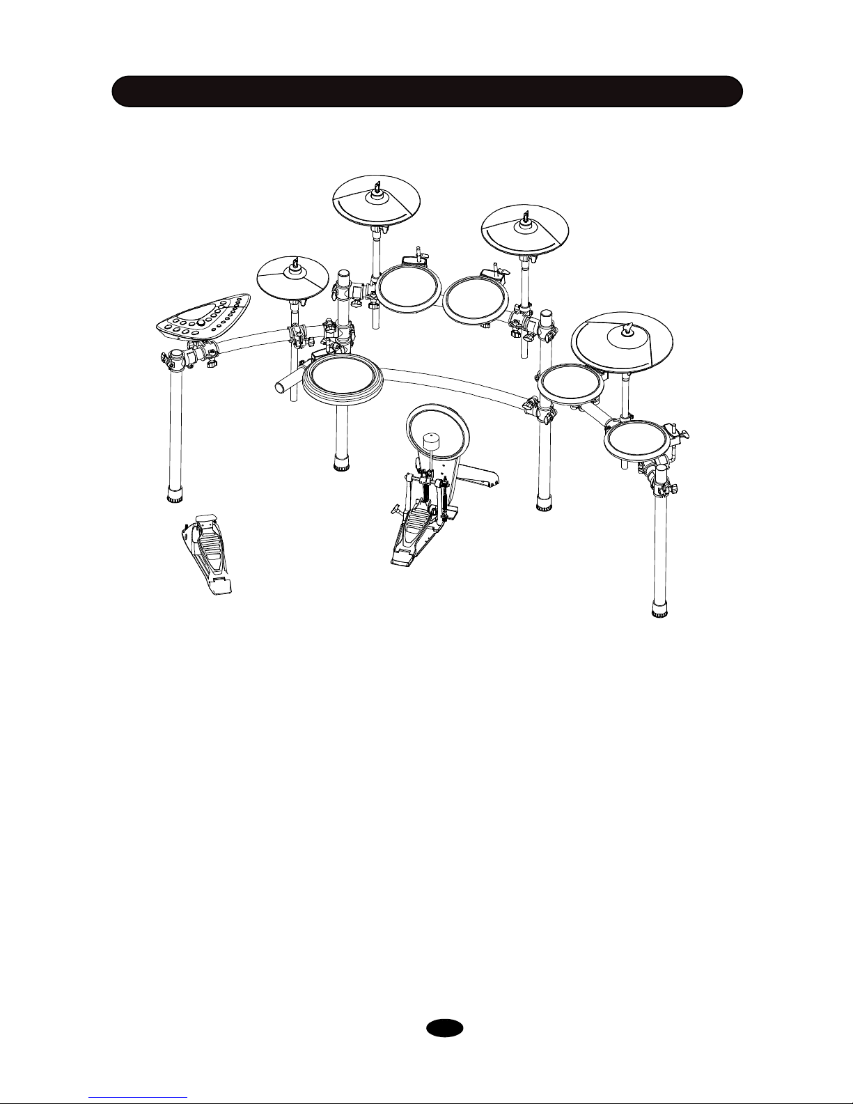
INSTALLATION
The diagram shows complete drum kit after installation.
Each drum pad, cymbal pad and Hi-Hat control pedal has its part number underneath the part name
for your reference in installation. The part number is printed in part packing box.
Power adaptor and connection cables are not shown in the diagram.
* KICK PEDAL IS OPTIONAL ACCESORY
CRASH1
B-12 Cymbal-edg
CRASH 2
B-12 Cymbal-edg
RIDE
B-14 Cymbal-edg-Bell
HI-HAT
A-8 Hi-Hat
TOM1
B-8 Tom
TOM2
B-8 Tom
TOM3
B-8 Tom
TOM4
B-8 Tom
SOUND MODULE
HD-010B
SNARE
B-8 Snare
HI-HAT CONTROL PEDAL
B-HH Ctrl
KICK
B-8 Kick
KICK PEDAL
P-6B Kick Pedal
RACK SYSTEM
RACK C
1
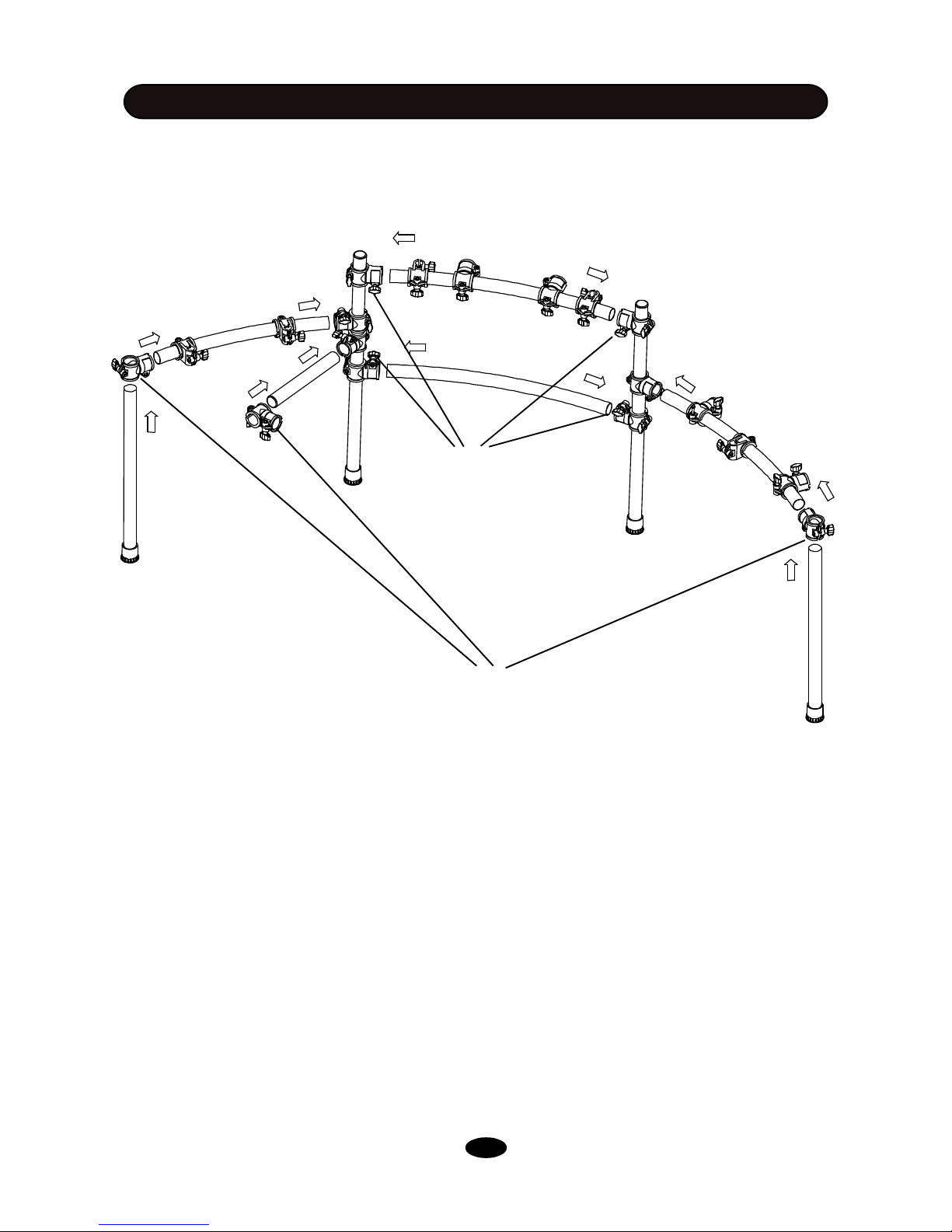
You can find all components in package.
All pipes with clamp kit attached are in RACK SYSTEM box, except right , left lag and snare arm
without clamp kit, which is in CLAMP box.
Take off all parts from package. Insert pipes into relevant clamp as shown in the daigram, fasten wing
nut to secure them.
INSTALLATION
These clamps are in the CLAMP box
Wing nut
RACK INSTALLATION - 1
2
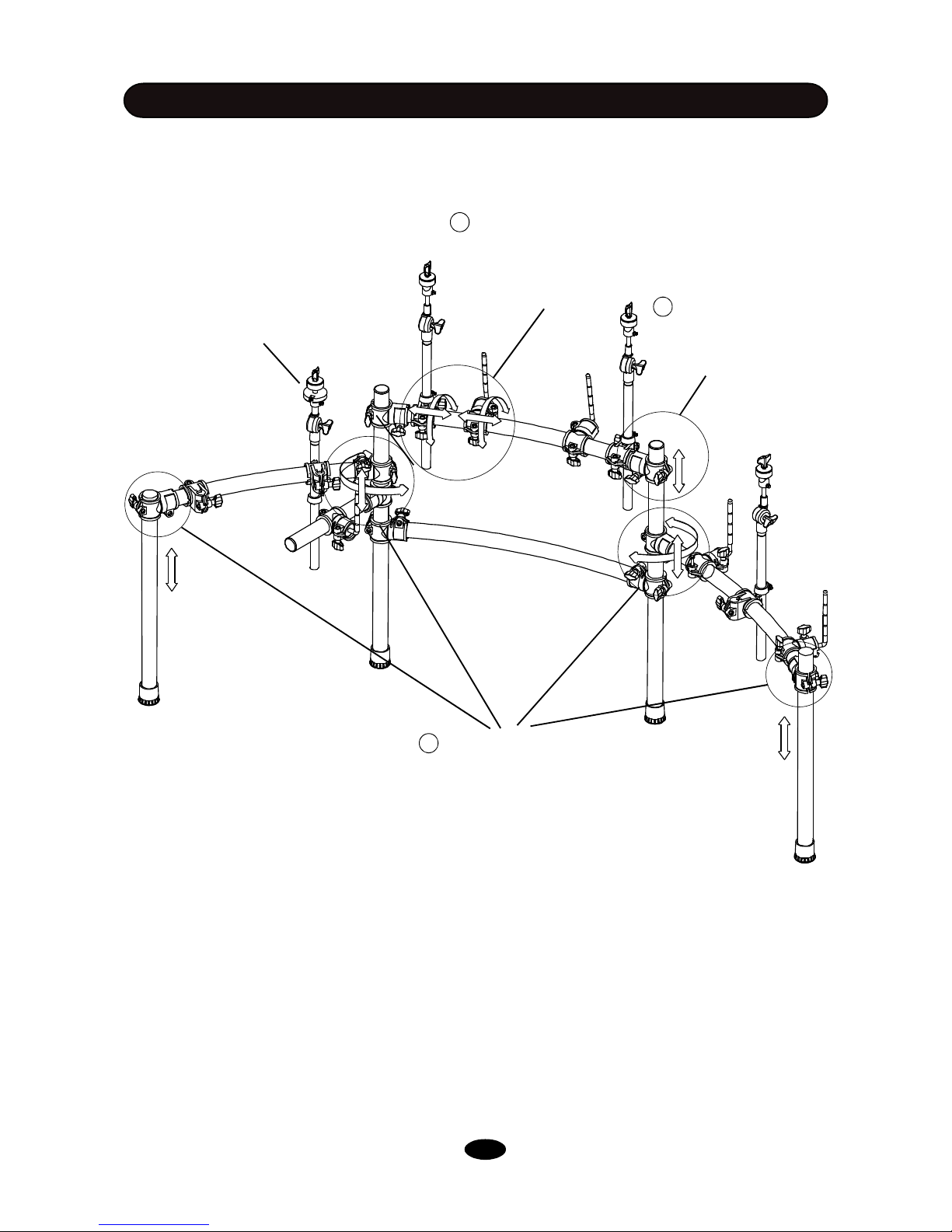
INSTALLATION
Please note: Hi-Hat rod is different
from ride/crash rod.
RACK INSTALLATION - 2
1 Loosen wing nuts in the clamp,
adjust the position of the arm and
legs, then tighten the wing nuts
2 Loosen wing nut in the
clamp. Move the cross
beam to proper location,
then tighten the wing nuts
3 Loosen wing nuts in
the clamp. Rotate the LRod and cymbal support
rod to proper position, then
tighten the wing nuts
Adjust arm, leg and cross beam to proper position. Insert L-rods and cymbal support rods into relevant clamp as shown in the diagram, then adjust their positions.
3
INSTALLATION
1. Align holes in the support and stand 2
then insert bolts and fasten with attached
2. Insert tongue 4 of the kick stand into slot of
the pedal
3. Align holes in the tongue and the pedal, then
insert bolts and fasten with attached key. .
1
Kick Installation
1. Align holes in the sound module and the model mount then insert
screws and fasten it.
2. Insert rod of the model mount into the clamp, then tighten the wing
nut.
Sound module Installation
Please refer to the SOUND MODULE Chapter for electronic connection.
Electronic Connection
P-6B
4
Finalizing the Installation
After install all components, fine adjust the arm, clamps and rods to
the best position you desire.
2
1
3
3
2
3
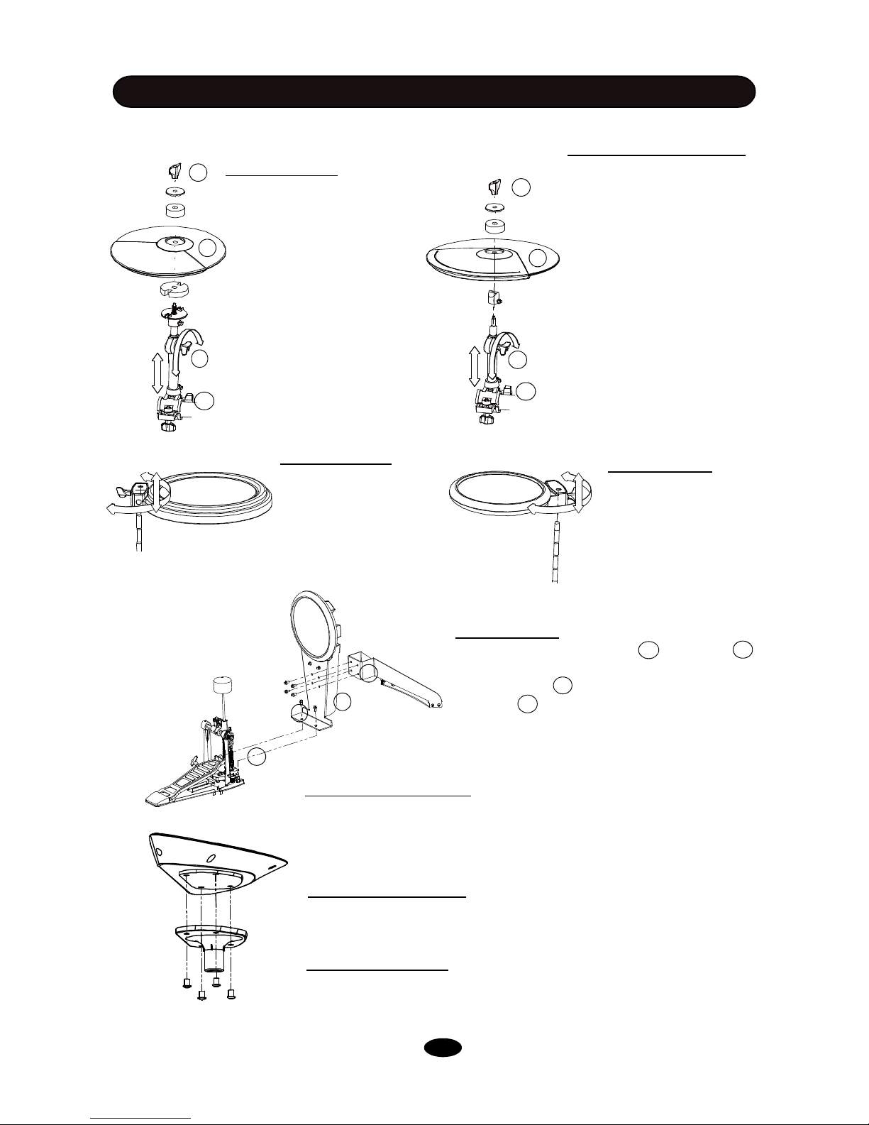
1
1. Remove the wing nut,
washer and felt pad from the
top of the rod.
3. Loosen the side wing nut,
adjust the angle of the rod
then re-tighten the wing nut.
1. Remove the wing nut,
washer and felt pad from the
top of the rod.
3. Loosen the side wing nut,
adjust the angle of the rod
then re-tighten the wing nut.
1. Loosen the wing nut,
place the snare on the
snare installation snare
L-Rod.
2. Put the Hi-Hat into the
rod, then place back parts
removed in the step 1. Retighten the wing nut.
2. Adjust the angle and height of the
snare pad then tighten the wing nut.
Hi-Hat Installation
Crash and Ride Installation
Snare Installation
1. Loosen the wing nut,
place the tom pad on
the installation L-Rod.
2. Adjust the angle and
height of the tom pad
then tighten the wing
nut.
Tom Installation
COMPONENTS INSTALLATION
2. Put the cymbal pad into the
rod, then place back parts removed in the stet 1. Fasten
the wing nut but not too tightly.
It allows the pad a little bit wobbling like real acoustic
cymbal.
4. Loosen the wing nut on the
clamp, adjust the height of the
rod then re-tighten the wing
nut.
4. Loosen the wing nut on the
clamp, adjust the height of
the rod then re-tighten the
wing nut.
4
2
1
3
4
4
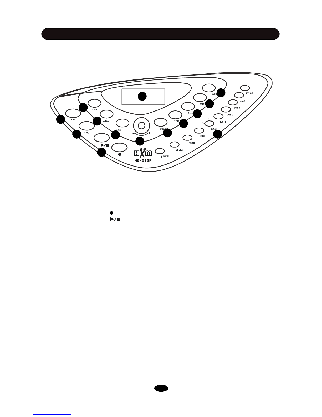
(1) LCD Display: Information display such as Kit number and name, Song name etc.
(2) KIT Button: Enter the Drum kit screen and select kit
(3) SONG Button: Enter the Song mode to play demo or User songs
(4) Sequencer Buttons: Record Button, Press it to enter the record window
Play/Stop Button
The Play/Stop button is used in both Song and Record operations. Please refer to relevant chapters for detailed information.
(5) COUNT Button: Enter the Count mode to test how fast you can strike
(6) CLICK Button: Metronome switch and edit
(7) TEMPO Button: Change metronome tempo
(8) DATA +/- Knob: Rotate the knob to change data for all operations. The knob is with push
switch, when push the knob down, the switch will be on. Press the knob down then rotate it to
adjust master volume in the Kit Selection and Song window. Pushing down the knob can function
as ENTER button.
(9) ENTER Button: Confirm your operating
(10) EXIT Button: Exit to the previous window or return to the Kit Selection window
(11) SETUP Button: Enter the Setup mode and set parameters
(12) EDIT Button: Enter the Kit Edit mode and edit parameters
(13) MODE Button: Change Demo playing mode
(14) Pad Select Buttons: Select a pad and its part for edit in the Edit mode. These are dual-
function buttons. In the Kit Select mode, they are used for kit quick selection.
SOUND MODULE
CONTROL PANEL
1
10
11
13
12
143
5
2
8
6
7
4
9
5
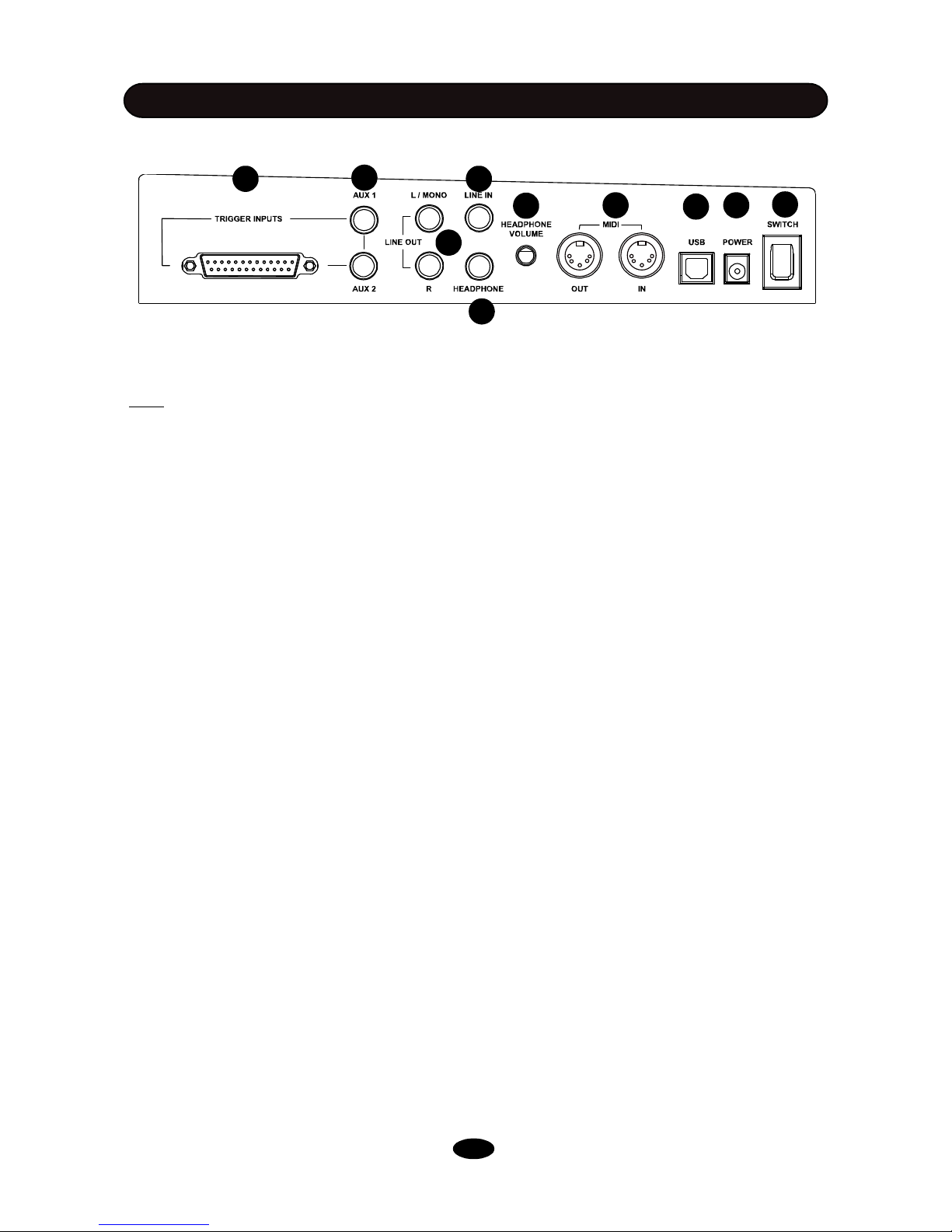
BACK PANEL
SOUND MODULE
1
2
3
4
6
7
8
5
9
10
(1) Power Switch: Turn On/Off the sound module
Note: When you turn the power off, do not turn it on immediately. Wait at least five seconds to turn
the power on so that the electronic circuits can properly reset.
(2) Power In Jack: Plug in the DC cable of the attached adaptor
(3) USB Jack: The USB connector allows you to connect the drum directly to your computer’s
USB port. The USB interface is compatible with Windows XP/Vista, Windows 7 and MAC. The
computer will recognize the drum as Audio Device. Please see the MIDI & USB chapter of this
manual for details
(4) MIDI Jack: MIDI jacks allow communication with other products equipped with MIDI
interfaces. Please see the MIDI & USB chapter of this manual for details
(5) Headphone Jack: The drum has stereo headphone jack. You can play in total silence without
disturbing others in the room by plugging a set of headphones into the jack.
(6) Headphone Volume Knob: Rotate it to adjust the headphone volume
(7) Line In Jack: Line In stereo audio input jack will mix the supplied signal with the internal drum
sound. It can be used to hook up items such as CD players, MP3 player etc.
(8) Line Out Jack: There is no built-in speaker in the drum. Line Out stereo audio output supplies
the drum output signal to external amplification, such as home stereo, PA system or other stand
alone amplifiers. If you connect with external mono system, use L/MONO output and stereo/mono
adapter is recommended.
(9) Pad Trigger Connector: Each pad and Hi-Hat control pedal has labeled cable. All cables are
merged into a single connector. Plug in the cable into jack of corresponding component, Then, plug in
the connector here.
(10) Expanded Pad Trigger Jack: Plug in the cable of the Tom4 into the AUX1 and the Ride into the
AUX2.
6
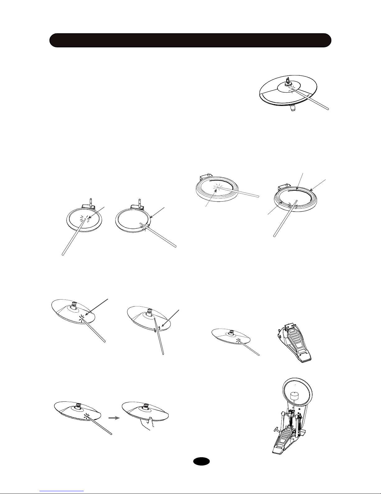
Playing Cymbal Bell
Strike the bell at the large ride cymbal make
symbal bell sound.
PLAYIN PAD
TURN ON THE POWER
(1) Adjust volume of external audio device
connected with the drum to lower level.
(2) Press the POWER button while don’t strike
pad or press the Hi-Hat control pedal.
(3) Turn on external devices connected.
(4) Strike pad and adjust the volume to proper
level.
PLAYING PADS
Playing Snare Drum
Strike the central position (head) of the pad to
make head sound, strike the rim of the pad to
make rim sound. There are two rim portions with
different rim sound. Also, there is a mark on the
pad to indicate the portion.
Playing Cymbal
Strike the central position (bow) of the cymbal
to make cymbal bow sound, strike the edge of
the cymbal to make edge shot sound.
Cymbal Choke
Strike a cymbal, its sound will sustain. Then
squeeze the edge portion to mute the sound.
Please note that the Hi-Hat has no choke
feature.
Bow
All pads have striking force sensitivity feature.
Strike the pad harder to make higher volume
and strike the pad softer to make lower
volume.
Playing Tom Drum
Strike the central position (head) of the pad to
make head sound, strike the rim of the pad to
make rim sound.
Playing Kick Drum
Press the Kick drum pedal to make kick
drum sound.
Head
Ri
m2
Rim1
MarkHead
Rim
Edge
Playing Hi-Hat
(1) Strike the Hi-Hat pad without pressing the HiHat control pedal to make open Hi-Hat sound.
(2) Strike the Hi-Hat pad with fully pressing the
Hi-Hat control pedal to make close Hi-Hat sound.
(3) Strike the Hi-Hat pad while pressing the HiHat control pedal gradually to make consecutive
open to close Hi-Hat sound.
(4) Press the Hi-Hat pedal down quickly to make
Hi-Hat pedal sound.
7
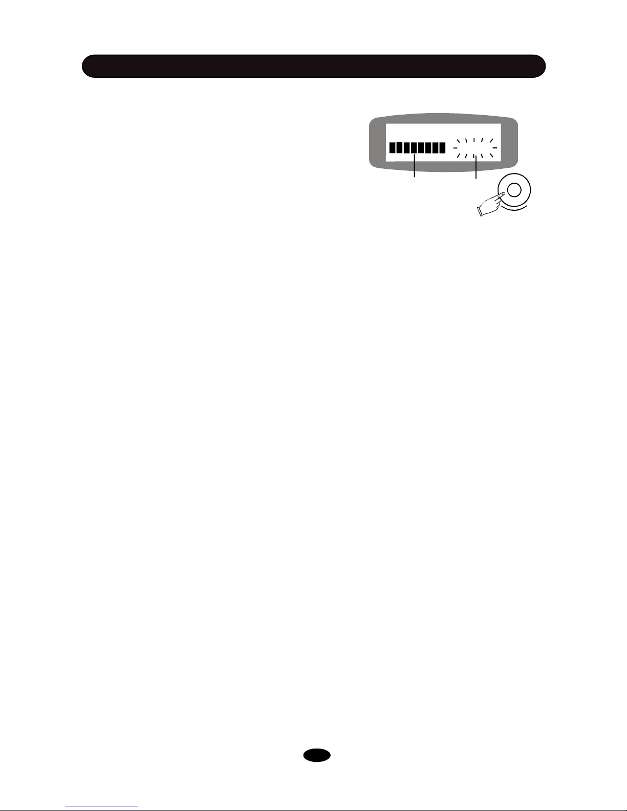
VOLUME CONTROL
MASTER VOLUME
In the Kit and Song window, push the DATA knob to
enter the Master Volume control window. The current
volume level will be blinking. Rotate the DATA knob to
change the master volume ranged 0 - 127. Press the
EXIT button, or after about 5 seconds without any
adjustment, it will return to the previous window.
HEADPHONE VOLUME
Adjust the headpnone volume by rotating the HEADPHONE VOLUME knob in the back panel.
Master Volume
115
Master volumeVolume indicator
+
8
 Loading...