

HXM HD-008 User Manual

HD-008 DIGITAL DRUM
USER’S MANUAL

CAUTION
Any changes or modifications in construction of this device which are not expressly approved by
the party responsible for compliance could void the user’s authority to operate the equipment.
WARNING
When using electrical products, basic safety precautions should always be followed, including the
following:
NOTE: This equipment has been tested and found to comply with the limits for a Class B digital
device, pursuant to Part 15 of the FCC Rules.
Also, this equipment has been tested and found to comply with the limits for following standard:
EN55022-2006
EN55024:1998/+A1:2001/+A2:2003
EN55013:2001/+A1:2003/+A3:2006
EN55020:2007
EN61000-3-2:2006
EN61000-3-3:1995/+A1:2001/+A2:2003
These limits are designed to provide reasonable protection against harmful interference in a residential installation. This equipment generates, uses, and can radiate radio frequency energy and, if
not installed and used in accordance with the instructions, may cause harmful interference to radio
communications. However, there is no guarantee that interference will not occur in a particular
installation. If this equipment does cause harmful interference to radio or television reception, which
can be determined by turning the equipment off and on, the user is encouraged to try to correct the
interference by one or more of the following measures:
- Reorient or relocate the receiving antenna.
- Increase the separation between the equipment and receiver.
- Connect the equipment into an outlet on a circuit different from that to which the receiver is
connected.
- Consult the dealer or an experienced radio/TV technician for help.
CAUTION

TAKING CARE OF YOUR DRUM
- direct sunlight (near a window),
- high temperatures (near a heat source,
outside, or in a car during the daytime),
- rain or excessive humidity,
- excessive dust,
- strong vibration.
w The unit shall not be exposed to dripping or
splashing and no objects filled with liquids,
such as vases, shall be placed on the unit.
w The drum contains digital circuitry and may
cause interference if placed too close to
radio or television receivers. If interference
occurs, move the drum further away from
the affected equipment.
POWER
w Only use attached power adaptor.
w Turn the power switch off when the drum is
not in use.
w To avoid damage to the drum and other
devices to which it is connected, turn the
power switches of all related devices off
prior to connection or disconnection of
audio cables.
w Turn the power off if the main cable of the
adaptor is damaged or the instrument is
spattered with liquid.
w Do not switch the unit on and off in quick
succession, this places an undue load on
the electronic components.
w Unplug the AC power cord during an electri-
cal storm.
w Avoid plugging the AC adaptor into the same
AC outlet as appliances with high power
consumption, such as electric heaters or
ovens.
SERVICE AND MODIFICATION
This product should be serviced by qualified
service personnel when,
w the power supply cord or the plug of the
adaptor has been damaged,
w liquid has been spattered into the unit or it has
been exposed to rain,
w the instrument does not appear to operate
normally or exhibits a marked change in
performance,
w the instrument has been dropped or the
cabinet has been damaged.
HANDLING AND TRANSPORT
w Never apply excessive force to the controls,
connectors, pads or other parts of the
instrument.
w Always unplug cables by gripping the plug
firmly, not by pulling on the cable.
w Physical shocks caused by dropping,
bumping, or placing heavy objects on the
instrument can result in scratches and/or
more serious damage.
w Carefully check the amplifier volume control
before stating to play. Excessive volume can
cause permanent hearing loss.
CLEANING
w Clean the unit with a dry or light-wet soft cloth.
Do not use paint thinner or petrochemical
based polishes.
LOCATION
w Do not expose the drum to the following
conditions to avoid deformation, discoloration,
or more serious damage,
DO NOT ATTEMPT TO OPEN THE UNIT OR MAKE ANY CHANGE IN THE CIRCUITS OR
PARTS OF THE UNIT.
!

CONFIGURATION ................1
INSTALLATION ................2
KITA..............................2
KIT B........................5
SOUND MODULE ....................10
Control Panel .....................10
Back Panel ........................11
PLAYING PAD ..................12
DRUM KIT .........................13
SONG .......................14
Demo Song ......................14
User Song .................15
METRONOME ........................16
Metronome ............................16
Tempo .....................17
DRUM KIT EDIT ...................18
Select kit for editing ..............18
Enter the Edit Mode .................19
Select part to edit .................20
Select parameter to edit ..........20
Edit the parameter ..............20
Edit another parameter or part ....20
Complete the edit .................21
STRIKING COUNT ..................22
SETUP .........................23
Accompaniment Volume for Demo .....23
Percussion Volume for Demo ...23
Master Tune ......................24
Count Sesitivity .....24
Equalizer .................24
Advanced Parameter Edit .........25
Sesitivity .......................25
Dynamic Range .................26
Trigger Corve .....................26
Cross Talk .......................26
Hi-Hat Pedal setting .........27
Reset ...........................29
RECORD ...........................30
Record ..........................30
Play back User Song ...............30
Erase User Song ..................31
MIDI & USB ......................32
KIT LIST ......................33
VOICE LIST .........................34
SPECIFICATIONS ..................38
CONTENTS TABLE
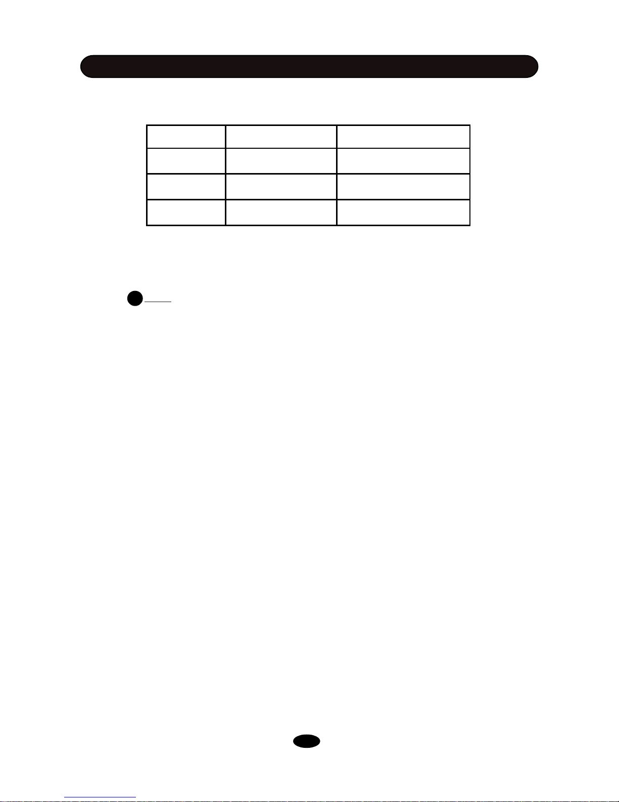
CONFIGURATION
This electronic drum kit has two optional configurations. The sound module is the same, the rack/
pad system has two types. The table below lists the differences between Kit A and Kit B.
KIT A KIT B
Tom Without rim With rim
Ride Without edge With edge
Rack System Smaller Larger
!
Tom pad in Kit B has rim shot feature, but Kit A not.
Ride cymbal in Kit B has edge strike and choke features, but Kit A not.
This manual is universal for both Kit A and Kit B. Some contents are for Kit B only. They are indicated by “ Note:” ,
Please read carefully to suit your Kit.
The installation of Kit A and Kit B is different. Please read the next chapter for details.
1
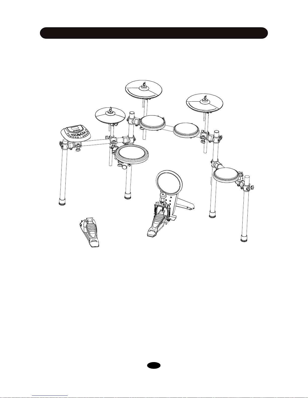
INSTALLATION
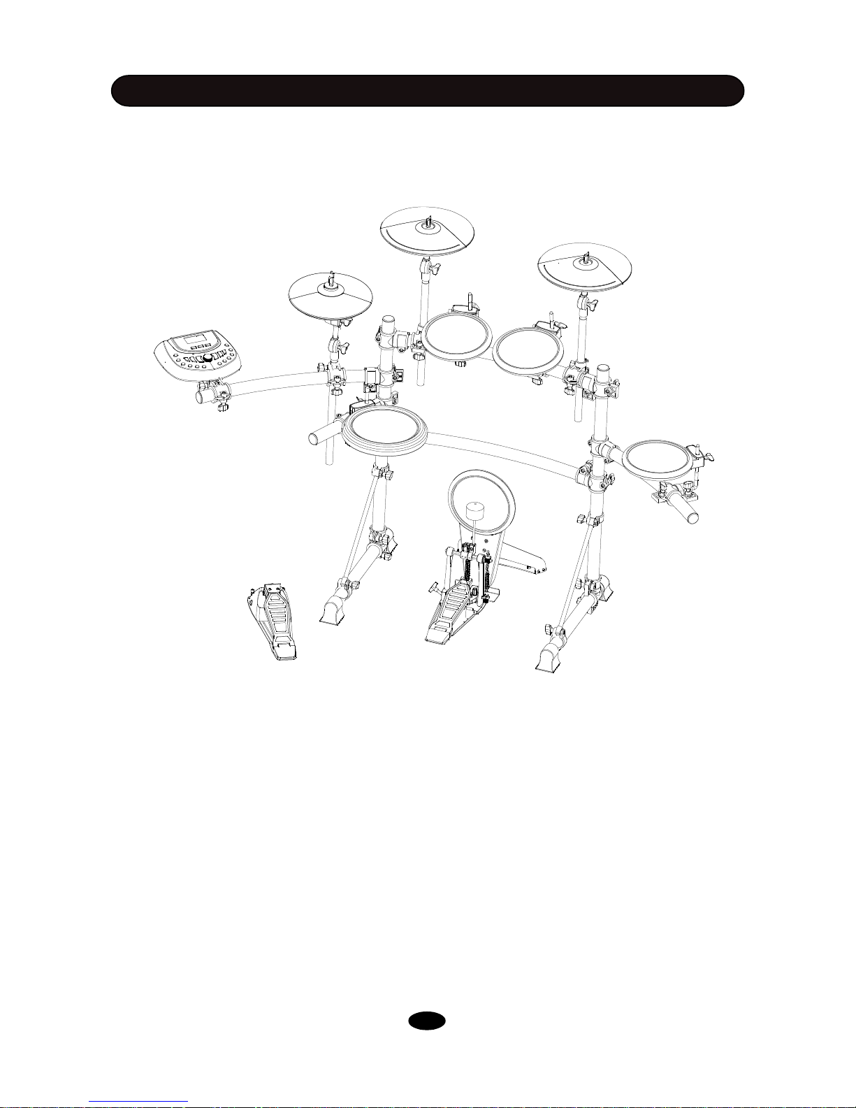
The drawing shows complete drum kit after your installation.
Each drum pad, cymbal pad and Hi-Hat control pedal has its part number underneath the part name
for your reference in installation. The part number is printed in part packing box.
Power adaptor and connection cables are not shown in the drawing.
KIT A
SOUND MODULE
CRASH
KICK
SNARE
TOM 2
TOM 1
HI-HAT
TOM 3
RIDE
KICK PEDAL
HI-HAT CONTROLLER
B-8 Snare
HD-008
A-12 Cymbal-edg
B-8 Kick
B-HH Ctrl
P-6C Kick pedal
A-8Tom
A-8Tom
A-8Tom
A-8 Hi-Hat
A-12 Cymbal
* KICK PEDAL IS OPTIONALACCESORY
RACK SYSTEM
RACKA
2

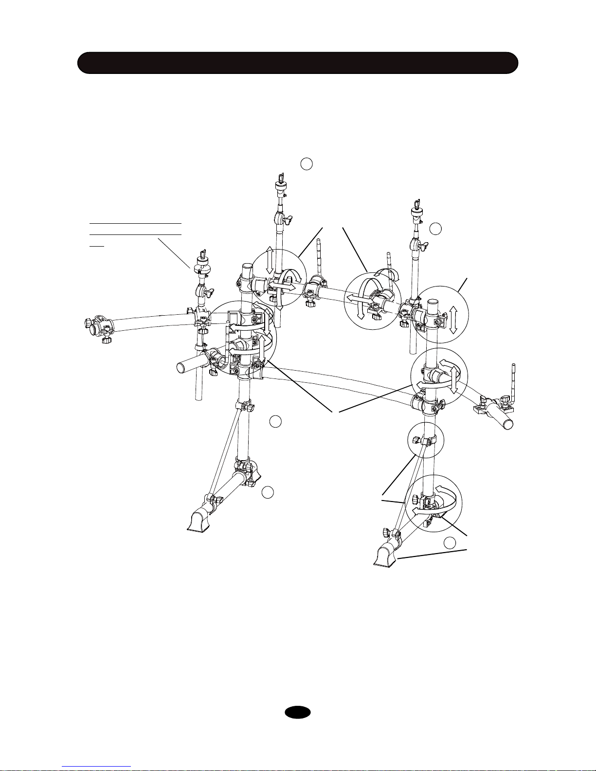
INSTALLATION
Rack clamp
L-Rod
Arm
Leg clamp
Wing nuts
Pad clamp
Crash and Ride rod
Leg
Hi-Hat rod
Rack System
RACKA
KIT A
RACK SYSTEM
You can find all of these components in RACK SYSTEM RACKA package.
Note: Please note that the Hi-Hat control pedal is also packaged in this box.
Folded rack in package
3
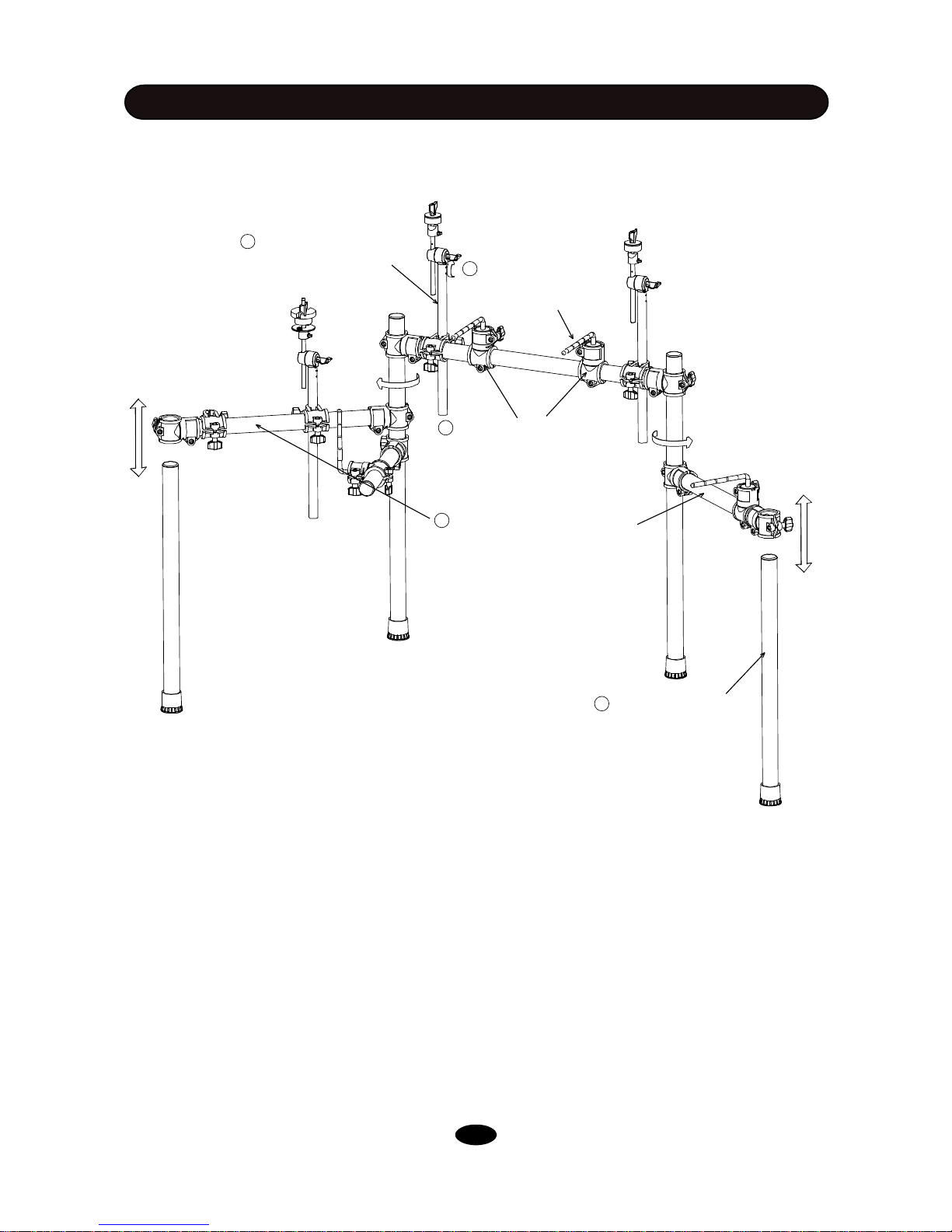
INSTALLATION
1. Loosen the wing nuts in the arm clamps. Open the arm, adjust the position, then tighten the wing
nuts
2. Loosen the wing nuts in the leg clamp. Insert the left and right leg into the clamp, adjust the height to
touch floor firmly, then tighten the wing nuts.
3. Loosen the wing nuts in the clamp. Move the pad clamps to proper location, then tighten the wing
nuts
4. Loosen the wing nuts in the clamp. Rotate the pad installation L-Rod to proper position, and then
tighten the wing nuts
5. Loosen the wing nuts in the clamp. Insert the cymbal installation rod to proper location, and then
tighten the wing nuts
1 Open the arm, adjust the position,
then tighten the wing nuts
2 Install the left and right leg,
adjust the height to touch
floor firmly, then tighten the
wing nuts.
4 Rotate the pad installation
L-Rod to proper position, then
tighten the wing nuts
3 Move the pad clamps to proper
location, then tighten the wing nuts
5 Insert the cymbal installation
rod to proper location, then
tighten the wing nuts
KIT A
RACK INSTALLATION
4
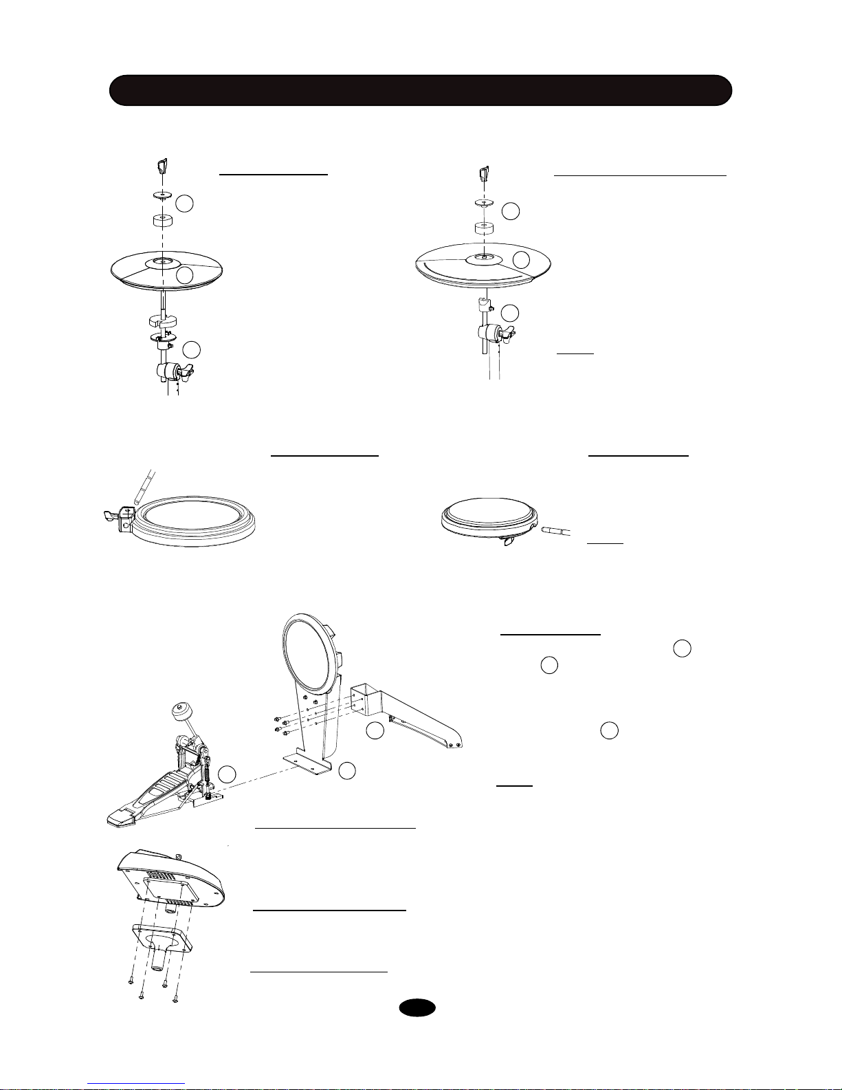
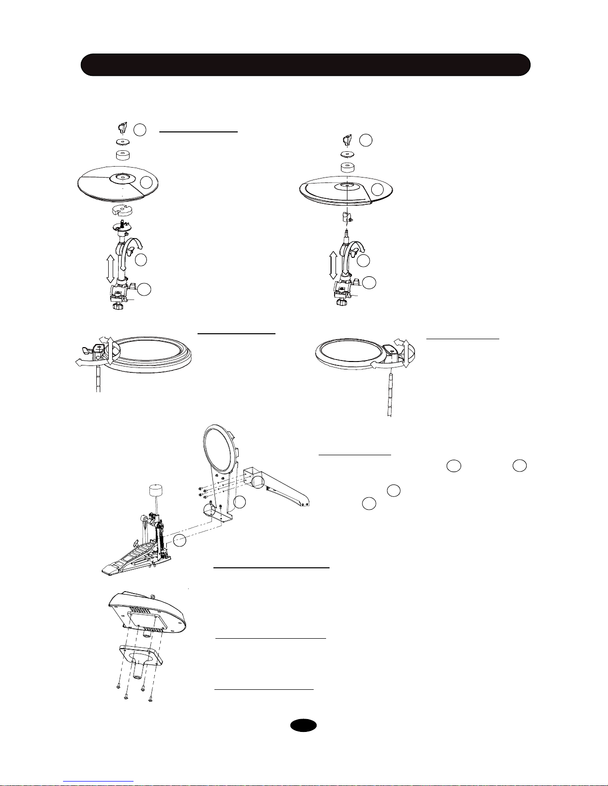
INSTALLATION
1. Remove the wing nut,
washer and felt pad
3.Adjust the angle and
height of the rod then
tighten the wing nut.
1. Remove the wing nut,
washer and felt pad
2. Put the cymbal pad into the
rod, then attach parts removed in the stet 1. Fasten
the wing nut but not too
tightly. It allows the pad a little
bit wobbling like real acoustic cymbal.
Note: Crash and Ride has
different part number. Please
refer to indication in the page
2.
3.Adjust the angle of the rod then tighten the wing nut.
1. Insert the snare into
the snare installation LRod, then tighten the
wing nut.
2. Put the Hi-Hat into the
rod, then attach parts removed in the stet 1. Fasten the wing nut.
2. Adjust the angle of
the L-Rod then tighten
the wing nut.
Hi-Hat Installation
Crash and Ride Installation
Snare Installation
1. Insert the tom into
the tom installation LRod, then tighten the
wing nut.
Note: All toms use the
same pad.
2. Adjust the angle of the L-Rod then
tighten the wing nut.
Tom Installation
1. Align holes in support and
stand then insert bolts and fasten
with attached key.
2. Insert tongue of the kick stand into
slot of the pedal . Tighten the wing
nut on the pedal level to fix it.
Note: Please refer to page 9 for pedal
P-6C installation.
Kick Installation
KIT A
COMPONENTS INSTALLATION
1. Align holes in supporting board and sound module then insert screws and
fasten it.
2. Insert rod of the supporting board to the clamp, then tighten the wing nut.
Sound module Installation
Please refer to the SOUND MODULE Chapter for electronic connection.
Electronic Connection
P-6C
Finalizing the Installation
After install all components, fine adjust the arm, clamps and rods to the best
positionyou like finally.
5
2
1
3
2
1
3
2
1
3
2
1
3
INSTALLATION
KIT B
The drawing shows complete drum kit after your installation.
Each drum pad, cymbal pad and Hi-Hat control pedal has its part number underneath the part name
for your reference in installation. The part number is printed in part packing box.
Power adaptor and connection cables are not shown in the drawing.
CRASH
B-12 Cymbal-edg
RIDE
B-12 Cymbal
KICK PEDAL
P-6B Kick pedal
HI-HAT CONTROL PEDAL
B-HH ctrl
KICK
B-8 Kick
SNARE
B-8 Snare
RACK SYSTEM
RACKB
TOM1
B-8 Tom
Hi-HAT
A-8 Hi-Hat
SOUND MODULE
HD-008
TOM3
B-8 Tom
TOM2
B-8 Tom
* KICK PEDAL IS OPTIONAL ACCESORY
6

Folded rack in package
Rubber Feet
INSTALLATION
KIT B
L-Rod Clamp Wing nut
Arm
Arm
Leg
Rack System
RACKB
Crash support rod Ride supprt rod
Hi-Hat support rod
RACK SYSTEM
You can find all of these components in RACK SYSTEM RACKB package.
7
INSTALLATION
KIT B
RACK INSTALLATION
8
4 Loosen wing nut in
the clamp. Move the
cross beam to proper
location, then tighten
the wing nuts
5 Loosen the wing nuts in
the clamp. Move and rotate the L-Rod and cym-
bal support rod to proper
position, and then tighten
the wing nuts
3 Loosen the wing nuts in the arm
clamp. Open arms, adjust the
position, then tighten the wing nuts
1 Loosen the wing nuts in the
leg clamp.Open the legs, adjust the position, then tighten
the wing nuts
2 Insert the feet
Please note: Hi-Hat rod is
different from ride/crash
rod.
Adjust arm, leg and cross beam to proper position. Place L-rods and cymbal support rods on relevant
clamp as shown in the diagram.
KIT B
INSTALLATION
COMPONENTS INSTALLATION
9
1. Align holes in the support and stand 2
then insert bolts and fasten with attached key.
2. Insert tongue 4 of the kick stand into slot of
the pedal
3. Align holes in the tongue and the pedal, then
insert bolts and fasten with attached key. .
1
2
3
1
1. Remove the wing nut,
washer and felt pad from the
top of the rod.
3. Loosen the side wing nut,
adjust the angle of the rod
then re-tighten the wing nut.
1. Remove the wing nut,
washer and felt pad from the
top of the rod.
3. Loosen the side wing nut,
adjust the angle of the rod
then re-tighten the wing nut.
1. Loosen the wing nut,
place the snare on the
snare installation snare
L-Rod.
2. Put the Hi-Hat into the
rod, then place back parts
removed in the step 1. Retighten the wing nut.
2. Adjust the angle and height of the
snare pad then tighten the wing nut.
Hi-Hat Installation
Snare Installation
1. Loosen the wing nut,
place the tom pad on
the installation L-Rod.
2. Adjust the angle and
height of the tom pad
then tighten the wing
nut.
Tom Installation
Kick Installation
1. Align holes in the sound module and the model mount then insert
screws and fasten it.
2. Insert rod of the model mount into the clamp, then tighten the wing
nut.
Sound module Install ation
Please refer to the SOUND MODULE Chapter for electronic connection.
Electronic Connection
P-6B
4
Finalizing the Installation
After install all components, fine adjust the arm, clamps and rods to
the best position you desire.
2
1
3
2. Put the cymbal pad into the
rod, then place back parts removed in the stet 1. Fasten
the wing nut but not too tightly.
It allows the pad a little bit wobbling like real acoustic
cymbal.
3
4. Loosen the wing nut on the
clamp, adjust the height of the
rod then re-tighten the wing
nut.
4. Loosen the wing nut on the
clamp, adjust the height of
the rod then re-tighten the
wing nut.
4
2
1
3
4
 Loading...