

Page 1
R
H
CORPORATION
W
H
OPERATOR’S MANUAL
HWH TOUCH PANEL-CONTROLLED
LEVELING SYSTEM
310 SERIES
SPACEMAKER ROOM EXTENSION SYSTEM
FEATURING:
TOUCH PANEL LEVELING CONTROL
HYDRAULIC LEVELING
AUTOMATIC SUSPENSION AIR DUMP
STRAIGHT-ACTING JACKS
DUAL CYLINDER ROOM EXTENSION
DUAL CYLINDER GENERATOR SLIDE
DUAL CYLINDER ENGINE ACCESS DOOR
HWH HYDRAULIC LEVELING
ON
NOT IN
PARK/
STORE
UNDERSTAND OPERATOR’S MANUAL BEFORE USING. BLOCK FRAME AND TIRES
DUMP
OFF
SECURELY BEFORE REMOVING TIRES OR CRAWLING UNDER VEHICLE.
BRAKE
CAUTION!
HWH CORPORATION
(800) 321-3494 / (563) 724-3396
INTERNET: http: //www.hwhcorp.com
(ON I-80, EXIT 267 SOUTH)
2096 MOSCOW ROAD
MOSCOW, IOWA 52760
ML16951/MP05.3212
21MAR01
Page 2
OPERATOR’S MANUAL
CAUTION !
READ THE ENTIRE OPERATOR’S MANUAL BEFORE OPERATING.
BLOCK FRAME AND TIRES SECURELY BEFORE CRAWLING UNDER VEHICLE. DO NOT USE LEVELING JACKS
OR AIR SUSPENSION TO SUPPORT VEHICLE WHILE UNDER VEHICLE OR CHANGING TIRES. VEHICLE MAY
DROP AND OR MOVE FORWARD OR BACKWARD WITHOUT WARNING CAUSING INJURY OR DEATH.
KEEP ALL PEOPLE CLEAR OF THE VEHICLE WHILE LEVELING SYSTEM AND ROOM EXTENSIONS ARE
BEING OPERATED.
KICK-DOWN JACKS MAY ABRUPTLY SWING UP WHEN THE FOOT OF THE JACK CLEARS THE GROUND
OR WHEN THE JACK REACHES FULL EXTENSION.
NEVER PLACE HANDS OR OTHER PARTS OF THE BODY NEAR HYDRAULIC LEAKS. OIL MAY PENETRATE
THE SKIN CAUSING INJURY OR DEATH.
WEAR SAFETY GLASSES WHEN INSPECTING OR SERVICING THE SYSTEM TO PROTECT EYES FROM DIRT,
METAL CHIPS, OIL LEAKS, ETC. FOLLOW ALL OTHER APPLICABLE SHOP SAFETY PRACTICES.
IF THE VEHICLE IS EQUIPPED WITH KICK-DOWN STYLE JACKS, DO NOT OVER EXTEND THE REAR JACKS.
IF THE WEIGHT OF THE VEHICLE IS REMOVED FROM ONE OR BOTH REAR WHEELS, THE VEHICLE MAY
ROLL FORWARD OR BACKWARD OFF OF THE JACKS.
NOTE: KEEP THE CONTROL VALVE LEVERS IN THE STORE POSITION WHEN JACKS ARE NOT IN USE.
IMPORTANT: IF VEHICLE IS EQUIPPED WITH A ROOM EXTENSION, READ ROOM EXTENSION SECTION
BEFORE OPERATING LEVELING SYSTEM.
HOW TO OBTAIN WARRANTY SERVICE
THIS IS NOT TO BE INTERPRETED AS A STATEMENT OF WARRANTY
HWH CORPORATION strives to maintain the highest level of
customer satisfaction. Therefore, if you discover a defect or
problem, please do the following:
FIRST:
vehicle or had the leveling system installed. Dealership
management people are in the best position to resolve
the problem quickly. If the dealer has difficulty solving
the problem, he should immediately contact the Customer
Service Department, at HWH CORPORATION.
SECOND:
notify the Customer Service Department:
HWH CORPORATION 2096 Moscow Rd. Moscow IA. 52760
(563) 724-3396 OR (800) 321-3494. Give your name and
address, coach manufacturer and model year, date the
coach was purchased, or the date of system installation,
Notify the dealership where you purchased the
If your dealer cannot or will not solve the problem,
description of the problem, and where you can be reached
during business hours (8:00 a.m. till 5:00 p.m. c.s.t.).
HWH CORPORATION personnel will contact you to
determine whether or not your claim is valid. If it is, HWH
CORPORATION will authorize repair or replacement of the
defective part, either by appointment at the factory or by the
authorization of an independent service facility, to be
determined by HWH CORPORATION. All warranty repairs
must be performed by an independent service facility
authorized by HWH CORPORATION, or at the
HWH CORPORATION factory, unless prior written approval
has been obtained from proper HWH CORPORATION
personnel.
MP15.0
30MAY01
Page 3
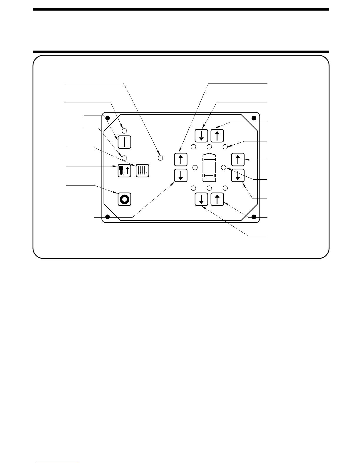
CONTROL IDENTIFICATION
"NOT IN PARK"
LIGHT
POWER ON
LIGHT
"ON" BUTTON
STORE LIGHT
"DUMP"
BUTTON
"STORE"
BUTTON
"OFF"
BUTTON
LEFT SIDE
RETRACT BUTTON
HWH HYDRAULIC LEVELING
ON
NOT IN
PARK/
BRAKE
STORE
UNDERSTAND OPERATOR’S MANUAL BEFORE USING. BLOCK FRAME AND TIRES
DUMP
OFF
SECURELY BEFORE REMOVING TIRES OR CRAWLING UNDER VEHICLE.
CAUTION!
LEFT EXTEND
BUTTON
FRONT RETRACT
BUTTON
FRONT EXTEND
BUTTON
WARNING LIGHTS
(4-Red)
RIGHT SIDE
EXTEND BUTTON
LEVELING LIGHTS
(4-Yellow)
RIGHT SIDE
RETRACT BUTTON
REAR EXTEND
BUTTON
REAR RETRACT
BUTTON
CONTROL BUTTONS INDICATOR LIGHTS
"ON" BUTTON :
system. It provides control power to operate the electrical
relay on the pump, the leveling lights and the 4 red warning
lights.
"OFF" BUTTON :
leveling system.
"STORE" BUTTON :
the same time.
EXTEND BUTTONS (UP ARROWS) :
extend their respective jack pairs to lift the vehicle.
RETRACT BUTTONS (DOWN ARROWS) :
will retract their respective jack pairs to lower the vehicle.
"DUMP BUTTON" :
exhausted from the vehicle suspension while this button is
is being pushed. It will only work with the system on.
This is the "ON" button for the leveling
This button turns off control power to the
This button will retract all four jacks at
This is a momentary button. Air will be
CONTROL FUNCTIONS
POWER ON LIGHT :
STORE INDICATOR LIGHT : This light will be on when the
system is in the store mode.
NOT IN PARK/BRAKE LIGHT :
when the panel is on, but the hand/auto park brake is not set.
LEVELING LIGHTS :
that indicates a side or end of the vehicle is low. Extend the
appropriate jack pairs to put out the yellow light. Only one
These buttons will
These buttons
yellow leveling light can be on at a time. The vehicle is level
when all yellow lights are out.
"WARNING LIGHTS" :
when-ever the corresponding jack is extended 2 inches or
more, provided the ignition switch is in the "ACC" or "ON"
position and the system is on. Some vehicles are equipped
with a dash mounted master "JACKS DOWN" light which will
be on when one or more jacks are extended 2 or more
inches, provided the ignition switch is "ON".
extended 2 inches or more and the ignition switch is in the
"ON" position.
This light indicates the system is on.
This indicator light is on
If a yellow LEVELING LIGHT is on,
A red "WARNING" light will be on
A buzzer will sound if a jack is "WARNING BUZZER" :
MP25.17
19FEB01
Page 4

OPERATING PROCEDURES
SITE SELECTION
Park with the front of the vehicle facing downhill if possible.
Care must be taken not to raise the rear of the vehicle too high or
the vehicle may roll forward or backward off the jacks. If parking
ROOM EXTENSION AND GENERATOR SLIDE PROCEDURES
IMPORTANT:
sion and a generator slide. Read this section carefully.
Do NOT operate any room extension until the leveling and
stabilizing procedure is complete. Do NOT retract the leveling system until all room extensions are retracted. Do NOT
operate the leveling system when any room extensions are
extended.
This vehicle is equipped with a room exten-
ENGINE ACCESS DOOR OPERATION
The ENGINE ACCESS DOOR CONTROL SWITCH will operate with the leveling system on or off. The ignition key may be on
or off. The coach can be traveling when the ACCESS DOOR is
opened.
Push the ENGINE ACCESS DOOR CONTROL SWITCH to
open or close the ACCESS DOOR.
on soft ground or asphalt paving, wood blocks or pads should
be placed under the jacks.
Refer to the vehicle owners manual for proper operation of
room extensions or generator slide.
IMPORTANT:
vehicle is supported by the leveling system.
IMPORTANT:
open or close position for more than ten seconds after the door
is fully opened or closed.
NOTE:
ation of the door.
Do not use a room extension support when the
DO NOT hold the CONTROL SWITCH in the
Releasing the CONTROL SWITCH will halt the oper-
1. Place gear selector in the parking position, apply park brake
and block tires securely.
NOTE :
PARK/BRAKE" light will come on when the "ON" button is
pushed. The panel will turn on, but the system will not operate.
2. Place the ignition switch in the "ACC." position. The vehicle’s
engine must be off. Running the engine during or after leveling
may inflate the air suspension, lifting the vehicle out of level.
3. Push the "ON" button on the touch panel. The POWER ON
light will be lit. Place pads under the jacks, if necessary, at
this time.
4. Push and hold the "DUMP" button until all air is exhausted
from the vehicles suspension system.
5. A lit yellow LEVEL light indicates that the end, side, or corner is low. Push the EXTEND (up arrow) button to extend jack
pairs according to a lit yellow light. ALWAYS LEVEL THE VE-
If the hand/auto park brake is not set, the "NOT IN
LEVELING PROCEDURE
HICLE FROM SIDE TO SIDE BEFORE LEVELING THE VE-
HICLE FROM FRONT TO REAR. Only one yellow LEVEL light
can be on at one time. Extend jack pairs accordingly until all
yellow lights are out. If the ground is too uneven, the jack may
not have enough stroke to level the vehicle. The vehicle may
have to be moved.
6. After the vehicle is level, the jacks not used for leveling may be
extended until they touch the ground. This provides additional
stability against wind and activity in the vehicle. Do this by pushing
the front and/or rear EXTEND buttons as needed to extend any
remaining jacks. Do not use the right or left EXTEND buttons.
7. Push the "OFF" button on the touch panel.
8. Turn the ignition switch off.
MP35.3212
20NOV07
Page 5

OPERATING PROCEDURES
ROOM AND GENERATOR SLIDE EXTEND PROCEDURE
CAUTION:
ATOR SLIDE WITH ANY ROOM-LOCKING DEVICES LOCKED OR THE MANUAL-RETRACT WINCH ATTACHED CAN
CAUSE PERSONAL INJURY AND VEHICLE DAMAGE. IT
IS THE OPERATOR’S RESPONSIBILITY TO ENSURE THAT
ALL ROOM-LOCKING DEVICES AND THE MANUAL-RETRACT
WINCH ARE DISENGAGED BEFORE OPERATING THE ROOM.
IMPORTANT:
be leveled using the hydraulic leveling system before the room
or generator slide can be extended or retracted.
1. Follow the LEVELING AND STABILIZING PROCEDURE.
2. Unlock all room-locking devices.
NOTE:
room remove it before extending the room.
If the MANUAL RETRACT WINCH is attached to the
CAUTION:
CLEAR OF ROOM AND GENERATOR SLIDE WHEN OPERATING.
NOTE:
the room or generator slide.
3. Turn the ignition switch to "ACCESSORY".
Make sure there is adequate clearance to fully extend
OPERATING THE ROOM OR GENER-
The park brake must be set and the vehicle must
KEEP PEOPLE AND OBSTRUCTIONS
4. Press the "I" button if the POWER ON light is not illuminat-
ed. Refer to the Control Identification page.
NOTE:
ING light must be illuminated. Running the room, generator
slide or engine access door will interrupt leveling procedures.
5. To extend the room or generator slide, press and hold the
ROOM OR GENERATOR SLIDE CONTROL SWITCH in the
"EXTEND" position. When the room is fully extended, release
the CONTROL SWITCH.
IMPORTANT:
"EXTEND" position for more than ten seconds after the room
or slide is fully extended or stops moving.
THE ROOM OR SLIDE STOPS MOVING, RELEASE THE
CONTROL SWITCH IMMEDIATELY.
NOTE:
ation of the room or generator slide.
6. Press the "OFF" button.
7. Turn off the ignition switch.
IMPORTANT:
the vehicle is supported by the leveling system.
To operate the room, the POWER ON light and WARN-
Do not hold the CONTROL SWITCH in the
IF EITHER SIDE OF
Releasing the CONTROL SWITCH will halt the oper-
Do not use the room extension support when
ROOM AND GENERATOR SLIDE RETRACT PROCEDURE
CAUTION:
CLEAR OF THE ROOM AND GENERATOR SLIDE WHEN
OPERATING.
1. Turn the ignition switch to "ACCESSORY".
2. Press the "I" BUTTON.
NOTE:
be illuminated. A WARNING light needs to be on.
3. To retract the room or slide press and hold the CONTROL
SWITCH in the "RETRACT" position. When the room or slide
is fully retracted, release the CONTROL SWITCH.
NOTE:
the leveling system is put in the STORE mode. This will interrupt the STORE mode until the CONTROL SWITCH is released. The leveling system will continue to STORE after the switch
is released.
To retract the room or slide the POWER ON light must
The room, slide, or access door can be retracted after
KEEP PEOPLE AND OBSTRUCTIONS
IMPORTANT:
SLIDE CONTROL SWITCH in the "RETRACT" position for
more than ten seconds after the room or slide is fully retract-
ed or stops moving.
SLIDE STOPS MOVING, RELEASE THE CONTROL SWITCH
IMMEDIATELY.
NOTE:
ation of the room or generator slide.
4. Press the "OFF" button or let the system continue to STORE.
5. Turn the ignition switch off.
6. Engage all room-locking devices.
7. If the room will not retract see the MANUAL ROOM RE-
TRACT PROCEDURE.
IMPORTANT:
traveling.
Releasing the CONTROL SWITCH will halt the oper-
Do not hold the ROOM OR GENERATOR
IF EITHER SIDE OF THE ROOM OR
Room-locking devices should be locked while
MP35.3214
26AUG97
Page 6
OPERATING PROCEDURES
RETRACT PROCEDURES
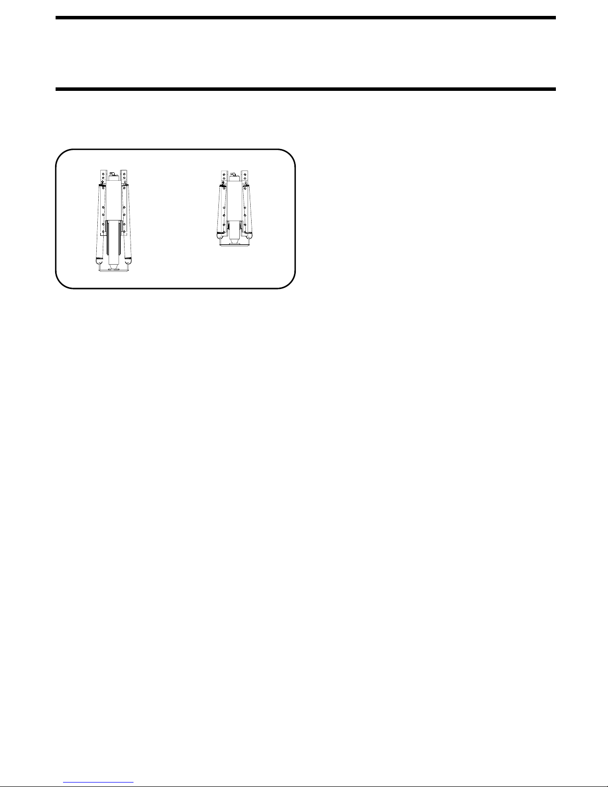
EXTEND POSITION
JACK POSITIONS
CAUTION:
THERE ARE NO OBJECTS UNDER THE VEHICLE AND THAT
ALL PEOPLE ARE CLEAR OF THE VEHICLE.
NOTE:
Retract room extensions before retracting the leveling
system.
1. Start the coach engine to build air in the suspension system.
Press the "I" button and store the jacks immediately. Do not
move the vehicle until the vehicle is at the proper ride height
for traveling.
2. Press the "STORE" button. As each jack retracts, its red
WARNING light will go out. The system will automatically shut
down approximately two minutes after the four individual red
WARNING lights are out.
THE OPERATOR MUST BE SURE THAT
STORE/TRAVEL POSITION
IMPORTANT:
while it is in the STORE mode. DO NOT push the "OFF"
button or turn the ignition key. The system must be allowed
to completely finish the STORE mode. If any one red WARNING
light does not go out the system will continue to store. Push
the "OFF" button and have the system serviced.
CAUTION:
LEVELING JACKS ARE STILL IN CONTACT WITH THE GROUND
OR IN THE EXTEND POSITION. THIS VEHICLE IS EQUIPPED
WITH STRAIGHT-ACTING JACKS. MOVING THE VEHICLE
WITH THE LEVELING JACKS EXTENDED CAN CAUSE
SEVER DAMAGE TO THE JACKS AND OR THE VEHICLE AND
CREATE A DRIVING HAZARD. DO NOT RELY SOLELY UPON
WARNING LIGHTS. IT IS THE OPERATOR’S RESPONSIBILITY TO
CHECK THAT ALL JACKS ARE FULLY RETRACTED INTO
THE STORE/TRAVEL POSITION AND THE VEHICLE IS AT
THE PROPER RIDE HEIGHT FOR TRAVELING.
3. The vehicle can be moved as soon as the suspension air
bags are inflated and the vehicle has returned to the proper
travel height, providing the jacks are in the STORE/TRAVEL
position.
NOTE:
see MANUAL JACK RETRACTION Section.
DO NOT interrupt power to the leveling system
DO NOT MOVE THE VEHICLE WHILE THE
If jacks cannot be retracted by the above procedure
NOTE:
if the "STORE" button on the control panel will not retract the
jacks for travel.
CAUTION:
NOT CRAWL UNDER THE VEHICLE, KEEP A SAFE DISTANCE
IN FRONT AND REAR OF VEHICLE. THE VEHICLE MAY
DROP AND/OR MOVE FORWARD OR BACKWARD WITHOUT WARNING AS THE VALVE RELEASE IS OPERATED.
1. Locate the 4 valve release "T" handles on the solenoid valves.
The solenoid valves are located on the pump/valve assembly.
2. Allow clearance for vehicle to lower.
3. Retract the rear jacks by opening the two outer valves. Slowly
turn the "T" handles counter clockwise. The handles may turn
Use the valve release "T" handles for retracting only
KEEP AWAY FROM THE WHEELS, DO
MANUAL JACK RETRACTION
easily at first but as an internal spring is compressed, turning
may become more difficult. The valves need only to be opened
enough to retract the jack.
4. Retract the front jacks by opening the two center valves as
described in Step 3.
5. Check that all four jacks are now retracted.
6. Close the valves by turning the release handles clockwise.
Once the internal spring tension has been released, the handles
will turn free for several turns. Once the "T" handles are snug,
DO NOT tighten the handles past this point as internal damage
may occur to the solenoid.
7. The system should now be repaired before using again.
MP35.69
12MAR97
Page 7
3
7
MAINTENANCE
.
OIL LEVEL
All maintenance should be done as part of the normal
servicing of the coach.
The oil level should be within one inch of the top of the
reservoir. Most breather caps have a dipstick. Fluid level
should be between the bottom of the dipstick and the
The oil level should be checked when the vehicle is first
center mark.
purchased and then once every two years. More often if
there is an oil leak in the system.
NOTE: Overfilling the tank can cause leakage of oil
through the breather cap.
Any HWH hydraulic equipment, including jacks, slide-outs
and steps should be fully retracted before checking fluid
level. The oil reservoir is part of the pump / manifold
assembly. The oil level is checked and filled through the
breather cap. Clear any dirt away from the breather / filler
cap before removing.
FLUID:
HWH Specialty Hydraulic Oil is recommended. In an
emergency Dexron automatic transmission fluid can be used
NOTE:
Dexron automatic transmission fluid contains red dye
and can cause staining should a leak occur. DO NOT USE
brake fluid or hydraulic jack fluid. Use of these can damage
seals.
ELECTRICAL SYSTEM
The batteries should be in good condition and fully charged.
All electrical connections, especially ground connections,
should be clean, tight, free from corrosion and protected
from corrosion. Weak batteries can cause erratic operation.
Battery cable terminals, battery posts and connections
should be kept clean and protected from corrosion.
UNUSUAL CONDITIONS
If driving conditions are unusually muddy, the jacks may
become caked or clogged with mud. This condition may
hamper the proper operation of the leveling system. This
problem may be prevented or remedied by cleaning off each
leveling jack if they become excessively muddy.
In west or icy weather leveling jacks may become encrusted
with ice. This may cause the leveling system to function
improperly. To eliminate this problem, periodically check the
leveling jacks and break loose any ice which may be
causing improper operation.
Do not move the vehicle while the leveling jacks are still in
contact with the ground. Place the system in the store mode
and then visually check to see if the leveling jacks have
returned to the STORE/TRAVEL position.
NOTE: All major components of the system can be replaced
with rebuilt parts or can be sent to HWH CORPORATION to
be rebuilt, when the system is out of warranty.
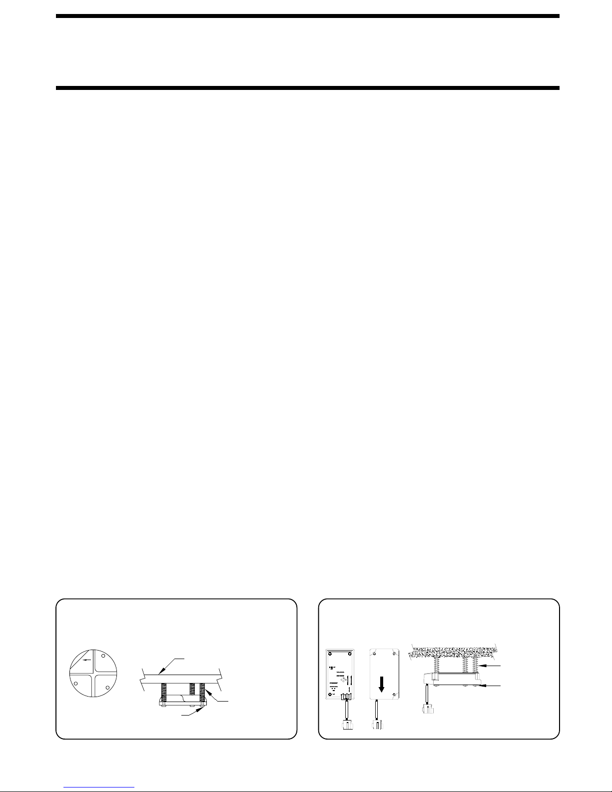
LEVEL SENSING UNIT ADJUSTMENT
Level the vehicle by placing a circular bubble level in the center of the freezer floor or location within the vehicle that
is to be level. With the vehicle level, adjust the sensing unit until all yellow lights are off. This is done by drawing up
the corresponding screw if the sensing unit is mounted below the surface as shown or backing out the corresponding
screw if the sensing unit is mounted above the surface. Bump the sensing unit to see that it is settled tight against all
three screw heads and still indicates that the unit is level.
LEVEL SENSING UNIT
BELOW THE SURFACE MOUNTING
REAR
THIS
SIDE
UP
STICKER
ON TOP
SCREWS (3)
MOUNTING
SURFACE
SPRINGS (3)
ELECTRONIC LEVEL SENSING UNIT
BELOW THE SURFACE MOUNTING
MOUNTING SURFACE
UP
SIDE
THIS
FRONT
SPRINGS (3)
SCREWS (3)
MP45.0
13NOV1
Page 8

TROUBLE SHOOTING
The following is a list of problems, and possible solutions, which might occur to the leveling system.
NOTE:
vehicle’s suspension and electrical system, as well as an understanding of the leveling system’s hydraulics and electronics
is required.
1. JACK RETRACTS AFTER COACH IS LEVEL.
A. Hose or jack has external leak.
2. LEVELING JACKS WILL NOT RETRACT COMPLETELY.
A. Jack clogged with mud or ice.
B. Main rod bent or scored.
C. Springs weak or broken.
D. Hydraulic line pinched.
3. IGNITION SWITCH ON, BUT NO POWER TO PUMP AND/
A. Park brake not set.
B. 12 volts from main power source not present.
Only qualified technicians should install or repair leveling systems on vehicles. A knowledge of hydraulics, welding, the
5. CONTINUED
E. Broken hydraulic line.
B. Fluid is leaking back to reservoir through solenoid valve.
OR LIGHTS.
C. Faulty control box.
F. Bad control box.
G. Bad shuttle valve.
6. LEVELING LIGHTS (YELLOW) NOT FUNCTIONING
PROPERLY.
A. Yellow lights will not go out when vehicle is level: adjust
sensing unit.
B. If more than two yellow lights are on, replace the sensing
unit.
7. WARNING LIGHTS (RED) NOT FUNCTIONING PROPERLY.
A. Light will not come on: check for broken wire at warning
switch on the jack.
B. Lights will not go out bad warning switch or wires are
shorted to ground.
D. Faulty wire or electrical connection.
4. PUMP WILL NOT ACTIVATE
A. Bad touch panel.
B. Bad control box.
C. Pump relay not functioning.
D. Pump not grounded.
5. HYDRAULIC PUMP ACTIVATES, BUT THE JACKS WILL
NOT EXTEND.
A. Bad solenoid valve.
B. Bad manifold pressure switch.
C. Oil supply low in reservoir.
D. Pump is not developing pressure.
C. Check the touch panel.
8. AIR WILL NOT DUMP FROM SUSPENSION
A. Bad control box.
B. Bad touch panel.
C. Air dump solenoid valve bad.
9. SUSPENSION WILL NOT INFLATE
A. Bad control box.
B. Air dump solenoid stuck open.
MP55.07
8SEP95
 Loading...