

Page 1

Poseidon 3266 THset – starting guide HW group
www.HW-group.com
600 282
Starting Guide - Poseidon 3266 THset
First steps with temperature, humidity and open door measuring
Poseidon 3266 THset package contains:
• Poseidon model 3266 [600 252]
• Poseidon T-Box2 [600 280]
• Temperature probe Temp-1Wire 3m
[600 005]
• Humidity probe Humid-1Wire 3m
[600 279]
• Door contact [600 119]
• Power adapter 12V [600 080]
• „Starting Guide“, CD with documentation, manual and Software
1) Connecting of Poseidon 3266 THset
2) IP address configuration - UDP Config
UDP Config start-up file is located in root of supplied CD; latest version can be found on our web:
www.HW-group.com, follow Poseidon 3266 link.
Poseidon 3266 THset
1.1) Check DIP switch. Installation position has to be same like in
the picture (DIP1=Off, DIP2=Off).
1.5) Connect the cable of T-Box2 switch into SENSORS
(RJ12) connector, the connector must click.
1.3) Connect the power adapter to power socket (230 /
110V
)
and connect it to Poseidon power connector.
1.6) Connect Poseidon to Ethernet (direct cable
to Switch, crossed to PC)
1.2) Four inputs are designed for the contact connecting.
Connect the door sensor – part of the start set.
1.4) Connect temperature and
humidity sensors to T-Box2
switch.
Page 2
Poseidon 3266 THset – starting guide HW group
www.HW-group.com
600 282
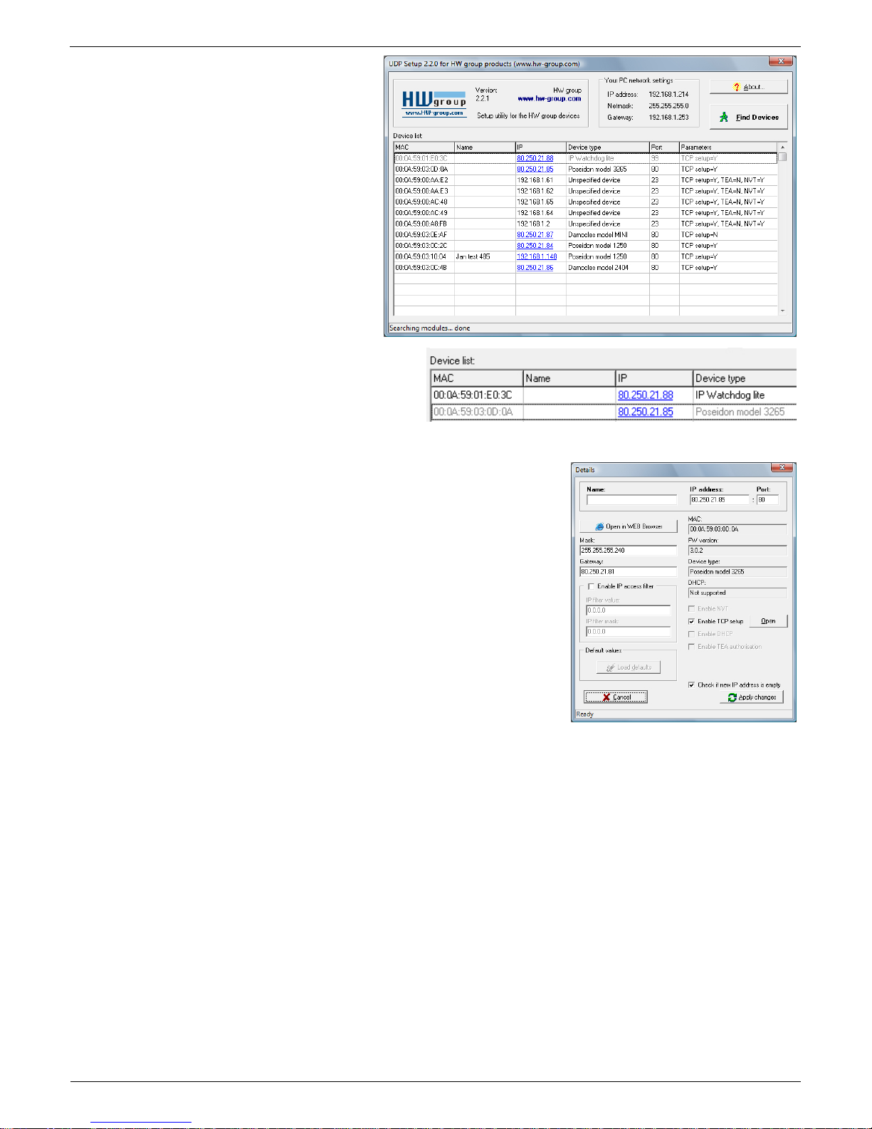
• Click the icon to run UDP Config
program – it will automatically search
for connected devices
In case the device was not connected to
network during UDP Config start-up, you
can easily click the Find Devices button
to repeat the search again.
The Program will search for devices on
your local network. The Poseidon
identifies them according to MAC
address which is printed on label located
on bottom part of each device.
Double click on MAC address will open basic
settings dialog window.
In this moment it is neccesary to setup network parameters.
Notice: In case you do not have following information, contact your
network administrator
• IP address
• HTTP Port
• Mask
• Gateway IP address
• Name of your device - optional
Do not forget to click Apply Changes button to safe new values to
Poseidon memory
Note: to setup IP address you can use as optional:
• Hercules (/Hercules.exe)
• RS-232 serial port (any terminal, DIP1=ON, 9600 8N1)
3) Poseidon configuration – Web browser
3.1) Enter IP address of the device to your web browser address bar or run UDP Config and click
to the IP address.
Page 3

Poseidon 3266 THset – starting guide HW group
www.HW-group.com
600 282
3.2) WWW page Poseidon 3266
•
Current Value – current value of connected sensor. „-999.9“ value means that the sensor is not
available or is initializing after start.
• Safe Range – Sensor´s value range out of Alarm.
• Alarm Alert – defined for sensor, monitoring of safe range switched on and where alert of exceeding
“Safe Range” and Alarm status are sent (inputs for contacts).
• „For more information ..“ – Contact for service organization, you can change it from „Telnet setup“.
3.3) Reading of current values
• XML – values.xml file, format described using XSD – for download on the main page, detailed
comments of XML structure are in the manual.
• SNMP – describing file of poseidon.mib you can download from main page, Standard SNMP port 161
and 162 can be configured in Flash setup.
• Modbus/TCP– structure description is in the manual or in application examples. Standard port 502 is
opened for reading.
Device IP address
Input number for
connect the contact
Input value while
WWW is loaded
Alarm definition for
every input
Device name
Detailed „Flash
setup“ configuration
Description of SNMP
MIB and values.XML
structures
Special configuration
„Telnet setup“
Unique sensor ID
(serial number)
Value out of safe
range alert
Page 4

Poseidon 3266 THset – starting guide HW group
www.HW-group.com
600 282
4) Flash Setup configuration
After the click „Flash Setup“ link from WWW page, the graphic configuration version in browser is
opened. Macromedia Flash player in web browser must be installed. If you don´t have it, you can
download his last version from Internet or find it on CD:
\Poseidon\install_flash_player_7.msi
Using Flash setup you can:
• Setup names of sensors, „Safe Range“ for alarm and where Alarm
alert will be sent.
• Monitor current values, refresh in seconds.
• Select temperature units (°C, °F, °K)
• Setup actual time and NTP server for synchronize the time.
• Setup SNMP parameters (Community names & rights) and define
where to send SNMP Traps
• Setup Alarm alert via email and test it.
• Setup security elements: Names and password, ranges of IP
addresses
More information can be found in manual or on www.HW-group.com.
 Loading...