

Page 1
Poseidon2 – Family manual
HW group
www.HW-group.com
1 / 104
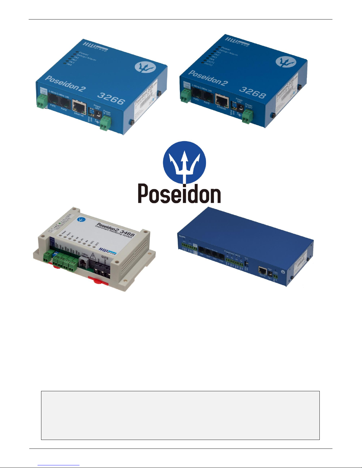
Poseidon2 family
manual
Poseidon2 is a product family for use in remote monitoring and for measuring over LAN.
The family consists of several product versions, designated for use in different
environments (19” rack cabinets, data centres, switchboard cabinets, ..). Specific models
vary in number and types of sensors it can connect, otherwise the devices offer identical
Page 2

Poseidon2 – Family manual
HW group
www.HW-group.com
2 / 104
Table of Contents
Poseidon2 devices ............................................................................................................................. 3
Poseidon2 3266 .............................................................................................................................. 3
Poseidon2 3268 .............................................................................................................................. 3
Poseidon2 3468 .............................................................................................................................. 4
Poseidon2 4002 .............................................................................................................................. 4
Comparison of specific models ....................................................................................................... 5
Connectors description ................................................................................................................... 6
POSEIDON2: FIRST STEPS ........................................................................................ 7
Web interface of the device ............................................................................................................. 9
CONNECTING THE SENSORS ................................................................................. 18
1-Wire Bus (RJ11) sensors ........................................................................................................... 18
RS-485 (RJ45) sensors ................................................................................................................. 19
COMMON FEATURES OF POSEIDON2 FAMILY ..................................................... 20
Supported interfaces (in details)..................................................................................................... 23
Dry Contact Inputs ........................................................................................................................ 23
RJ11 – 1-Wire bus ........................................................................................................................ 24
RJ45 - RS-485 .............................................................................................................................. 27
User interface ................................................................................................................................... 33
UDP Config ................................................................................................................................... 33
WEB interface ............................................................................................................................... 34
Update Firmware ........................................................................................................................... 60
Software Applications .................................................................................................................... 61
CONNECTING POSEIDON2 TO SENSDESK PORTAL ............................................ 63
Connecting to the portal ................................................................................................................ 63
USING POSEIDON2 UNITS IN YOUR APPLICATIONS ............................................ 67
PosDamIO – Command line control .............................................................................................. 67
HWg-SDK ...................................................................................................................................... 68
Poseidon formats and interfaces ................................................................................................ .... 75
SMS – Interface description .......................................................................................................... 75
E-mail – Interface description ........................................................................................................ 76
XML – Interface description........................................................................................................... 79
Logger format ................................................................................................................................ 87
Modbus over TCP – Interface description ..................................................................................... 89
HWg-netGSM - remote SMS gateway protocol for HW group products ........................................ 91
SNMP – Interface description ........................................................................................................ 97
SNMP Trap – Interface description ............................................................................................. 101
Connectors and connections ........................................................................................................ 104
Page 3
Poseidon2 – Family manual
HW group
www.HW-group.com
3 / 104
Poseidon2 devices
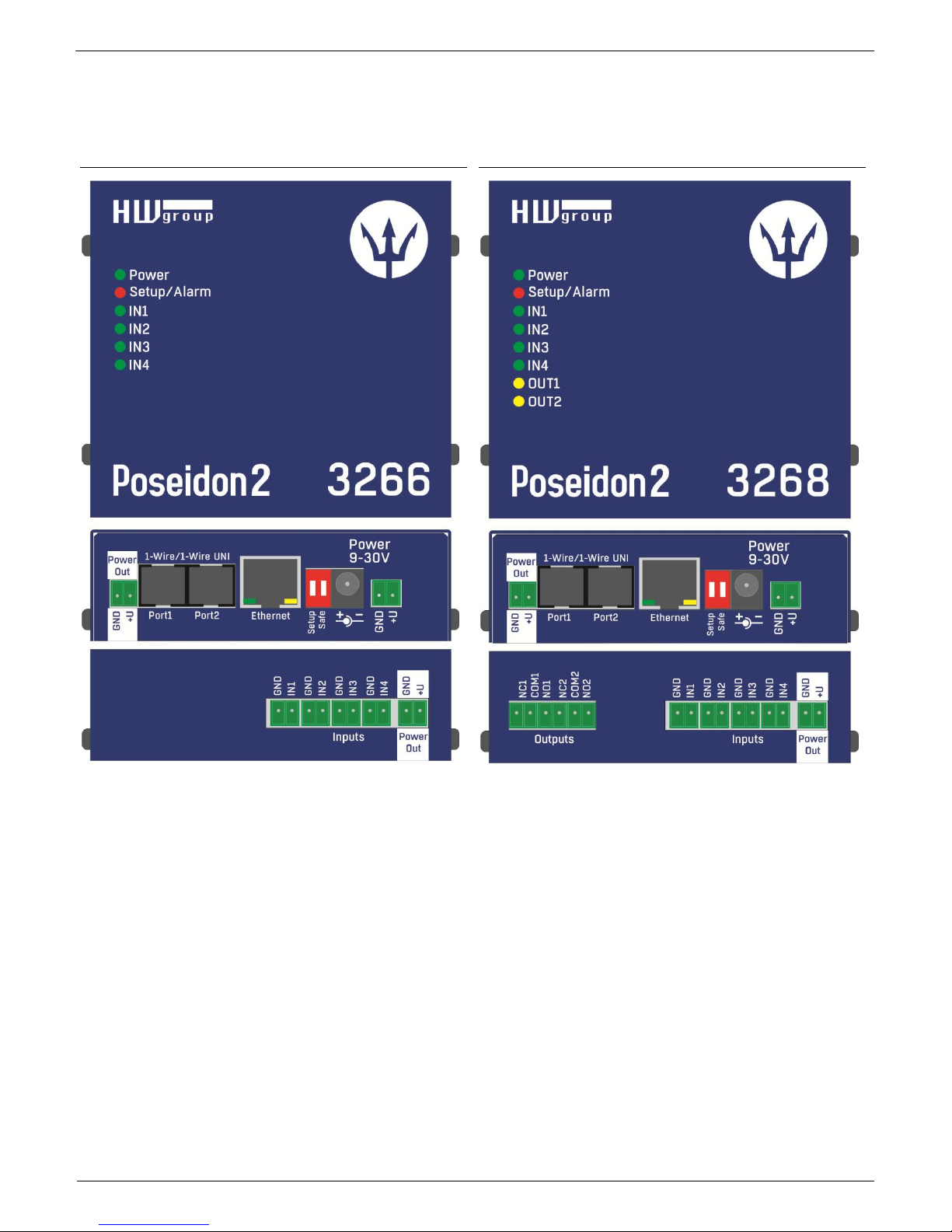
Poseidon2 3266
Poseidon2 3268
Page 4
Poseidon2 – Family manual
HW group
www.HW-group.com
4 / 104
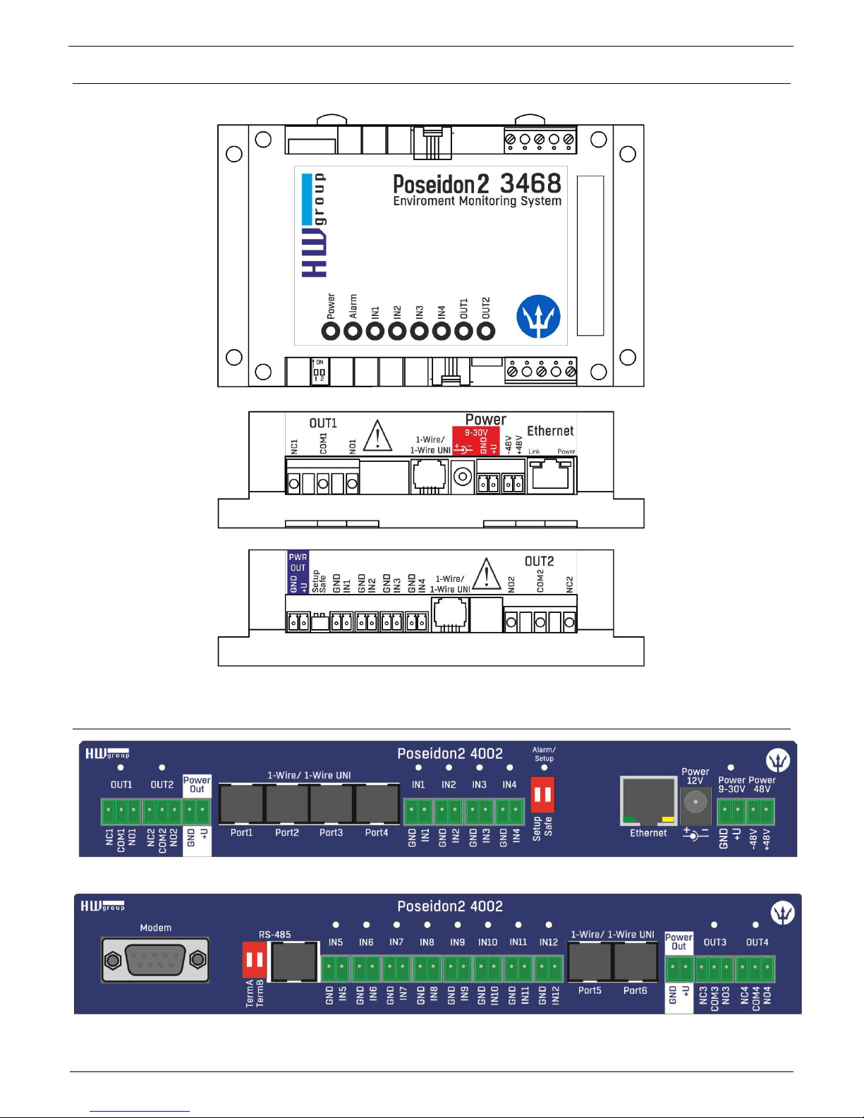
Poseidon2 3468
Poseidon2 4002
Page 5
Poseidon2 – Family manual
HW group
www.HW-group.com
5 / 104
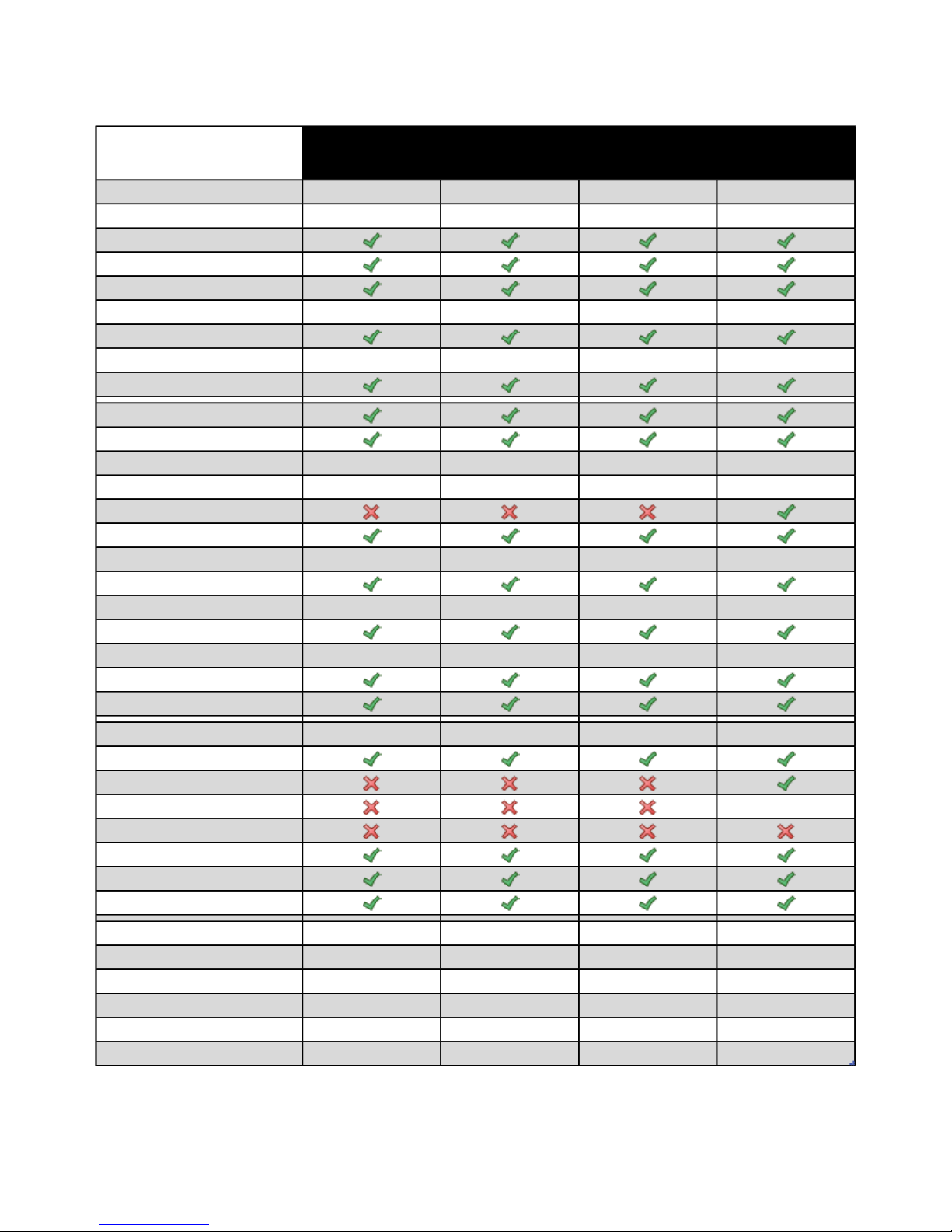
Comparison of specific models
Poseidon2
3266
Poseidon2
3268
Poseidon2
3468
Poseidon2
4002
Ethernet 100 Mbit 100 Mbit 100 Mbit 100 Mbit
VLAN future future future future
HTTP
DHCP
SNMP v1
SNMP v2/3 future future future future
SNMP Trap
Trap destinations 5 5 5 5
SNTP
SMTP
SMTP TLS
E-mail Destinations 5 5 5 5
SSL future future future future
SMS/ Local RS-232
SMS/ netGSM
SMS Destinations 5 5 5 5
Logger
Logger reccords 250.000 250.000 250.000 250.000
HWg-Push protocol
IPv6 future future future future
Comm monitor
DO Local conditions
1-Wire sensors 8 8 8 16
1-Wire UNI support
RS-485 support
RS-485 sensors 24
M-BUS meters
Modbus /TCP
Email Alarm reminder
Email Periodical Status
Power Input 1 9-30V 9-30V 9-30V 9-30V
Power Input 2 -- -- 48V DC --
DI (Digital Inputs) 4 4 4 12
DO (Digital Outputs) 0 2 2 4
DO max load -- 50V/1A 230V/10A 50V/1A
Operating temperature -30-85°C -30-85°C -30-50°C -30-85°C
Page 6
Poseidon2 – Family manual
HW group
www.HW-group.com
6 / 104
Connectors description
Ethernet
Ethernet 100Base-T (10/100Mbit). After connecting the adapter a green "Link" LED shows correct
connection and yellow "Activity" LED flashes
Power
Green LED light shows that the device is powered-up. Power supply in range 930V is required, for Poseidon2 3268 it is 48V. Modules can be manufactured in
PoE versions for use in specific projects
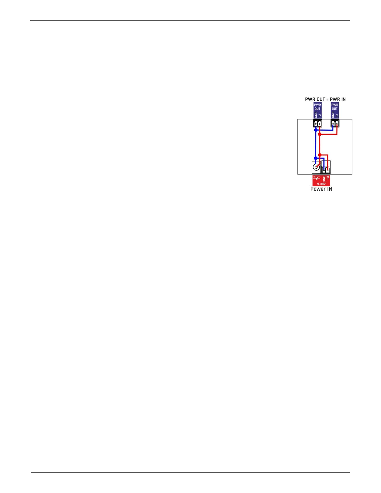
PowerOut
Can be used as a power supply for connected sensors and accessories.
PowerOut output is directly connected to 9-30V input. Power outputs on units that
require 48V can be used as a 12V/300mA power supply.
1-Wire/1-Wire UNI
Connecting HWg sensors with 1-Wire/1-Wire UNI interface. Each port can directly connect up to 60m
bus. 2 Wire UNI sensors. More in chapter Connecting the sensors
RS-485 (only Poseidon2 4002)
For connecting RS-485 HWg sensors. TermA and TermB switches are used for bus termination.
More in chapter Connecting the sensors
Inputs
INx - Inputs for connecting dry contacts. All inputs have one common GND potential. Green LED light
shows that the input is triggered.
Outputs
OUTx – relay outputs with switch contacts. Clamps connected in normal state are NCx (Normally
closed) + COMx (Common), NOx (Normally Open) + COMx when the relay is switched. Yellow LED
light shows that an output is switched.
Alarm/Setup LED
Red LED shows the device state - Light indicates alarm state (some sensors or inputs out of their
safe range), flashing indicates that the device is in TCP or Serial Setup.
DIP1/DIP2 system switches
DIP1 - Serial setup mode activation / Factory default settings switch. Factory default settings can be
restored by switching the DIP1 3x within 5 seconds after connecting the power adapter.
DIP2 - Safe mode - Switching the DIP activates HWg settings protection. No settings can be
changed.
Page 7
Poseidon2 – Family manual
HW group
www.HW-group.com
7 / 104
Poseidon2: first steps
1) Connecting the cables
Turn the unit and write down its MAC address that is printed on the label on the side.
Set the switches: DIP1=Off, DIP2=Off.
Connect the unit to the Ethernet (with a patch cable to a switch, cross-over cable to a PC), RJ-
45 port.
Plug the power adapter into a mains outlet and connect it to the Poseidon2 power input.
The green POWER LED lights up.
If the Ethernet connection works properly, the LINK LED lights up after a short while, and then
flashes whenever data are transferred (activity indication).
2) Configuring the IP address – UDP Config
UDP Config utility – root directory of the supplied CD (Windows and Linux versions).
Available for download at www.HW-group.com Software > UDP Config.
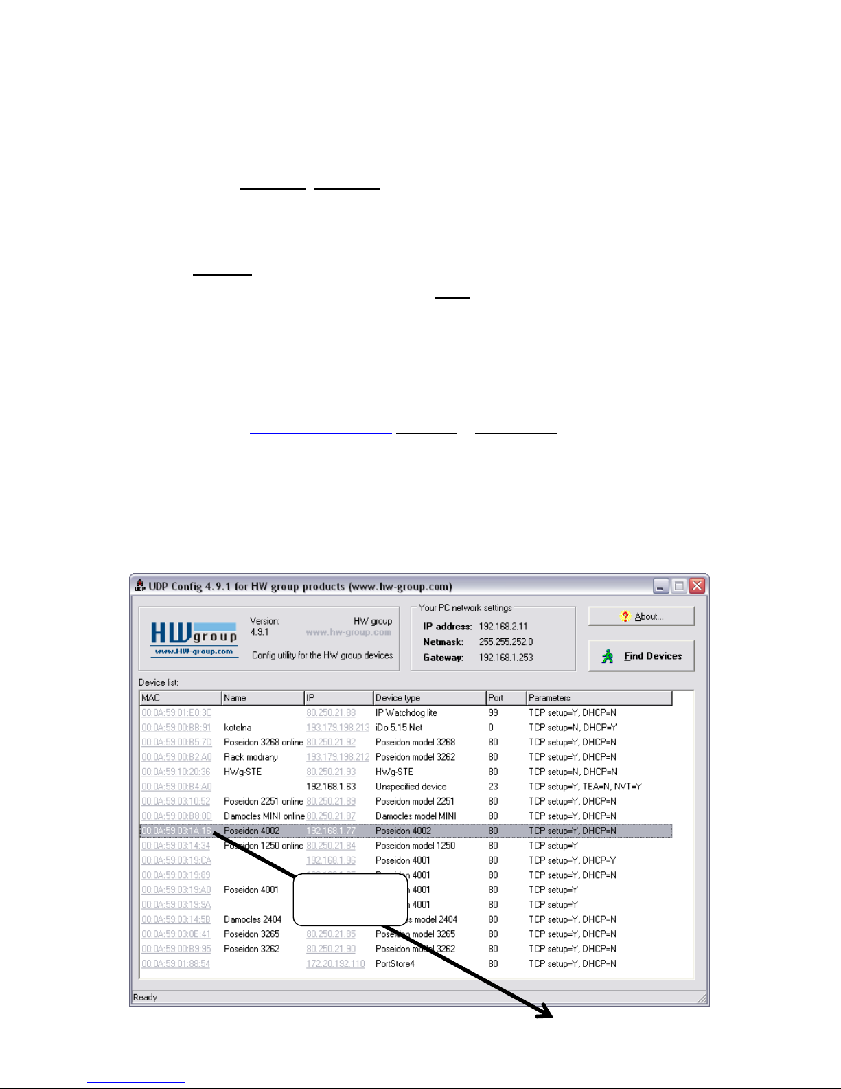
Click the icon to launch UDP Config. The program automatically looks for connected devices.
Automatic device discovery works only in the local network.
Individual Poseidon2 units are identified by their MAC addresses (on the label at the bottom).
Double-click a MAC address to open a basic device configuration dialog.
Double click for
details
Page 8
Poseidon2 – Family manual
HW group
www.HW-group.com
8 / 104
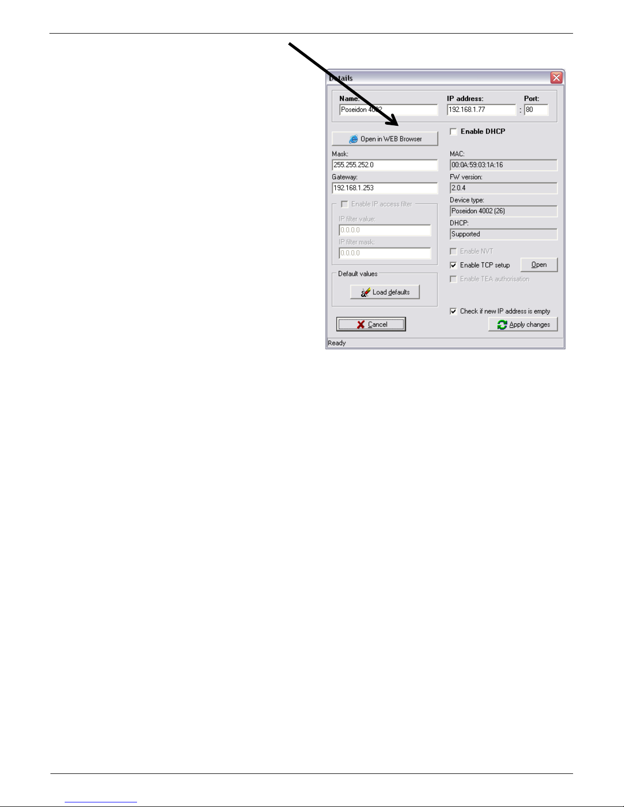
Configure the network parameters
IP address / HTTP port (80 by default)
Network mask
Gateway IP address for your network
Device name (optional)
Click the Apply Changes button to save the
settings.
Alternatively, you may use the following utilities to configure the IP address:
UDP Config for Linux
Important:
To reset the device to factory defaults, toggle DIP1 several times within 5 seconds after
applying power to the device.
No configuration changes can be stored while DIP2=On.
To change the IP address, set DIP2=Off.
Page 9
Poseidon2 – Family manual
HW group
www.HW-group.com
9 / 104
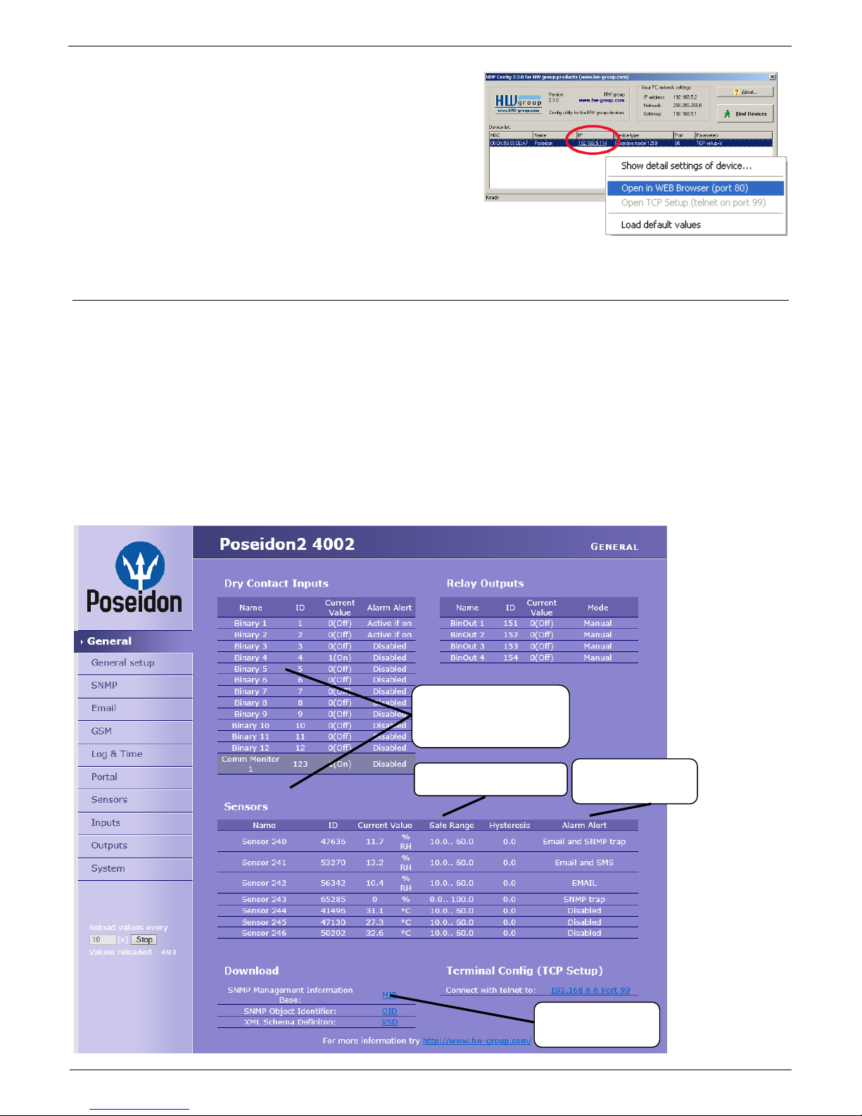
4) WWW interface of the device
To open the WWW interface of the device:
o Enter the IP address into a web browser
o Click the IP address in UDP Config
o Click the underlined IP address in UDP
SETUP
The WWW page displays current states of devices and sensors.
Web interface of the device
General: Overview of current readings
General Setup: IP address, DNS, security (user name/password)
SNMP: SNMP / SNMP Trap configuration (ports and alarm recipients)
E-mail: Configuration and test
GSM & RFID: Configuration and test in order to use a remote SMS-GW
Log & Time: Time configuration, NTP server
Portal: Connection to a remote portal system
Sensors: Device name, sensor names, status overview
Inputs: Control of inputs and alert parameters
System: Firmware upgrade, save/restore configuration, etc.
Action when value
out of range
Alarm thresholds
MIB file for SNMP
softwares
User-defined names for
sensors and digital
inputs
Page 10
Poseidon2 – Family manual
HW group
www.HW-group.com
10 / 104
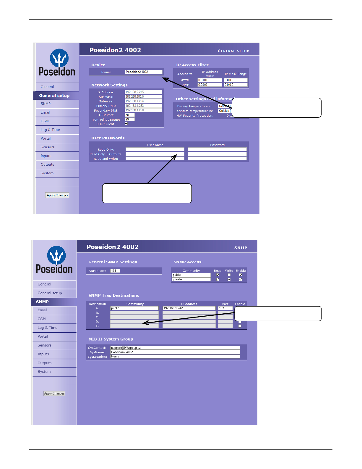
General Setup
SNMP
Device name, e.g.
“First floor 1”
5 destinations for SNMP Traps
Three levels of passwords for
device security.
Page 11
Poseidon2 – Family manual
HW group
www.HW-group.com
11 / 104
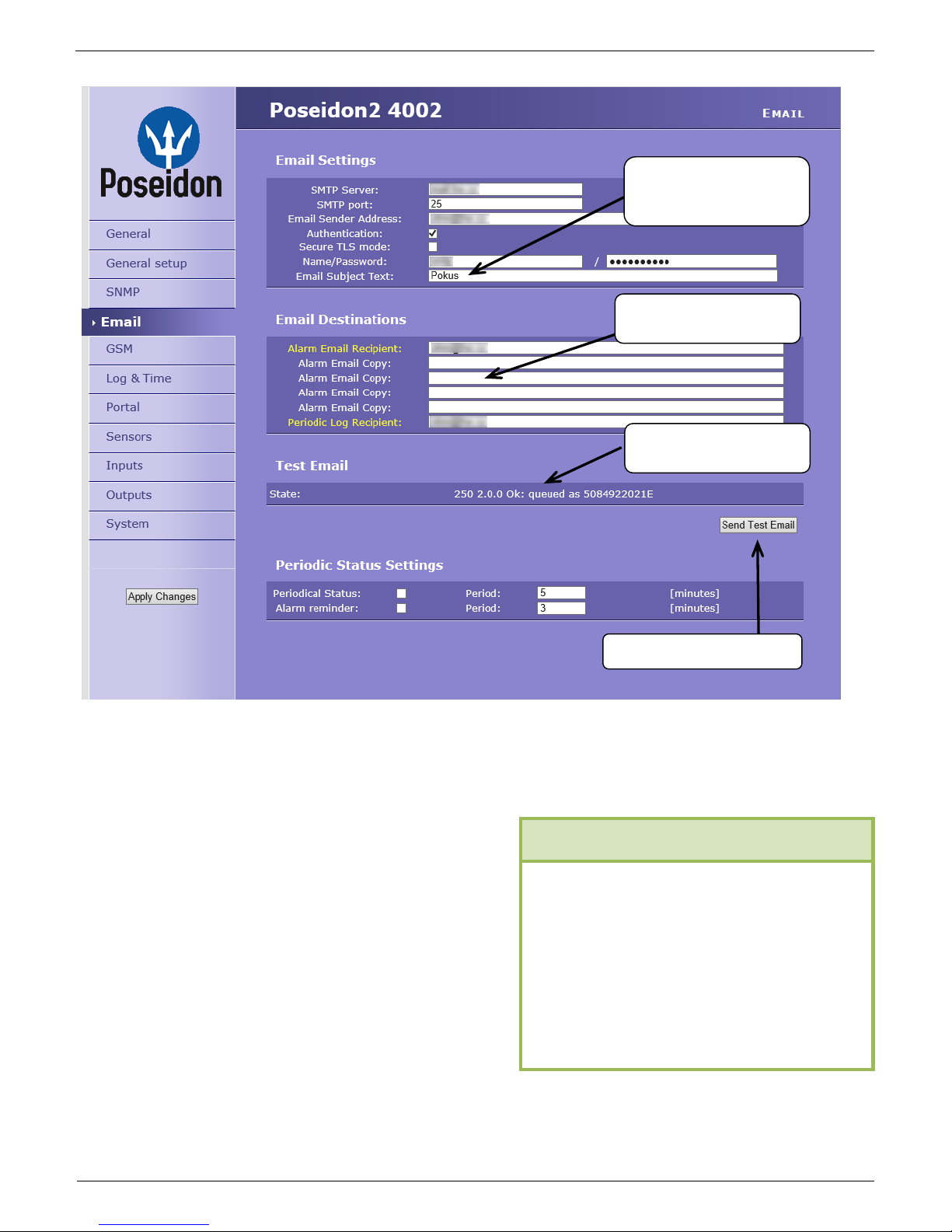
E-mail
Periodic Status Settings
Periodical Status
When on, sends an e-mail with device status at the specified intervals. For example
every 24 hours (1440 minutes).
Alarm reminder
When active, sends periodic reminders
that the device is in the Alarm state. For
example every 15 minutes.
NOTE: Configuration changes must be confirmed by clicking the Apply Changes button.
Sends a test E-mail
Inserts this text at the
beginning of the e-mail
subject line
Up to 5 recipients for
alarm e-mails
E-mail test result
1) Correct Gateway IP address
2) DNS server in network settings
3) SMTP server and port
4) Authentication turned on, correct
user name and password
5) Spam filter for your mailbox is
disabled
To send e-mail, check:
Page 12

Poseidon2 – Family manual
HW group
www.HW-group.com
12 / 104
GSM
Log & Time
Press to synchronize the
time with the specified
server
Interval for logging
measured values
Expected size of recorded
data
IP address of “HWg-SMS-GW”
to use for sending text messages
(SMS)
Recipients' phone numbers
Page 13
Poseidon2 – Family manual
HW group
www.HW-group.com
13 / 104
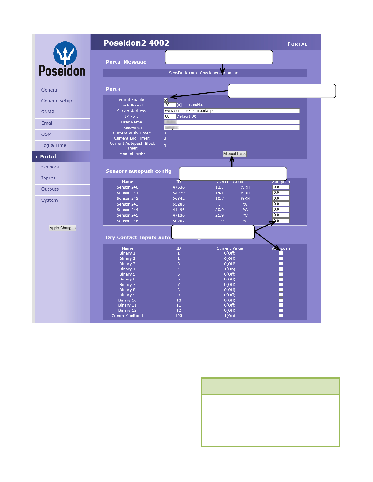
Portal
Configures the communication with the portal using the HWg-Push protocol. Poseidon2 is the active
side and establishes the connection periodically and/or whenever a change in a sensor value
exceeds the configured AutoPush value.
The www.SensDesk.com portal connection parameters are filled in.
AutoPush configuration
Poseidon2 connects to the portal and notifies a value
change whenever a change in the sensor reading
exceeds the configured AutoPush value.
This configuration only applies to the communication
between Poseidon2 and the online portal. Local
alarm values are configured in the portal.
Enable connection to the remote portal
Message from the portal
AutoPush configuration
Click to connect to the portal
1) Correct Gateway IP address
2) DNS server in network settings
3) Correct Server Address of the
portal
For portal connection, check:
Page 14
Poseidon2 – Family manual
HW group
www.HW-group.com
14 / 104
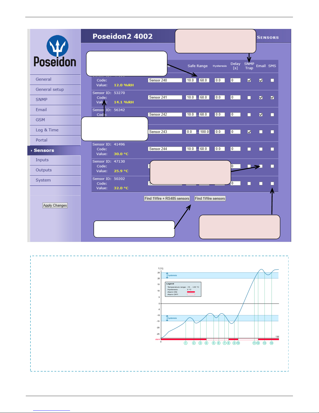
Sensors
After connecting sensors or changing RJ11 connections, sensors need to be detected again.
NOTE: Configuration changes must be confirmed by clicking the Apply Changes button.
Sensor name will be shown
in e-mails, text messages,
or SNMP traps
Sends a SNMP trap if the “Safe
Range” for this sensor is
exceeded
Scans connected sensors and
displays detected sensors
Sends an E-mail if the “Safe
Range” for this sensor is
exceeded
Sends a text message (SMS) if
the “Safe Range” for this sensor is
exceeded
Range of allowed values. If
exceeded, alarm is signaled.
To avoid numerous false alerts
(by e-mail or SMS) whenever the reading
fluctuates around the threshold,
you can use:
1) Hysteresis Idle Range
Tolerance band around the
“Safe Range”. Prevents
multiple alarm alerts.
2) Delay [s]
Delays the information about
alarm beginning and alarm
end by a specified time. Can be used for dry contacts, too.
Tip: For details, see the complete “Poseidon family” manual.
Page 15
Poseidon2 – Family manual
HW group
www.HW-group.com
15 / 104
Poseidon2 informs about alarm
activation and deactivation for
each Digital Input and/or sensor.
E-mail format cannot be changed;
sensors may have custom names.
Yellow background in a line with a
sensor or an input means that the
safe range is exceeded but alarm
notification is off.
FAQ
Connecting the inputs
Inputs
NOTE: Configuration changes must be confirmed by clicking the Apply Changes button.
Enter Digital Input name,
will be shown in e-mails,
text messages or SNMP
traps
ALARM CONTACT STATUS:
Active if On
Alarm when the contact
closes (1 = On)
Active if Off
Alarm when the contact
opens (0 = Off)
Disabled
No Alarm
Reaction to digital inputs:
Disabled
Send a SNMP Trap
Send an E-mail
Send a SMS
0 (Off)
1 (On)
Page 16

Poseidon2 – Family manual
HW group
www.HW-group.com
16 / 104
Outputs
Pulse Timer – After clicking this option the output will switch for a defined time.
Pulse Timer = 0 function inactive Details can be found in the manual in chapters
about WEB interface.
Output mode:
A) Manual
Output can be controlled using the Web interface or externally using M2M protocols. The
output cannot be used in “thermostat” mode – local condition.
B) Local Condition
The output cannot be controlled over the Web, it is controlled by the local condition. The
output is read-only for all M2M protocols. Hysteresis in the sensor settings applies.
Outputs cannot be controlled via web or M2M protocols in Local Condition mode.
o On if any alarm
The output is active if at least one input or sensor is in alarm.
o On if value equal to Trigger
The output is active if the selected sensor reading is equal to the “Target Value”.
o On if value higher than Trigger
The output is active if the selected sensor reading is greater than the “Target Value”.
o On if value lower than Trigger
The output is active if the selected sensor reading is less than the “Target Value”.
Choose the output mode
Manual mode:
Output controlled over the WEB
or M2M protocols
Local Condition mode:
Controls the output according to
the specified sensor
Enter Digital Input name,
will be shown in e-mails,
text messages or SNMP
traps
Pulse output timer [s].
Default Pulse Timer = 0 sets
Page 17
Poseidon2 – Family manual
HW group
www.HW-group.com
17 / 104
o On if Alarm on
Output = On, if the selected sensor or input is in an Alarm state.
o Dependent On – sensor / input to which the condition applies.
System
Communication Monitor
This function is useful e.g. to send a warning e-mail whenever Poseidon2 ceases to be periodically
monitored over SNMP or SCADA.
This function controls a virtual Digital Input that is available in Inputs as “Com Monitor 1” with an ID
of 123. If no communication took place in the specified time using the selected protocols, it sets “Com
Monitor 1” = 0 (Off).
If three protocols are selected, all 3 conditions must be met for the OK state.
Configuration
Download – Retrieve the configuration from the device and store it on the PC.
Upload – Send a saved configuration from the PC to the device.
NOTE: Configuration changes must be confirmed by clicking the Apply Changes button.
Uploads new firmware from
the PC
Restoring factory defaults
Page 18
Poseidon2 – Family manual
HW group
www.HW-group.com
18 / 104
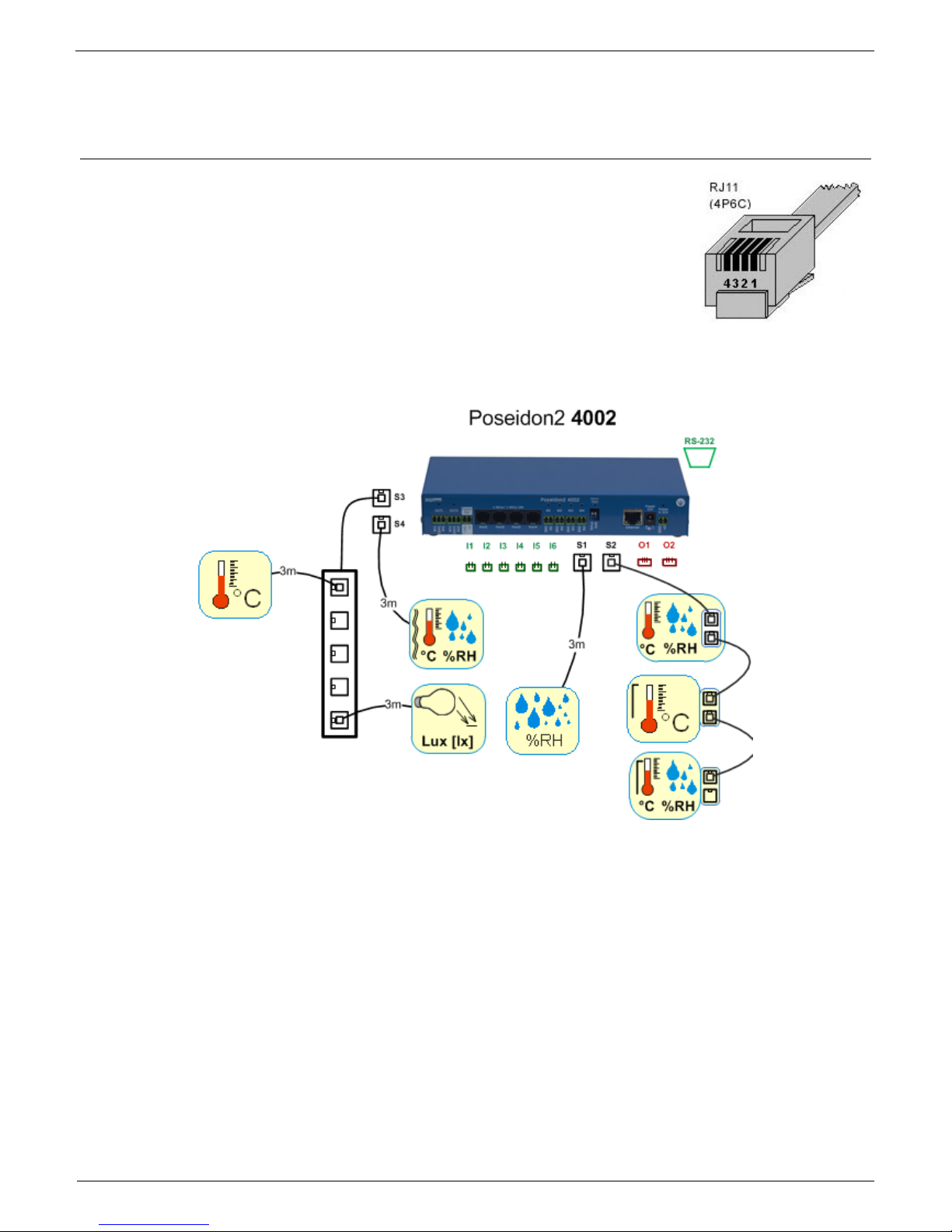
Connecting the sensors
1-Wire Bus (RJ11) sensors
Connect the sensor before powering up the Poseidon - the connector
must click in.
Max distance per active port is 60m.
Sensors can be daisy-chained.
Sensors can be also connected using a star topology with the T-Box
(TBox2) hub.
After any change in the connected sensors an autodetection has to be run again.
(WWW interface > Sensors > Autodetect sensors )
Max
distance
Page 19
Poseidon2 – Family manual
HW group
www.HW-group.com
19 / 104
RS-485 (RJ45) sensors
Industrial bus for connecting sensors over longer distances
Connect the sensors before powering up the unit.
Sensors can be daisy-chained, or connected to a virtual star using
the “S-Hub” unit.
Terminate the RS-485 line with a 120 Ω to 470 Ω terminator. Some
sensors (e.g. Temp-485) contain a built-in terminator controlled with
a jumper or a DIP switch (TERM = ON). See the sensor manual.
Check or set the sensor address. Each sensor on the RS-485 bus must have an unique
address. The address (ID) is expressed as a letter (A..Z / a..z) or a number (65..122). The
numbers correspond to the ASCII codes of the letters, A=65, Z=90, a=97, z=122.
More details on setting up the address in sensor manuals.
After any change in the connected sensors an autodetection has to be run again.
(WWW interface > Sensors > Autodetect sensors )
Sensors are shipped with non-conflicting addresses whenever possible. The preset address is written
on the label.
Note: A particular sensor is identified by its RS-485 address. Sensors with the same
address can be swapped without the need for a new detection.
Page 20

Poseidon2 – Family manual
HW group
www.HW-group.com
20 / 104
Common features of Poseidon2 family
Displayed readings options
The Poseidon2 unit displays current readings from all connected sensors.
Dry contact inputs are scanned approximately every 200ms.
Values from all sensors on both buses (RS-485 and 1W bus) are read in a single loop that
repeats once per second; however, the actual time needed to read the sensors may vary
from 1 to 30 seconds
All values are in the “integer/10” format, range is ±999.9.
A value of 999.9 is out of range for all supported sensors and indicates that the sensor was
not found.
If you have disconnected or replaced a sensor, run sensor autodetection, or remove
the sensor from the list.
When the Poseidon2 unit is overloaded with network requests (as is sometimes the
case, for example, with our public online demo), -999.9 can sometimes appear even
though the sensor works properly. This is due to limited computing performance of the
unit. Try to reduce the load.
Units are assigned to values automatically according to the detected sensor type. Supported
units include:
Temperature: °C, °K, °F
(please note that Safe Range thresholds can be set in °C only)
Humidity: %RH
Voltage: V, current: A or mA
Other units: %, etc...
Input / sensor in alarm state
Alarm state can be set independently for every input (contact) / sensor.
For a sensor, “Alarm” occurs whenever the reading is outside of the specified Safe Range,
as long as alarm alerting is enabled for at least one notification method (SNMP / e-mail &
SMS).
Response to a sensor being disconnected
-999.9 is displayed
The value evaluates as an “Alarm” (reading out of the specified Safe Range). If alarm
alerting is enabled for the given sensor, e-mail or SNMP trap is sent.
• More information about data formats, variables
identification and SDK can be found in Thorough Poseidon
family manual.
TIP
Page 21
Poseidon2 – Family manual
HW group
www.HW-group.com
21 / 104
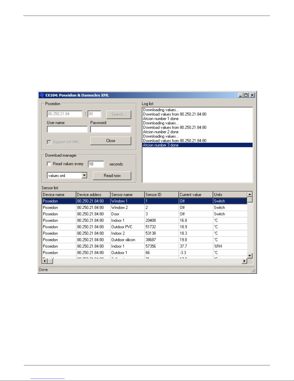
Calibration
Each sensor can be calibrated by specifying a linear offset. The calibration value can be
written over XML. For calibration settings use the Calibrator utility (For download on
Poseidon 2250 websites) or EX104 from HWg SDK (menu can be opened by a right-click).
Calibration value = +3 → sensor measures 0,5°C → Poseidon shows +3,5°C
Calibration value = -3 → sensor measures 0,5°C → Poseidon shows -2,5°C
Calibration value = -10 → sensor measures 27% RH → Poseidon shows 17% RH
Page 22
Poseidon2 – Family manual
HW group
www.HW-group.com
22 / 104
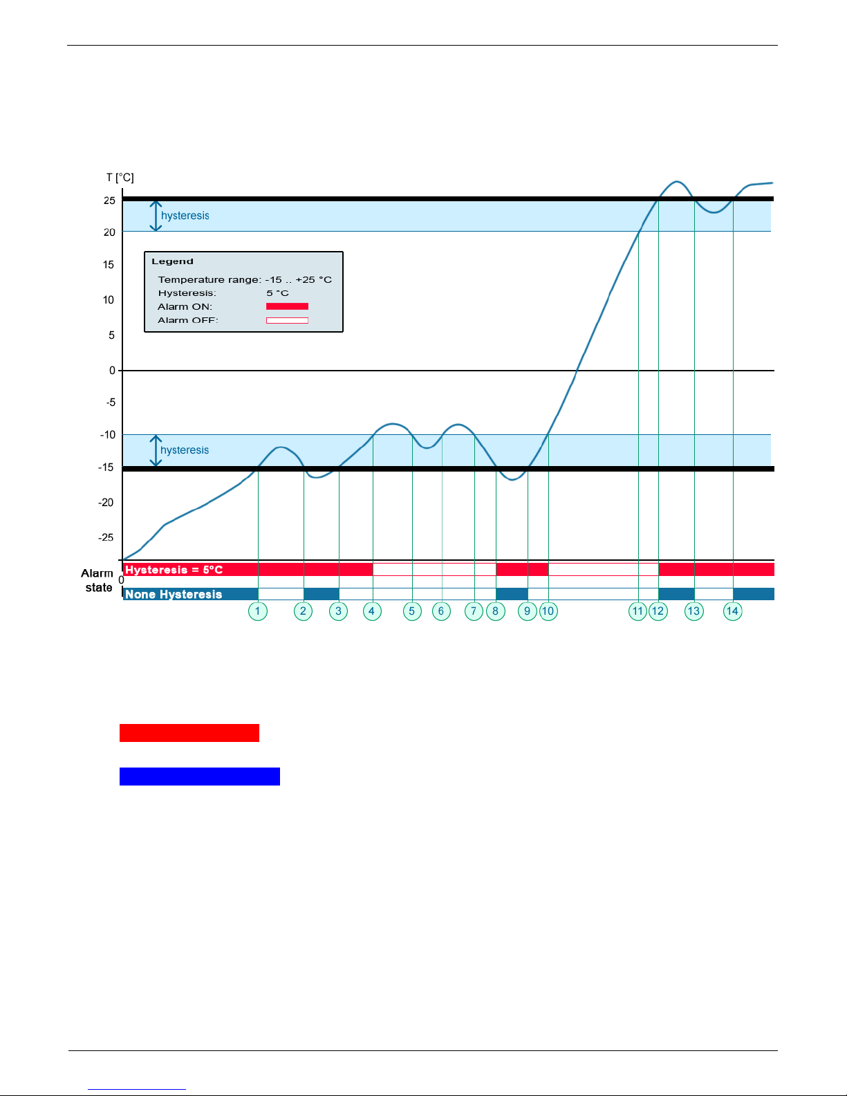
Sensor hysteresis
The Hysteresis setting defines a tolerance band for alarm alerts. This feature prevents multiple
alarm alerts if the reading oscillates around the specified threshold. See the graph for an
explanation.
Without a hysteresis of 5°C, the alarm raised at point 8 would end at point 9. With the hysteresis
function, the alarm continues until the temperature rises above the tolerance band (point 10), that is,
5°C + (-15°C) = -10°C.
Hysteresis = 5°C: The unit sends 3 e-mails (SMS)
Alarm at points 0..4, 8..10, 12 and beyond
No hysteresis (0°C): The unit sends 8 e-mail (SMS) messages Alarm active in
points 0..1, 2..3, 8..9, 12..13, 14 and beyond
Page 23
Poseidon2 – Family manual
HW group
www.HW-group.com
23 / 104
Supported interfaces (in details)
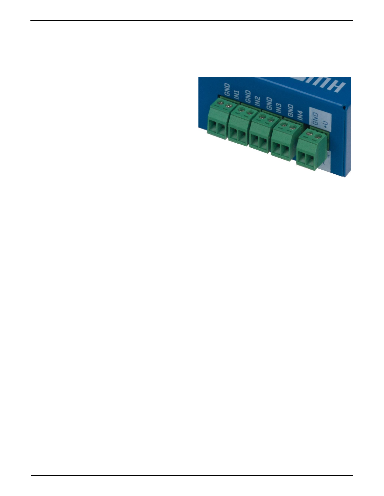
Dry Contact Inputs
Dry contacts can be connected to the clamps. For
example Door contact.
The inputs are electrically connected to the power
supply.
Unconnected inputs read as “0 (Off)”.
Activated inputs (closed contacts) read as
“1 (On)”, resistance against the Common
pin must not exceed 500Ω.
Connection parameters:
Maximum wiring length: 50 m
Supported sensors: Any contact without external voltage (dry contact)
Per-input alarm settings:
o Alarm inactive
o Alarm when the contact is opened or closed
o Alarm whenever the contact is open
Possible alarm responses: Common setting for all inputs
o No response
o Alarm alert sent as a SNMP trap
o Alarm alert sent by e-mail or text message (SMS)
o Alarm alert sent as a SNMP trap as well as by e-mail or SMS
Polling period: 800 ms
Range of sensor IDs: Inputs use ID addresses from 1 to 9
Sensor names: Sensors can be named using up to 12 characters
Disconnected sensor detection: None, disconnected sensor reads as “O (Off)”.
Page 24
Poseidon2 – Family manual
HW group
www.HW-group.com
24 / 104
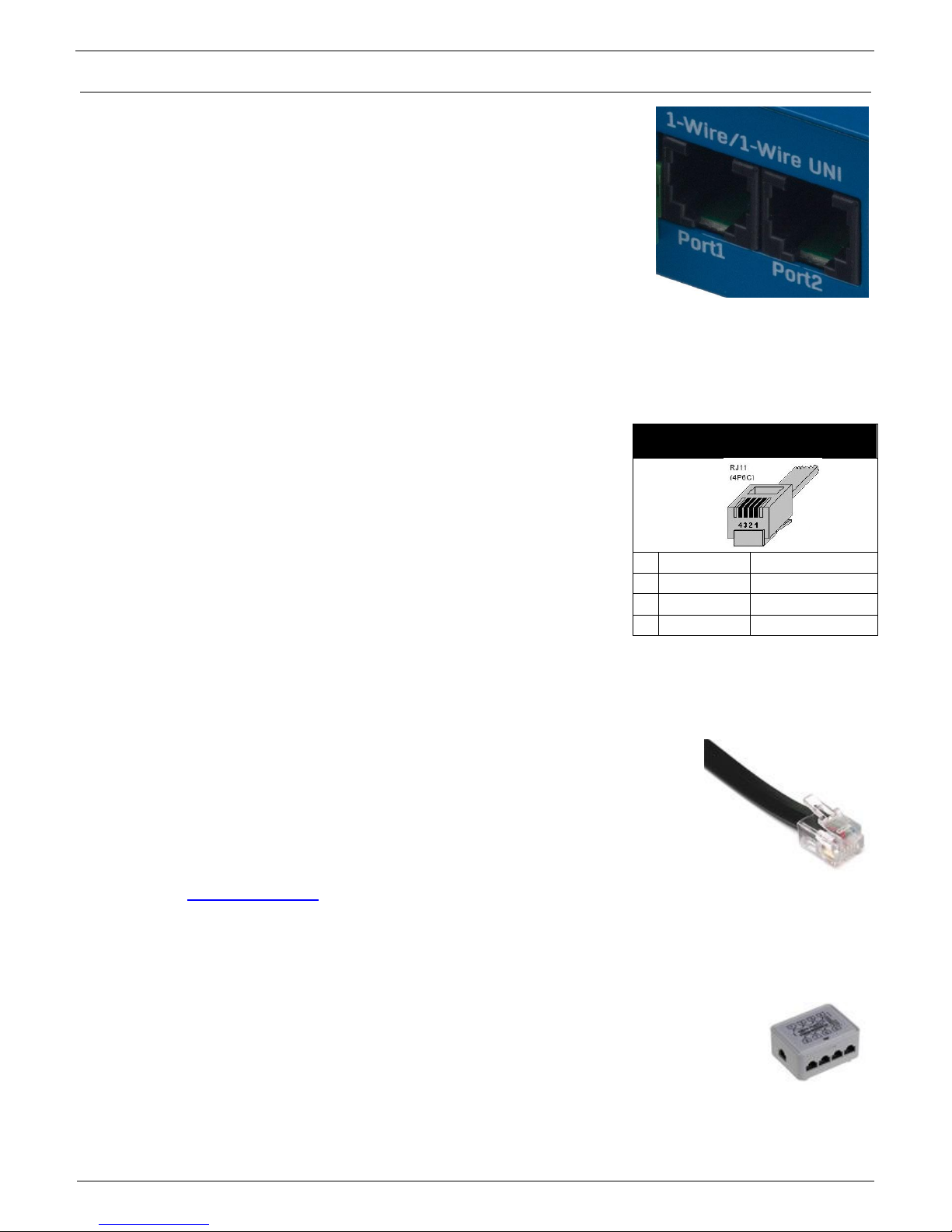
RJ11 – 1-Wire bus
Digital bus from company Dallas Semiconductor, each sensor has its
own unique ID.
We recommend to keep the total wiring length under 60m, although
functionality has been achieved over tens to hundreds of meters in
experimental settings.
If the wiring connected to one connector of the Poseidon2 unit is longer
than approximately 60m, we cannot guarantee error-free operation,
as it greatly depends on the actual wiring implementation, topology and
environment.
Active / Passive 1W port
Active is RJ11 connector on a Poseidon2 device. Full max length
and power supply is guaranteed for all 1-Wire UNI/1-Wire sensors.
If you move a connected sensor from one active port to another, the
sensor will be shown as disconnected. After connecting, run sensor
autodetection again.
Passive port is an RJ11 connector on T-Hub or an RJ11 connector
on a sensor (for daisy-chaining). Cannot guarantee full length and
power supply for following sensors. Power supply issues can be
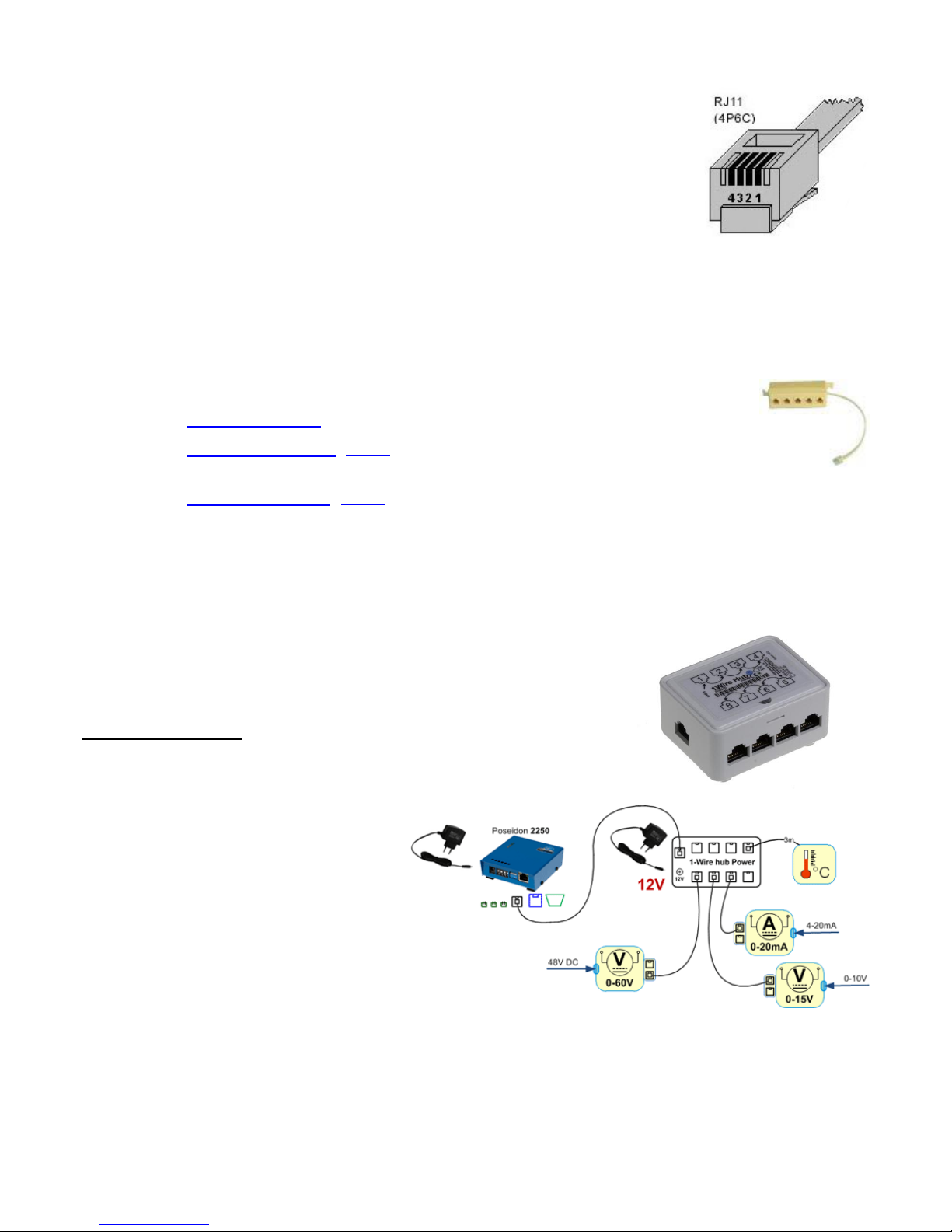
resolved by using 1-Wire hub Power.
1-Wire UNI (RJ11)
1-Wire UNI is a software extension of 1-Wire bus.
1-Wire UNI sensors:
o Illumination sensor
o Sensor 4-20mA
o Sensor 0-60V (-48V DC)
o Sensor 0-30A AC
o >> More sensors
Maximum wiring length: 60 meters total length per each active RJ11 port
Note: Length can be limited by some 1-Wire UNI sensors or by using more RJ11 male-female
connectors.
Power to sensors: 5V/20 mA from RJ11 connectors (can be boosted by "1-
Wire hub Power")
Other parameters are identical with 1-Wire
RJ11
1 - Not used
2
Data
Transmit Data
3
GND
Ground
4
+5V
Power
Page 25
Poseidon2 – Family manual
HW group
www.HW-group.com
25 / 104
1-Wire (UNI) bus
Supported sensors: Only new sensors supplied by HW group
1-Wire UNI: Software extension "UNI" show other than temperature or
humidity sensors.
Communication cable: 4-wire phone cable
Polling period: 800 to 10 seconds
Sensor address assignment: Automatic, each sensor has a unique address
Disconnected sensor detection: Yes, disconnected sensors read as “-999.9”
Alarm if sensor is disconnected: If the sensor is set to alarm whenever its reading is outside
of the safe range, disconnection triggers the alarm
1-Wire bus accessories
o Poseidon T-Box - Hub for 5 1-Wire / 1-Wire UNI sensors
o 1-Wire hub Power (photo) - hub + additional power supply for 8 1-Wire /
1-Wire UNI sensors
o Poseidon T-Box2 (photo) - Hub for 2 1-Wire / 1-Wire UNI sensors
Remember: All 1Wire bus sensors have their unique serial numbers. These are stored with
sensor names during autodetection and expressed using the sensor IDs. If you
change the sensors on the bus, you must re-run Autodetection in the Flash
SETUP.
Special accessories for the 1Wire bus
1-Wire hub Power – Power booster + Hub for 8 sensors
1x Input: 1-Wire bus
1x input: 12VDC power
8x output: 1-Wire bus
Compatible with
1-Wire and 1-Wire UNI bus.
Page 26
Poseidon2 – Family manual
HW group
www.HW-group.com
26 / 104
Poseidon T-Box2 – Hub for 2 sensors
Cable length: 1m
Maximum number of connected sensors: 2
Connectors: RJ11
Bus type: 1-Wire bus
Poseidon T-Box – Hub for 5 sensors
Cable length: 10cm
Maximum number of connected sensors: 5
Connectors: RJ11
Bus type: 1Wire bus
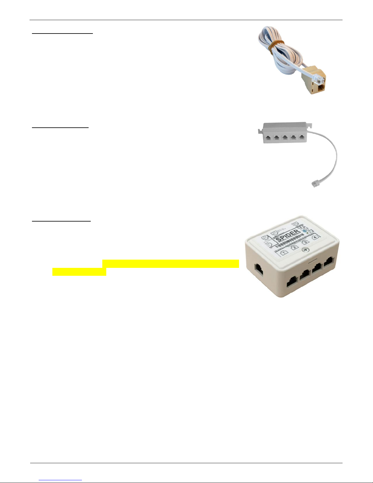
Poseidon Spider – Bridges 1-Wire bus to RS-485
The Spider unit connects to the Poseidon2 over the Industrial
bus (RS-485)
Spider unit can connect 4 sensors over 1-Wire bus
Spider supports ONLY sensors for temperature, humidity and
dry contact inputs.
Each sensor is connected to a separate connector and may be
located up to 25m away.
Maximum number of connected sensors: 4x 1-Wire
Sensor types: 1-Wire bus (1-Wire) (Does not support 1-Wire UNI)
Connects to: RS-485
Caution: The Poseidon2 unit warranty explicitly excludes failures caused by connecting
sensors made by other manufacturers or with excessively long wiring.
Page 27
Poseidon2 – Family manual
HW group
www.HW-group.com
27 / 104
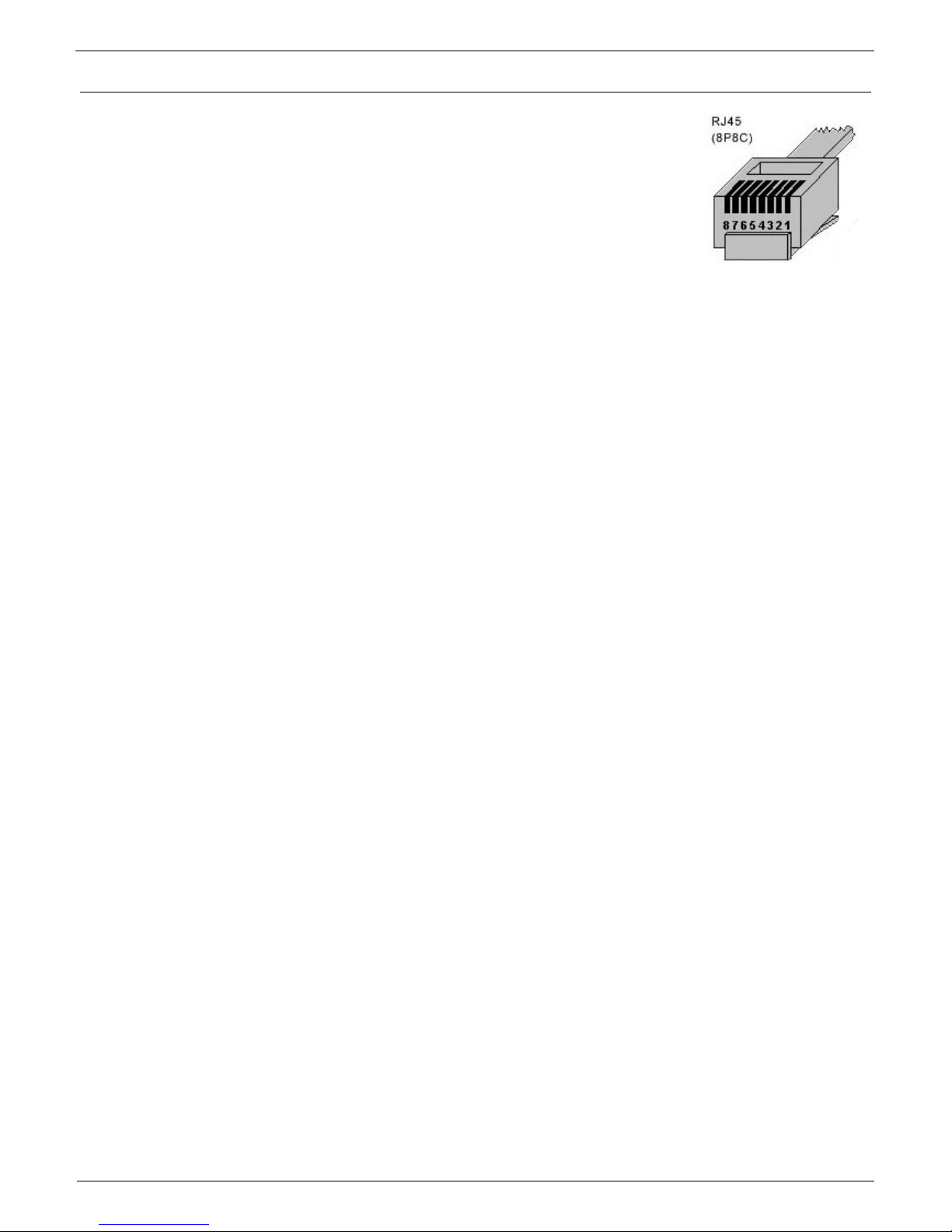
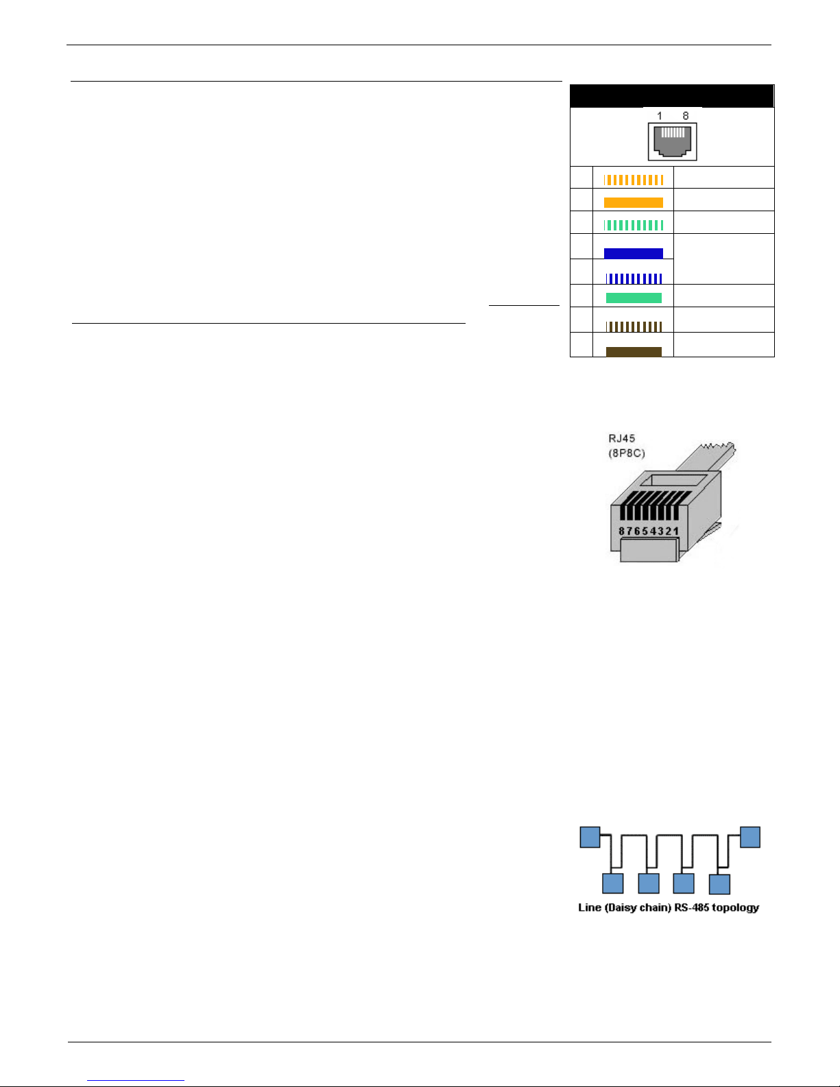
RJ45 - RS-485
The RS-485 bus can be used to connect up to 31 sensors over up to
1000m, even in industrial environments. For convenience and ease of
use, TP cables and RJ45 modular jacks are used to wire the RS485
industrial bus.
The RS-485 bus uses the blue pair of wires (pins 4 and 5), labeled A
and B. The brown pair (pins 7, 8) is used to supply 12V to power the
sensors.
If you use the S-Hub unit and the B-Cable module, the green pair of
wires (pins 3, 6) is used for the return RS-485 connection. The green
pair of wires is not connected at the Poseidon2 4002 unit.
Maximum wiring length: Up to 1000m in total
Supported sensors: temperature, humidity, current, voltage sensors and others (more in
Sensors overview in our product list)
Number of sensors on the RS-485 bus: Up to 31 physical
sensors
Power: 12V/120 mA, available at the RJ45 jack. Power supplied
by the bus is sufficient for up to 3 external sensors, an S-Hub can
be added to power more sensors
Communication cable: Twisted 2-wire UTP, eventually 4-wire
phone cable
Alarm settings: Monitoring of the measured values (SafeRange)
Polling period: 800 ms to 10 s (depending on the number of sensors, 10 seconds for 41
sensors)
Sensor address assignment: Manual, each sensor must have a unique address (see
sensor manual)
Range of sensor IDs: Sensors use IDs from 48 to 122, the address corresponds to the
ASCII code of 0..9, A..Z, a..z characters.
Disconnected sensor detection: Yes, disconnected sensors read as “-999.9”
Alarm if sensor is disconnected: If the sensor is set to alarm whenever its reading is
outside of the safe range, disconnection triggers the alarm
General RS-485 characteristics
Maximum wiring length 1000 m
Up to 32 devices on the bus (Poseidon unit + 31 sensors)
High resistance to noise in industrial environments
Daisy chain topology is necessary (as opposed to star topology)
Each device must have a unique address
Wire polarity must be respected
Line must be terminated at the beginning and at the end
Port 1 – RJ45
1
-
Not used
2
-
Not used
3
-
485 B return
4
B (-)
RS-485
5
A (+)
6
485 A return
7
GND
Ground
8
+12V
Power
Page 28
Poseidon2 – Family manual
HW group
www.HW-group.com
28 / 104
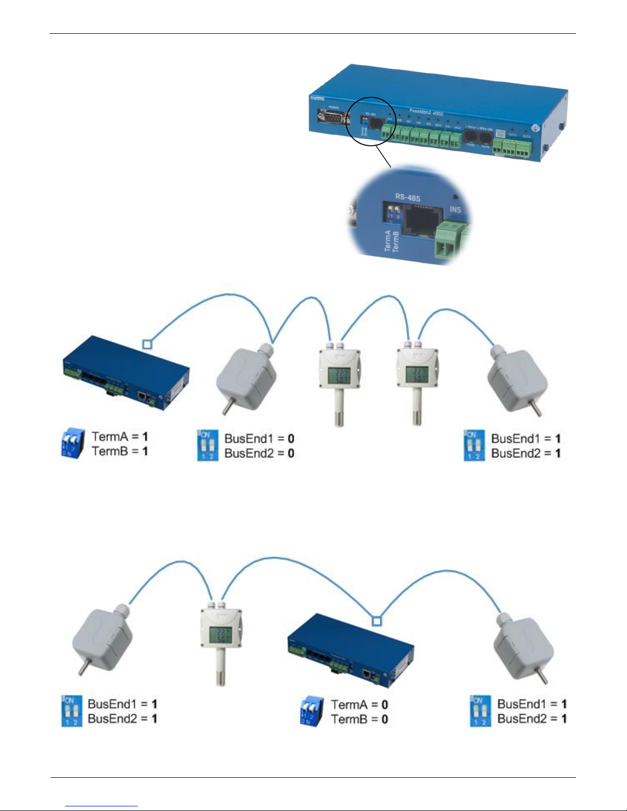
RS-485 termination on the side of Poseidon2
Poseidon2 4002 units are equipped with two
DIP switches (TermA and TermB) for RS-485
bus termination.
Poseidon2 4002 at the start of RS-485 line
Poseidon2 4002 in the middle of RS-485 line
Page 29
Poseidon2 – Family manual
HW group
www.HW-group.com
29 / 104
Termination of RS-485 bus
The RS-485 bus must be terminated at its end. The following options are available:
Internal jumper on certain sensors (jumper named TERM or TERMINATOR) – for example
Temp-485 or HTemp-485
B-Cable adapter with “LAST” configuration selected using the switches
By an external resistor for sensors that do not have clamp connector or a DIP switch
(Temp-485-Pt100). Terminate the RS-485 with an external resistor at the end of the bus
(connect the resistor between clamps A and B on the last sensor).
Value of this resistor is 120Ω. For short wirings, 470 Ω can be used to reduce the current
consumption of the sensors.
Note: A disadvantage is that it is necessary to have a wiring topology with a single
beginning and a single, terminated end, as opposed to the popular star topology with a single
interconnection point.
Special accessories for the RS-485 bus
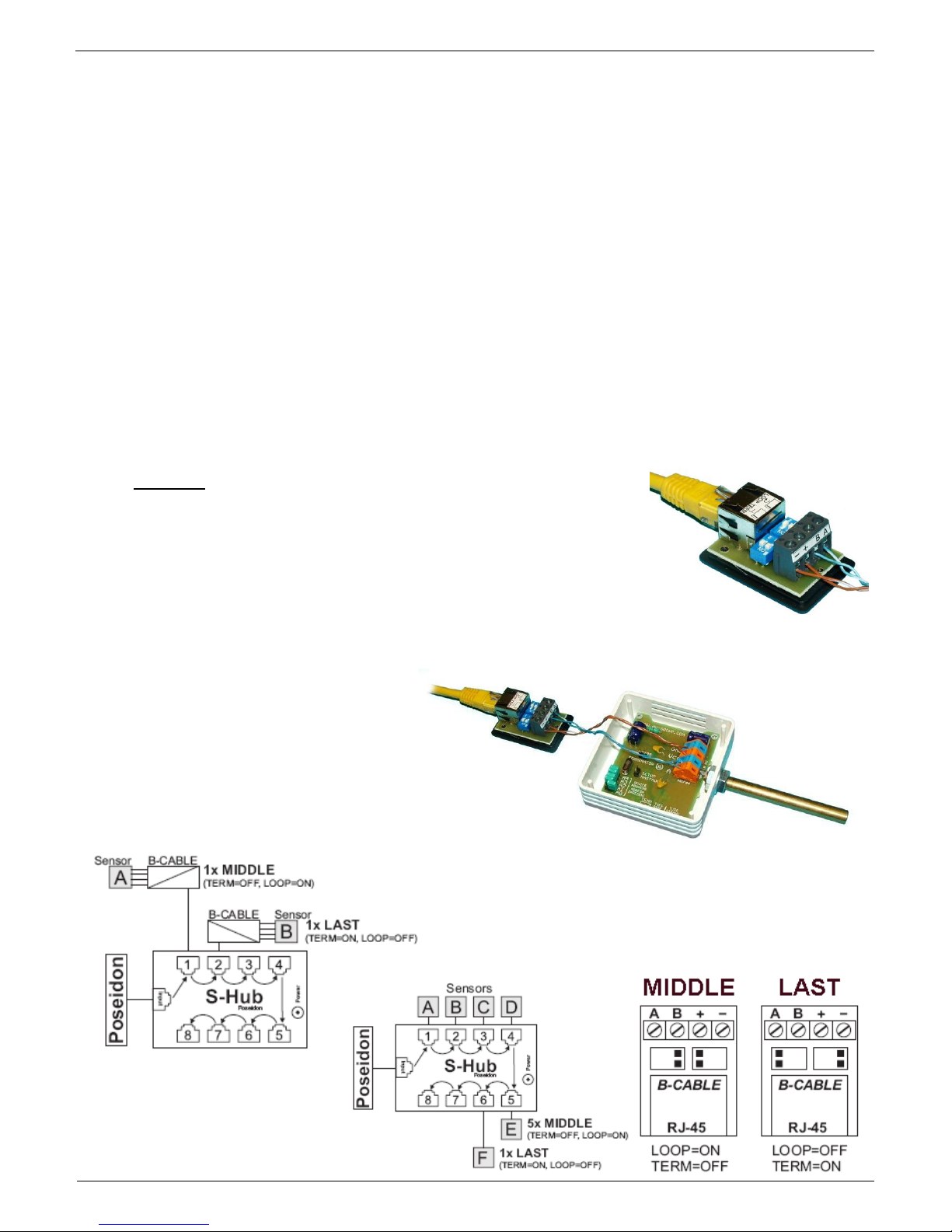
B-Cable - RJ45 / 4-wire connection
The B-Cable module is an adapter that converts a RJ45 jack
connection to a block of 4 terminals A,B,+,–.
Some of the available RS-485 sensors already have a RJ45
jack; however, some only have 4 terminals labeled A,B,+,- .
Such sensors can be connected to the Poseidon 1250 unit or to
an S-Hub using either a TP cable (4 or 6 wires) or the B-Cable
module.
The 4-wire connection
length should not exceed
20 cm.
Sensor position on the RS-
485 bus (MIDDLE / LAST)
is selected with jumpers;
see the picture for details.
Page 30
Poseidon2 – Family manual
HW group
www.HW-group.com
30 / 104
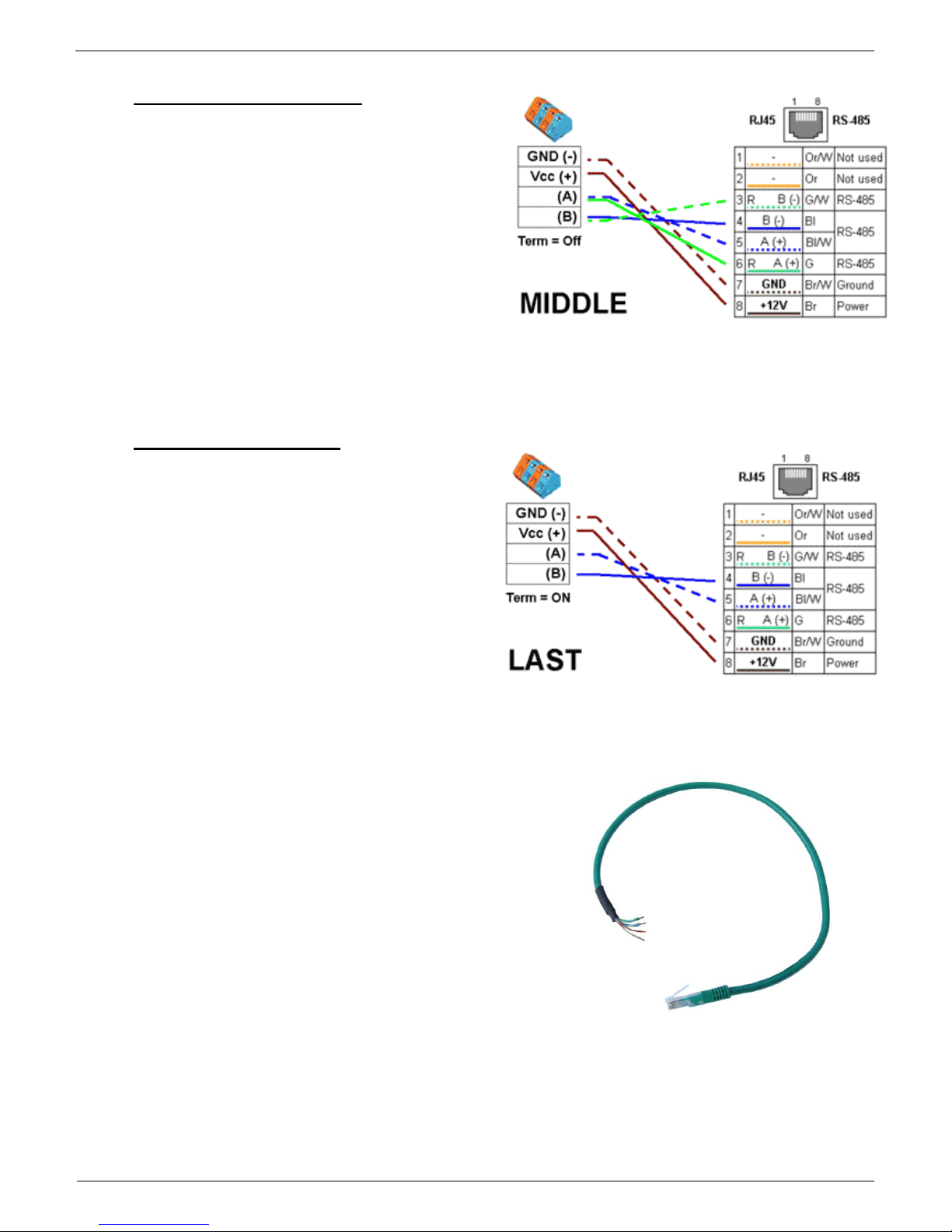
Sensor RJ45 MIDDLE cable
RS-485 cable, 0.5m, RJ45/4 pins. Connects
4 terminals (A, B, +, - ) to a RJ45 modular jack
(uses 3 pairs).
This cable is used to connect all sensors
except for the last one in the chain.
Sensors connected with this table must not
terminate the RS-485 bus.
Sensor RJ45 LAST cableRS-485 cable,
0.5m, RJ45/4 pins. Connects 4 terminals (A,
B, +, - ) to a RJ45 modular jack (2 pairs
only).
This cable is used to connect the last sensor
in the chain.
The sensor connected with this cable MUST
TERMINATE the RS-485 bus in one of the
following ways:
Equipped with an external 120Ω resistor
Jumper or DIP switch at the sensor set to TERM=ON
For other options, see the sensor manual
Page 31

Poseidon2 – Family manual
HW group
www.HW-group.com
31 / 104
Poseidon Spider
A converter to connect four 1Wire sensors to the Industrial bus (RS-485).
Each 1Wire bus sensor connects to a separate connector to enable a greater
distance (up to 1000 meters, as defined by the Industrial bus specification).
S-Hub – 8x RJ45 TP hub
The S-Hub unit with one input and 8 output ports is used
to connect up to eight RS-485 sensors with TP cables.
Makes it possible to connect sensors in a star
topology (sensors must be connected using TP
cables)
Simpler and faster connection of sensors
Makes expanding an installation easier
Easier way of powering the sensors. A standard power adapter connects directly to
the S-Hub unit.
Note: It is possible to mix the star / daisy-chain topologies with S-Hub, see the
examples in the following chapter.
Page 32

Poseidon2 – Family manual
HW group
www.HW-group.com
32 / 104
Connection example via RS-485
The bus leads via a 4-wire connection from a Poseidon 1250 unit to two daisy-chained sensors,
Temp-485 and HTemp-485. Two twisted pairs are used for the connection.
An S-Hub unit is daisy-chained via the RJ45 jack to the second HTemp-485 sensor using a 4-wire
connection. The brown pair carries power, the blue pair is used for data.
Temp-485 and HTemp-485 sensors are connected to S-Hub connectors 1 through 3 using 6-wire
connections (brown pair for power, blue pair leads the bus to the device, green pair back from the
device).
Connector 4 of the first S-Hub unit is used to connect a Spider converter with a patch cable. The
Spider is used to connect three Temp-1Wire 10m sensors and one contact (door contact connects to
the blue RJ45 pair).
The second S-Hub unit is connected with a patch cable to the Spider output.
Temp-485 and HTemp-485 sensors are connected to S-Hub connectors 1 through 3 using 6-wire
connections (brown pair for power, blue pair leads the bus to the device, green pair back from the
device).
Connector 4 connects a Temp-485 sensor over a 4-wire connection (brown pair to power the sensor,
blue pair for the A/B signals of the bus).
Termination is enabled at the Temp-485 sensor using the "TERM" jumper.
°C %RH
°C
°C
°C %RH
°C
°C
°C %RH
°C
°C
RJ45 4 pins
RJ45 Patch Straight Cable
4 pins, LAST (Terminated)
1 2 3 4
Spider
10m
°C
10m
°C
10m
°C
Cat5 TP cable, 3 pairs used
RJ12
2 wires cable
Cat5 TP cable, 2 pairs used Telephone cable, 2/3 wires used
RJ45, MIDDLE cable
RJ45, LAST cable
Term=ON
Mode=MIDDLE
Poseidon 1250
Temp-485
HTemp-485
Temp-1Wire
Door Contact
S-Hub
1 2
3
4
IN
OUT
1 2
3
4
Page 33

Poseidon2 – Family manual
HW group
www.HW-group.com
33 / 104
User interface
UDP Config
UDP Config is a freeware utility for assigning IP addresses and changing network settings over the
Ethernet.
Windows and Linux version
IP address is assigned to a product with a specific MAC address
No installation is necessary, simply run the EXE file
Provides a clear overview of device names and parameters
Main features
Concise graphical environment
Device name, type, MAC address, IP address
and communication port is displayed after a
device is found
Compatible with all HW group products
(Poseidon, Damocles, PortBox, PortStore, I/O Controller, IP relay and other product lines)
Windows and Linux versions available
Displays current network settings of your computer
Verifies whether the IP address is available before assigning it
Single-click access to the product web page
Ability to open a Telnet session for TCP Setup
Ability to restore factory-default settings
Detailed program description as well as an instructional video clip are available on the CD supplied
with the device, or at our website: http://www.hw-group.com/software/udp_config/index_en.html
Page 34

Poseidon2 – Family manual
HW group
www.HW-group.com
34 / 104
WEB interface
Basic communication interface
Poseidon offers a simple and user-friendly graphical WWW interface. Besides displaying current
readings, the interface provides access to complete device configuration and management, including
network settings, sensor configuration and alarm responses (SNMP traps).
To access the web interface, enter the Poseidon IP address into the URL field of your browser:
The main page with the overview of sensor and input readings automatically reloads every 10
seconds. This period can be easily changed.
Page 35

Poseidon2 – Family manual
HW group
www.HW-group.com
35 / 104
Dry Contact Inputs
This section displays current states of dry contact inputs, including alarm status and settings. Active
alarm is indicated by a red background of the corresponding line.
Name (Input name)
Textual name of the input, assigned by user in the Flash Setup
Number
Unique input ID, as marked on the unit
Current Value
0 (Off) – Open contact
1 (On) – Closed contact
Alarm Alert
List of alarm alert settings for each input (triggered by value out of safe range)
Line background color:
Standard color = Input is not in alarm
Red = Input is in alarm
Sensors
The Sensors table displays information (valid at the time of the last refresh) about detected and
activated sensors, including their states.
Name (Input name)
Textual name of the input, assigned by user in the Sensors tab.
ID
16-bit ID of the sensor, unique within a particular device
Current Value
Current sensor reading, including the unit
Note: If a sensor is not connected, -999.9 is displayed.
Safe Range
A range of values in which the sensor is not in alarm state.
Hysteresis
hysteresis settings for preventing repeated alarms when the value moves around the Safe
Range value. More in chapter Sensor hysteresis.
Alarm Alert
List of alarm settings for each sensor (alarm is triggered by reading out of the safe range)
Page 36

Poseidon2 – Family manual
HW group
www.HW-group.com
36 / 104
Line background color:
White / no color = Input is not in alarm
Red = Input is in alarm
Yellow = Alarming is disabled for this input but the value is out of the safe range
Miscellaneous information
Terminal Configuration (TCP Setup)Link containing the IP address and the port to open a
terminal session for TCP Setup
MIB links to the SNMP definition file
(right-click the link and select “Save Target as…” to save the file to disk)
OID - SNMP Object Identifier - Contains a list of most frequent SNMP OID
(right-click the link and save the file to your hard drive with "Save Target as.." option
XSD links to the XML definition file for values.xml(right-click the link and select “Save
Target as…” to save the file to disk)
Text and link “For more information try www.HW-group.com”
Customizable link to the supplier or service provider. The text can be changed in TCP Setup,
see the detailed description of TCP Setup.
Note: The design of the main page can be changed only after consulting the manufacturer;
we offer a “Customization” program. For more information, please contact your dealer.
Page 37

Poseidon2 – Family manual
HW group
www.HW-group.com
37 / 104
General Setup
Network parameters, trusted IP address range, temperature units, output states, etc.
Device Name
Name assigned to a particular device. The name is shown in all lists along with the IP address (UDP
Config); it is used as the sysname variable in SNMP.
Page 38

Poseidon2 – Family manual
HW group
www.HW-group.com
38 / 104
Security
Security settings. Properties of individual modes are shown in the following table. Lines indicate the
method of accessing the device over IP, columns specify the restrictions resulting from the respective
security settings.
No
restrictio
ns
(default)
HW
protection
DIP = On
User Password
IP Access Filter
SNMP
Communities
Read
only
Read +
Outputs
Read &
Write
HTTP
SNMP
Comun1
Comun2
Web index
(General)
filtered
Other pages
R/W
R
R
R/W**
R/W
filtered
Values.xml
R R R R R
filtered
Setup.xml
R/W
R
R
R/W**
R/W
filtered
SNMP get (next)
R R
filtered
R*
R*
SNMP set
W
filtered
[R*/]W*
[R*/]W*
Modbus/TCP
R/W R
TCP setup
UDP Config
R/W R
FW update
filtered
M2M outputs
R/W
R/W
R
R/W
R/W
* R and/or W must be enabled on the SNMP Setup tab by checking appropriate boxes.
W** Only outputs can be changed, nothing else. Even the output mode cannot be changed.
Note: The “No restrictions” column reflects the default configuration (also shown on the
screenshots presented here). That is, HW protection DIP=Off, no password set,
IP Access filter set to 0.0.0.0/0.0.0.0.
Page 39

Poseidon2 – Family manual
HW group
www.HW-group.com
39 / 104
User PasswordsTwo separate user accounts (user name and password) can be set up for
SNMP and HTTP access.
Account types:
‘Read Only’ can only read values and configuration settings
‘Read Only + Outputs’ can read values and set outputs, cannot change
configuration settings (not even sensor names)
‘Read & Write’ can perform any changes
The “Read Only” account only has read access to values, cannot perform any configuration
changes. The “Read&Write” account can change configuration settings.
After setting a login name and password, you will be asked to enter the login details
every time you attempt to open the WWW interface.
Passwords also apply to access to the values.xml and setup.xml files – see the table.
In case of “Read Only” HTTP access, you will no longer be able to change
configuration settings in WEB setup.
IP Access Filter
Allowsyou to define a range of trusted IP addresses that are allowed to access the Poseidon
over HTTP and SNMP. Each protocol has its own range.
Always only the IP addresses range is set, using the default IP address and the range
around the entered value (mask), following the pattern where AND is bit multiplication.
Access is granted if the above condition is true.
IP trying to access AND IP Mask Range) = IP Address Value
IP Filter settings
Access granted to
Address value
Mask Value
From – To
192.168.1.2
192.168.1.2
192.168.1.2
Only one IP allowed
192.168.1.87
192.168.1.87
192.168.1.87
Only one IP allowed
192.168.1.0
192.168.1.224
192.168.1.0 – 192.168.1.31
32 allowed addresses
192.168.1.0
192.168.1.0
192.168.1.0 – 192.168.1.255
All 256 addresses 192.168.1.x
allowed
192.168.0.2
192.168.254.255
192.168.0.2 and 192.168.1.2
One address but on two
networks
192.168.0.0
192.168.252.240
192.168.0.0 - 192.168.0.15
192.168.1.0 - 192.168.1.15
192.168.2.0 - 192.168.2.15
192.168.3.0 - 192.168.3.15
4 x 16 addresses allowed
Page 40

Poseidon2 – Family manual
HW group
www.HW-group.com
40 / 104
SNMP Access - communities (passwords)
Two different password can be configured. Each can be set for R or R/W access and can be
eventually disabled.
Most SNMP applications work with the following settings (default settings). For security
reasons, we highly recommend to change the R/W access password.
R (get, get next) “public”
R/W (set) “private”
Note: SNMP Access settings are available at the SNMP Setup tab
What to do if you forget your password
Restore the factory-default configuration of the device by one of the following methods:
Use the UDP Config utility (must run on the same network segment).
Right-click the line corresponding to the device and select “Load defaults” from the
pop-up menu.
Use the DIP Load defaults feature.
Toggle the DIP1 switch several times during the first 5 seconds after powering up the
device.
Connect to the Serial Setup (RS-232) and execute the Load Defaults function from
the terminal menu.
Access to the menu is: 9600/8N1, DIP1=1, Reset the device.
Page 41

Poseidon2 – Family manual
HW group
www.HW-group.com
41 / 104
Network Settings
This block configures the main network parameters
for Ethernet communication:
IP address
IP address of the unit. After a change, the
device needs to be restarted
Submask
Local network mask. After a change, the
device needs to be restarted
Gateway
Default gateway. After a change, the device needs to be restarted
Primary DNS/Secondary DNS
see below
HTTP port
Port for communication over the HTTP protocol. Default is 80
TCP Telnet Setup
Port for the terminal telnet setup mode. Default is 99
DHCP Client
Activates assigning of network parameters by DHCP server Activated in default
DNS Settings
Primary and secondary DNS server settings. Gateway needs to be set correctly for correct operation.
A DNS server is necessary for converting domain names to IP addresses. Without a correctly configured
DNS server, the following functions will not work:
Time sync (SNTP), used in e-mails and SNMP traps to timestamp events
E-mailing (SMTP)
Logging of values with timestamps
Other Settings and Information
Display temperature in
Specifies the unit of temperature (C – Celsius / centigrade, F – Fahrenheit, K – Kelvin). The
setting only applies to the WWW interface. All other interfaces and protocols use °C, unless
specified otherwise in the interface description.
System temperature in
settings of the temperature unit in communication protocols and in the log. You can select
Celsius (for back compatibility set in default) or „by Display temp“ when the units set in
Display temperature in will be used
HW Security Protection
A DIP switch that prevents any changes in the device configuration.
OUTPUTS: You can change values of outputs.
CONFIGURATION: No changes are permitted.
Page 42

Poseidon2 – Family manual
HW group
www.HW-group.com
42 / 104
The protection status is displayed in the bottom left-hand corner. When the HW Protection is active, any
configuration changes, including changes of the output states, are ignored. This mode is useful when
connecting the Poseidon to a publicly accessible network.
Note: Any changes must be confirmed by clicking the Apply Changes button. A successful
change is indicated by an animation in the status bar next to the Apply changes button.
SNMP
The SNMP Setup tab allows you to configure the settings for communication with the device using
the SNMP protocol.
General SNMP Settings
SNMP port
Port for communication within SNMP protocol [161].
Page 43

Poseidon2 – Family manual
HW group
www.HW-group.com
43 / 104
SNMP Access
Defines names and access rights for user groups that can work with the Poseidon unit.
Community
Textual name of the authorized group (usually Public and Private)
Read – The community is authorized to read variables over SNMP
Write – The community is authorized to write values to variables over SNMP
Enable – Enables or disables the group (community)
SNMP Trap Destination
Defines target destinations for sending SNMP traps.
Community – Textual name of the group for the SNMP trap being sent
IP address – Destination address where the SNMP traps are sent
Port – Destination port where the SNMP traps are sent
Enable – SNMP traps are sent to this destination
MIB II System Group
User-defined settings in the standard SNMP header.
SysContact – Contact information of the system administrator, e.g. an e-mail address
SysName – Device name
SysLocation – Location of the unit, e.g. “IT room, floor 2”
Note: Any changes must be confirmed by clicking the Apply Changes button. A successful
change is indicated by an animation in the status bar next to the Apply changes button.
Page 44

Poseidon2 – Family manual
HW group
www.HW-group.com
44 / 104
Email & SMS Setup
SMTP Server – Host name or IP address of the SMTP server
SMTP Port – Port for communication with the SMTP server (25 by default)
Email Sender Address – E-mail address, used as a sender of the e-mail messages
Authentication – Enables user name/password authentication if the SMTP server requires it
Secure TLS mode – Activates SSL/TLS authorization (gmail, etc.)
Name – User name for authentication with the SMTP server
Password – Password for authentication with the SMTP server
Email Subject Text – Subject of the e-mails sent
Alarm Email Recipient – E-mail address of the recipient (To)
Alarm Email Copy – E-mail address of the recipient (Cc)
Periodic Log Recipient – E-mail address of the recipient for periodically e-mailed logs
Send Test Email button – sends a test e-mail
Page 45

Poseidon2 – Family manual
HW group
www.HW-group.com
45 / 104
Tip: It is not always necessary to configure a SMTP Server in order to send e-mails. The
Poseidon can work as SMTP server itself and deliver the e-mails directly to the user’s mailbox.
However, always test this mode in your particular environment – the e-mails sent in this mode
are often blocked by various spam filters due to missing reverse MX records.
Poseidon can only send e-mails, it cannot receive them!
Received e-mail example:
E-mail is sent upon every alarm activation and deactivation.
DATE TIME Device_NAME Device_IP
10.10.2005 15:04:27 Server_room1 192.168.1.20
Email initiated: 48245 T-Room Alarm ACTIVATED
-----------------------------------------------------------ID SENSOR_Name VALUE UNIT Safe_RANGE ALARM
------------------------------------------------------------
ALARM state:
------------------------------------------------------48245 T-Room 25.30 °C -45.0 .. 22.0 Enabled
1 C-water OFF if OFF
Sensors list:
-------------------------------------------------48245 T-Room 25.30 °C -45.0 .. 22.0 Enabled
1559 H-Room 53.00 %RH 30.0 .. 80.0 Enabled
48 T-Srv01 -27.30 °C -49.0 .. –25.1 Disabled
257 ABCDEFGHIJKLMNO -109.30 °C -150.0 .. -105.0 Enabled
1 C-water OFF if OFF
2 C-AirFl OFF if ON
3 C-Door1 OFF Disabled
-----------------------------------------------------------Server_room1: http://192.168.1.20 00:0A:59:00:00:00
------------------------------------------------------------
Tip: For detailed description of the e-mail format, see the “Using Poseidon units in your
programs” section.
Sending a test e-mail
Multiple systems need to be configured correctly in order to send e-mails from the device
successfully. Therefore, it is advisable to double-check the following parameters:
Gateway for the network connection
DNS server in network settings
SMTP server and port
Authentication turned on, correct name and password
Spam filter of your mailbox turned off
Page 46

Poseidon2 – Family manual
HW group
www.HW-group.com
46 / 104
GSM SMS Interface
Serial Port Settings section
Port Function sets the serial port function (available only for models with serial port and server part
netGSM. 3 available options:
Disabled – Serial port is off – Only if the modem is not connected and the device works as a
client.
GSM modem – A GSM modem is connected to a device and Poseidon works as a server for
netGSM
Remote SMS GW
Allows setting up the IP address, HTTP port and service destination (where the request for sending
the SMS messages and for RFID functions is sent. On Poseidon units the path is always named
service.xml !
Page 47

Poseidon2 – Family manual
HW group
www.HW-group.com
47 / 104
GSM SMS interface
Used for setting up the SMS sending parameters.
GSM Function – Sets if the SMS messages will be sent through a local modem (available
only when serial port is in GSM modem state)
SMS+Ring when Alarm – enables calling the target number during SMS sending
RS-232 GSM module – Shows GSM modem status
o Not Enabled – inactive. Shows after changing the RS-232 port settings, until the change
is saved
o Not Found. Poseidon2 is set for connecting with local GSM modem, however the
modem was not found
o Waiting for modem – Searching for modem in process
o Initializing – Modem initialization in process
o Ready
SMS center Number – Control information, loaded from the SIM card, about provider's SMS
center number. If the number is not loaded, no SMS can be sent.
GSM SMS recipient section
Allows users to choose the recipient numbers for SMS messages - regardless the function mode
(local/remote modem)
SMS example
Device name: Poseid11
Sensors in Alarm:
Rack11 = 48.5°C, threshold is 40°C
T-Room = 48.3°C, threshold is 35°C
H-Room = 10% RH, threshold is 45% RH
Poseidon ALARM: Rack11(48,5), T-Room(48,3), H-Room(10)
Tip: For a detailed description of the SMS format, see the “Using Poseidon units in your
programs” section.
Note: Any changes must be confirmed by clicking the Apply Changes button. A successful
change is indicated by an animation in the status bar next to the Apply changes button.
Page 48

Poseidon2 – Family manual
HW group
www.HW-group.com
48 / 104
Log & Time
This tab lets you configure the date, time, and logging options (if supported by the particular
Poseidon model).
Actual Date / Time
Current date and time settings
Current Date – Date in the [dd.mm.yyyy] format, for example: 31.12.2014
Current Time
Current time in the 24-hour [hh:mm:ss] format, for example: 17:38:55 The time updates
automatically while the browser window is open. It is only saved when the “Set Date & Time”
button is clicked.
Note: Date and time changes are not linked to the Apply Changes button and must be
confirmed by clicking the Set Date & Time button.
Page 49

Poseidon2 – Family manual
HW group
www.HW-group.com
49 / 104
Time Synchronization
SNTP server settings for time synchronization. If the time is not set (the date 1.1.1970 is displayed),
the device attempts to synchronize the time approximately once per hour until successful.
SNTP Server
IP address or host name of the SNTP server to synchronize the time with. Preset server is
ntp1.sth.netnod.se
Your time shift compared to time server
Configure the offset of your timezone from the time of the SNTP server.
SNTP servers use UTC time, which is nearly equivalent to GMT (London time). Hence, for
Paris, Berlin, Prague, and other locations within the same time zone, set +1 hour.
Note: The clock does not run when the device is powered off. The unit contains no
battery. After a power failure, the time will be synchronized with the SNTP server.
Data Logger Settings
Configuration parameters for logging values to a circular buffer within the internal flash memory.
When the buffer is full, the oldest values are overwritten with the newest ones.
This function is supported only by certain Poseidon models.
Log Period
Period for logging of all values into a logfile
Logfile capacity XXX
The capacity estimate is given in days, hours and minutes. The Poseidon calculates the
capacity based on the number of sensors detected.
Caution: When the circular buffer is full, the remaining capacity shown will be zero.
Clear the buffer to find out the total capacity.
Report Log Period
Period of sending log via e-mail
Erase log after e-mail
Erases the logfile after it is sent via e-mail. Decreases the size of the e-mail attachment and
can speed up the data transfer
Open logfile button
Stores the current log file to disk by calling the external /spilog.txt file.
Clear logfile button
Clears all values from the logfile by calling the external /spilog.del file.
Note: Any changes must be confirmed by clicking the Apply Changes button. A successful
change is indicated by an animation in the status bar next to the Apply changes button.
Page 50

Poseidon2 – Family manual
HW group
www.HW-group.com
50 / 104
Portal
Configures the communication with the portal using the HWg-Push protocol. Poseidon2 is the active
side and establishes the connection periodically and/or whenever a change in a sensor value
exceeds the configured AutoPush value.
The www.SensDesk.comportal connection parameters are filled in.
Portal Message section
Information from the portal, containing for example links to graphs, etc. This relies on the portal type.
Portal section
Portal – Enables or disables portal function
Push Period – Period for sending the data to a remote server. The period is set on the side of
the portal.
Page 51

Poseidon2 – Family manual
HW group
www.HW-group.com
51 / 104
Server address – full URL address of a remote server
IP Port – listener port of the portal
Username – Username for assigning the device to a user. Will be received from the portal
administrator.
Password – Password for assigning the device to a user. Will be received from the portal
administrator.
Current Push Timer – Shows the remaining time to the next Push sending.
Current Push Timer – Shows the remaining time to the data saving to the flash memory.
Current AutoPush Block Timer – Shows the time remaining to the next AutoPush. This
period is set from the side of the portal.
Manual Push - Button for immediate manual sending of the data to the portal.
AutoPush configuration
Poseidon2 connects to the portal and notifies a
value change whenever a change in the sensor
reading exceeds the configured AutoPush value.
This configuration only applies to the communication
between Poseidon2 and the online portal. Local
alarm values are configured in the portal.
4) Correct Gateway IP address
5) DNS server in network settings
6) Correct Server Address of the
portal
For portal connection, check:
Page 52

Poseidon2 – Family manual
HW group
www.HW-group.com
52 / 104
Sensors
This tab configures the parameters for all sensors on both buses.
Find 1Wire + RS485 sensors and Find 1Wire sensors
Starts the automatic detection of connected sensors.
Click the button to stop all activity and start the autodetection. The process can take a long time,
even 2 minutes.
When the detection completes, a dialog informs you about the results. After a successful
autodetection, all sensors are ready to measure.
Note: For a faster autodetection with a more detailed output, see the TCP Setup
section.
Page 53

Poseidon2 – Family manual
HW group
www.HW-group.com
53 / 104
The sensors must be with Autodetection after every change.
Name – Name of the input, up to 12 chars (e.g. “above door”, “area1 humid”).
Sensor ID – Unique sensor identifier, specifies its address on the bus.
More about sensors addressing can be found in materials about Poseidon family.
Range for sensors is [65..150] and [256..65535]
Code – Full ID of the 1-Wire sensor
Value - actual sensor state.
Sensors that are not found or not working read as -999.9.
Safe Range
Range of values which are considered to be OK.
With Safe Range set to 15,0 – 35,0 an alarm e-mail will be sent when the values are below
14,9 and above 35,1.
Hysteresis
Defines a tolerance band when exceeding a
threshold in order to avoid raising multiple
alarms when the reading fluctuates near the
threshold.
See the detailed description in the Sensor
Hysteresis section.
Delay [s]
Delays the information about alarm beginning
and alarm end.
Out of Safe Range
Defines the response if a reading is outside of
its safe range
SNMP Trap – Enables sending a SNMP trap upon alarm activation/deactivation
Email – Enables sending an e-mail upon alarm activation/deactivation
SMS – Enables sending an SMS upon alarm activation/deactivation
Note: SMS (text messages) are sent through a GSM modem connected directly to the
Poseidon unit via the RS-232 interface.
Page 54

Poseidon2 – Family manual
HW group
www.HW-group.com
54 / 104
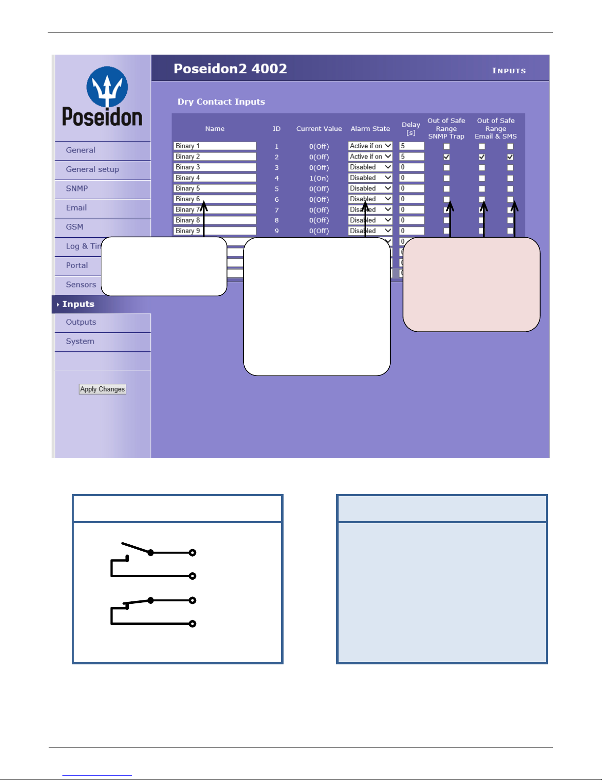
Inputs
Parameters for Dry Contact inputs.
Name – Name of the input, up to 12 chars (e.g. “left door”, “smoke room 1”).
ID – Unique ID of the input variable within the device [1..32]
Current Value – Current state of the input (“0 (Off)” / “1 (On)“)
Alarm State – Alarm state definition for each input
Active if On – Alarm is active whenever the input is in 1 (On)
Active if Off – Alarm is active whenever the input is in 0 (Off)
Disabled – Input has no alarm state defined
Page 55

Poseidon2 – Family manual
HW group
www.HW-group.com
55 / 104
Delay [s]
Delays the
information about
alarm beginning
and alarm end.
Out of Safe Range
Reaction to activation/deactivation of the alarm state for dry contact inputs
SNMP Trap – Enables sending a SNMP trap upon alarm activation/deactivation
Email – Enables sending an e-mail upon alarm activation/deactivation
SMS – Enables sending an SMS upon alarm activation/deactivation
Note: SMS (text messages) are sent through a GSM modem connected directly to the
Poseidon unit via the RS-232 interface. See the list of Poseidon models for
details.
Page 56

Poseidon2 – Family manual
HW group
www.HW-group.com
56 / 104
Outputs
Control and mode configuration of outputs.
ID – Unique ID of the output within the device [151..215]
Name – Name of the output, up to 12 chars (e.g. “top fan”, “Door rack 4”).
Current Value – Current state of the input (“0 (Off)” / “1 (On)“)
ON (Closed) Name – State 1 name (On) - for example set, flooded, closed, etc.
ON (Closed) Name – State 0 name (Off) - for example disconnected, open, etc.
Pulse timer – Allows switching the output to the state 1 (On) for a defined time.
If you need the opposite polarity, use the NO/NC relay output.
With Pulse Timer = 0, the pulse function on the output is inactive (default value)
Switching the output for a defined time apply also for local condition mode. Pulse time starts
when the condition is triggered (Safe Range is exceeded) Switches only once after the
condition is met.
Page 57

Poseidon2 – Family manual
HW group
www.HW-group.com
57 / 104
Output Control
Manual – Output controlled over the web or M2M protocols (XML, SNMP..)
Change to On / Off – Change output state (after confirming with Apply
Changes)
Local Condition – Output is controlled by the sensor state condition.
For M2M protocols the output value is for reading only (output cannot be controlled).
Output is controlled by the Target Value, hysteresis (IDLE Range) set for the specific
sensor is used.
On if any alarm
The output is closed if at least one of the inputs or sensors is in alarm.
This condition accepts also DELAY and HYSTERESIS settings of the specific
active sensors and inputs.
On if alarm on
This output switches if an Alarm occurs on a specific selected sensor (input).
On if value equal to Trigger
The output is closed if the value matches the Target Value setting.
On if value higher than Trigger
The output is closed if the Current Value is greater than the Target Value
setting.
On if value Lower than Trigger
The output is closed if the Current Value is lower than the Target Value setting
Trigger Value – Border value of the condition
(This output switches On for example if the value is higher than the Trigger Value)
Dependent On – Selection of a sensor to which the condition applies.
Note: Output conditions are not supported on Poseidon 2250.
Local conditions are also called IP Thermostat mode.
Page 58

Poseidon2 – Family manual
HW group
www.HW-group.com
58 / 104
GSM modem (local or remote)
Text messages (SMS) can be sent in two ways:
A) Local GSM modem
A GSM modem is connected to the Poseidon's RS-232 interface. The modem is powered from its
own adapter or from the 12V power out. An active SIM is inserted in the modem, PIN is disabled.
SMS Center should be retrieved from the SIM after start-up.
B) Remote GSM modem
Poseidon does not have its own GSM modem. “Serial Port Settings” is set to “Disabled”. To send a
SMS, a GSM modem connected to another Poseidon unit or the “SMS GW” product is used. Remote
GSM modem has to be accessible online, via „service.xml,“ using address A, usually on port 80
SOAP protocol is used for communication. If the connection is not established or is refused,
Poseidon tries to send the SMS again.
The throughput of the remote GSM modem is limited to 5 SMS per minute for Poseidon units and about
20 SMS per minute for “SMS GW”.
The modem function can be tested by pressing the corresponding button.
The SMS + Ring When Alarm option rings the telephone number for 4 seconds after sending the alarm
SMS.
Select local or remote
GSM modem.
Address of the
remote GSM
modem (SMS GW).
Alert SMS (rings)
will be delivered to
these phone
numbers.
Select Disabled when you
want to use remote GSM
modem.
Select GSM Modem to use
a local modem.
Page 59

Poseidon2 – Family manual
HW group
www.HW-group.com
59 / 104
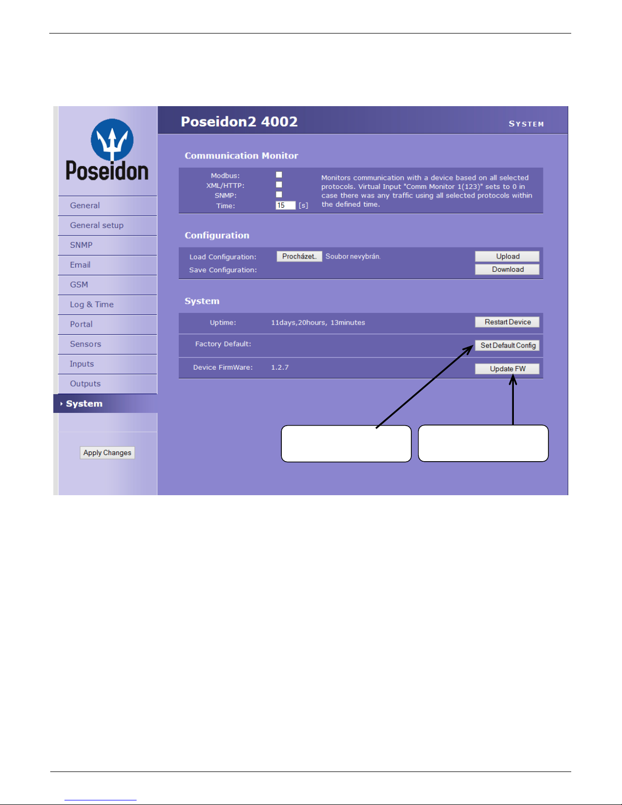
System
Communication monitor
Monitors communication with the Poseidon over selected protocol. If the communication stops for longer
than the set time, virtual input Comm monitor is triggered.
Save Configuration – Stores the setup.xml file with device configuration to your HDD.
Load Configuration – Loads a XML file with the configuration from your PC.
Uptime – Time of uninterrupted device operation (since last restart)
Check for firmware updates
Online check if a newer firmware version is available at the HW group server.
Set Default Config – Restore factory-default settings.
Restart device – resets the unit
Update FW - Loads a .HWg firmware file from your PC to the device.
Page 60

Poseidon2 – Family manual
HW group
www.HW-group.com
60 / 104
Update Firmware
Updating the firmware over the WEB
Upload the firmware in a .hwg file over HTTP to http://x.x.x.x/upload/.
Connection cannot be interrupted during
the transmission. If the FW is not loaded
correctly this way, use the previously
mentioned RS-232 update option to
upload the file.
Firmware in the .HWg format is available
at the Poseidon website, or on the
supplied CD.
Firmware Update over RS-232
Poseidon2 4002 firmware can be updated via RS-232 interface. The firmware consists of a single file
with a .HWg extension. You can download the file at our website.
Caution: Please contact us in case of any problems with firmware upload.
Poseidon Firmware Upload – step by step
Power off the Poseidon.
Connect the Poseidon2 to the serial
port on your PC using a RS-232
cable with the “Laplink” wiring.
Set the Poseidon2 DIP switches to:
DIP1=ON, DIP2=OFF, DIP3=OFF,
DIP4=OFF.
Run the Hercules Setup utility and
select the “Serial” tab.
Select the serial port where the
Poseidon2 is connected.
Click the “HWg FW update” option
and select the firmware file you
want to upload to the Poseidon2.
When the screen with the progress
bar appears, power the Poseidon2
back on.
After uploading the firmware, previous configuration settings are retained. The Poseidon2
restarts and is immediately operational.
Remember to return the DIP switches to their previous positions.
Page 61

Poseidon2 – Family manual
HW group
www.HW-group.com
61 / 104
Software Applications
HWg-PDMS
Windows application that logs
data from all HW group devices
into its internal database.
The application runs in the
background (NTservice). Data are
retrieved from the device over
HTTP or e-mail.
Data can be exported over XML
or automatically stored to MS
Excel.
License: Free HWg-PDMS version for 3 sensors
Paid versions for 8 / 20 / 200 / unlimited sensors
HWg-Trigger
Windows application for detecting and reacting
to events.
Detects, for instance, disconnected devices,
failed sensors values out of range, or incoming
SNMP Trap alerts.
Possible responses include sending an
e-mail, activating a relay over the
network, or sending a text message
(SMS) using HWg-SMS-GW.
Other responses include displaying a
warning message in Windows,
starting an application, or shutting down
the computer.
License: 30-day trial version free of charge
Page 62

Poseidon2 – Family manual
HW group
www.HW-group.com
62 / 104
PosDamIO
Poseidon Damocles I/O is a command-line utility for Windows and Linux that lets
you control Poseidon and Damocles units over the XML interface. Calling the
program can print out the sensors, inputs and outputs states, but also set an output
to a log. 1 or 0.
SensDesk.com
Online portal for collecting data from LAN and GSM sensors.
Poseidon2 can connect to the SensDesk Internet service. All devices can be managed from a single
WWW interface. Watch sensor states, display your devices in a map, compare trends in time and
analyze alarm messages.
SensDesk is a way to implement fully functional monitoring of customer technology in a matter of
minutes, with fixed costs of the system. No need for installing a complex system or adding another
server at the customer side.
Overview of all sensors at a single place
Centralized alarm configuration for individual sensors
Mobile application for monitoring
Remote configuration of GSM devices
Page 63

Poseidon2 – Family manual
HW group
www.HW-group.com
63 / 104
www.SensDesk.com
Connecting Poseidon2 to SensDesk portal
Connecting to the portal
1) Connect the device to a computer network and set the network parameters (More in First steps
chapter in the user manual).
2) Go to the device's WWW setup, Portal tab, in the Portal Config section tick the Portal field,
save the changes and then press the Manual Push button. Standard procedure:
http://sensdesk.com/portal.php
>> Click the message in “Portal message” section.
Page 64

Poseidon2 – Family manual
HW group
www.HW-group.com
64 / 104
Page 65

Poseidon2 – Family manual
HW group
www.HW-group.com
65 / 104
3) By clicking the SensDesk.com: register your IP sensor link you will be redirected to the
SensDesk.com service website - to a login dialog.
4) If you already have a user account, enter the
login details and the device will be
automatically assigned to your account.
Otherwise click the Register to Portal link to
get to the registration form.
5) Create the login details. E-mail address has
to be unique for the whole portal.
Company name field allows you to create a 3rd level domain (typically
company.sensdesk.com). If you leave this field empty, a
user name will be used for the sub domain.
A user account will be created after clicking the Create
new account button and at the same time an activation email will be sent to your e-mail address. A links sent to
your e-mail address has to be used in order to activate the
account.
Page 66

Poseidon2 – Family manual
HW group
www.HW-group.com
66 / 104
6) Account activation will redirect you to an Invitation page.
Test the portal reaction to your devices. After
leaving the page the reaction time to changes in
measured values will increase to 15 minutes. In
case a shorter time is needed, set the "AutoPush"
parameters in the device's setup.
7) Device Password can be found in the user account options on SensDesk.com (My Account),
in the field Push.
This password is saved in devices and mobile
applications. Device password cannot be changed
and for security reasons it is different to your user
password.
8) Mobile phone app: SensDesk Mobile
In the account configuration settings on SensDesk.com are instructions how to download the
mobile application for free.
Page 67

Poseidon2 – Family manual
HW group
www.HW-group.com
67 / 104
Using Poseidon2 units in your applications
PosDamIO – Command line control
Poseidon Damocles I/O is a command-line utility for Windows and Linux that lets you control
Poseidon and Damocles units over the XML interface. Calling the program can print out the
sensors, inputs and outputs states, but also set an output to a log. 1 or 0.
The PosDamIO utility is intended for applications and scripts that need a simple way of controlling or
reading remote sensors, digital inputs and digital outputs. You can modify the utility to suit your needs
– it is included in the HWg SDK.
Basic functions
Dump the states of sensors, digital
inputs and outputs to the screen, or
to a file
Set the state of an output with a
command-line command
Read the state of an input and set
the ErrorLevel return value
accordingly
Download or upload the values.xml
file containing the current readings
Download or upload the setup.xml
file containing device configuration
for easy device cloning
Features
Windows and Linux version
Source code included in the HWg
SDK
All communication with the device
takes place over the XML interface
Before uploading, the utility transforms the XML file to the format required by the
device (see product manual)
Conclusion:
PosDamIO is a free command-line utility that enables simple control of Poseidon units from within
batch files. Its source code is freely available in the HWg SDK package.
For detailed information, see: AN29: PosDamIO controls outputs through the command line.
Page 68

Poseidon2 – Family manual
HW group
www.HW-group.com
68 / 104
HWg-SDK
HWg SDK is a library of functions, as well as examples of their use, for Unix and Windows. The
functions are intended to help third-party SW solutions communicate with our products over IP. SDK
reduces the time needed to implement support for our products into your SW.
HWg SDK is free of charge; however, you need to register before downloading. After
competing the registration you will receive a link to the latest version download.
http://www.hw-group.com/software/sdk/index_en.html
HWg SDK is available in English only.
SDK installs to the Windows environment, its interface is HTML-based.
When is the SDK useful for you? For example, Poseidon products share the readings in a welldocumented XML file. A simple XML parser is sufficient to transform the data into another structure.
However, to receive alarm alerts, a SNMP trap parser needs to be implemented, and so on.
All of these functions use standard interfaces. On the other hand, unless you already have a
complete SNMP implementation in your software, it is easier to use HWg SDK functions that invoke
the respective event handlers in your software.
Basic SDK features
HWg SDK is simple to understand
HWg SDK speeds up the implementation of HW group products in your SW
With HWg SDK, you don’t have to worry about future changes of structures, interface
updates, and so on
HWg SDK is ready to work with most programming languages
Structure according to the programming language
Visual Basic (6.0) (all 3xx examples)
Borland C++ (all 1xx examples)
Delphi (all 4xx examples)
Microsoft Visual C++ (all 2xx examples)
.NET (all 5xx examples)
other examples that do not directly use SDK functions (all 9xx examples)
Page 69

Poseidon2 – Family manual
HW group
www.HW-group.com
69 / 104
Examples of HWg-SDK contents
Ready-made examples of functioning, complete programs that can be reused
Documented functions, examples of use
Caution: The entire SDK is commented in English only. Therefore, the description that
follows is in English only.
Ready-made examples in HWg SDK (for Borland C++ builder)
EX101: UDP setup
Simple application to handle UDP setup functions in Borland C++
Builder using the HWg SDK. Includes searching for devices as
well as reading and writing their basic network parameters.
Functions used: hwudps_init, hwudps_uninit, hwudps_reinit,
hwudps_search, hwudps_search_finish, hwudps_count,
hwudps_record, hwudps_setup, hwudps_setup_finish
EX102: I/O Controller example
Simple example to demonstrate UDP search for devices,
reading and writing basic network parameters and controlling
I/O pins of the I/O Controller device. Written in Borland C++
Builder using the HWg SDK. I/O pins are controlled with NVT
commands based on a RFC2217 extension by HW group.
Functions used: hwudps_init, hwudps_uninit, hwudps_reinit,
hwudps_search, hwudps_search_finish, hwudps_count,
hwudps_record, hwudps_setup, hwudps_setup_finish,
hwnvt_init, hwnvt_uninit, hwnvt_open, hwnvt_close,
hwnvt_open_finish, hwnvt_clr_callback_struct,
hwnvt_in_change2callback, hwnvt_get_in,
hwnvt_wait_finish, hwnvt_get_in_cache, hwnvt_get_out,
hwnvt_get_out_cache, hwnvt_set_out_pin
Demonstrated features
UDP broadcast search for devices
Displaying discovered devices
Editing the parameters for a specified MAC address
Applying changes to a specified device
Reading the state of 8 input bits
Writing the state to the output register (bit by bit)
Using a callback function to quickly detect changes at input pins
EX103: Remote serial port control
An example to demonstrate UDP search for devices, reading and writing basic network
parameters and controlling the parameters of a remote serial port. Communication with the
remote device, reading and writing data over a TCP connection. Written in Borland C++
Builder using the HWg SDK. Serial port settings are controlled with NVT commands based
on a RFC2217 extension by HW group.
Page 70

Poseidon2 – Family manual
HW group
www.HW-group.com
70 / 104
EX104: XML file downloader XML A
An example to demonstrate UDP search for devices,
reading their basic network parameters, and
downloading and parsing the XML file with sensor and
binary input states. Values can be downloaded from
one device only at a time. Written in Borland C++
Builder using the HWg SDK.
Functions used: hwudps_init, hwudps_uninit,
hwudps_reinit, hwudps_search,
hwudps_search_finish, hwudps_count,
hwudps_record, hwxml_init, hwxml_uninit,
hwxml_open, hwxml_close, hwxml_get_values,
hwxml_get_values_cache, hwxml_finish
Demonstrated features
UDP broadcast search for devices
Displaying discovered devices and selecting five of them
Downloading the XML file with readings via the HTTP protocol and parsing it
Storing all values from a device into a table
Downloading the readings manually or automatically every XX seconds
All errors are logged to the log window
EX105: XML file downloader XML B
An application to demonstrate UDP search for devices, reading basic network parameters,
and downloading and parsing the XML file with sensor and binary input states. Readings can
be downloaded from up to five devices at a time. Written in Borland C++ Builder using the
HWg SDK.
Functions used: hwudps_init, hwudps_uninit, hwudps_reinit, hwudps_search,
hwudps_search_finish, hwudps_count, hwudps_record, hwxml_init, hwxml_uninit,
hwxml_open, hwxml_close, hwxml_get_values,
hwxml_get_values_cache_many, hwxml_count_modules, hwxml_finish
EX106: SNMP traps receiver
An application to demonstrate UDP search for
devices, reading basic network parameters, and
downloading and parsing the XML file with
sensor and binary input states. Readings can be
downloaded from up to five devices at a time.
Written in Borland C++ Builder using the HWg
SDK.
Functions used: hwxml_init, hwxml_uninit,
hwxml_open, hwxml_close,
hwxml_get_values, hwxml_get_values_cache,
hwxml_finish, hwxml_error, hwsnmp_init,
hwsnmp_uninit, hwsnmp_trap_recv_create,
hwsnmp_trap_recv_create_finish,
hwsnmp_clr_traps_callback,
hwsnmp_traps2callback
Page 71

Poseidon2 – Family manual
HW group
www.HW-group.com
71 / 104
Demonstrated features
Receiving traps from multiple devices at a time
Support for Poseidon and Damocles family
Parsing known traps and writing them to the log
Downloading detailed information about all sensors from a specified device
EX109: Polling data
The application shows how to search for
a device on the local network and add
the device to the “device list”. Sensor
readings are downloaded periodically
from all devices in this list. All readings
from all devices are shown in a single
sensor list. Written in Borland C++
Builder using the HWg SDK.
Functions used: SearchDevice,
SearchDone, GetDeviceList,
AddToDeviceList, ClearDeviceList,
CreatePolling, GetNowPolling,
DestroyPolling, LockPolling, UnlockPolling
Demonstrated features
Using the PosDamInstWiz.dll high-level library
Support for Poseidon and Damocles products
Using the Installation Wizard
Storing all values from all devices into one large shared table
Setting the digital outputs
Setting the safe range thresholds for analog sensors
EX110: Setting outputs
The application shows how to use the
Installation Wizard to add a device to the host
application. All sensors and digital
inputs/outputs are shown in a single sensor list.
It is shown how to change values of digital
outputs and sensor safe ranges. Written in
Borland C++ Builder using the HWg SDK.
Functions used: InstWiz_Show, InstWiz_GetDevice,
InstWiz_FirstDevice, InstWiz_AddDevice, InstWiz_RemoveDevice, InstWiz_Clear,
AddToDeviceList, ClearDeviceList, CreatePolling, DestroyPolling, GetNowPolling,
LockPolling, UnlockPolling, SetBinaryOutput, SetSensorRange
Demonstrated features
Using the PosDamInstWiz.dll high-level library
Support for Poseidon and Damocles products
Using the Installation Wizard
Page 72

Poseidon2 – Family manual
HW group
www.HW-group.com
72 / 104
Storing all values from all devices into one large shared table
Setting the digital outputs
Setting the safe range thresholds for analog sensors
EX111: Simple Setting of Outputs
A very simple application shows how to change the values of
digital outputs. Written in Borland C++ Builder using the HWg
SDK.
Functions used: SetBinaryOutput
Demonstrated features
Using the PosDamSDK.dll high-level library
Support for Poseidon and Damocles products
Setting the digital outputs
No HTTP authentication support
EX112: Setting Outputs, Non-blocking
The application shows how to change the values of digital outputs.
It shows how to create a non-blocking application that does not
“freeze” the graphical user interface. HTTP authentication is
supported for access to the device. Written in Borland C++ Builder
using the HWg SDK.
Functions used: hwxml_init, hwxml_uninit, hwxml_open,
hwxml_close, hwxml_authenticate_set, hwxml_clr_callback, hwxml_callback,
hwxml_send_setup_xml, hwxml_finish, hwxml_get_setup_cache
Demonstrated features
Support for Poseidon and Damocles products
Setting the digital outputs
HTTP authentication support
Non-blocking graphical user interface (GUI)
EX113: Device Config
The application shows how to change the configuration of WEB51-based devices through
TCP setup. Quiet mode of TCP Setup is used. Written in Borland C++ Builder using the HWg
SDK.
Page 73

Poseidon2 – Family manual
HW group
www.HW-group.com
73 / 104
EX115: Poseidon & Damocles I/O
The PosDamIO utility is designed for batch
scripts and applications that need to easily
control or log remote sensors, digital inputs
and outputs. It is written in C and compiled
in Borland C++ Builder using the HWg SDK.
Demonstrated features
Displaying a list with sensor states,
digital inputs and outputs on the
screen, or recording it to a file
Setting an output using the command line
Reading the state of an input and setting ErrorLevel according to the returned value
Downloading and uploading the values.xml file
Downloading/uploading the setup.xml configuration file of the device – easy device
cloning
Page 74

Poseidon2 – Family manual
HW group
www.HW-group.com
74 / 104
Documentation for programmers
Generated automatically using the Doxygen system
Opens after SDK installation or by clicking HW group SDK > HWg SDK main page
Conclusion:
Register and download the current SDK version on the page:
http://www.hw-group.com/
Page 75

Poseidon2 – Family manual
HW group
www.HW-group.com
75 / 104
Poseidon formats and interfaces
SMS – Interface description
SMS format
DEVICE_NAME #ALARM SENSOR1_NAME:VALUE/EXCEEDED_THRESHOLD
SENSOR1_NAME:VALUE/EXCEEDED_THRESHOLD #STATUS: INP: 0 0 0
SENS:VALUES_OF_ALL_SENSORS_CONNECTED_TO_UNIT
Description:
Values are separated with spaces
DEVICE_NAME is truncated to a maximum of 8 characters
SENSOR1 _NAME is truncated to a maximum of 6 characters
Values are only positive or negative integers – no decimal separators
The list always shows all sensors, including those in alarm
Temperature is displayed in the following format: 48C
Humidity is displayed in the following format: 10%.
SMS example:
Device name: Poseid11
Sensors in Alarm:
Rack11 = 48.5°C, threshold is 40°C
T-Room = 48.3°C, threshold is 35°C
H-Room = 10% RH, threshold is 45% RH
Poseid11 ALARM: Rack11(48),T-Room(48),H-Room(10)
Page 76

Poseidon2 – Family manual
HW group
www.HW-group.com
76 / 104
E-mail – Interface description
<---------------------------61----------------------------->
<---10---> <---8--> <------16------> <------15----->
<-5-> <------15-----> <---11 ---> <------16------> <--8--->
DATE TIME Device_NAME Device_IP
XX.XX.XXXX XX:XX:XX XXXXXXXXXXXXXXXX XXX.XXX.XXX.XXX
|-1
Email initiated: XXXXX XXXXXXXXXXXXXXX XXXXXXXXXXXXXXX
|-1
-----------------------------------------------------------ID SENSOR_Name VALUE UNIT Safe_RANGE ALARM
-----------------------------------------------------------|-1
ALARM state:
------------------------------------------------------XXXXX XXXXXXXXXXXXXXX XXXX.XX XXX XXXX.X .. XXXX.X XXXXXXXX
|
|-2
Sensors list:
-------------------------------------------------XXXXX XXXXXXXXXXXXXXX XXXX.XX XXX XXXX.X .. XXXX.X XXXXXXXX
XXXXX XXXXXXXXXXXXXXX XXXX.XX XXX XXXX.X .. XXXX.X XXXXXXXX
XXXXX XXXXXXXXXXXXXXX XXXX.XX XXX XXXX.X .. XXXX.X XXXXXXXX
|
|-2
-----------------------------------------------------------Device_NAME: http://Device_IP 00:0A:59:xx:xx:xx
------------------------------------------------------------
Description
When a sensor is not available (disconnected, not found), “-999.99” is shown
All texts that exceed the reserved length are truncated
Device name is 16 characters long, sensor names are 15 chars long
Readings are listed with two decimal places, safe range thresholds with one
All numbers in e-mails and logs use a period as the decimal separator.
Besides Alarm, the reason for sending the e-mail can also be “Periodical report”
Page 77

Poseidon2 – Family manual
HW group
www.HW-group.com
77 / 104
E-mail subject:
The following strings are appended to the specified e-mail subject:
“Test” for the test e-mail
“Periodical report” for the periodically e-mailed report
“T-Room Alarm ACTIVATED” when the alarm for the sensor named T-Room is activated
“T-Room Alarm DEACTIVATED” when the alarm for the sensor named T-Room is
deactivated
Alarm activation:
DATE TIME Device_NAME Device_IP
10.10.2005 15:04:27 Server_room1 192.168.1.20
Email initiated: 48245 T-Room Alarm ACTIVATED
-----------------------------------------------------------ID SENSOR_Name VALUE UNIT Safe_RANGE ALARM
------------------------------------------------------------
ALARM state:
------------------------------------------------------48245 T-Room 25.30 °C -45.0 .. 22.0 Enabled
1 C-water OFF if OFF
Sensors list:
-------------------------------------------------48245 T-Room 25.30 °C -45.0 .. 22.0 Enabled
1559 H-Room 53.00 %RH 30.0 .. 80.0 Enabled
48 T-Srv01 -27.30 °C -49.0 .. –25.1 Disabled
257 ABCDEFGHIJKLMNO -109.30 °C -150.0 .. -105.0 Enabled
1 C-water OFF if OFF
2 C-AirFl OFF if ON
3 C-Door1 OFF Disabled
-----------------------------------------------------------Server_room1: http://192.168.1.20 00:0A:59:00:00:00
------------------------------------------------------------
Page 78

Poseidon2 – Family manual
HW group
www.HW-group.com
78 / 104
Alarm deactivation:
DATE TIME Device_NAME Device_IP
10.10.2005 15:04:27 Server_room1 192.168.1.20
Email initiated: 48245 T-Room Alarm DEACTIVATED
-----------------------------------------------------------ID SENSOR_Name VALUE UNIT Safe_RANGE ALARM
------------------------------------------------------------
ALARM state:
------------------------------------------------------ 1 C-water OFF if OFF
Sensors list:
-------------------------------------------------48245 T-Room 21.30 °C -45.0 .. 22.0 Enabled
1559 H-Room 53.00 %RH 30.0 .. 80.0 Enabled
48 T-Srv01 -27.30 °C -49.0 .. –25.1 Disabled
257 ABCDEFGHIJKLMNO -109.30 °C -150.0 .. -105.0 Enabled
1 C-water OFF if OFF
2 C-AirFl OFF if ON
3 C-Door1 OFF Disabled
-----------------------------------------------------------Server_room1: http://192.168.1.20 00:0A:59:00:00:00
------------------------------------------------------------
Periodical e-mail:
DATE TIME Device_NAME Device_IP
10.10.2005 15:04:27 Server_room1 192.168.1.20
Email initiated: Periodical report
-----------------------------------------------------------ID SENSOR_Name VALUE UNIT Safe_RANGE ALARM
------------------------------------------------------------
ALARM state:
------------------------------------------------------ 1 C-water OFF if OFF
Sensors list:
-------------------------------------------------48245 T-Room 21.30 °C -45.0 .. 22.0 Enabled
1559 H-Room 53.00 %RH 30.0 .. 80.0 Enabled
48 T-Srv01 -27.30 °C -49.0 .. –25.1 Disabled
257 ABCDEFGHIJKLMNO -109.30 °C -150.0 .. -105.0 Enabled
1 C-water OFF if OFF
2 C-AirFl OFF if ON
3 C-Door1 OFF Disabled
-----------------------------------------------------------Server_room1: http://192.168.1.20 00:0A:59:00:00:00
------------------------------------------------------------
Page 79

Poseidon2 – Family manual
HW group
www.HW-group.com
79 / 104
XML – Interface description
Poseidon supports the following XML files:
values.xml
Small file for periodical polling of sensor readings. Subset of setup.xml – only basic
identification and sensor readings are included.
setup.xml
Complete device configuration
Reading values using XML
Sensor readings are available as a HTML page intended for human users and as a XML page
(values.xml). Any application can easily read the values from XML tags.
XML record example for a temperature sensor:
<Entry>
<Name>Sensor 16</Name> - Sensor name
<Interface>RS485</Interface> - Sensor interface
<ID>75</ID> - Unique identification within the device
<Value>27.8</Value> - Current temperature, string with a
decimal point, without measure
<Min>10.0</Min> - Lower alarm limit, string with a decimal
point, without measure
<Max>50.0</Max> - Upper alarm limit, string with a decimal
point, without measure
<Hyst>0.0</Hyst> - Hysteresis range, string with a decimal
point, without measure
<SNMPTrap>1</SNMPTrap> - SNMP Trap, 0 = off, 1 = on
<EmailSMS>0</EmailSMS> - E-mail, SMS, 0 = off, 1 = on
<AlarmState>Active</AlarmState> - Alarm, Active or Inactive
<Color>0</Color> - Line color, shows state of a sensor in
this line.
<UnitType>C</UnitType>
</Entry>
Note: You can back up your device configuration by downloading the setup.xml file.
Writing values to the device using XML
The setup.xml and values.xml files can be uploaded to the Poseidon unit, if allowed by the protective
measures (HTTP password, IP address filter, DIP switch setting).
For downloading or uploading XML files from/to the Poseidon unit, we recommend the utility attached
to Application Note 29: AN29: PosDamIO controls outputs through the command line
Page 80

Poseidon2 – Family manual
HW group
www.HW-group.com
80 / 104
Setup.xml format – version 2.37
Release notes for the actual version can be always found at http://new.hwg.cz/cs/node/4561
Information Section
<Agent> - Read only device parameters group
<Version>1.1.12</Version> - Device firmware version (Read only)
<XmlVer>2.37</XmlVer> - XML file version (Read only)
<DeviceName>Poseidon in kitchen</DeviceName> - Device name – User configurable, Identical with <SysName> value, here read
only (64 chars)
(Here read only, change in <Network> part of XML)
<Features> - Basic features of the device
<RS485/>
<Wire1/>
<BinaryIn/>
<BinaryOut/>
<CommMonitor/>
<DHCP/>
<SNTP/>
<SNMP/>
<SMTP/>
<Modbus/>
<GSM/>
<DataLogger/>
<Report/>
<Telnet/>
<SOAP/>
<WSDL/>
<ValuesReport/>
<AlarmReminder/>
<Portal/>
</Features>
<Model>34</Model> - Technical device type – available also over UDP Setup (5 chars)
<VendorID>10</VendorID> - Vendor ID number – 0 .. 65565 16. bit number in ASCII
<MAC>00:0A:59:03:0C:91</MAC> - Unique device MAC address
<Uptime>564620</Uptime> - Total running time since last restart
<Title>Poseidon model 1250</Title> - Customizable device title – Top of the HTML page (Read only),
Marketing device name (more in customization) (max 32 chars)
<Contact>Information: www.HW-group.com</Contact> - User definable contact message, HTML code support (max 254 chars)
(Read only here, can be updated over TCP setup only, more in customization)
</Agent>
<CommMonitor> - Communication Monitor
<Modbus>0</Modbus> - Modbus monitoring (0/1)
<XML_HTTP>0</XML_HTTP> - XML monitoring (0/1)
<SNMP>0</SNMP> - SNMP monitoring (0/1)
<Timeout>0</Timeout> - Period of Communication Monitor (in seconds)
</CommMonitor>
Page 81

Poseidon2 – Family manual
HW group
www.HW-group.com
81 / 104
Input, Output and Sensor Section
<BinaryInSet> - Binary dry contact inputs (next only “Binary input”)
<Entry>
<ID>1</ID> - Entry identification, ID (1..64), source for <CondInputID> for output control, ID in
unique per device, 1..64 are reserved for binary inputs
<Name>Binary 1</Name> - Defined name of the input (text string, 20 chars)
<Value>0</Value> - Current value 0/1 (Read only)
<Alarm>0</Alarm> - alarm settings for this Binary input – 1 byte 0 = active if on, 1 = active if off, 2 =
inactive
<Delay>0</Delay> - 0..255 Time delay in seconds to prolong Alarm state reaction. (used for Alarm Start even
for Alarm End reaction)
Similar to Hysteresis but in seconds.
<State>0</State> - Current sensor state 0 = normal, 1 = Alarm activated but not send (Alarm sending
Email or Trap not activated), 2 = alarm activated
<SNMPTrap>0</SNMPTrap> - SNMP Trap alarm enable 0 = don't send, 1 = send if value out of SafeRange
<Email>0</Email> - E-mail alarm enable 0 = don't send, 1 = send if value out of SafeRange
<SMS>0</SMS> - SMS alarm enable 0 = don't send, 1 = send if value out of SafeRange
<ApDelta>0</ ApDelta> - AutoPush is a function allowing sending of measured data in case of value
increase/decrease larger than AutoPush delta parameter.
</Entry>
<Entry>
<ID>2</ID> - Binary input 2
<Name>Binary 2</Name>
<Number>I2</Number>
<Value>0</Value>
<Alarm>2</Alarm>
<Delay>0</Delay>
<State>0</State>
<SNMPTrap>0</SNMPTrap>
<Email>0</Email>
<SMS>0</SMS>
<ApDelta>0</ ApDelta>
</Entry>
<Entry>
<ID>3</ID> - Binary input 3
<Name>Binary 3</Name>
<Number>I3</Number>
<Value>0</Value>
<Alarm>2</Alarm>
<Delay>0</Delay>
<State>0</State>
<SNMPTrap>0</SNMPTrap>
<Email>0</Email>
<SMS>0</SMS>
<ApDelta>0</ ApDelta>
</Entry>
</BinaryInSet>
<BinaryOutSet> - Binary outputs settings & values
<Entry>
<ID>151</ID> - Entry identification, ID (151..214), source for <CondInputID>, ID in unique per
device,
151..200 are reserved for outputs
<Name>RTS</Name> - Output name (Read only)
<Type>1</Type> - Type of the binary outputs
0: X/Y = “On” / “Off” (Relay output),
1: X/Y = “On (+10V)” / “Off (-10V)” (RTS output)
2: X/Y = “On (+10V)” / “Off (0V)” (DTR output)
<Mode>0</Mode> Output control mode (Manual / Local + condition)
0 = Manual output control (value defined by Value tag)
1 = Local output control (On if any alarm)
2 = Local output control (On if value equal to Trigger)
3 = Local output control (On if value higher than Trigger)
4 = Local output control (On if value lower than Trigger)
5 = Local output control (On if Alarm on)
<Value>0</Value> - 0/1 Current output value
0 = Y (“Off” / “Off (-10V)” / “Off (0V)”)
1 = X (“On” / “On (+10V)” / “On (+10V)”)
R/W for the „Manual output control”
R for the „Local output control” (On if any alarm)
<CondInputID>74</CondInputID> - Condition related input ID – Poseidon 3268 future
<Trigger>-18.5</Trigger > - Trigger value for condition – Poseidon 3268 future
</Entry>
Page 82

Poseidon2 – Family manual
HW group
www.HW-group.com
82 / 104
<Entry>
<ID>152</ID> - Entry identification
<Name>DTR</Name>
<Type>2</Type>
<Value>0</Value>
<Mode>3</Mode>
<CondInputID>75</CondInputID>
<Trigger>22.5</Trigger >
</Entry>
</BinaryOutSet>
<SenSet> - All detected sensors
<Entry>
<ID>57856</ID> - Entry identification, ID address of the sensor (Read only), source for
<CondInputID>, ID in unique per device,
48..122 and 256..65535 are reserved for sensors
<SensId>57856</SensId> - Full 1-Wire ID address of the sensor (Read only), 1-Wire ID is unique. 1-Wire
sensors only
<Name>Sensor 240</Name> - Defined name of the sensor (text string, 15 chars)
<Units>C</Units> - Unit of send value "C" for temperature,
"%RH" for humidity, "V" for voltage "mA" for current
“s” for Switch (0/1) “p” for counter pulses (1/10 digit can be used)
etc...
<Value>23.0</Value> - Current value, one decimal value, decimal separator is “.” (Read only)
<Calib>-0.15</Calib> - Sensors calibration shift value (Value = Raw sensor value + Calib)
Not implemented yet - ready to use in the future
<Min>-1.5</Min> - SafeRange minimal limit
<Max>24.6</Max> - SafeRange maximal limit
<Hyst>0.0</Hyst> - Hysteresis (non sensitivity range) value
<SNMPTrap>1</SNMPTrap> - SNMP trap alarm enable 0 = don't send, 1 = send if value out of SafeRange
<Email>0</Email> - E-mail alarm enable 0 = don't send, 1 = send if value out of SafeRange
<SMS>0</SMS> - SMS alarm enable 0 = don't send, 1 = send if value out of SafeRange
<Delay>0</ Delay> - 0..255 Time delay in seconds to prolong Alarm state reaction. (used for Alarm Start even
for Alarm End reaction)
Similar to Hysteresis but in time
<ApDelta>0</ ApDelta> - AutoPush is a function allowing sending of measured data in case of value
increase/decrease larger than AutoPush delta parameter.
<State>0</State> - Current sensor state
0 = normal, 1 = Alarm activated (value out of SafeRange) but not send (Alarm
sending by Email or Trap not activated),
2 = value out of SafeRange - Alarm sent, 4 = sensor invalid (not connected)
</Entry>
<Entry>
<ID>74</ID>
<Code>74</Code>
<Name>Sensor 23</Name>
<Units>C</Units>
<Value>23.8</Value>
<Calib>0.19</Calib>
<Min>10.0</Min>
<Max>60.0</Max>
<Hyst>0.0</Hyst>
<SNMPTrap>0</SNMPTrap>
<EmailSMS>0</EmailSMS>
<ApDelta>0</ ApDelta>
<State>0</State>
</Entry>
</SenSet>
Page 83

Poseidon2 – Family manual
HW group
www.HW-group.com
83 / 104
RS-232/GSM Settings
<SerialPort>
<E>1</E> - Enable Serial Port 0= Disabled, 1=GSM modem, 2=RFID reader
</SerialPort>
<SMS>
<Function>0</Function> - Function 0-Local Modem, 1=Remote GSM GW
<Ring>0</Ring> - Enable Ring alert (0/1)
<Dest>1</Dest> - Remote SOAP GW destination number
<Module>Not enabled</Module> - FOUND / NOT FOUND of GSM serial terminal
<CenterNmr/> - SMS center Number
<Recp1/> - SMS1 destination Number
<Recp2/> - SMS2 destination Number
<Recp3/> - SMS2 destination Number
<Recp4/> - SMS2 destination Number
<Recp5/> - SMS2 destination Number
<State>0</State> - Test processing report
<Message/> - SMS Test report message from last SMS test
</SMS>
Destination Section
<SnmpTraps> - SNMP Traps settings
<Entry>
<Idx>1</Idx> - Entry identification
<Community>public</Community> - SNMP Community settings (32 chars)
<IPaddr>192.168.1.39</IPaddr> - SNMP trap destination IP address
<Port>162</Port> - SNMP trap destination port
<E>1</E> - Enable / Disable destination (0/1)
</Entry>
<Entry>
<Idx>2</Idx>
<Community></Community>
<IPaddr></IPaddr>
<Port></Port>
<E>0</E>
</Entry>
<Entry>
<Idx>3</Idx>
<Community></Community>
<IPaddr></IPaddr>
<Port></Port>
<E>0</E>
</Entry>
<Entry>
<Idx>4</Idx>
<Community></Community>
<IPaddr></IPaddr>
<Port></Port>
<E>0</E>
</Entry>
<Entry>
<Idx>5</Idx>
<Community></Community>
<IPaddr></IPaddr>
<Port></Port>
<E>0</E>
</Entry>
</SnmpTraps>
Configuration and Services Section
<Global> - Global settings
<Units>Celsius</Units> - Temperature units displayed in a Flash setup interface “Celsius”, “Fahrenheit”, “Kelvin”
<HWSec>Disabled</HWSec> - HW DIP security value - “Enabled” / “Disabled”
</Global>
<Network> - Network settings
<Name>Poseidon in kitchen</Name> - Device name (64 chars) Identical with item <Agent><DeviceName>, here R/W
<DHCP>0</DHCP> - 0/1 - Enable DHCP, when enabled show assigned IP values.
<IPAddr>192.168.1.80</IPAddr> - IP address of the device (Read only when DHCP enabled)
Page 84

Poseidon2 – Family manual
HW group
www.HW-group.com
84 / 104
<Submask>255.255.255.0</Submask> - Value of the IP subnet mask (Read only when DHCP enabled)
<Gateway>192.168.1.100</Gateway> - IP address of the Gateway (Read only when DHCP enabled)
<DNSPrimary>147.230.16.1</DNSPrimary> - Primary DNS server (you have to set DNS server as IP address) (Read only when DHCP enabled)
<DNSSecondary>213.180.44.4</DNSSecondary> - Secondary DNS server (Read only when DHCP enabled)
<HTTPport>80</HTTPport> - Internal device WEB server port
<TelnetPort>99</TelnetPort> - Telnet setup (TCP setup) port. “0” = TCP setup disabled
<SNMPPort>161</SNMPPort> - SNMP pooling port settings
</Network>
<SOAP> - SOAP settings
<Entry>
<Idx>1</Idx> - Destination ID
<E>1</E> - Destination Enable 0/1
<Server>192.168.1.36</Server> - Destination IP
<Port>80</Port> - Destination TCP Port
<Route>service.xml</Route> - Name of XML file
</Entry>
</SOAP>
<Report> - Alarm Reminder & Periodic status
<Entry>
<Idx>1</Idx> - ID1 – Periodical Status
<E>0</E> - Enable Function 0/1
<Period>60</Period> - Period (in minutes)
</Entry>
<Entry>
<Idx>2</Idx> - ID2 Alarm Reminder
<E>0</E> - Enable Function 0/1
<Period>5</Period> - Period (in minutes)
</Entry>
</Report>
<Portal>
<PushPeriod>30</PushPeriod> - period of sending the data to a remote server. This value is being set by a portal.
<E>1</E> - enables or disables the portal function
<Name>vitolmr</Name> - username assigns the device to a user account. Provided by a portal administrator
<Pswd>qehgLs</Pswd> - Provided by a portal administrator together with a username
<ServerAddress>www.sensdesk.com/portal.php</ServerAddress> - full URL of the remote server
<PortalPort>80</PortalPort> - Portal listening port
<PortalMessage><a href="http://www.sensdesk.com:80/sensdesk/device/779" target="_blank">SensDesk.com: Check sensor online.</a></PortalMessage>
- Portal communication status
<Portal_PushTimer>7</Portal_PushTimer> - Counts out the time to the next standard data sending
<Portal_LogTimer>7</Portal_LogTimer> - Shows the time left to next data saving to a internal memory
<Portal_ApBlockTimer>0</Portal_ApBlockTimer> - Shows the time needed before sending another AutoPush after the previous AutoPush process. This value is
being set by a portal.
</Portal>
<MIBIISysGroup> - MIB II settings
<SysContact>support@HWgroup.cz</SysContact> - MIB's administrator e-mail (64 chars)
<SysName>Poseidon in kitchen </SysName> - MIB's database name (64 chars) Identical with item <Agent><DeviceName>, here R/W
<SysLocation></SysLocation> - MIB's system database placement (64 chars)
</MIBIISysGroup>
<Email> - E-mail settings
<Server></Server> - DNS address or IP address of remote SMTP server (40 chars)
<Port>25</Port> - Port for communication with remote SMTP server
<From>user@domain.com</From> - Email address of sender (40 chars)
<Subject>Subject_0</Subject> - Subject of Email message (50 chars)
<Auth>0</Auth> - SMTP server Authentication (0 = not required, 1 = required, 3= TLS)
<Secure>0</Secure> - SMTP Secure communication (0 = not required, 1 = TLS)
<Name>User login name</Name> - SMTP authentication Login name (40 chars)
<Pswd></Pswd> - SMTP authentication Password (20 chars)
<Message></Message> - SMTP server report message from last TEST EMAIL (100 chars)
</Email>
<MailDest> - Email destination definition
Page 85

Poseidon2 – Family manual
HW group
www.HW-group.com
85 / 104
<Entry>
<Idx>1</Idx> - Alert email
<To>recip@domain.com</To> - Recipient of Email (40 chars)
<Cc>recip@domain.com</Cc> - Recipient of Email (40 chars)
<Cc1>recip@domain.com</Cc1> - Recipient of Email (40 chars)
<Cc2>recip@domain.com</Cc2> - Recipient of Email (40 chars)
<Cc3>recip@domain.com</Cc3> - Recipient of Email (40 chars)
</Entry>
<Entry>
<Idx>2</Idx> - LOG periodic report email
<To>recip@domain.com</To> - Recipient of Email (40 chars)
</Entry>
</MailDest>
<Time> - Time settings
<SNTPServer>ntp1.sth.netnod.se</SNTPServer> - DNS address or IP address of SNTP server (time server) (40 chars)
<TimeShift>1</TimeShift> - time shift (in hours)
<Date>31.12.1970</Date> - date
<Time>03:09:33</Time> - time
</Time>
<DataLogger>
<StorePeriod>360</StorePeriod> - Log period in sec. Minimal is 1 cycle through sensor and is depend on sensor count.
0 = Logger disabled, max. value is 65535
<LogCapacity>100.2.23</LogCapacity> - estimated log capacity (How long device can storage data.)
format hours.mins.secs it is only proximate value
<Report> - Periodic email with current value and logged data
<E>0</E> - Enable periodic reporting
<Period>5</Period> - Reporting period in min. Minimal is 5 minutes
<Erase>0</ Erase> - 0/1, 1=Erase reported (delivered to SMTP server) values from Logfile
<LogName>spilog</LogName> - Name of logfile
</Report>
<LogCapacity>0.0.0</LogCapacity>
</DataLogger>
Security Section
<HTTPIPFilter> - HTTP access filter values
<IPAddr>0.0.0.0</IPAddr> - IF ((IPAddr AND Mask) XOR (TestAdress AND Mask)) = 0 than access enabled
<Mask>0.0.0.0</Mask>
</HTTPIPFilter>
<SNMPIPFilter> - SNMP access filter
<IPAddr>0.0.0.0</IPAddr> - IF ((IPAddr AND Mask) XOR (TestAdress AND Mask)) = 0 than access enabled
<Mask>0.0.0.0</Mask>
</SNMPIPFilter>
<SnmpAccess> - SNMP access settings
<Entry>
<Idx>1</Idx> - Entry identification
<Community>public</Community> - Community name (32 chars)
<R>1</R> - Read access (0/1)
<W>0</W> - Write access (0/1)
<E>1</E> - Enable / Disable community (0/1)
</Entry>
<Entry>
<Idx>2</Idx>
<Community>private</Community>
<R>1</R>
<W>1</W>
<E>1</E>
</Entry>
</SnmpAccess>
<User> - secure of HTTP server by password
<Entry> - Read only access to setup.xml and Flash setup interface
<Idx>1</Idx>
Page 86

Poseidon2 – Family manual
HW group
www.HW-group.com
86 / 104
<Name></Name> - Name (32 chars)
<Pswd></Pswd> - Password (filled by “*”)(32 chars)
</Entry>
<Entry> - Read &Write Outputs, Read only device configuration
<Idx>2</Idx>
<Name></Name> - Name
<Pswd></Pswd> - Password (you can see current Password in Flash Setup)
</Entry>
<Entry> - Read&Write access to setup.xml and Flash setup interface
<Idx>3</Idx>
<Name></Name> - Name
<Pswd></Pswd> - Password (you can see current Password in Flash Setup)
</Entry>
</User>
</Root>
Page 87

Poseidon2 – Family manual
HW group
www.HW-group.com
87 / 104
Logger format
Logged data from the logger:
x.x.x.x/spilog.bin binary format of the logged data
x.x.x.x/spilog.txt Text format (CSV) of the logged data
x.x.x.x/spilog.del call this file to delete logged data and start logging again
Logger is circuit buffer = oldest data are rewrite by newer data.
spilog.txt
yyyy/mm/dd;hh:mm:ss;log_type;log_group;value_count;value_id[0];value[0];value_id[1];value[1]; ...
value_id[value_count - 1];value[value_count - 1];
log_type 0 - normal (periodical), 1 - alarm
log_group Type of sensors
o 0 - Wire1 sensors,
o 1 - RS232 sensors,
o 2 - RS485 sensors,
o 3 - inputs,
o 4 – outputs
value_count # of values in this record
value_id[i] Unique ID in the Poseidon device
o 1..64 – Digital inputs,
o 128.. – Digital outputs,
o 65 ('A') .. 122 ('z') - RS485 sensors,
o 0 .. 1 - RS232 sensors,
o 256 .. 65535 - Wire1 sensors
value[i] the most important number in this babel of digits
spilog.txt SCV file format example
2007/04/02;14:26:51;0;0;7;54896;243;28078;242;27385;243;25539;245;55499;243;14127;243;4127;246;
2007/04/02;14:26:51;0;2;2;74;245;106;359;
2007/04/02;14:26:51;0;3;3;1;0;2;0;3;0;
2007/04/02;14:26:51;0;4;2;128;0;129;0;
Page 88

Poseidon2 – Family manual
HW group
www.HW-group.com
88 / 104
File spilog.bin
u_char occupied_bytes; // record length (total include length)
u_char type; // log_type - type of record
time_t time; // time of sampling (u_long)
u_char type; // log_group - sensor type
u_char count; // value count
u_short id; // value_id[i]
int val; // value[i]
Aspilog.bin format
- Log current values when Alarm started and finisher
- log digital inputs and outputs
/*
* RECORD STRUCTURE
* spi_record_header|data_record_header|data_1|data_2|...|data_n
*
*/
typedef struct {
u_char occupied_bytes; // record length (data + TSpiRecordHeader)
u_char type; // Record type: LOG_FILE_DATA_TYPE: LOG - 0, ALARM - 1
time_t time; // sampling time (u_long)
} TSpiRecordHeader;
typedef struct {
u_char type; // Sensor type 0 - Wire1 sensors, 1 - RS232 sensors, 2 - RS485
sensors, 3 - inputs, 4 - outputs
u_char count;
} TDataRecordHeader;
typedef struct {
u_short id;
int val;
} TIdVal;
typedef enum
{ WIRE_1_TEMP = 0, RS232_TEMP, RS485_TEMP, BINARY_IN, BINARY_OUT }
DataType;
Page 89

Poseidon2 – Family manual
HW group
www.HW-group.com
89 / 104
Modbus over TCP – Interface description
Modbus is a communication protocol designed for measuring devices that communicate over RS-485
or RS-232 (sometimes named Modbus RTU). The Modbus protocol itself allows to share the
memory area for variables, e.g. the readings, over one of the physical interfaces. Modbus/TCP is
an extension of this protocol for communication over Ethernet.
Its advantages include easy implementation in industrial visualization systems. Current Modbus/TCP
description for Poseidon2 can be found on websites http://new.hwg.cz/cs/node/4509
Mapping of variables for the Modbus/TCP protocol
Analog quantities
Address
I/O
Type
Functions
Units
Description
100
Input
Int 4
Current number of installed (configured in
Setup) sensors
101-10x
Input
Int 4 0.1°C (K, F)
Current value of the sensor No. 1 through x,
where x is the value at address 100. Units are
configured in WEB Setup.
Binary values
Address
I/O
Type
Functions
Units
Description
100 - 102
In
bit 2 0 / 1
Current values of binary inputs
200
In
bit 1 0 / 1
Reads the current value of the DTR output
200
Out
bit 5 0 / 1
Sets the value of the DTR output
201
In
bit 1 0 / 1
Reads the current value of the RTS output
201
Out
bit 5 0 / 1
Sets the value of the RTS output
The Poseidon2 works as a TCP Server at port 502 (Modbus standard). The Modbus/TCP
communication takes place using the given addresses. For details, see http://www.modbus.org.
Caution: Modbus/TCP implementation support requires setting the "Slave ID" variable to number 2.
Check the setting of this variable in case you are enable to establish a connection. (The
actual name may differ in your software – it used to be an address to distinguish
multiple devices on a RS-485 line in case of Modbus/RTU).
Note: For details about Modbus/TCP, see on HWg websites AN28: Damocles family &
Modbus/TCP
Page 90

Poseidon2 – Family manual
HW group
www.HW-group.com
90 / 104
Testing Modbus/TCP with “Modbus Poll 3.20”
The supplied CD contains the Modbus Poll utility, which
can serve as a simple client for reading Modbus/TCP
values – for 30 days after it is run for the first time.
In the demo mode, you can see the sensor readings
and dry contact states for the first 4 minutes.
Configuration files that define the addresses of sensors
and digital inputs for the online Poseidon demo,
“Poseidon_Sensors.mbp” and
“Poseidon_Inputs.mbp”, are available on the CD or
as an archive on the Internet.
Open these two files, select a TCP/IP connection and the address of our online demo, and establish
the connection.
Connecting over Modbus/TCP to our online demo
A permanently running Poseidon2 unit with a public IP address is installed in the HWg office. The
current address, as well as a link to that address, is available at our website in the “Site Map” section.
All values are multiplied by 10 because decimal values are not supported.
Page 91

Poseidon2 – Family manual
HW group
www.HW-group.com
91 / 104
HWg-netGSM - remote SMS gateway protocol for HW group products
Current protocol description can be found on http://new.hwg.cz/cs/node/4648
netGSM protocol for users
netGSM protocol is designated for sharing one GSM modem, connected to one unit, with other
devices in the same network. This allows several HW group devices to send alarm SMS messages
via one device (one SIM card). This solution decreases the operating costs.
netGSM function consists of one server and several clients:
1) Server part is HWg-SMS-GW device or Poseidon 4002/2250 with a GSM modem.
2) Clients can be software applications, other Poseidon units, HWg-PWR and others.
Functions provide by netGSM
SMS sending
Drop-calling remote telephone number
Receiving SMS (only for HWg-DCD)
Receiving drop-calls (only for HWg-DCD)
Devices supporting netGSM
netGSM Server (contains a SIM card)
HWg-SMS-GW
HWg-SMS-GW2
Poseidon 2250 + external GSM modem
Poseidon 4002 + external GSM modem
Poseidon 4001 + external GSM modem
Poseidon2 4002 + external GSM modem
netGSM Client (sends SMS messages)
Poseidon 2250
Poseidon 4002
Poseidon2 – all models
HWG-WLD
HWG-PWR3/12/25
HWG-DCD
Nagios Plug in
Communication examples can be found in HWg-SDK
Page 92

Poseidon2 – Family manual
HW group
www.HW-group.com
92 / 104
Settings example for two Poseidon units re-sending SMS messages through the
second unit
Two Poseidon units are used for the settings:
192.168.2.23 Poseidon 4002 with connected GSM modem
192.168.1.67 Poseidon 3266 sending SMS messages via Poseidon 4002
oseidon 4002 settings with GSM modem connected
With default settings it is necessary to first activate the GSM modem in Serial port Settings and then
set the GSM Function to Local. Deactivation of SOAP destination is optional, just as SMS+ Ring
when Alarm option
XML settings example
- <SerialPort>
<E>1</E>
</SerialPort>
- <SMS>
<Function>1</Function>
<Ring>0</Ring>
<Dest>1</Dest>
<Module>Ready</Module>
<CenterNmr>+420608005681</CenterNmr>
<Recp1>777232759</Recp1>
<Recp2 />
<State>13</State>
<Message>OK</Message>
</SMS>
- <RFID>
<Dest>1</Dest>
</RFID>
- <SOAP>
- <Entry>
<Idx>1</Idx>
<E>0</E>
<Server>192.168.1.36</Server>
<Port>80</Port>
<Route>service.xml</Route>
</Entry>
</SOAP>
Page 93

Poseidon2 – Family manual
HW group
www.HW-group.com
93 / 104
Poseidon 3266 (Transmitting device) settings
In default settings it is vital to keep the correct remote Poseidon IP address settings and settings of
phone numbers for sending SMS messages. SMS+ Ring when Alarm function is optional.
Settings example in XML
- <SerialPort>
<E>0</E>
</SerialPort>
- <SMS>
<Function>0</Function>
<Ring>0</Ring>
<Dest>1</Dest>
<Module>Ready</Module>
<CenterNmr />
<Recp1>777232759</Recp1>
<Recp2 />
<State>13</State>
<Message>OK</Message>
</SMS>
- <SOAP>
- <Entry>
<Idx>1</Idx>
<E>1</E>
<Server>192.168.2.23</Server>
<Port>80</Port>
<Route>service.xml</Route>
</Entry>
</SOAP>
Page 94

Poseidon2 – Family manual
HW group
www.HW-group.com
94 / 104
netGSM protocol for programmers
Poseidon SOAP Service Interface (PSSI)
Configure hostname/port on HWg-SMS-GW where the service request will be sent.
Services (common API, SOAP interface)
Service
Functions
Parameters
Result
QueueAdd
put, put into the queue
XML with data, cmd=SMS,
Call
rslt=0, id=nnn: ID of the
record
QueuePick
get, get from the queue
-
XML with data
QueueStatus
info about the queue
queue type:qRfid, qGsmOut,
qGsmIn what about 'list' for
IDs ?
max=5, cnt=2, missed=0
RecordStatus
info about the request
id=nnn
for example retry=5
RecordDelete
request cancellation
id=nnn
rslt=0: OK
NotificationEvent
something was received
XML with data
Command
(action?, for example a request of
values)
XML with data
ServiceStatus
info about the service
-
rslt=disabled
netGSM
SMS sending or drop-call requests. An ID is assigned after the request is queued, with which it is
possible to ask for the request state.
Sent commands are QueueAdd queue=qGsmOut, cmd={SMS|Call}, phone number and a
message text, or cmd=ringNotify, phone number. Reply is rslt=0, id=nnn: request was placed into
queue, or rslt=err_no: request was not placed into queue
If SMS or drop-call is received: NotificationEvent, v xml cmdType, phoneNumber[, message text]
Communication examples
Every following communication has to be put between the following tags (instead of Data comment):
<soapenv:Envelope
xmlns:soapenv="http://schemas.xmlsoap.org/soap/envelope/"
xmlns:pos="poseidonService.xsd">
<soapenv:Header/>
<soapenv:Body>
<!-- Data -->
</soapenv:Body>
</soapenv:Envelope>
Page 95

Poseidon2 – Family manual
HW group
www.HW-group.com
95 / 104
Put SMS into the queue
<pos:QueueAdd>
<Queue>GsmOut</Queue>
<Gsm>
<Cmd>SMS</Cmd>
<Nmr>00420800123456</Nmr>
<Text>Poseidon: halo halo</Text>
</Gsm>
</pos:QueueAdd>
Reply:
<pos:QueueAdd>
<Rslt>0</Rslt>
<ID>120</ID>
</pos:QueueAdd>
Put drop-call into the queue
<pos:QueueAdd>
<Queue>GsmOut</Queue>
<Gsm>
<Cmd>Call</Cmd>
<Nmr>00420800123456</Nmr>
<Gsm>
</pos:QueueAdd>
Reply:
<pos:QueueAdd>
<Rslt>0</Rslt>
<ID>121</ID>
</pos:QueueAdd>
Get from the queue (non-specified request)
<pos:QueuePick>
<Queue>GsmIn</Queue>
<ID>121</ID>
</pos:QueuePick>
Reply (for qGsmIn)
<pos:QueuePick>
<Rslt>0</Rslt>
<Gsm>
<Cmd>SMS</Cmd>
<ID>121</ID>
<Nmr>00420800123456</Nmr>
<Text>Poseidon: halo halo</Text>
</Gsm>
</pos:QueuePick>
Get queue status
<pos:QueueStatus>
<Queue>GsmIn</Queue>
</pos:QueueStatus>
Page 96

Poseidon2 – Family manual
HW group
www.HW-group.com
96 / 104
Reply:
<pos:QueueStatus>
<Rslt>0</Rslt>
<Max>5</Max>
<Cnt>2</Cnt>
<Missed>0</Missed>
<IdSet>
<ID>120</ID>
<ID>121</ID>
<ID>122</ID>
<ID>123</ID>
<IdSet>
</pos:QueueStatus>
Get queue record status
<pos:RecordStatus>
<Queue>GsmOut</Queue>
<ID>120</ID>
</pos:RecordStatus>
Reply:
<pos:RecordStatus>
<Rslt>0</Rslt>
<Retry>5</Retry>
</pos:RecordStatus>
Erase queue record
<pos:RecordDelete>
<Queue>Rfid</Queue>
<ID>120</ID>
</pos:RecordDelete>
Reply:
<pos:RecordDelete>
<Rslt>0</Rslt>
</pos:RecordDelete>
Information on putting into queue (qGsmln)
<pos:NotificationEvent>
<Queue>GsmIn</Queue>
<DeviceName>device name</DeviceName>
<MAC>00:0A:59:00:B1:66</MAC>
<Gsm>
<Cmd>SMS</Cmd>
<ID>120</ID>
<Nmr>00420800123456</Nmr>
<Text>Poseidon: halo halo</Text>
</Gsm>
</pos:NotificationEvent>
Reply (from a remote server)
<pos:NotificationEvent>
<Rslt>0</Rslt>
</pos:NotificationEvent>
Page 97

Poseidon2 – Family manual
HW group
www.HW-group.com
97 / 104
SNMP – Interface description
SNMP (Simple Network Management Protocol) is a protocol designed for
exchanging basic system information using short packets sent over UDP/IP.
Individual variables are described in a MIB (Management Information Base)
table that pertains to a particular device. The MIB is distributed as a separate
.mib file. For Poseidon products, the MIB is available on the supplied CD and
at our website.
SNMP is an asynchronous protocol based on the client/server model (SNMP Client / SNMP Agent in
this case). This means that a monitoring center (SNMP Client) requests the states of individual
variables, and the SNMP Agent implemented in the device responds.
SNMP support is implemented in many languages designed for creating dynamic websites (PHP,
ASP, Java, Perl, Python, and so on). Thanks to available modules, read and write access to data
provided by a device over SNMP is relatively quick to implement.
In the standard communication mode, a “request and response” communication model is used.
Variables are defined by a hierarchy (sequence) of numbers that is described in the MIB table, where
the meanings, names and formats of individual variables are given. If you know the hierarchy
(numeric line – for example „.1.3.6.1.4.1.21796.3.3.1.1.2.3“ – Binary 3 input state) for the specific
value, MIB table is not needed.
For clarity, the following terms need to be understood:
MIB table – The .mib file is a text file that describes individual variables supported by the
device. It contains the addresses, names, descriptions and numeric formats of the variables.
OID is a variable identifier in the table. It is the “long” number that defines the position of the
variable in the tree of variables.
Some programs for working with SNMP do not support MIB files. In this case, you need to enter the
OID strings manually. These strings can be found in the MIB table. However, to save you some time
in first experiments with SNMP, a list of several variables with their OIDs follows:
Page 98

Poseidon2 – Family manual
HW group
www.HW-group.com
98 / 104
Downloading the MIB file from the main product web page
The MIB file is located in the device itself. Use the right mouse button in your browser to download
and save it.
Page 99

Poseidon2 – Family manual
HW group
www.HW-group.com
99 / 104
OID descriptions of SNMP variables
The following table lists the variables, their OID addresses and values. The values apply to the
specified Poseidon configuration shown in the HTML page screen shot on the right.
Firmware: 1.9.6
Dry contact states: 1=ON, 2=Off, 3=Off, no alarms
Connected sensors:
1x HTemp-485 (1x temperature [ID 80], 1x humidity [ID 112])
1x 1Wire bus (temperature [ID 50176, 47872])
Variable
OID
Value
Description
sysDescr
.1.3.6.1.2.1.1.1
.iso.org.dod.internet.mgmt.mib-2.system.sysDescr
Poseidon SNMP
Supervisor v1.9.6
Textual description of the
entity
sysUpTime
.1.3.6.1.2.1.1.3.0
.iso.org.dod.internet.mgmt.mib-2.system.sysUpTime
0:17:12:32.18
Time (in tens of
milliseconds) since the last
init of the network
management portion of the
system
Input 1 state
.1.3.6.1.4.1.21796.3.3.1.1.2.1
*).inpTable.inpEntry.inpState
On (2)
Binary input states (integer)
Input 3 state
.1.3.6.1.4.1.21796.3.3.1.1.2.3
*).inpTable.inpEntry.inpState
Off (1)
Input 2 Name
.1.3.6.1.4.1.21796.3.3.1.1.3.2
*).inpTable.inpEntry.inpName
Binary 2
Binary input name (string)
Input 3 Alarm
.1.3.6.1.4.1.21796.3.3.1.1.4.3
*).inpTable.inpEntry.inpSetupAlarm
No (0)
Alarm for the binary input,
generated by the device
under defined conditions
RTS Output (Port 2)
.1.3.6.1.4.1.21796.3.3.2.1.2.2
*).outTable.outEntry.outState
Off (1)
Binary input state (integer)
Sensor 1 Name
.1.3.6.1.4.1.21796.3.3.3.1.2.1
*).tempTable.tempEntry.sensorName
HTemp temp
Sensor name (string)
Sensor 1 State
.1.3.6.1.4.1.21796.3.3.3.1.4.1
*).tempTable.tempEntry.sensorState
normal (1)
Binary input states (integer)
Sensor 2 State
.1.3.6.1.4.1.21796.3.3.3.1.4.2
*).tempTable.tempEntry.sensorState
alarm (2)
Sensor 1 Value
.1.3.6.1.4.1.21796.3.3.3.1.6.1
*).tempTable.tempEntry.tempValue
223
Integer (decimal * 10)
representation
of the temperature (integer)
Sensor 2 Value
.1.3.6.1.4.1.21796.3.3.3.1.6.2
*).tempTable.tempEntry.tempValue
223
Sensor 4 Value
.1.3.6.1.4.1.21796.3.3.3.1.6.4
*).tempTable.tempEntry.tempValue
223
Sensor 2 Name
.1.3.6.1.4.1.21796.3.3.99.1.2.1.2.2
*).setup.tempSetup.tempSetupTable.tempSetupEntry.tempSensorName
HTemp humid
Sensor name (string)
Sensor 1 ID
.1.3.6.1.4.1.21796.3.3.99.1.2.1.4.1
*).setup.tempSetup.tempSetupTable.tempSetupEntry.tempSensorAddr
80
Unique sensor ID (integer)
*) Text version of the OID begins with “.iso.org.dod.internet.private.enterprises.hwgroup.charonII.poseidon” which corresponds to the numerical OID
“.1.3.6.1.4.1.21796.3.3”.
Page 100

Poseidon2 – Family manual
HW group
www.HW-group.com
100 / 104
Shortened OID list
Poseidon family SNMP OID description
----------------------------------------------------------------------------------------
Poseidon Device Values:
------------------------------------------------------.1.3.6.1.2.1.1.1.0 Device description (string)
.1.3.6.1.2.1.1.5.0 Device name (string)
Dry Contact Inputs
------------------------------------------------------.1.3.6.1.4.1.21796.3.3.1.1.2.1 Contact Input 1 state (integer, 1=Off, 2=On)
.1.3.6.1.4.1.21796.3.3.1.1.2.3 Contact Input 3 state (integer, 1=Off, 2=On)
.1.3.6.1.4.1.21796.3.3.1.1.3.1 Dry Contact Input 1 name (R/W string)
.1.3.6.1.4.1.21796.3.3.1.1.4.1 Dry Contact Input 1 Alarm state (integer)
Sensor
------------------------------------------------------.1.3.6.1.4.1.21796.3.3.3.1.6.1 Sensor 1 current value *10 (integer)
.1.3.6.1.4.1.21796.3.3.3.1.6.2 Sensor 2 current value *10 (integer)
.1.3.6.1.4.1.21796.3.3.3.1.6.10 Sensor 10 current value *10 (integer)
.1.3.6.1.4.1.21796.3.3.3.1.2.1 Sensor 1 name (R/W string)
.1.3.6.1.4.1.21796.3.3.3.1.2.2 Sensor 2 name (R/W string)
.1.3.6.1.4.1.21796.3.3.3.1.4.1 Sensor 1 state (integer, 0=Invalid, 1=Normal,
2=AlarmState, 3=Alarm)
.1.3.6.1.4.1.21796.3.3.3.1.5.1 Sensor 1 current value, units included (string)
.1.3.6.1.4.1.21796.3.3.3.1.8.1 Sensor 1 unique ID (integer)
.1.3.6.1.4.1.21796.3.3.3.1.9.1 Sensor 1 units (integer, 0=°C, 1=°F, 2=°K, 3=%,
4=V, 5=mA, 6=unknown, 7=pulse, 8=switch)
Outputs
------------------------------------------------------.1.3.6.1.4.1.21796.3.3.2.1.2.1 Output 1 state (R/W integer, 1=Off, 2=On)
.1.3.6.1.4.1.21796.3.3.2.1.2.2 Output 2 state (R/W integer, 1=Off, 2=On)
.1.3.6.1.4.1.21796.3.3.2.1.3.1 Output 1 name (R/W string)
For more details, analyze the MIB file or see the detailed device manual.
 Loading...