

Page 1
IP WatchDog2
Lite / Industrial
Monitor of Ethernet devices with automatic reset function
Page 2

IP WatchDog2 - Manual
HW group
March 2015
Page 2
Shipment contents
Complete package of IP Watchdog2 contains the following items:
IP WatchDog2 in mechanical design according to ordering no.
Printed Manual
Power adaptor
Ethernet cable
Safety at work
The device complies with the standards in force in the Czech Republic, is operationally tested and is
supplied in a serviceable condition. To keep the device in this state, it is necessary to follow the
requirements on safety and maintenance of the device.
The device must not be used if:
It is visibly damaged.
Is not working properly.
There are loose parts inside the device
Been exposed to moisture or water.
It was repaired by unauthorized persons.
The power adaptor or its power cord are visibly damaged.
Manufacturer has responsibility of the device only if it is powered by the supplied or recommended
power supply.
Default network parameters configuration:
IP address: 192.168.10.20
Network mask 255.255.255.0
Default gateway: 192.168.10.1
IP configuration via DHCP Enabled
User name: Not set
User name: Not set
Page 3
IP WatchDog2 - Manual
HW group
March 2015
Page 3
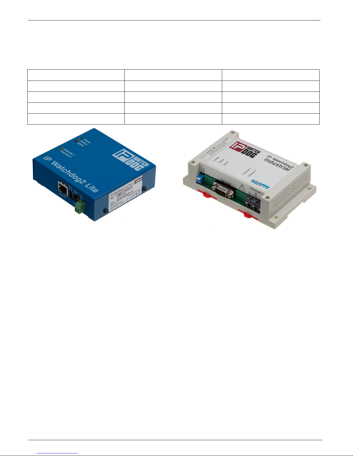
IP WatchDog2 Lite / Industrial
IP WatchDog2 Lite
IP WatchDog2 Industrial
Housing
Metal
Plastic
Relay outputs
max. 50V/1A
max 240V/16A
Serial line
NO
YES
External serial modem
NO
YES
IP WatchDog2 Lite
IP WatchDog2 Industrial
Page 4

IP WatchDog2 - Manual
HW group
March 2015
Page 4
Monitored functions and parameters
Incoming Ping
IP range – range of IP addresses defined by IP and mask, from which the
receiving PING can be accepted.
Timeout delay for reboot – time interval, in range from 0-1800 s ( 0
=disabled),that IP WatchDog2 waits for incoming PING before causing
RESET.
Outgoing Ping
Primary target IP – primary IP address where IP Watchdog2 sends the
PING and from which it awaits reply.
Secondary target IP – secondary IP address where IP WatchDog2 sends
the PING and from which it awaits reply, if primary target does not responds.
Quantity of failed ping for reboot – number of PINGs, that IP WatchDog2
assumes for lost before causing RESET.
Outgoing ping interval – interval between sent PINGs in range of 0-1800s
(0 =disabled).
Incoming HTML
page
(WWW client)
Server IP – IP address where IP WatchDog2 requires HTML page from.
Timeout delay for reboot – time interval, in range from 0-1800 s ( 0
=disabled), for this time IP WatchDog2 awaits for an request for a HTML
page, then RESET is performed.
Reading HTML page period – interval between demands for WWW pages
in range 0-1800 s ( 0 = disabled).
Outgoing HTML
page
(WWW server)
Request Page – address of HTML page offered to monitored device.
Provides number for further processing of canal and information about
acceptable IP address and IP address client, whose required page.
Device IP – IP address of WWW monitored client, from which the request
for releasing the HTML page is accepted.
Timeout delay for reboot - interval in range from 0-1800 s ( 0 = disabled ),
for this time IP WatchDog2 awaits for an request for a HTML page, then
RESET is performed.
Incoming RS232
String
(IP WatchDog2
Industrial only)
Incoming string – string in format ASCII, HEX or DEC awaits on port RS-
232 (* represents random sign).
Timeout delay for reboot – interval v rozsahu 0-1800 s ( 0 = disabled ), for
this time IP WatchDog2 awaits for an request for a HTML page, then
RESET is performed.
Page 5
IP WatchDog2 - Manual
HW group
March 2015
Page 5
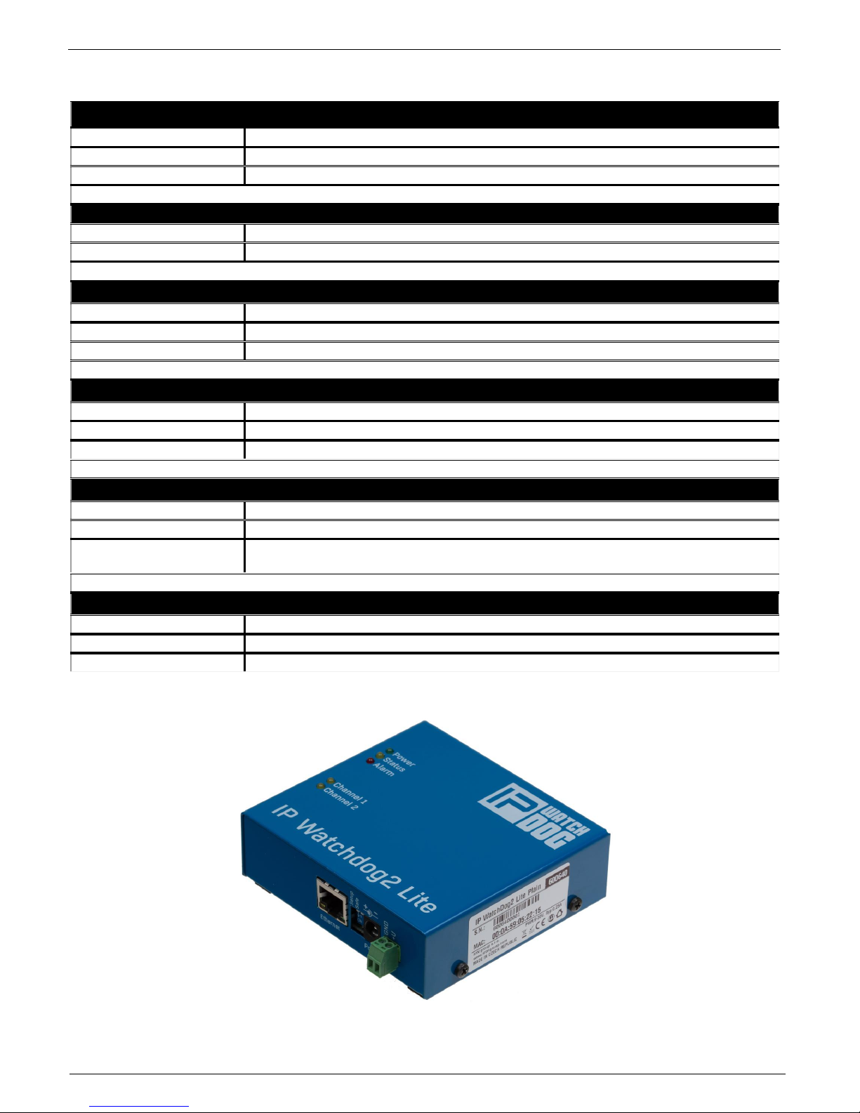
Technical parameters IP WatchDog2 Lite
Ethernet port
+ Interface
RJ45 (10BASE-T / 100BASE-Tx)
+ Compatibility
Ethernet: Version 2.0/IEEE 802.3
+ Supported protocols
IP: ARP, TCP/IP, NVT, RFC2217, UDP/IP, SNTP
Relay contact ampacity
DC voltage
max. 30V / 1A
AC voltage
max. 50V / 0,5A
Environment parameters
+ Operation temperature
-30°C to +85°C
+ Storage temperature
-5 to +75 °C
+ Relative humidity
5 to 95 % (non-condensing)
Mechanical construction
+ Mechanical construction
Metal, table construction With external wall bracket, DIN rail or Rack
+ Dimensions
100x94x31 / 260g
+ EMC
FCC Part 15, Class B, CE - EN 55022, EN 55024, EN 61000
POWER input
+ Port
POWER 9-30V DC
+ Type
Main device power input (typically 250 mA) + Power Out
+ Conector
Jack (barrel, inner 2.5 mm outer 6.3 mm),
Terminal Block
Power Output
+ Voltage
Power OUT = Power In
+ Current
Max. Power Adaptor minus 250mA or 1000mA
+ Connector
Terminal Block
Page 6

IP WatchDog2 - Manual
HW group
March 2015
Page 6
Technical parameters IP WatchDog2 Industrial
Ethernet port
+ Interface
RJ45 (10BASE-T / 100BASE-Tx)
+ Compatibility
Ethernet: Version 2.0/IEEE 802.3
+ Supported protocols
IP: ARP, TCP/IP, NVT, RFC2217, UDP/IP, SNTP
Serial port 1 - Channel 1
+ Data bites
8
+ Stop bity
1
+ Parity
None
+ RS-232 interface
RxD,TxD, GND
+ Speed of communication
adjustable in range 50..115200 Bd
Serial port 2 - Channel 2
+ Data bites
8
+ Stop bity
1
+ Parity
None
+ RS-232 interface
Not full serial port - RxD on pin 8 only!
+ Speed of communication
adjustable in range 50..115200 Bd
Relay contact load
DC voltage
max. 24V / 16A
AC
max. 240V / 16A
Environment parameters
+ Operation temperature
-5 to +50 °C
+ Storage temperature
-5 to +75 °C
+ Relative humidity
5 to 95 % (non-condensing)
Mechanical construction
+ Mechanical construction
Plastic, mountable on wall or DIN rail
+ Dimensions
145x90x40 / 225g
+ EMC
FCC Part 15, Class B, CE - EN 55022, EN 55024, EN 61000
POWER input
+ Port
POWER 9-30V DC
+ Type
Main device power input (typically 250 mA)
+ Connector
Jack (barrel, inner 2.5 mm outer 6.3 mm),
Terminal Block
Page 7
IP WatchDog2 - Manual
HW group
March 2015
Page 7
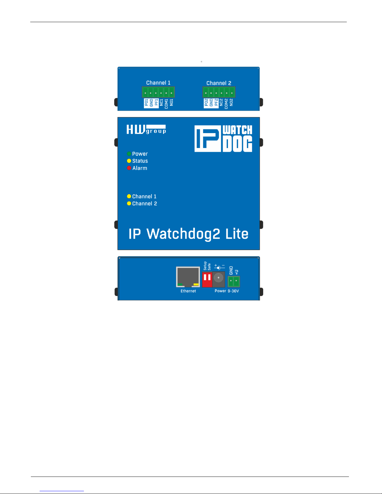
Connectors of the IP WatchDog2 Lite
Individual connectors and control elements as well as connection of the relays is shown on the
picture below:
LED
Power (Green) - lights, if connected and the device is working
Status (Yellow) - blinks when signal is accepted from the monitored device, blinking quickly
when being upgraded
Alarm (Red) - lights, if some of device is unavailable and IP WatchDog2 is performing reset
Channel1/Channel2 - lights when channel is switched (reset or manual switch)
DIP switches
Setup - is used to reset the device to the default configuration, if switched when the power
supply is
Safe - for manufacturer purposes only
Page 8
IP WatchDog2 - Manual
HW group
March 2015
Page 8
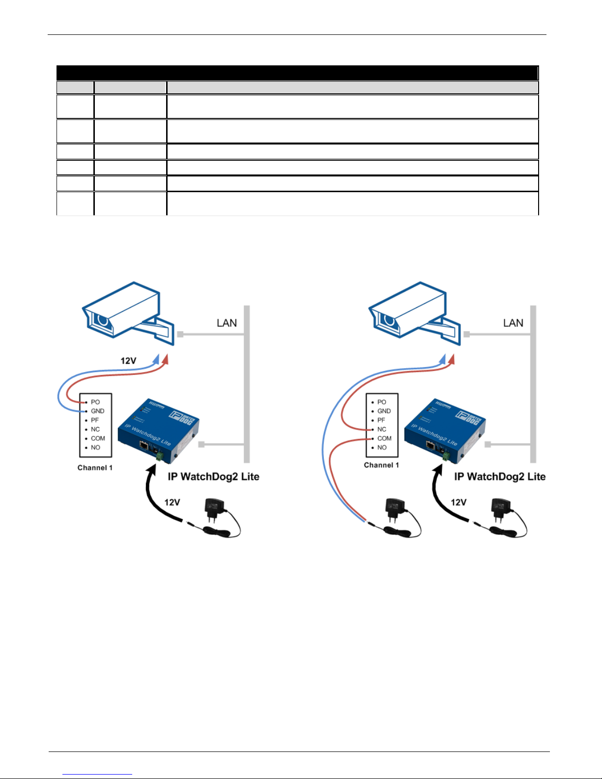
Outputs Channel1 / Channel2
Terminal board description
Pin
Power
Function description
PO
Power On
In the idle state this pin contains power supply of the IP Watchdog2 - axis of the power
connector.
PF
Power OFF
In Reset mode this pin contains power supply of the IP Watchdog2 - axis of the power
connector.
GND
Ground
Negative pole of the supply voltage. Is connected directly to GND.
NC
Normally Close
In Idle state this pin is connected with the appropriate COM pin
NO
Normally Open
In Reset state this pin is connected with the appropriate COM pin
COM
Common
Common pin - in case of switching contacts connected to relay housing
PF / PO Powered outputs usage
Page 9
IP WatchDog2 - Manual
HW group
March 2015
Page 9
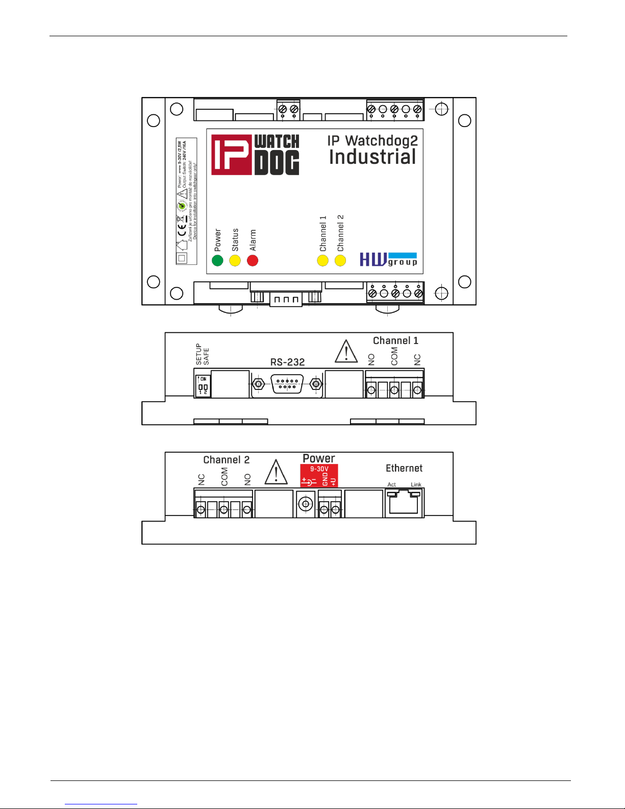
Connectors of the IP WatchDog2 Industrial
Individual connectors and control elements as well as connection of the relays is shown on the
picture below:
LED
Power (Green) - lights, if connected and the device is working
Status (Yellow) - blinks when signal is accepted from the monitored device, blinking quickly
when being upgraded
Alarm (Red) - lights, if some of device is unavailable and IP WatchDog2 is performing reset
Channel1/Channel2 - lights when channel is switched (reset or manual switch)
DIP switches
Setup - is used to reset the device to the default configuration, if switched when the power
supply is
Safe - for manufacturer purposes only
Page 10
IP WatchDog2 - Manual
HW group
March 2015
Page 10
Outputs Channel1 / Channel2
Description terminal board
Pin
Power
Function description
NC
Normally Close
In Idle state this pin is connected with the appropriate COM pin
NO
Normally Open
In Reset state this pin is connected with the appropriate COM pin
COM
Common
Common pin - in case of switching contacts connected to relay housing
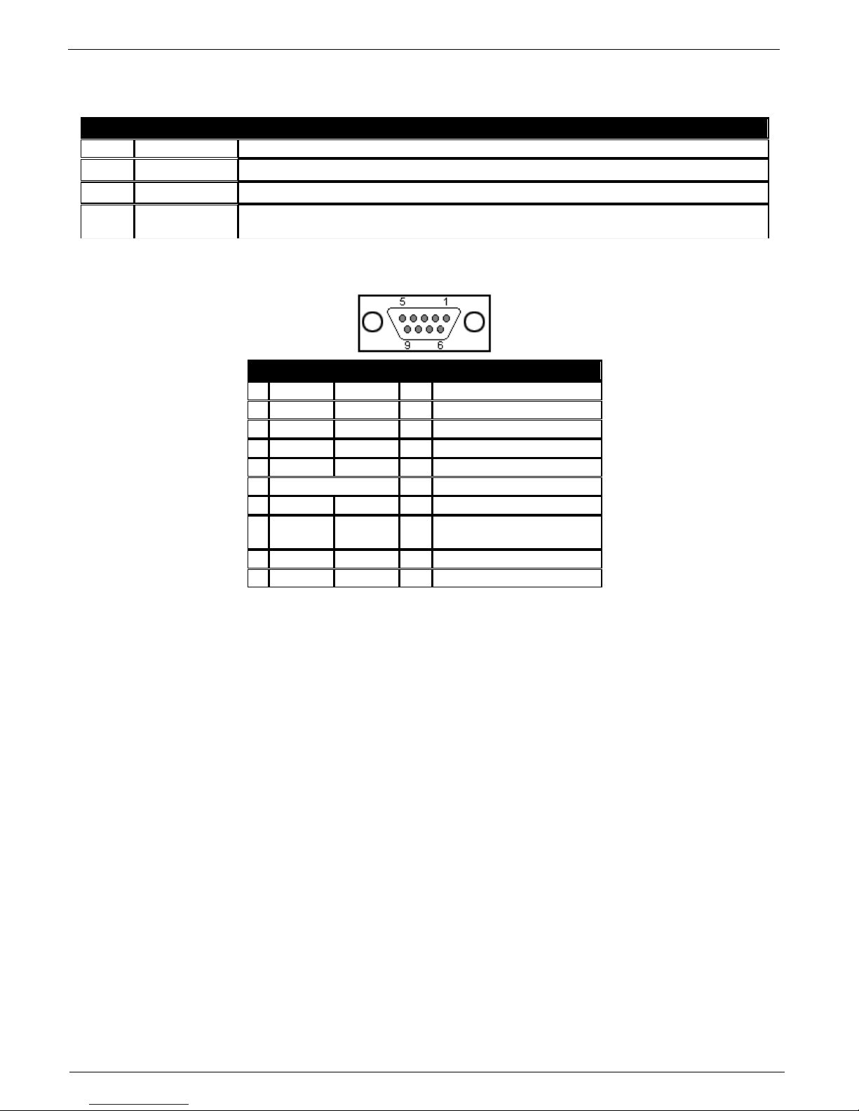
Serial - DB9M
Connector DB9M (RS-232)
Channel1
Channel2
1
DCD IN
Unused
2
RxD
IN
Receive Data
3
TxD
OUT
Transmit Data
4
DTR
OUT
Unused
5
GND
---
System Ground
6
DSR
IN
Unused
7*
RTS
OUT
Clear to Send, (Receive
Data) 8
RxD
IN
Request to Send
9
RI IN
Unused
Page 11

IP WatchDog2 - Manual
HW group
March 2015
Page 11
First steps
In this chapter you will learn how to connect the IP WatchDog2 easily to your PC or company
network, setting it up and putting it into service.
Device connection
The following procedure is recommended for quick setup of the device. Detailed description of all
parameters and commands can be found in chapter called "Parameters description".
Cable connection
Set switches from DIP1 and DIP2 into OFF position.
Connect IP WatchDog2 to the Ethernet 10/100 Mbit network.
Connect the supplied power adaptor to power grid and plug the connector of the power adaptor
into power connector of the IP relay. The Power LED indicator should light up.
If the Ethernet connection is OK, the LINK indicator should light up.
Page 12
IP WatchDog2 - Manual
HW group
March 2015
Page 12
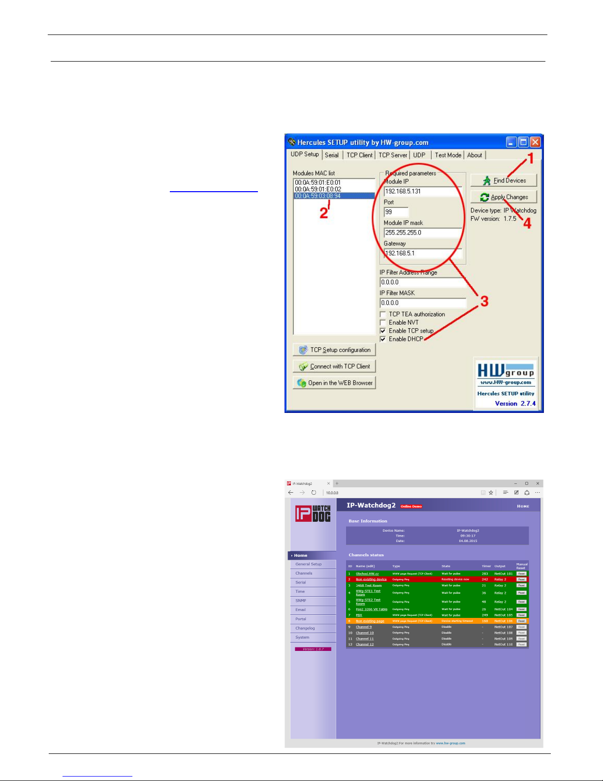
Primary configuration of Ethernet parameters
The primary configuration of the IP WatchDog2 (IP address, network mask and gateway) can be
done via UDP Setup - IP WatchDog2 must be found on local part of ethernet network.
UDP Setup - Searching the device using UDP setup
Launch the program „HerculesSetup.exe,“
which can be found in root directory on
supplied CD. The latest version of the
program can be also downloaded for free
from our web pages www.HWgroup.cz .
In the UDP Setup“, tab, press the „Find
modules“, (step 1 see picture). The
device's MAC address should appear in
the left column.
Click on MAC adress (step 2). In the field
„Required parameters“, the configured
device parameters should appear.
Note: If you wish to change these basic
parameters (it is necessary to set at least IP
address, port, mas and gateway), enter
desire parameters into proper fields (3) and
press the „Set module“ (step 4) When
entering IP address and Gateway manually, it
is also necessary to disable assigning
DHCP by the server (clear Enable DHCP field)
Enter the IP address of the device into your
WWW browser The Main Page of www
interface will appear.
Detailed information on configuration
methods over www interface can be found in
the chapter called Device configuration via
WWW.
Page 13
IP WatchDog2 - Manual
HW group
March 2015
Page 13
Device configuration via WWW
IP WatchDog2 contains a WWW interface allowing easy and detailed attendance of the device
activity. The interface consists of four HTML pages which can be called by entering IP address of
the device from your web browser.
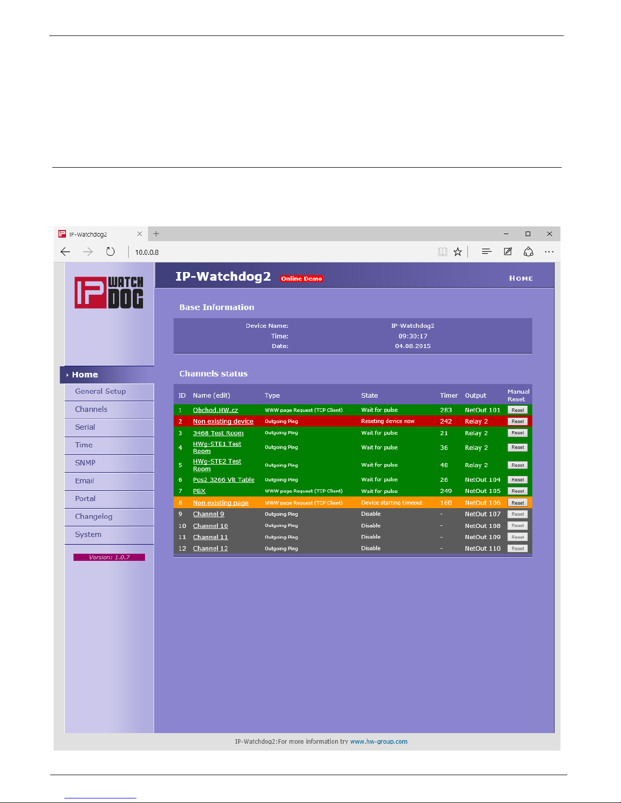
IP WatchDog2 Main Page
After entering WatchDog2 IP address to the web browser you will get a main page showing the
basic parameters of WatchDog2 channels and statistics for the last 20 operations of each channel.
In the upper part of the screen you can see links for advanced properties configuration of the IP
WatchDog2:
Page 14

IP WatchDog2 - Manual
HW group
March 2015
Page 14
Section Basic Information
Device name – User name of the device. Can be modified in the tab General Setup
Time – Machine time of the device – configuration can be changed in the tab Time. The valid
time is usually taken from the Internet
Date - Machine date of the device – configuration can be changed in the tab Time. The date is
usually taken from the Internet
Section Channel Status
Name – name of the monitored device (see Channels).
Type – actual assigned function to the channel (see Channels):
o Incoming Ping - IP WatchDog2 waits for ICMP command - PING Request from the
defined address or range of addresses defined by IP and mask.
o Outgoing Ping - IP WatchDog2 sends the ICMP command PING Request to the
defined primary IP addresses and awaits response. If not received, the same
command is sent to the secondary IP.
o Outgoing HTML page - IP WatchDog2 waits for download HTML page from WWW
server which is situated on defined IP address.
o Incoming HTML page - IP WatchDog2 waits requesting own WWW page from
monitored device defined with IP address.
o Incoming RS232 String - IP WatchDog2 monitor dates on appropriate port RS-232
and awaits requested string.
State – information about actual state of channel:
o Disable (grey) – channel is deactivated. Allows manual operation of the relay through
Channels
o Wait for Living pulse (orange) - channel waits for arrival of the booting (first) pulse.
o Wait for pulse (green) – channel waits for arrival refreshing pulse.
o Device Idle (orange) – channel was reset. Awaiting first refreshing pulse.
o Reseting device now (red) - channel being reseted.
o Device starting timeout (orange) – waiting for the end of mandatory period after reset
channel
o Manual Reset (red) – channel was annulled manually
o Config change (green) – the process of changing the channel configuration
Timer – Depends on the state of the channel – viz upper part – and determines how long the
state will end.
Output – Depended Output
Reset – button for manual Reset.
Page 15

IP WatchDog2 - Manual
HW group
March 2015
Page 15
General Setup
Section Base
Device Name – the name of the device (IP-WatchDog2) - allows to distinguish individual IP WatchDog2 in
network.
The device name can have a maximum of 16 characters.
WWW Info Text – text of the footer WWW pages – suitable for contact information for example the data centre
manager.
Section Network
DHCP – enable setting of an IP address with DHCP server, if available – switch on or off DHCP, depends on user
and administrator needs.
IP Address – IP address of IP WatchDog2 – assigned by the administrator of the network.
Network Mask – mask of network – assigned by the administrator of the network.
Gateway - IP address of default gateway - assigned by the administrator of the network.
DNS Primary / DNS Secondary – IP address of DNS server – assigned by the administrator of the network.
HTTP Port - number of port, where the built in WWW server is listening - change the number to have more IP
WatchDog2 devices accessible from an external network via the router. Ask your network administrator about
any changes. The default port is 80.
Security section: Device Admin
Username / Password - username and password for security access to IP WatchDog2.
Page 16

IP WatchDog2 - Manual
HW group
March 2015
Page 16
Channels
HTML pages Channels provides complete management of the monitoring channels.
Section Basic Setup
Channel enabled/disabled - switch the channel on / off
Channel name – name of the device. Makes configuring channels and solving the issues with
monitored devices easier. Name can contain up to 20 symbols.
Page 17

IP WatchDog2 - Manual
HW group
March 2015
Page 17
Section Incoming Ping (displayed depending on the Channel Type)
Timeout for reboot – time interval that IP WatchDog2 waits for incoming PING before
causing RESET.
IP range - range of IP addresses defined by IP and mask, from which the receiving PING can
be accepted.
Page 18

IP WatchDog2 - Manual
HW group
March 2015
Page 18
Reset by Ping – Outgoing Ping (displayed depending on the Channel Type)
Timeout for reboot – interval for sending requested PINGs.
Ping primary address – primary address of the target device. The IP address and domain
name can be specified.
Ping secondary address – secondary address of the target device. The IP address and
domain name can be specified. If only one device is monitored (or one address, the
secondary address is left blank.
Ping Number – number of sent PINGs in interval Timeout for reboot. At least one must have
an answer or state Reset will follow.
Monitoring by HTML page – HTML page (TCP Server)
Timeout for reboot – time interval that IP WatchDog2 waits for incoming PING before
causing RESET.
Request Page – WWW page http address that must be requested from the IP WatchDog2
by the remote device, or Reset will follow.
Page 19

IP WatchDog2 - Manual
HW group
March 2015
Page 19
Monitoring by HTML page – WWW page Request (TCP Client)
Timeout for reboot – time interval that IP WatchDog2 waits for incoming PING before
causing RESET. This parameter should be chosen with regards to the speed of the
transmission line and server load.
Server address - address of the target page (URL), which will be requested.
Request Number – number of requests sent during the interval Timeout for reboot. At least
one answer must come otherwise the Reset state will follow.
Monitoring by RS-232 String
Timeout for reboot – time interval that IP WatchDog2 waits for incoming PING before
causing RESET.
Requested string - sets the monitored. HEX, DEC or ASCII format is available. Combining
HEX, DEC and ASCII characters can be achieved using prefixes:
o $ - For HEX characters (example : $4F$4B$0D$0A or $4f$4b$0d$0a);
o # - Escaped DEC characters – 3numbers (#079#075#013#010);
o <string> - for ASCII characters.
Note: Characters can also be represented byt ? for any single character and * for any number of
characters - for example if IP-WTD is set, *IP_WTD $10$13 is accepted.
Page 20

IP WatchDog2 - Manual
HW group
March 2015
Page 20
Section Output action Setup
Reboot Hold Time – Reset length. Allows you to set the time when the channel (relay), is in
reset status (manual and automatic) Interval can be in the range of 0-1800 seconds.
If Reboot Hold Time = 0, then the Reset state lasts until the next refreshing impulse. This
mode is designed to activate the backup device or identify the error state using other
signalization means. Find more in the Reboot Hold Time - Application tips chapter.
Timeout After Reboot – time interval that IP WatchDog2 waits before causing other Reset
after the previous one (or after first launch of the device), if monitored data are not received.
The interval can be from in range of 0-1800 seconds. The "0" value causes device to wait for
first incoming data from the monitored device.
First living pulse – waiting for the arrival of the first data from the monitored device, and then
the Time for reboot countdown starts (see below).
Output Select – selects the output (relay) which will reset the monitored device. There is a list
of available physical (Relay1 or Relay2) and virtual outputs (NetOut1xx). Virtual outputs are
set to Output Setup section.
Send e-mail when reboot (in future) – send e-mail in case of the device reset.
Send SMS when reboot (in future) - send SMS in case of the device reset.
Beeper Enable (in future) – activate sound signalization in case of reset the device reset. If
checked, you will hear 3x short beeps at the time of switching the output.
During Beeper on Reset (in future) - The sound signalization during the device reset
Section Output Setup (Virtual outputs only)
Name – name of Outputs
Target Outputs – type of remote Device
Remote IP Address – address of the remote device
Remote IP Port – HTTP port remote device`s
Remote ID – ID of remote Outputs .
Username – if the remote device is protected by a username and password
Password – if the remote device is protected by a username and password
Page 21

IP WatchDog2 - Manual
HW group
March 2015
Page 21
Serial
Settings of communication parameters of serial ports (channels)
Basic Parameter
Serial - Enable or disable port
Port name - name of the port. Makes configuring channels and solving the issues with
monitored devices easier. Name can contain up to 20 symbols.
Requested string - Searched string in the data flow. Finding the required string it is deemed to
constitute proper operation of the monitored equipment
Serial Parameters
Baud Rate - Current baudrate
Data - Number of data bits
Parity - Parity None/Odd/Even
Stop - Number of stop bits 1 or 2
Page 22
IP WatchDog2 - Manual
HW group
March 2015
Page 22
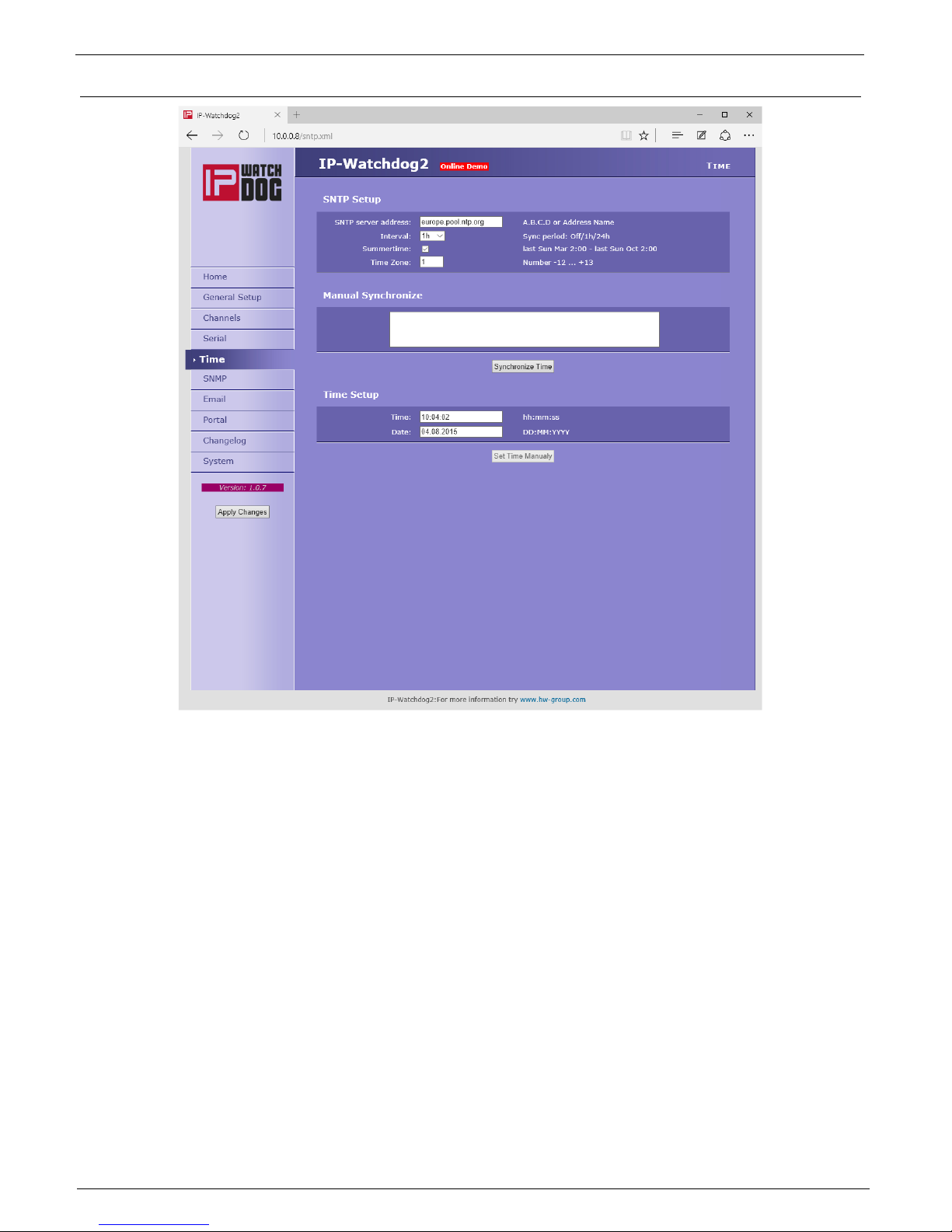
Time
Section SNTP Setup
SNTP Server – IP address or domain address of server for time synchronization
Interval – interval of time synchronization with the server.
Summertime - enable automatic switching between summer and winter time (DST) - used to
set the correct system time.
Time Zone – setting the time zone location IP WatchDog2 - used to set the correct system
time.
Manual synchronize
Debug Window
Synchronize Time is used to perform an immediate synchronization with the time server. Can
also be used to test the settings.
Section Time Setup
Session Time Setup allows you to fill the current date and time manually when you can not use
synchronization with the time server. After the loss of power this information may be lost.
Page 23

IP WatchDog2 - Manual
HW group
March 2015
Page 23
SNMP
General SNMP Settings
System Name – The device name coincides with the name of the device
Systém Location – system location, such as "IT room, floor 2".
System Contact – Contact the system administrator, for example, e-mail address
SNMP port – Port settings for communication within the SNMP [161].
SNMP Access
Defines the permissions and name groups of users can work with the Poseidon.
Community – Text the name of the group that are assigned rights (default Public and Private)
Read – add permission to the community to read variables over SNMP
Write – add permission to the community writing values to variables over SNMP
Enable – enable or disable the group
SNMP Trap Destination
Defines the destination for sending SNMP traps.
Community – Text the name of the group SNMP Trap
IP address –Destination address which will be sent SNMP traps.
Port – The destination port to which traps will be sent.
Enable – Enables transmission of SNMP traps to this destination.
Page 24
IP WatchDog2 - Manual
HW group
March 2015
Page 24
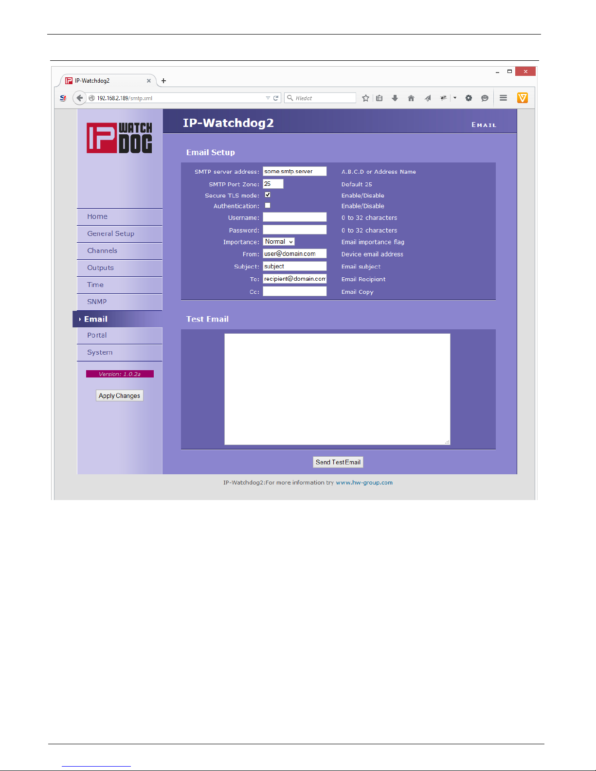
E-mail
Email Setup Section
SMTP Server – IP address or domain address of the SMTP server.
SMTP Port – port number on which listens e-mail server - default 25.
Secure TLS mode - check if SMTP server requires a secure communications using SSL / TLS.
Authentication - enabled authentication- check if the SMTP server requires authentication.
Username – user name for authentication to SMTP server. Unless Authentication check box is
selected, the content of this field is irrelevant.
Password – authorization password for the SMTP server. Unless Authentication check box is
selected, the content of this field is irrelevant.
Importance – sets the priority e-mail messages. Important for filtering and further processing
alarm messages.
Page 25

IP WatchDog2 - Manual
HW group
March 2015
Page 25
FROM – from - e-mail address of the sender, ie
units IP WatchDog2. Address may be required
from SMTP servers and can be used to
identify the units IP WatchDog2, possibly for
filtering and processing of alarm messages.
Subject - the subject of e-mail - the contents of
the field can be used to identify the units IP
WatchDog2, possibly for filtering and
processing of alarm messages.
TO – To - The e-mail address to be sent alarm
e-mail.
CC – copy - e-mail address to be sent a copy of
alarm e-mail.
1) Correct IP address for IP Gateway
2) DNS server in the network settings
3) SMTP server and its port
4) Turning on authentication and
correct name and password
5) Off Spam filter in mail box
Check for sending Email
Page 26
IP WatchDog2 - Manual
HW group
March 2015
Page 26
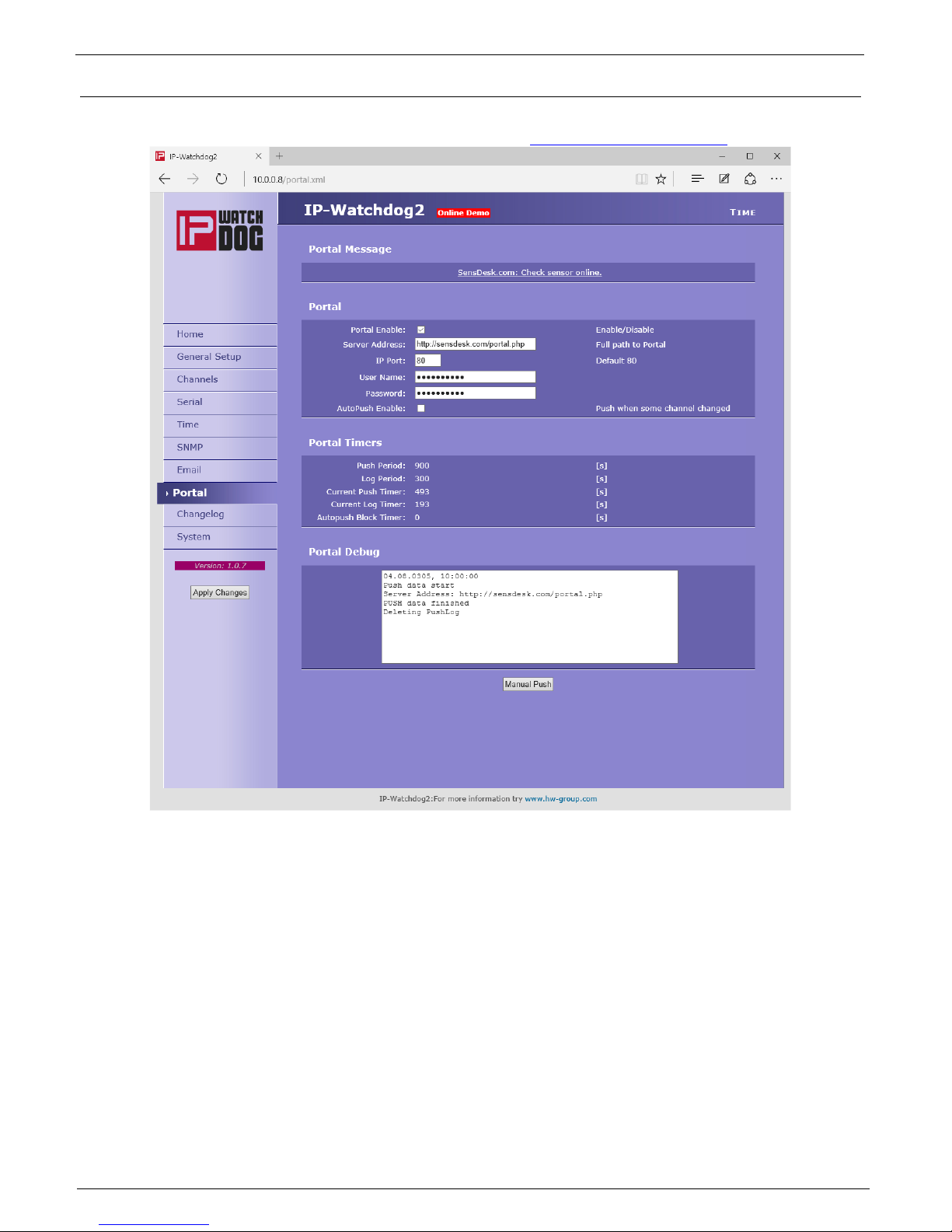
Portal
This page is used to set parameters for sending data to a remote HWg-PUSH portal. For more
information about protocol or portal solutions, please visit http://www.hw-group.com
Portal Message Section
The message from the portal, contains links to graphs etc. It depends on the type of website.
Section Portal
Portal – Enable or disable this feature
Push Period – Period of sending data to a remote server. The period is adjusted
retrospectively from the portal
Server address – the full URL of the remote server
IP Port – Port on which the portal listens
Username – User name for assigning IP WatchDog2 to user. Receive from the portal
administrator.
Page 27

IP WatchDog2 - Manual
HW group
March 2015
Page 27
Password – Password for assigning IP WatchDog2 to user. Receive from the portal
administrator
Portal Timers
For debugging purposes only
Push Period - The period for sending data to a remote portal. A period determined by the
portal and can not be changed by the user.
Log Period - The period of storage of data for portal into a cache. A period determined by the
portal and can not be changed by the user.
Current Push Timer - The timer indicates for how long the data will be sent to a portal
Current Log Timer – The timer indicates for how long the data will be stored for portal into a
cache.
Autopush Block Timer - Event counter for Autopush. In the case of exceeding the allowed
number of events per cycle of Push, the AutoPush feature will be blocked.
Portal Debug
Debug window of sending data to the portal
Manual Push - button for immediate shipment of the data to a portal
Page 28
IP WatchDog2 - Manual
HW group
March 2015
Page 28
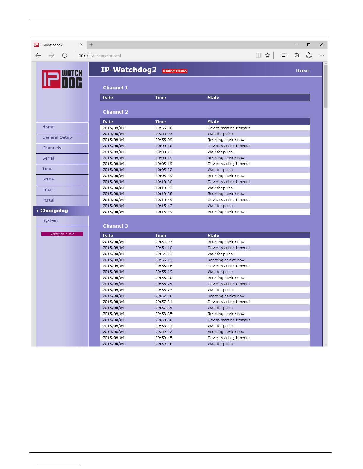
Changelog
Page 29
IP WatchDog2 - Manual
HW group
March 2015
Page 29
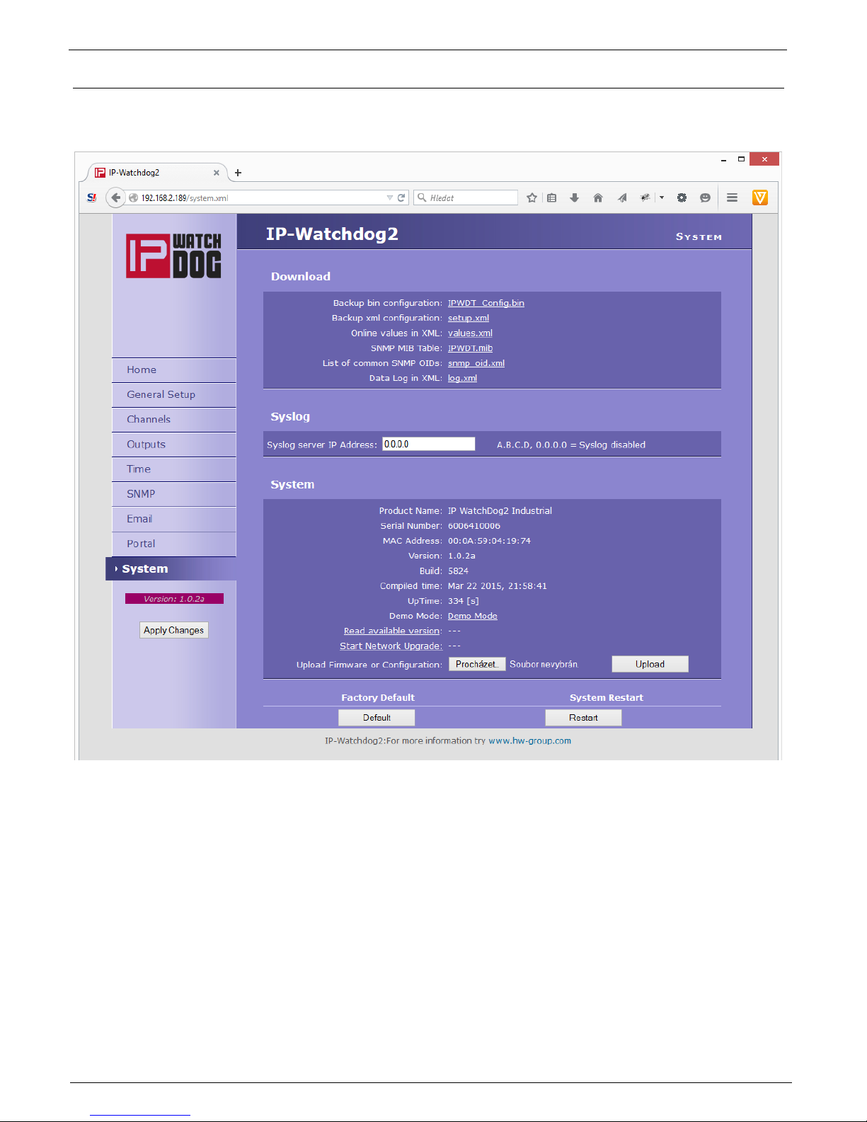
System
System tab grant users access to the most important system information such as operating time or
firmware version, and operations such as restart IP WatchDog2 or upgrade firmware.
Download
Backup bin configuration – backup of configuration in format BIN - click on the link to save the
current configuration of IP WatchDog2 after its final setting in case it needs restoration.
Backup XML configuration – backup configuration in XML format - click on the link to save the
current configuration of IP WatchDog2 after its final setting in case it needs restoration.
SNMP MIB Table – SNMP MIB file - address of MIB file containing the definition of SNMP
variables.
List of common SNMP OIDs – an overview of the most important OID MIB table.
Data Log in XML – List of recent events in XML
Page 30

IP WatchDog2 - Manual
HW group
March 2015
Page 30
Syslog
Syslog server IP Address – Address of Syslog server
System Section
Version – firmware version. Used for diagnostic purposes in case of problem solving.
Compile time – Time compilation firmware. Used for diagnostic purposes in case of problem
solving.
Build – compilation. Used for diagnostic purposes in case of problem solving.
UpTime – running time of the device since the last start or reboot. Used for diagnostic
purposes in case of problem solving.
Demo mode - activated demo mode prevents any change in the configuration of your
equipment.
In this mode, visitors can freely browse and view all pages of the web interface, but changing
values, they are not allowed. Thus setting the device can be placed on the public internet
without the risk of changes in its configuration.
Upload Firmware or Configuration – allows download into the device a newer firmware or
configuration file. Restoring configuration may fail if it is too much difference in firmware
versions.
Factory Default Section
Restores the factory settings. Default IP address is 192.168.10.20 and the user name and password
are not defined.
System Restart Section
Reboot the device.
Page 31

IP WatchDog2 - Manual
HW group
March 2015
Page 31
Application tips
Reboot Hold Time
Besides the classic reset of the monitored device and its following release IP WatchDog2 still a
possibility of permanent Reset state in case the monitored device does not respond to the demands
of IP WatchDog2 or does not send periodically refresh impulses. This mode is activated by setting
the parameter Reboot Hold Time to 0. If in this case state is performed RESET, the channel (or its
output) in this state until the monitored device reports itself again, or if no channel is deactivated.
The function is designed for cases where IP WatchDog2 does not reset directly monitored device or
when one of the channels used to activate the backup device or other alarm system.
Note: If the value Reboot Hold Time = 0, the IP WatchDog2 in a special mode Reset function and
especially Manual Reset behave somewhat differently than described on the previous pages,
because the Reset state can not be ended by itself. This is especially true when using Manual
Reset button with deactivated channel when there is no standard way how to reverse Reset state
and the only way is to activate the channel and initialize the refresh impulse.
Page 32

IP WatchDog2 - Manual
HW group
March 2015
Page 32
Testing and operation hints for Windows and Linux
Test functions Incoming Ping
Test command functions Incoming Ping for Windows
Application of the ICMP PING function in
Windows is very simple, but can be little
tricky. Ping testing can be managed via the
Start menu, select Run, Windows command
line cmd and press OK. Application opens a
command prompt (in older versions of MS
Windows MS-DOS window). Write inside
Ping ip_address_of_watchdog, for
example ping 192.168.5.60
The result will be roughly the following statement:
If you want to send the PING
permanently, enter the command with the
-t:
Ping 192.168.5.60 –t
Command line can also be launched using the standard windows shortcuts, which can be found at the
following positions:
Windows 98: Start | Programs | MS-DOS Prompt
Windows NT: Start | Programs | Command Prompt
Windows ME: Start | Programs | Accessories | MS-DOS Prompt
Windows and above: Start | Programs | Accessories | Command Prompt
Windows 8: Start | CMD
There can be some issues with command PING in Windows in case you are using firewall, or you have
got Windows XP with service pack SP2, which contains simple firewall itself. If the PING does not work,
on IP WatchDog or from it, please check that the firewall configuration does not block ICMP commands
echo reply and echorequest (if it does, unblock them) or use other method (like WWW page). Some
servers themselves block the PING commands to prevent overloading and “pinging to death” (so called
Ping of Death attack).
Microsoft Windows XP [Version 5.1.2600]
(C) Copyright 1985-2001 Microsoft Corp.
C:\Documents and Settings\Vít Olmr>ping 192.168.5.60
Command PING on 192.168.5.60 with length 32 bytes:
Answer from 192.168.5.60: bytes=32 time=1ms TTL=64
Answer from 192.168.5.60: bytes=32 time < 1ms TTL=64
Answer from 192.168.5.60: bytes=32 time=1ms TTL=64
Answer from 192.168.5.60: bytes=32 time < 1ms TTL=64
Statistics for ping 192.168.5.60:
Packets: Sent = 4, Received = 4, Lost = 0 (0% loss),
Approximate time of the adoption of the response in
milliseconds:
Page 33

IP WatchDog2 - Manual
HW group
March 2015
Page 33
Test command for Incoming Ping under Linux/Unix
Using PING command under Unix and Linux OS is as simple as in the case of Windows, maybe even
easier because you don’t have to run the command line.Just enter the following into the console:
Ping 192.168.5.60
Operational command of the function Incoming Ping under Windows
Windows provide a free service for Windows Server 2000/2003 and Windows 2000/XP, that can be
downloaded from
http://www.hw-group.com/download/IPWDT_Setup_1.0.zip
allowing sending ping to the defined address in regular intervals.
The form of services is applied to allow running it automatically
even on server systems without a need of logging in. After
Unpacking and installation it is necessary to modify a
configuration file IPWDT.ini, that can be located at C:\Program
Files\HW group\IPWD Tools.
It contains following:
Interval is measured in seconds, Debug parameter defines whether the communication will be logged in
the directory C:\Program Files\HW group\IPWD Tools (max. file size is 5MB).
An icon for IP WatchDog Tools Control created in Control panel allows
activation and deactivation of the services
Operational command for Incoming Ping under Linux/Unix
In Unix systems it is used so called demon cron, that executes commands according to the crontab,
that is a simple text document that contains data in a tab in following format:
Where:
1. minute
2. hour
3. day of a month
4. month
5. day of a week (0 - Sunday, 1 - Monday... 6 - Saturday)
6. user's account
7. path to the program or command that should be executed
This tab can be edited easily using a command crontab –e, that opens the specific document. The
created entry can look like this:
This command will execute the ping every minute.
*/1 * * * * root ping 192.168.5.60
1 2 3 4 5 6 7
*/1 * * * * user's_account command
[PING]
IP=192.168.1.9
INTERVAL=10
DEBUG=2
Page 34

IP WatchDog2 - Manual
HW group
March 2015
Page 34
Test of Outgoing HTML Page function
Testing of Outgoing HTML Page function
For initial testing of this feature is available in the on-line form, which can be found on this address
http://www.hwg.cz/products/ip_watchdog/test/test_outgoing_page.html
just type an IP address of the IP WatchDog, port, resp. IP WatchDog2 always port 80, but in the absence
of public IP address can be used address translation (NAT – network address translation). Then enter
your public IP and port number configured in the NAT.
Test command for Outgoing HTML Page under Linux/Unix
Unlike Windows, the Unix systems again popular cron, while the command position we will use
function wget - wget http://192.168.0.1/index.html
for example:
This command will start the ping every minute.
*/1 * * * * root wget http://192.168.0.1/index.html
Page 35

IP WatchDog2 - Manual
HW group
March 2015
Page 35
Mechanical dimensions of IP WatchDog2 Lite
The device is in metal box with option to mount on wall or DIN rail.
Page 36
IP WatchDog2 - Manual
HW group
March 2015
Page 36
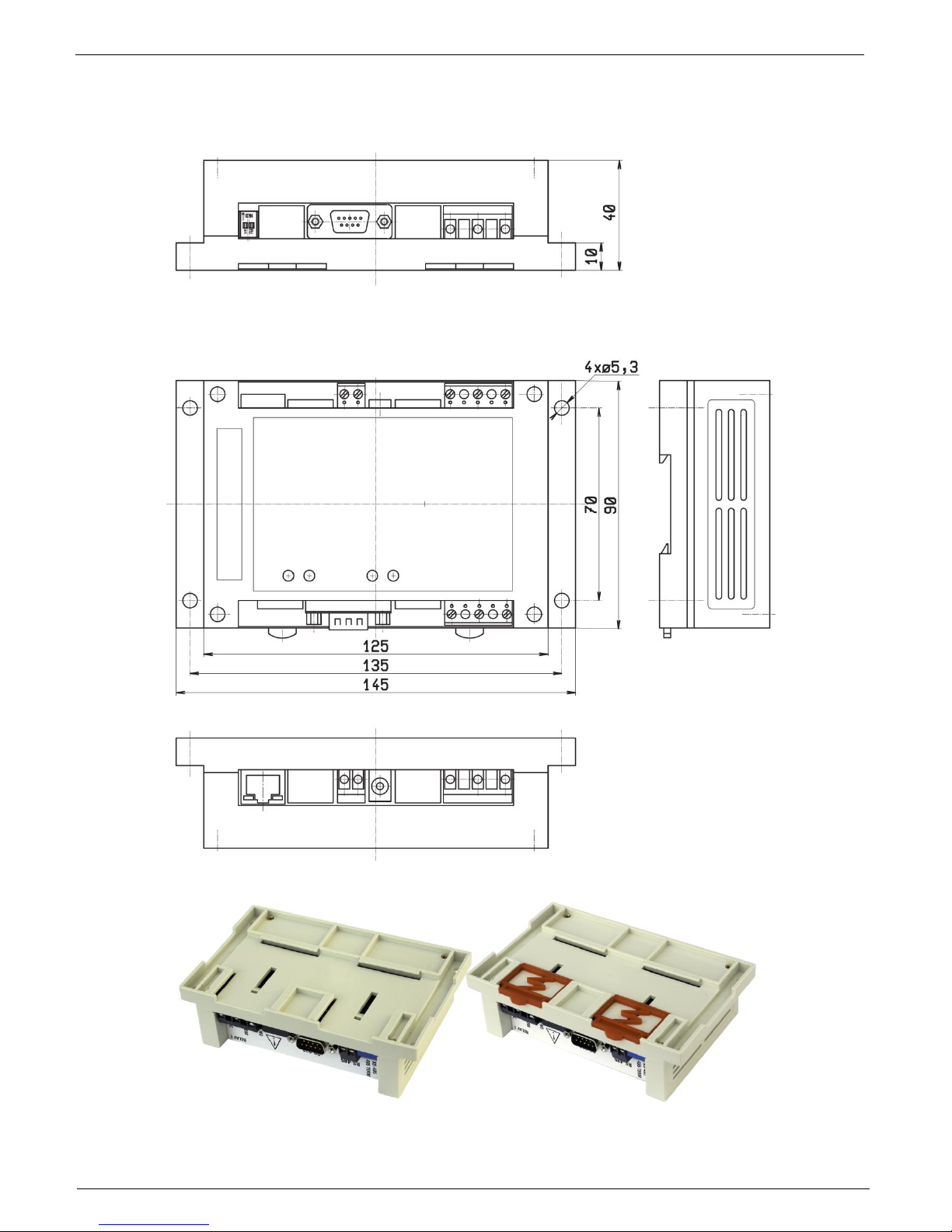
Mechanical dimensions IP WatchDog2 Industrial
The device is in solid box with option to mount on wall or DIN rail.
 Loading...