

Page 1
IP Relay
2x Relay controlled over Ethernet
+ RS-232 / Ethernet converter (Terminal server)
EN 900 478a
Page 2

IP Relay – 2x relay + RS-232 / Ethernet converter
HW group
June 2006 www.HW-group.com
Page 2 / 28
Shipment contents
Complete shipment of the IP Relay contains following items:
• IP Relay in a metal box and mechanic version corresponding to the ordering number
• A 1:1 serial prolonging cable (DB9F - DB9M) for the device setup via RS-232
• Power adaptor in European version
• Printed manual + datasheet
• CD with the necessary software
o IPRC (IP Relay Controller)
o HW VSP (HW Virtual Serial Port)
o Hercules utility
Page 3

IP Relay – 2x relay + RS-232 / Ethernet converter
HW group
June 2006 www.HW-group.com
Page 3 / 28
Table of contents
Shipment contents...........................................................................................................................2
Table of contents..............................................................................................................................3
Characteristics and basic properties .............................................................................................4
Features .........................................................................................................................................4
Connection topology ....................................................................................................................... 5
Connector descriptions...................................................................................................................7
Using the device...............................................................................................................................8
Quick setup..................................................................................................................................... 8
Controlling the IP Relay with the IP Relay Control 1.2 software .....................................................9
Controlling the IP Relay with HW Virtual Serial Port..................................................................... 10
SETUP troubleshooting ................................................................................................................ 10
Controlling the Relay and LED diodes .......................................................................................... 11
Setting other parameters of the device ......................................................................................... 13
HW VSP - Virtual Serial Port..........................................................................................................15
IPRC – IP Relay Control.................................................................................................................17
Basic characteristics of IPRC .......................................................................................................17
Description of configuration parameters.....................................................................................19
Default device configuration .........................................................................................................19
Device network parameters .......................................................................................................... 20
Parameters of TCP and UDP connection .....................................................................................21
Serial port parameters .................................................................................................................. 22
Other device parameters .............................................................................................................. 23
Application hints............................................................................................................................25
Free application software.............................................................................................................. 26
Basic types of communication .....................................................Chyba! Záložka není definována.
Mechanical dimensions.................................................................................................................27
Device versions..............................................................................................................................28
Contact............................................................................................................................................28
Page 4

IP Relay – 2x relay + RS-232 / Ethernet converter
HW group
June 2006 www.HW-group.com
Page 4 / 28
Characteristics and basic properties
IP Relay combines two relays controlled over Ethernet and RS232 / Ethernet converter. The device can reset a remote device
via Ethernet or switch its power supply on or off. IP relay can be
also used as a remote serial port.
Features
• Ethernet - RJ45 (10BASE-T - IEEE 802.3)
• RS-232 Serial port (RxD, TxD, CTS, RTS, GND)
o 7, 8, or 9 data bits;
o baudrate: 50..115200Bd;
o HW/SW handshaking
• Testing software and virtual serial port for Windows 2000/XP available on a CD
• The examples of remote control by Java, VisualBasic, Delphi and PHP commands
available
• Two independent relays controlled via Ethernet by NVT commands (M2M protocol).
Standard relay configuration:
o Relay 1: Controls breaking contact
leading out the power supply,
output clips can be connected
directly as a power supply for an IP
camera, microwave modem or a
power relay.
o Relay 2: Switching contact can be
connected to any RESET button
Other possible contact configurations
can be found in the table at the end of this manual.
• DIP2 switch intended for free use e.g. for identification of service works.
• Possible ways of device configuration
o RS-232 Setup (over serial port using any RS-232 terminal - 9600 8N1)
o UDP Setup (configuration of basic network parameters)
o TCP Setup (remote configuration in the terminal via TCP)
• Access security and relay control:
o You can limit access to the device only from a predefined IP address range
o TCP connection can be secured using a 128-bit TEA algorithm
• Metal box dimensions: 25 x 82 x 90 [mm]
The device can be fitted on a DIN molding. We can supply side brackets for wall-mounting
upon request.
Page 5
IP Relay – 2x relay + RS-232 / Ethernet converter
HW group
June 2006 www.HW-group.com
Page 5 / 28
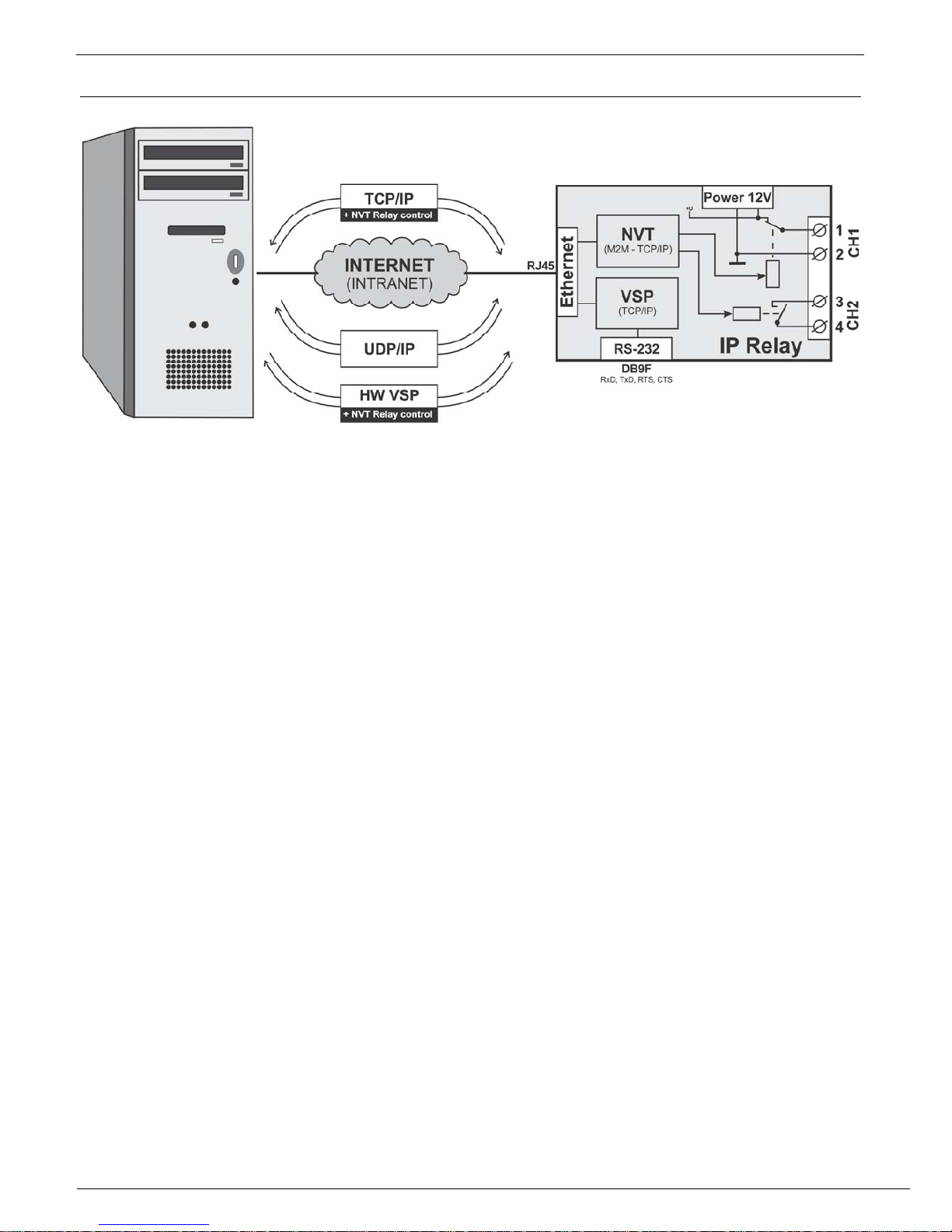
Connection topology
• TCP/IP - NVT
After powering up, the device listens on the given port and awaits TCP client connection.
When the client connects, data from the Ethernet are sent to the serial line and vice versa.
If the client is not connected and data are coming from the serial line, they are stored in a
buffer (cca 16 kB) and transmitted immediately after establishing a connection.
Both relays can be controlled by NVT type M2M protocol. The protocol extends the
implemented RFC 2217 (controlling the serial port via Ethernet). The device does not
have a WWW interface. To control the device you can also use a IPRC program,
Hercules Utility or programmer examples for JAVA, Delphi, Borland C++, Visual Basic,
PHP and others.
TCP/IP Client/Server mode - IP Relay keeps the TCP server function but when any data
are received from the serial line, it is stored into the buffer, the IP relay switches into a
TCP Client mode and tries to establish a TCP connection on the predefined IP address of
the opposite side.
• HW VSP
With the help of HW VSP (version 1.9 and higher) you can create a virtual serial port (e.g.
COM 5), which will be redirected to a relay’s RS-232 port. Both output relays are then
controlled from the “IP Relay” tab of the HW VSP program.
• UDP
UDP connection allows the data transfer to the RS-232 only, not controlling the device
Page 6

IP Relay – 2x relay + RS-232 / Ethernet converter
HW group
June 2006 www.HW-group.com
Page 6 / 28
Technical parameters
Ethernet port
+ Interface
RJ45 (10BASE-T / 100BASE-Tx)
+ Compatibility
Ethernet: Version 2.0/IEEE 802.3
+ Supported protocols
IP: ARP, TCP/IP, NVT, RFC2217, UDP/IP
+ Network modes
TCP/IP server, TCP/IP client/server, UDP/IP
+ Communication security
128-bit TEA cipher, predefined range of IP addresses
Serial port 1 DB9F
+ Data bits
7, 8 or 9
+ Stop bits
1 or 2
+ Parity
None / Odd / Even / Mark / Space
+ RS-232 interface
RxD,TxD,RTS,CTS,GND
+ Communication speed
Adjustable in the range of 50..115200 Bd
Channel configuration possibilities
PO (Power On) When device switched on, the external supply voltage is lead out over (A = +,
B = GND) Max current 100mA (50mA/Channel).
PF (Power Off) When device switched on, the pins A and B are unpowered (A = +, B = GND)
Max current 100mA (50mA/Channel).
NO (normally open) Switching contact remains open when the power supply is turned on.
NC (normally close) Break contact remains closed when the power supply is turned on.
+ Max. load of the contacts
max. 50V / 1A DC
Environment parameters
+ Temperature
Operation : -5 to +50 °C , Storage : -5 to +75 °C
+ Relative humidity (non-condensing)
5 to 95 %
LED diodes
+ POWER (green) GREEN – power supply turned on
+ LINK & Activity (green) GREEN - Ethernet connection
+ LED3 - D0 (yellow) Controlled via NVT as a D0 output
In the combination with HW VSP or IP Relay Control, tied with Channel 1
+ LED4 - D1 (red) Controlled via NVT as a D1 output
+ LED4 - D7 (green) Controlled via NVT as a D7 output
In the combination with HW VSP or IP Relay Control, tied with Channel 2
DIP switches
+ DIP1 - RS-232 Setup
ON = RS-232 Setup mode (9600 8N1)
OFF = Ethernet mode
+ DIP2 - Remote Input
ON = D4 remote input = Log. 1
OFF = D4 remote input = Log. 0
+ DIP3, DIP4
Not used
Other parameters
+ Supply voltage
12-15 V/ 150 mA DC- coaxial connector (barrel), GND on the shield
+ Dimensions
25 x 82 x 90 [mm] (H x W x D )
+ Mounting method
Separate box, “L” plates or DIN molding attachment
+ Weight
450 g
Page 7
IP Relay – 2x relay + RS-232 / Ethernet converter
HW group
June 2006 www.HW-group.com
Page 7 / 28
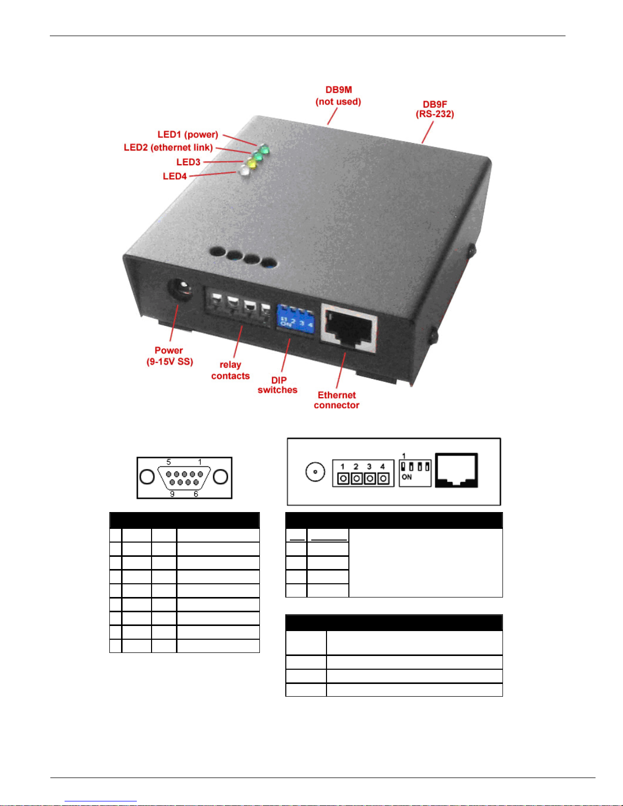
Connector descriptions
Port 1 - DB9F
RS-232 Interface
1 - unused
2
TxD
-->
Transmit Data
3
RxD
<--
Receive Data
4
-
unused
5
GND
---
System Ground
6 - unused
7
CTS
<--
Clear to Send
8
RTS
-->
Request to Send
9 - unused
Note: Connector is wired for using the
prolong cable with PC, check careful
connector pinout for your cabling.
Relay pin descriptions
Pin Contact
1
CH1 A
2
CH1 B
3
CH2 A
4
CH2 B
Function of the contacts depends
on the supplied configuration. For
more about the contact types see
the end of this manual.
DIP switch descriptions
DIP 1
ON = RS-232 SETUP mode
OFF = Ethernet mode
DIP 2
PD4 input, ON = Log. 1
DIP 3
unused
DIP 4
unused
Page 8
IP Relay – 2x relay + RS-232 / Ethernet converter
HW group
June 2006 www.HW-group.com
Page 8 / 28
Using the device
In the following chapter you will learn how to connect the device easily to your PC or company
network, configuring it according to your requirements and setting into service. At the end of this
document we describe controlling the device via NVT commands or IP Relay Control - the
controlling software.
Quick setup
The following process is recommended for a quick setup. For detailed description of all parameters
and commands see chapter called “Parameter description”.
Cable connection
Set DIP1 - DIP4 into OFF position
Connect the IP Relay into Ethernet 10 Mbit or 10/100 Mbit. For direct connection to a PC use a
crossed TP cable. For a connection to a hub/switch/router use classic TP patch cable.
If you wish to connect any RS-232 device to the IP Relay, connect it now, using the supplied Laplink
cable (RS-232 interface is at the DB9F connector).
Connect supplied power adaptor to the grid and plug the connector of the power adaptor into the IP
Relay’s power connector.
If the power supply is OK, the green Power indicator should light up.
If the connection to the Ethernet network is OK, the LINK indicator should light up and go down
according to the rhythm of the data transfer to the Ethernet network (Activity signalization).
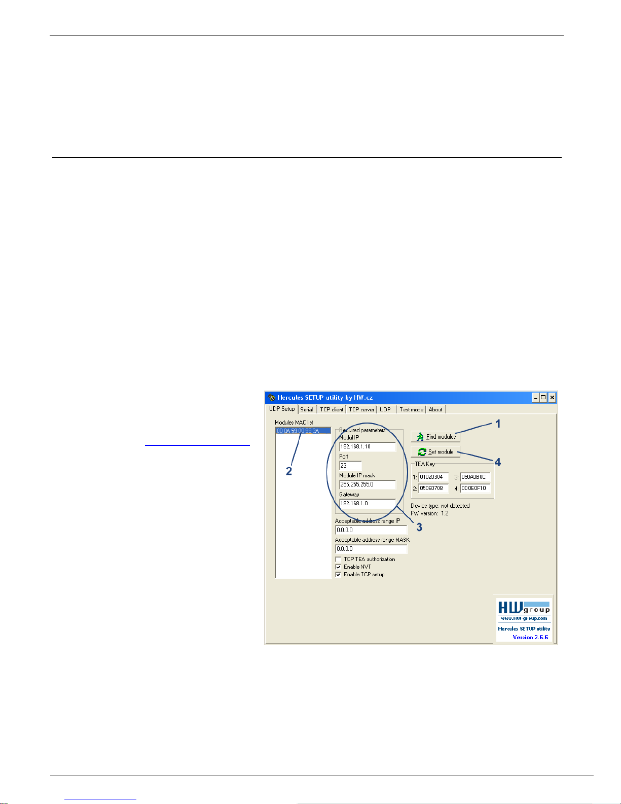
Searching the device in a network
Run the application
„HerculesSetup.exe“ which can be
found in the root directory of the
supplied CD or at www.HW-group.com
1) Click the “Find modules” button
in the “UDP Setup” tab, you can
see the MAC address of the
device in the left column.
2) Click on the MAC address
3) Set the desired parameters (you
must at least set the IP address,
Mask and GateWay).
4) Check the “Enable TCP Setup”
box and click on the “Set
module”. This will save the
network parameters.
Note: If you wish to change these basic parameters (it is necessary to set at least IP address, port,
mask and GateWay), fill the parameters in the proper fields and press the “Set module”.
The device’s IP address and network parameters are now set and you can work with the device.
Page 9
IP Relay – 2x relay + RS-232 / Ethernet converter
HW group
June 2006 www.HW-group.com
Page 9 / 28
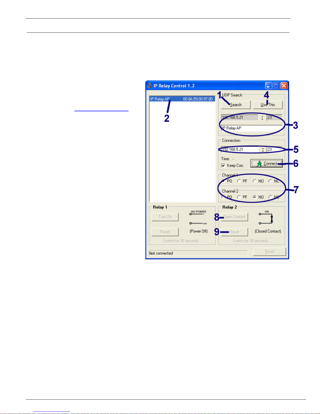
Controlling the IP Relay with the IP Relay Control 1.2 software
IP Relay Control is software intended for easy testing and using the IP relay, which allows
controlling the relay’s contacts by NVT commands through a graphic environment. IPRC is a simple
utility, which does not require installation and besides the device controlling it also allows easy
management of more devices and realization of the Reset function.
Using the IPRC
Run the program “IPRelayControl.exe”
which can be found in the “IP Relay”
directory of the supplied CD or
downloaded from www.HW-group.com.
1) Press the “Search” button from the
“UDP Search” section.
2) Click on he MAC address.
3) The fields beneath the Search
button will be filled with the
configured parameters: IP address,
port and the device name (if
configured).
4) Pressing the “Use This” button will
transfer the IP address and port to
the “Connection” section.
5) If the required IP relay is not
available in the local network, its IP
address and port can be set
manually in the “Connection”
section.
6) By pressing the “Connect” button
set up the connection.
7) Set the proper relay configuration of
the corresponding device using the “Channel 1” and “Channel 2” switches (see the chapter
“Device Versions” at the end of this document). With changing the channels the pictures
representing the relay connection change as well (only if relay’s connected).
8) You can control the relay contacts by pressing the “Turn On”, “Turn Off”, “Close Contact” and
“Open Contact” (depending on the configuration used and the relay status).
9) Pressing the Reset button can change, for a short period of time (30 sec), the relay’s default
state. (The default state means default HW configuration of the IP relay).
Page 10

IP Relay – 2x relay + RS-232 / Ethernet converter
HW group
June 2006 www.HW-group.com
Page 10 / 28
Controlling the IP Relay with HW Virtual Serial Port
Virtual serial port HW VSP includes simple functions for controlling the input/output binary lines of
the devices produced by Hwgroup such as I/O Controller and IP Relay. These additional functions
can be found in the Binary I/O bookmark of the HW Virtual Port Manager program. For more
detailed information about HW Virtual serial port see the
following chapter: HW VSP – Virtual serial port.
1. Install and run the HW VSP.
2. In the UDP Setup tab press the Search modules
button and choose a device’s MAC address from
the Modules MAC list window. The fields of the
Module parameters will be filled by data from the IP
Relay. Pressing the Use this IP button will load the
communication parameters into HW VSP.
3. Switch to the Binary I/O tap and then to the IP
Relay.
4. Pressing the Read Values button will load the
actual state.
5. The On and Off switches can define whether the
relay will be active for Channel 1 or Channel 2 ().
Writing is achieved by appropriate Set button.
While reading and writing there is an indication of
the communication state displayed in the down left
corner of the IP Relay’s window.
6. The Red LED field allows lighting up and turning down the red LED. Writing is achieved by a
proper Set button.
Warning: The buttons allow writing the state of the relay or LED separately. Changing state
of both Relay and LED at once is not possible!
• The Output types table represents the state of the relay’s outputs for its configuration in closed
and open state. (see chapter Device version)
• The item DIP2 displays the state of DIP2 switch, if the PD4 was preset to log. H.
SETUP troubleshooting
• No MAC address has appeared in the „Modules MAC list“ or the device doesn’t
communicate over Ethernet
• Check if the power supply adaptor is connected (the green Power indicator must be lit)
• Your Ethernet network must support 10 Mbit devices.
• Check if you are using the correct TP cable (TP Patch cable for a hub/switch/router
connection, crossed TP cable for direct PC connection.
• Check the configuration of DIP switches of the device (all should be in the OFF position). If
the DIP 1 is in the ON position, the device is in the RS-232 setup mode and does not
communicate over Ethernet. After switching the DIP 1 into OFF position it’s necessary to
restart the device by interrupting the power supply for at least 3 seconds.
• If you are using a firewall, check if it doesn’t block communication with the device.
Page 11

IP Relay – 2x relay + RS-232 / Ethernet converter
HW group
June 2006 www.HW-group.com
Page 11 / 28
Controlling the Relay and LED diodes
Both relays and LED diodes are controlled via NVT commands. It’s a 7-byte binary sequence, which
is sent into the established TCP/IP connection and if it’s received correctly, it’s confirmed by a
similar 7-byte sequence. TCP Connection, by which the relays are controlled, is identical with the
TP connection at RS-232 port but, thanks to the NVT (Network Virtual Terminal), the data from the
serial port are not influenced by these control sequences.
As a further NVT description would exceed the ambit of this manual, you can find the explanation of
the protocol, the commands we use and the RFC2217 extension in the CD enclosed or on
http://www.hw-group.cz/support/nvt/.
Selection of sequences for controlling Relay 1 and Relay 2
In the table bellow you’ll find the description of the particular NVT commands for controlling the
relay and LED diodes. The actual effect of each relay on the terminal board contacts depends on
the contact configuration of the supplied device (PO, PF, NO or NC version). The version of your IP
Relay can be found at the bottom of the box. For more about particular versions of the device see
the end of this manual.
Command description
NVT command
sent from PC
Command confirmation
from IP Relay
Closes Relay 1
NO: Switching contact Ch1 : CLOSES
NC: Break contact Ch1: OPENS
PO: Power supply over break contact Ch1: TURNS THE POWER
SUPPLY OFF
PF: Power supply over break contact Ch1: TURNS THE POWER
SUPPLY ON
FF FA 2C 32 25 FF F0 FF FA 2C 97* DF FF F0
Opens Relay 1
NO: Switching contact Ch1 : OPENS
NC: Break contact Ch1: CLOSES
PO: Power supply over break contact Ch1: TURNS THE POWER
SUPPLY ON
PF: Power supply over break contact Ch1: TURNS THE POWER
SUPPLY OFF
FF FA 2C 32 15 FF F0 FF FA 2C 97* FF FF F0
Closes Relay 2
NO: Switching contact Ch2 : CLOSES
NC: Break contact Ch2: OPENS
PO: Power supply over contact Ch2: TURNS THE POWER
SUPPLY ON
PF: Power supply over break contact Ch2: TURNS THE POWER
SUPPLY OFF
FF FA 2C 32 26 FF F0 FF FA 2C 97* BF FF F0
Opens Relay 2
NO: Switching contact Ch2 : OPENS
NC: Break contact Ch2: CLOSES
PO: Power supply over contact Ch2: TURNS THE POWER
SUPPLY ON
PF: Power supply over break contact Ch2: TURNS THE POWER
SUPPLY OFF
FF FA 2C 32 16 FF F0 FF FA 2C 97* FF FF F0
Lights up LED3 – yellow
FF FA 2C 32 10 FF F0 FF FA 2C 97* 61 FF F0
Turns off LED3
FF FA 2C 32 20 FF F0 FF FA 2C 97* 60 FF F0
Lights up LED4 – red
FF FA 2C 32 11 FF F0 FF FA 2C 97* 63 FF F0
Turns off LED4 – red
FF FA 2C 32 21 FF F0 FF FA 2C 97* E1 FF F0
Lights up LED4 – green
FF FA 2C 32 17 FF F0 FF FA 2C 97* E1 FF F0
Turns off LED4 – green
FF FA 2C 32 27 FF F0 FF FA 2C 97* 6C FF F0
Device’s function verification (query "Are you there?")
The response contains SW version and device’s MAC address
FF F6
<WEB51 HW 6.0 SW 2.I SN
009AF2 #E0>
* This byte depends on the DIP2 configuration and so it can change. For DIP2=ON is the return value 98, for DIP2=OFF it’s 97.
Page 12

IP Relay – 2x relay + RS-232 / Ethernet converter
HW group
June 2006 www.HW-group.com
Page 12 / 28
Example of controlling with the Hercules Setup Utility
For sending the NVT commands you can
also use our Hercules Setup Utility,
actually the „TCP client“ tab. For the
following example we assume you have
the device connected to the Ethernet
network and configured according to your
network parameters – see previous
chapters.
1. Click on the „TCP client“ tab
2. Make sure that the fields „Module
IP“ and „Port“ contain correct
parameters of your IP relay.
3. Click the „Connect“ button
4. Fill the specific field from the
„Send“ section with the desired
NVT command with reference to the table from the previous page
5. Check the field „HEX“ next to the line with the command and press the „Send“ button
6. IP relay reacts according to the sent command and responds by the sequence as depicted
Controllong the red LED using the Hercules Setup Utility
• Connect to the IP Relay according to the previous chapter (using the TCP Client mode)
• Enter this command into one of the „send“ fields:
FF FA 2C 32 11 FF F0
Check the HEX button and send the command using the corresponding button..
• The red LED will light up and IP relay will respond with:
FF FA 2C 97 63 FF F0
Note : The 5th byte (97) can differ according to DIP2 setting.
• You can turn the LED off using this command:
FF FA 2C 32 11 FF F0
• The red LED will turn off and IP relay will respond with:
FF FA 2C 97 E1 FF F0
Note : The 5th byte (97) can differ according to DIP2 setting.
* This byte depends on the DIP2 configuration and so it can change. For DIP2=ON is the return
value 98, for DIP2=OFF it’s 97.
Page 13

IP Relay – 2x relay + RS-232 / Ethernet converter
HW group
June 2006 www.HW-group.com
Page 13 / 28
Setting other parameters of the device
More parameters of the device can be configured either by TCP or RS-232 setup. Both methods will
be described in the following chapter, use the one that fits your application the best.
We assume you have the Hercules Setup Utility program running already and set all the basic
parameters of the device (IP address, port, mask and gateway) as described in previous chapters.
Setting via TCP Setup
Switch to the „TCP Client“ tab.
1. Insert the preset IP address into the
„Module IP“ field.
2. Fill the field „Port“ with „99“, no
matter what port you have choosen for
the communication with the device
(Port 99 is reserved for the TCP
setup).
3. Press the „Connect“ button.
The prompt “WEB51>” should appear in the
„Received / Sent data“ window. Click into this
field and press Enter. The actual parameter
configuration should appear in the window.
Specific parameter is set by choosing the
letter corresponding to the desired option and
it’s value. (e.g. „I192.168.6.8“ for setting the
IP address of the device).
Note: Complete listing of configuration parameters and commands with a detailed description can
be found in the following chapter.
You can see help to any command when you send the commands name together with the question
mark (for example „I? <Enter>“.
After you set all the desired parameters, call the “R” function (R
eboot).
Press the „Disconnect” button to disconnect from the device.
Page 14

IP Relay – 2x relay + RS-232 / Ethernet converter
HW group
June 2006 www.HW-group.com
Page 14 / 28
SETUP using the RS-232 terminal
The description of the configuration using
the supplied software Hercules Setup
Utility. If you cannot use this software, the
device can be set from any RS-232
terminal.
Disconnect the power supply adaptor from
the device.
Set DIP1 = ON, DIP2 = OFF, DIP3 =
OFF, DIP4 = OFF.
Connect the device with supplied RS-232
cable to a PC. Use the Port 1 (DB9F) on
the IP Relay.
Switch to the “Serial” tab of the Hercules
Setup Utility.
1) Set the proper serial port and
communication parameters - 9600
8N1.
2) Click on the „Open“ button.
Connect the power adaptor into the
feeding connector of the IP Relay. The
green Power indicator should light up.
The listing of configuration parameters will
appear in the „Received/Sent data“
window.
Concrete parameter is set by choosing the
letter corresponding to the desired option
and its value. (for example „I192.168.6.8“
for IP address of the device).
Note: Complete listing of the configuration
parameters and commands with detailed
description can be found in the chapter
“description of the configuration
parameters”
You can see help to any command when
you send the commands name together
with the question mark (for example „I?
<Enter>“.
After you set all the desired parameters,
call the “R” function (Reboot).
Close the serial connection with using the
“Close” button.
Note : Do not forget to switch the DIP1 back into OFF position or it would be impossible to
communicate with the device over Ethernet. .
Page 15

IP Relay – 2x relay + RS-232 / Ethernet converter
HW group
June 2006 www.HW-group.com
Page 15 / 28
HW VSP - Virtual Serial Port
Virtual driver of the serial port for Windows is a software instrument that adds a virtual serial
port (e.g. COM5) to the operating system and redirects data from this port to other hardware
port. Nowadays the virtual port is mainly used for connection of the RS-232 serial port via
USB or Ethernet network.
• Runs under Windows 2000 and Win XP.
• If the device supports RFC 2217 (NVT)
you can set parameters of the remote
serial port (baud rate, parity, stop bits).
• Debugging is eased by the possibility of a
recording the communication into a LOG
file.
• It is possible to create more Virtual Serial
Ports on a single computer (COM5,
COM6, COM7...) by running VSP.EXE via
command line.
Using HW VSP with IP Relay
• Run the HW VSP software installation (in the
„HW_VirtualSerialPort” directory on our CD). Do
not forget to check the option to finish the second
part of the installation. When the installation is
finished, make sure to restart your PC.
• Check that NVT is enabled (on the UDP Setup tab
from Hercules utility). If not, enable NVT and save
the configuration.
• Run HW VSP and search for the IP Relay in the
„UDP” bookmark. Choose the MAC address of the
device and click on the „Use this IP” button. Switch
to the „Virtual SP” bookmark. The IP and Port
should be already set.
This searching via UDP Broadcast works only on a
local network. If the IP Relay is installed behind a
router or similar element, the IP address and port
must be filled manually in the „Virtual SP“ tab.
• Choose the serial port you want to create (COM1 –
COM20) and click the “Create COM” button. The frame “LAN status” will show whether
the device has been found and if correct, the virtual serial port is created.
• As you run any application which opens selected virtual port (here it’s COM5) the HW
VSP will link up with the IP Relay, set the remote port according to the opened serial port
(speed, parity, number of bits, handshake) and starts to transfer the data. Some
applications have problems with serial port numbers higher than COM4 but you can use
the original Hyperterminal from Windows, Serial tab from the Hercules setup utility or
Slovene program “Terminal.exe”. These programs are located in the “utils” directory of
our CD.
Page 16

IP Relay – 2x relay + RS-232 / Ethernet converter
HW group
June 2006 www.HW-group.com
Page 16 / 28
Configuration options of the HW VSP
TEA Key frame
You can use the TEA algorithm to secure the TCP/IP access
(you must set the same TEA key on both sides of the
communication).
NVT frame
Enables the RFC2217 detection of our remote ports. Do not
forget to turn on NVT support on the remote device.
• NVT filter – filters NVT commands from the data flow.
• NVT port setup – sends commands to the remote port according to
the VSP settings in your PC. If your terminal program (e.g.
HyperTerminal) changes data transfer speed to 19.200 Bd and this
function is enabled, the VSP driver sends NVT command (according
to RFC2217) to change the remote TCP/IP port’s speed as well.
Keep Connection – keeps the TCP/IP connection opened even after 50
seconds of inactivity.
HW VSP parameters
• log. enabled
VSP driver creates file “C:\serialport.log” for logging all activity of the virtual serial port.
• TCP server mode
Activates VSP as a TCP/IP server. Driver then behaves as a TCP Client/Server = side which
first receives any data switches to the role of a client and opens the connection.
TCP server’s port, which is used as input can be configured in main „Virtual SP” tab and we
recommend using numbers higher than 1025.
• Create port on start VSP
If checked all virtual port will be created automatically on startup of VSP. If you need to create
virtual ports on Windows startup it’s necessary to check the box “Start VSP on boot”.
• Hide on startup
Hides VSP to system tray. Icon can be then found next to the clock.
• Don't create port if ping fail
IP address of the device is tested before creating virtual port. If testing fails the port is not
created.
• Connect to module if port is closed
When checked, you can loose data incoming from remote device, if the virtual serial port isn’t
used by some application.
Start VSP on boot
Adds a path to VSP into register RUN
(HKEY_LOCAL_MACHINE\SOFTWARE\Microsoft\Windows\CurrentVersion\run) in
Windows. VSP is then run on Windows startup.
HW VSP – command line parameters
HW VSP can be also started through specific parameters from command line. This way more virtual
serial ports can be created at once. Detailed description of parameters can be found at our website
www.HW-group.com.
Example: CharonVirtualCom.exe -R -i192.168.6.21:23 -c5 -S0 -N1 -Nf -Np -H1
Page 17

IP Relay – 2x relay + RS-232 / Ethernet converter
HW group
June 2006 www.HW-group.com
Page 17 / 28
IPRC – IP Relay Control
IP Relay Control is software intended for easy testing and using IP relays of the HW
Group production. It allows controlling the relay contacts via NVT commands in the
graphical environment. IPRC is a small utility which does not require installation and
besides the IP relay controlling it also allows simple management of more devices and
easy realization of the Reset function.
Basic characteristics of IPRC
• Simple graphic environment for Windows
95/98/ME/2000/XP.
• Support of all available IP relay
configurations.
o Power On (PO);
o Power Off (PF);
o Normally Open (NO);
o Normally Close (NC);
• Searching IP relays in the local network by a
UDP Broadcast
• Allows assigning the name to the IP relay
depending on an IP address.
• Allows prolonged status change by buttons:
o Turn On – turn on the power supply;
o Turn Off – turn the power supply off;
o Close Contact – close the contact;
o Open Contact – open the contact.
• The Reset function allows short-term (30 sec)
status change.
• Shows duration of the running connection.
• The Read button for loading the actual IP
relay state.
• Writing the executed operation into a log.
In the upper left section of the application the list of found devices and their MAC addresses is
displayed. You can search for the individual devices within the local network by the Search button in
the UDP Search section. By choosing appropriate MAC address the actual assigned IP address
and port will be written into the fields below the Search button. You can write a text-based device
signature (up to 255 chars) into the field below the IP address, which can easily identify the
particular IP relay in the network of more devices.
By the “Use This” button is either the corresponding signature written into the configuration file of
the IP Relay Control and the IP address and port transferred into the relevant fields of the
Connection section.
The Connection section serves for opening and closing a TCP connection with the corresponding
IP relay module. By the Connect, (or Disconnect) button you can create or dissolve this connection.
The check box named Keep Connection hold stable TCP connection until Disconnect.
There is channel type autodetection, if it’s fault, you can define Channel’s type manually by the
Channel 1 and Channel 2 switches, which allow assigning four possible configurations to the
particular channels Power On (PO), Power Off (PF), Normally Open (NO) and Normally Close (NC).
Page 18

IP Relay – 2x relay + RS-232 / Ethernet converter
HW group
June 2006 www.HW-group.com
Page 18 / 28
Main relay attendance is then performed in the Relay 1 and Relay 2 sections by buttons:
• Turn On – turn on power supply;
• Turn Off – turn the supply off;
• Close Contact – close contact;
• Open Contact – open contact.
For better lucidity the actual relay states are also shown graphically as schematic marks, which can,
as well, serve to verify the configuration.
Note: Immediate changing of the schematic pictures representing the relay connection works
only if the IP relay is connected. In other case their exchange will not proceed until the TCP
connection is established.
While the buttons allow switching the device into desired state ad infinitum, in many cases the relay
will be used mainly as a remote reseter for the necessary short-term status change of the controlled
device. This is achieved by the Reset button, which ensures short-term (30 second long) status
change. This assure that the controlled relay will be brought back to the default state regardless the
previous contact state, set by the user.
Note : The default state means the default IP relay HW configuration.
The Read button is intended for check loading of the actual IP relay state. On the left of it is the
control line, which writes out the actual state of the required operation.
IP Relay Control also contains the logging function of the performing operations which writes, in
text format, into the log file the individual operations, performed by the IP relay devices together with
time information. This serves to verify, in return, if the status change was or was not evoked by the
IP relay.
(II) 19:23:35 192.168.5.21: Connecting...
(II) 19:23:38 192.168.5.21: Connected
(II) 19:23:38 192.168.5.21: Read state of relay 1 (sent FF FA 2C 32 30 FF FO)
(II) 19:23:38 192.168.5.21: Read state of relay 2 (sent FF FA 2C 32 30 FF FO)
(II) 19:23:38 192.168.5.21: State output pins acknowledge (received FF FA 2C 97 31 FF F0)
(II) 19:23:38 192.168.5.21: State output pins acknowledge (received FF FA 2C 97 31 FF F0)
(II) 19:23:41 192.168.5.21: Read state of relay 2 (sent FF FA 2C 32 30 FF FO)
(II) 19:23:41 192.168.5.21: State output pins acknowledge (received FF FA 2C 97 31 FF F0)
(II) 19:23:45 192.168.5.21: Disconnected
(II) 19:23:46 192.168.5.21: Connecting...
(II) 19:23:46 192.168.5.21: Connected
(II) 19:23:46 192.168.5.21: Read state of relay 1 (sent FF FA 2C 32 30 FF FO)
(II) 19:23:46 192.168.5.21: Read state of relay 2 (sent FF FA 2C 32 30 FF FO)
(II) 19:23:46 192.168.5.21: State output pins acknowledge (received FF FA 2C 97 31 FF F0)
(II) 19:23:46 192.168.5.21: State output pins acknowledge (received FF FA 2C 97 31 FF F0)
(II) 19:23:53 192.168.5.21: Channel 1 set POWER from ON to OFF (output pin Hi, sent FF FA 2C 32 25 FF F0)
(II) 19:23:53 192.168.5.21: Channel 1 set LED to OFF (output pin Hi, sent FF FA 2C 32 20 FF F0)
(II) 19:23:53 192.168.5.21: State output pins acknowledge (received FF FA 2C 97 11 FF F0)
(II) 19:23:53 192.168.5.21: State output pins acknowledge (received FF FA 2C 97 10 FF F0)
(II) 19:23:54 192.168.5.21: Channel2 set CONTACTfromOPEN to CLOSE(output pin Lo, sent FF FA 2C 32 16 FF F0)
(II) 19:23:54 192.168.5.21: Channel2 set LED to ON (output pin Lo, sent FF FA 2C 32 17 FF F0)
(II) 19:23:54 192.168.5.21: State output pins acknowledge (received FF FA 2C 97 50 FF F0)
(II) 19:23:54 192.168.5.21: State output pins acknowledge (received FF FA 2C 97 D0 FF F0)
(II) 19:24:26 192.168.5.21: Keep connection (command NOP)
(II) 19:25:06 192.168.5.21: Keep connection (command NOP)
(II) 19:56:26 192.168.5.21: Keep connection (command NOP)
(II) 19:57:06 192.168.5.21: Keep connection (command NOP)
(II) 19:57:13 192.168.5.21: Disconnected
(II) 20:13:29 192.168.5.21: Connecting...
(II) 20:13:29 192.168.5.21: Connected
(II) 20:13:29 192.168.5.21: Read state of relay 1 (sent FF FA 2C 32 30 FF FO)
(II) 20:13:29 192.168.5.21: Read state of relay 2 (sent FF FA 2C 32 30 FF FO)
(II) 20:13:29 192.168.5.21: State output pins acknowledge (received FF FA 2C 97 D0 FF F0)
(II) 20:13:29 192.168.5.21: State output pins acknowledge (received FF FA 2C 97 D0 FF F0)
(II) 20:13:30 192.168.5.21: Read state of relay 1 (sent FF FA 2C 32 30 FF FO)
(II) 20:13:30 192.168.5.21: Channel 1 set LED to ON (output pin Lo, sent FF FA 2C 32 10 FF F0)
(II) 20:13:30 192.168.5.21: State output pins acknowledge (received FF FA 2C 97 D0 FF F0)
Page 19

IP Relay – 2x relay + RS-232 / Ethernet converter
HW group
June 2006 www.HW-group.com
Page 19 / 28
Description of configuration parameters
In this chapter you can find the detailed description of all possible configuration parameters.
Information on the device configuration can be found in the chapter “QUICK Setup of the device”.
Default device configuration
This is the listing of a standard configuration of every supplied IP Relay. This can be refreshed
anytime by “D0” or “D1”commands in the setup mode. Description of the device configuration and
commands entry can be found in the chapter “Setting other parameters of the device”.
*** HW-group.com HW 6.0 SW 2.M #01 ***
MAC Address 00:0A:59:00:99:3A
=========== IP Setup ============
I: Address 192.168.6.200
J: Port 23
M: Mask 255.255.255.0
G: Gateway 192.168.6.254
===== In IP access filter ======
W: Address 0.0.0.0
N: Mask 0.0.0.0
X: Port 0.0
Y: Port Mask 0.0
== Active (Client/Server) mode ==
S: Send to IP PASSIVE mode
U: Port 23
T: IP mode TCP
V: NetworkVirtualTerminal On
K: Keep connection Off
E: Erase buffer on None
========= Serial Setup ==========
&B: Speed 9600
&D: Data bits 8
&P: Parity NONE
&V: Variable Parity Off
&S: Stop bits 1
&C: Flow Control NONE
&R: RS485/RS422 control RTS = On [+8V]
&T: Serial Line Timeout 0 - Off
&G: Char. Transmit Delay 0 - Off
&H: Tx Control Tx FULL duplex
======== Security Setup =========
%A: TCP autorisation Off
%K: TEA key 0:01:02:03:04 1:05:06:07:08 2:09:0A:0B:0C 3:0D:0E:0F:10
%S: TCP/IP setup On
======= I/O Control Setup =======
#T: Trigger AND mask 255
#A: Power Up INIT 189
#B: Power Up AND mask 255
#C: Power Up OR mask 0
#D: Power Up XOR mask 0
#X: KEEP mask 0
#Y: AND mask 255
#Z: OR mask 0
#W: XOR mask 0
============ Other ============
D: Load/Save Settings from/to Flash
R: Reboot
Page 20

IP Relay – 2x relay + RS-232 / Ethernet converter
HW group
June 2006 www.HW-group.com
Page 20 / 28
(IP requesting access AND N) = W
If this condition is valid, you can access the
device (AND is binary multiplication).
Device network parameters
MAC Address 00:0A:59:00:95:6C
MAC address is a unique network device address in the Ethernet and it is always factory-preset.
You can find it on the label inside the device. Using this address, the devices can be distinguished
for example in the UDP mode of the configuration program.
Note: The address respects restoring of the default configuration with the „D0” command.
I: Address 192.168.6.15
Configuration of the device’s IP address.
J: Port 23
Configuration of the relay's communication port –
range: 1 .. 19.999.
Port 99 is used for TCP configuration, if
supported by the version and enabled in the
setup.
M: Mask 255.255.255.0
Configuration of the IP mask for the local network.
All IP addresses outside the area delimited by the
device's own IP address and this mask will be
accessed via Gateway.
G: Gateway 192.168.6.254
Address of the gateway that provides access to
outside networks, as defined by the IP address and
the mask.
====== In IP access filter ======
W: Address 0.0.0.0
IP address of a network or computer that is allowed to communicate with the device. This value must
result from multiplying the remote IP address and the restriction mask (option N), otherwise the device
does not react.
N: Mask 0.0.0.0
This mask restricts addresses that can communicate with the device. Security can be greatly
enhanced by setting a fixed address or a suitable restrictive mask that disallow communication with
unauthorized parties.
X: Port 0.0
Configuration of the communication port – range 1 .. 19.999.
Y: Port Mask 0.0
This restricts TCP ports that can communicate with the Device.
IP address, Mask and Gateway description:
Ethernet device communicates:
• On local network segment
You don’t need a Gateway, but IP
addresses of both devices must be in the
range allowed by the Mask setting. If you
set the Mask to 255.255.255.0 the IP
addresses may differ only in the last byte.
• Outside local network – using
Gateway, which is positioned in the range
of IP addresses allowed by the mask.
You can also restrict the IP address range
using the “In IP Setup“ commands. We
recommend keeping this parameter on
0.0.0.0. for debugging.
Page 21

IP Relay – 2x relay + RS-232 / Ethernet converter
HW group
June 2006 www.HW-group.com
Page 21 / 28
Parameters of TCP and UDP connection
====== Active (Client/Server) mode ======
S: Send to IP 192.168.0.252
The IP address and the port of the opposite side that will be connected for the data transmission from a
serial port. Setting to 0.0.0.0 will switch the converter into a passive mode.
U: Port 23
Configuration of the device's communication port – range: 1 .. 19.999.
Note: If you are using communication via UDP it’s necessary to enter the address of the opposite
side here. The converter does not initiate the connection so the responses are sent to this address!
T: IP mode TCP
Switches between the TCP and UDP protocols. UDP is faster but packets can be lost or delivered out of
order. Hence it is suitable for communication only on a local network segment in request-reply mode,
usually for converting a RS-485 communication. UDP communication is difficult to debug because no
simple PC terminal, like TELNET terminal for TSP/IP connection, is available.
In TCP it is possible to use the NVT commands and a TEA encryption. Responses of the converter
in case of question/answer protocols in the TCP mode can be slower up to 40% caused by setting
up the connection.
IP mode: 0: TCP / 1: UDP
V: NetworkVirtualTerminal Off
Network Virtual Terminal allows the interpreting of Telnet protocol sequences including certain
RFC2217 extensions, enabling on-the-fly changes of serial port parameters (speed, parity, ...).
NVT description can be found on our website >> „Support & download” >> „NVT (Network Virtual
Terminal) protocol description”.
When communicating with the serial port using telnet, e.g. with the TeraTerm program, this option
should be turned on. Otherwise, telnet control commands (seen as "junk") intended for configuration
negotiation at the beginning of the communication are forwarded to the serial port. If you don't want
to use this option, set your client to RAW communication mode.
0: Off (don't use telnet control code, pass through to serial port)
1: On (accept telnet control code)
K: Keep connection Off
This option allows keeping the connection alive with sending NOP commands, because TCP
automatically closes the connection after 50 seconds of inactivity. NVT must be enabled for this
parameter to work.
0: no keep connection (preferred)
1: keep connection
E: Erase buffer on Open connection
Option to clear the internal Device buffer whenever a connection is established or closed. This
option is useful e.g. if your device periodically says “I'm alive” and you don't want to waste time
retrieving these notifications from the buffer.
0: none
1: Close TCP/IP connection
2: Open TCP/IP connection
3: Open & Close TCP/IP connection
Page 22

IP Relay – 2x relay + RS-232 / Ethernet converter
HW group
June 2006 www.HW-group.com
Page 22 / 28
Serial port parameters
====== Serial Setup ======
&B: Speed 9600
Configuration of the communication speed for the serial line, range 50..115.200 Bd, step 50 Bd. To set
9600 Bd enter: „&B9600”.
&D: Data bits 8
Number of data bits for the serial transfer. Possible options:
7: 7 bits / 8: 8 bits – call „&D8“.
&P: Parity NONE
Parity of the serial asynchronous communication:
N: none / O: odd / E: even / M: mark / S: space
&V: Variable Parity Off
Activation of 9-bit data transfer.
0: Off / 1: On
&S: Stop bits 2
Number of stop bits for the RS-232 serial line. It’s possible to set 1 or 2 stop bits.
&C: Flow Control NONE
Serial data flow control.
1: none - no control, RTS - see &R.
2: RTS/CTS –RTS/CTS control
3: Xon/Xoff - SW data flow control.
&R: RS485/RS422 control
Defines idle level of the output RTS pin. Important for devices powered from RTS or for add-on RS485
Devices that use RTS to switch direction. Especially for the internal RS485 module, the “HW echo”
option should be on. This means that the receiver reads the data back from RS485 and generates
hardware echo from the actual RS485 bus.
0: RTS = Low [+8V] (recomended for non RS485/422 mode)
1: RTS = High [-8V]
2: TxRTS HW echo ON
3: TxRTS HW echo OFF
&T: Serial Line Timeout 0 – Off
Specifies how long the Device waits after receiving the last character before wrapping up the
data in a packet and transmitting them. The timeout is specified as the number of characters and
displayed as the number of chars as well as the time according to the given serial communication
speed. If the speed changes, the time is also changed but the number of characters defining the
timeout is not (10 znaků pro 9600 je cca 11 ms, ale pro 19.200 Bd je to 5,7 ms).
Page 23

IP Relay – 2x relay + RS-232 / Ethernet converter
HW group
June 2006 www.HW-group.com
Page 23 / 28
&G: Char. Transmit Delay 0 – Off
For controlling units with small RS232 buffer, it is sometimes advantageous to keep relatively high
baud rate but insert delays between individual characters. The delay is defined in milliseconds and
it is defined as the time between the starts of individual characters; so, for 2400 Bd a 2ms delay has
no effect since the character starts are 2.4 ms apart.
&H: Tx Control Tx FULL duplex
When HALF duplex is activated, the Device assumes unidirectional medium connected to the serial
line (e.g. RS485) and won't start transmitting data while receiving.
0: FULL duplex
1: HALF duplex (RS485)
Other device parameters
===== Security Setup ======
%A: TCP autorisation Off
Activates TEA authorization, which is requested from the remote side after the connection is
established.
0: TEA authorisation Off
1: TEA authorisation On
%K: TEA key 0:01:02:03:04 1:05:06:07:08 2:09:0A:0B:0C 3:0D:0E:0F:10
To set the TEA key, use the “%K” option. Set 16 bytes in quadruples using four hexadecimal values
separated with colons. The first string defines 0-3rd quadruple of bytes. So, to set the last 4 bytes to
the displayed value, use „%K 3:0D:0E:0F:10“.
%S: TCP/IP setup On
Allows or denies the remote configuration using TCP setup on port 99.
==== I/O Control Setup ====
#T: Trigger AND mask 0
#A: Power Up INIT 49
#B: Power Up AND mask 0
#C: Power Up OR mask 0
#D: Power Up XOR mask 0
#X: KEEP mask 0
#Y: AND mask 0
#Z: OR mask 0
#W: XOR mask 0
From a whole I/O Control Setup section the IP relay only uses the #A: Power Up INIT command,
which can affect directly the states of output relays on the device reset and thus compensate an
improper relay configuration. Parameter #A is inserted as a DECIMAL value of the IP relay’s
controlling 8-bit port.
Page 24

IP Relay – 2x relay + RS-232 / Ethernet converter
HW group
June 2006 www.HW-group.com
Page 24 / 28
Table containg #A parameter values for particular IP Relay channel’s variations.
CH1 / CH2
Ordering numer YZ*
#A
PO / NO
13 49
PO / NC
14 241
PF / NC
24 208
PF / NO
23 10
NC / PO
41 241
NC / PF
42 49
NO / PO
31 208
NO / PF
32 10
NO / NC
34 208
NO / NO
33 10
NC / NC
44 241
NC / NO
43 49
PO / PO
11 241
PO / PF
12 49
PF / PO
21 208
PF / PF
22 10
The #A value represents the decimal value of the controlling 8-bit IP relay port. It’s actually a
decimal formulation of the hexadecimal value of 5-byte controlling NVT command for controlling the
IP relay (see chapter “Selecting sequences for controlling Relay 1 and Relay 2”). You can get it also
by the means of the Test Mode of the Hercules Setup Utility.
* - Device version derived from the product signature (see chapter “Device versions”). It represents
the Y and Z letters or the product signature.
** - Standard configuration
========= Other =========
D: Load/Save Settings from/to Flash
The “D0“ option loads saved configuration through „D2“. The “D1” option sets the IP Relay’s default
factory values.
R: Reboot
Software reset of the IP Relay. Necessary e.g. for changing the IP address etc.
Page 25

IP Relay – 2x relay + RS-232 / Ethernet converter
HW group
June 2006 www.HW-group.com
Page 25 / 28
Setup example
If you need to send all data from
the serial line to the opposite
side, use:
*L: Trigger Length 0
*P: Post Trigger Length 0
*S: Start Trigger Pattern 0.0.0.0
*M: Start Trigger Mask 0.0.0.0
*X: Stop Trigger Pattern 255.0.0.0
*Y: Stop Trigger Mask 255.0.0.0
*E: Max. Start-Sto
p
Length 200
(The 4 input bytes of data AND *M) = *S
(The 4 input bytes of data AND *Y) = *X
UDP/IP mode settings
If you select „T: IP mode UDP”, the device will communicate with the remote side using
unacknowledged UDP packets. Also, the following menu appears in the setup.
IMPORTANT: You can’t control relay outputs over UDP/IP!
==== Trigerring Setup =====
*L: Trigger Length 1
Numbers of bytes of the starting and ending packet trigger condition. Allowed values are from 0
to 4. If the lengths of your start and stop triggers differ, use the trigger mask and don't forget to
include the masked characters in the lengths - even though they contain actual frame data.
*P: Post Trigger Length 0
In some protocols, checksum or other info follows the stop trigger. This value defines the number
of characters after the stop trigger that should be included in the packet. If the start and stop
triggers are equal, this value specifies packet length without the 0..4 bytes of start trigger.
*S: Start Trigger Pattern 58.0.0.0
Start trigger for packet transmission. Four bytes are set but only the number of bytes specified in
“L: Trigger Length” is considered.
*M: Start Trigger Mask 255.0.0.0
Mask of the start trigger. Masking works similarly to the Ethernet netmasks using a bitwise AND.
Value of 255 means that the tested character must be equal to the character specified in “*S: Start
Trigger Pattern”. For example, to start the transfer with any control ASCII character (0..31d) use
0.0.0.0 for the trigger pattern, 224.0.0.0 for the mask and 1 for the length. If you set both the character
and the mask to 0 the trigger activates for any character.
*X: Stop Trigger Pattern 10.0.0.0
Sets the stop trigger for sending data to the Ethernet.
*Y: Stop Trigger Mask 255.0.0.0
Mask of the stop packet trigger for serial line data. For
example, the settings displayed here are intended for
transferring data in the IntelHEX format over RS485. The start
trigger is a colon and the transfer is terminated after receiving
the control character <LF> (0Ah = 10d).
*E: Max. Start-Stop Length 999
Maximum number of characters sent after the START trigger,
if the STOP trigger is not found sooner. After transmission,
another START trigger is expected. Essentially, this is a
“timeout” specified as the number of characters.
Page 26

IP Relay – 2x relay + RS-232 / Ethernet converter
HW group
June 2006 www.HW-group.com
Page 26 / 28
Application hints
Security
For raising the security of data transfer in TCP mode it’s possible to authorize both sides on
establishing any TCP/IP connection via TEA 128 algorithm with symmetric signature. The
configured password of both sides then won’t go throughout the network. This option is possible
only for TCP/IP connection. UDP mode is designed only for local networks. Detailed description of
TEA can be found in the handbook “Programming of Ethernet Applications” on our website.
Extension of the timeout connection
Since the converter supports only one connection at the moment it’s necessary to secure the
timeout for this connection. Standard limit after which the connection is terminated in case of no
data flow is 50s. With regard to the routine it’s possible to enable option „K: Keep connection“,
which in 10-second intervals sends the NOP command into the open NVT connection.
Network Virtual Terminal
Learn how to use Network Virtual Terminal in your application. Basically the NVT is a system on which
TELNET protocol works. It’s simple and transparent way of handing down the setup information which is
compatible with all sorts of RFC and above all with RFC2217 for remote control of serial port.
Free application software
Use supplied free software for configuration or inspiration for creating drivers. Detailed description
or routines, TEA encoding and our NVT implementation can be found on our web.
• Borland C++ – example of
communication over TCP/IP a NVT
(TCP Client).
• Borland C++ – TCP server solution
example.
• Delphi – example of communication
over TCP/IP a NVT (TCP Client).
• JAVA – example of communication via
TCP/IP – NVT (TCP Client).
• PHP – example of device
communication over TCP/IP – NVT
(TCP Client).
• Visual Basic – example of device communication over TCP/IP a NVT (TCP Client).
Page 27

IP Relay – 2x relay + RS-232 / Ethernet converter
HW group
June 2006 www.HW-group.com
Page 27 / 28
Mechanical dimensions
The device is situated in a sturdy metal box. According to the ordered version of the device, the “L”
plate for wall mounting or removable brackets for a DIN molding are available.
Mounting profiles depending on the ordered version
For the descriptions of the variations that can be ordered see the end of this manual.
• L – Enclosure has got rubber stands but the package also contains already quoted
2 metal L-plates for wall attachment
• D – Enclosure contains rubber stands but the package includes removable mounting for
a DIN molding which is to be attached from below, in the middle of the plate.
Page 28

IP Relay – 2x relay + RS-232 / Ethernet converter
HW group
June 2006 www.HW-group.com
Page 28 / 28
Device versions
IP Relay can be ordered in several versions, which differ with contact’s configuration as well as with
mounting accessories. Please check the product website to choose which output configuration and
related Ordering ID (Purchase number) do you need.
Contact
HW group s.r.o,
Rumunska 26 / 122
Prague 2, 120 00, Czech Republic, Europe
Tel. +420 222 511 918
Fax. +420 222 513 833
http://www.HW-group.com
 Loading...