

Page 1
I/O Controller 2 Manual
HW group
www.HW-group.com
1/ 42
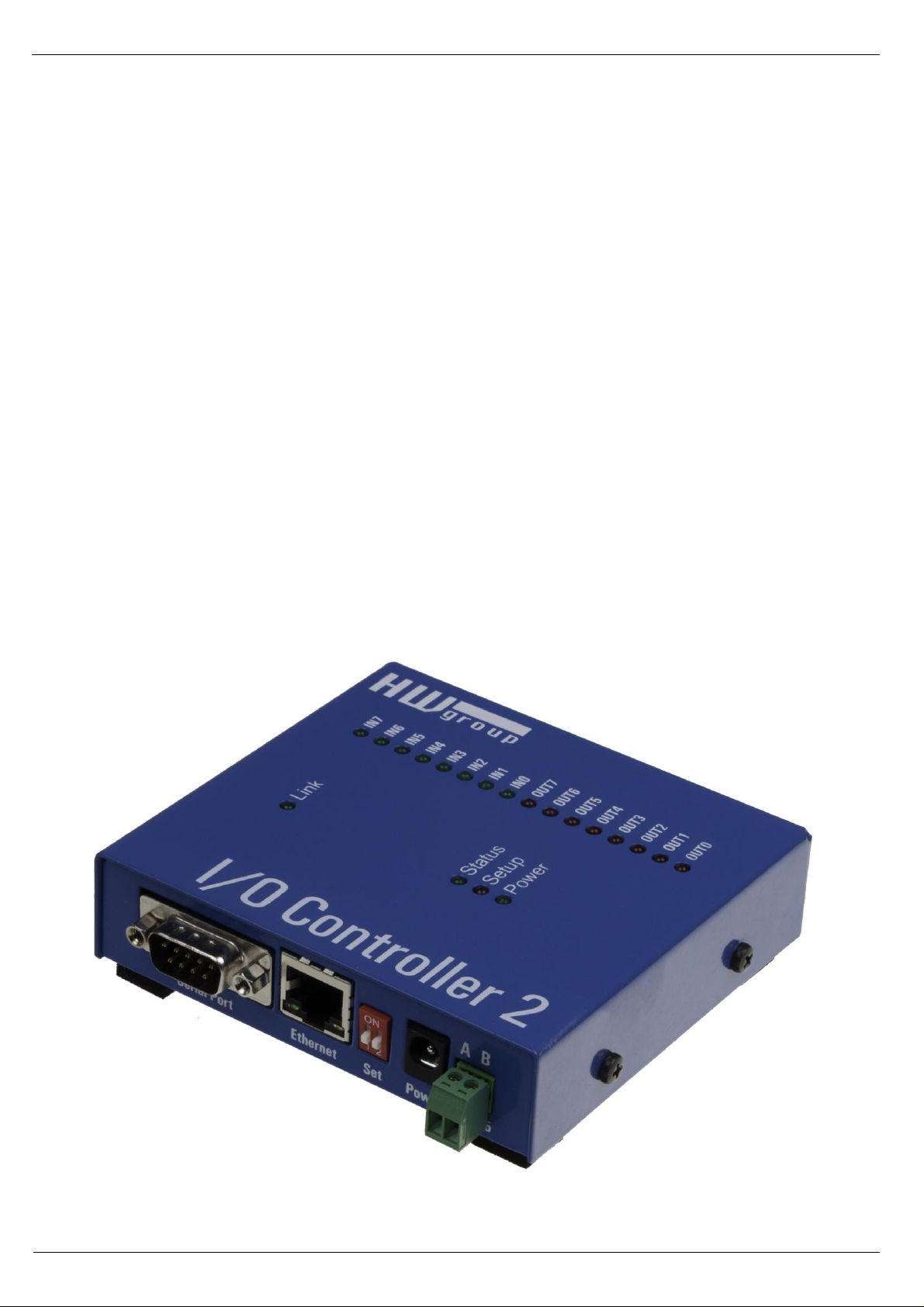
I/O Controller 2
MANUAL
Page 2

I/O Controller 2 Manual
HW group
www.HW-group.com
2/ 42
Safety information
The device complies with regulations and industrial standards in force in the Czech Republic and the
European Union. The device has been tested and is supplied in working order. To keep the device in
this condition, it is necessary to adhere to the following safety and maintenance instructions.
The device must not be used in particular under any of the following conditions:
• The device is noticeably damaged
• The device does not function properly
• Unfastened parts can move inside the device
• The device has been exposed to moisture or rain
• The device has been serviced by unauthorized personnel
• The power adapter or power supply cable are noticeably damaged
The manufacturer warrants the device only if it is powered by the supplied power adapter or an
approved power supply.
Page 3
I/O Controller 2 Manual
HW group
www.HW-group.com
3/ 42
I/O Controller 2
Ethernet – RS-232/485 + inputs and outputs
I/O Controller 2 is an Ethernet-enabled device with 8 digital inputs,
8 digital outputs and a RS-232/485 serial interface.
All interfaces are accessible over TCP/IP using a M2M
protocol.
Two devices can be connected against each other
(Box-2-Box mode) in order to extend the digital and
RS232 signals over the computer network.
Basic features
• 1x full RS-232 or RS-485 serial port accessible over the Ethernet.
• The remote port can be controlled with a virtual driver for Windows just like, for example,
COM 5 (a Windows XP / Vista / Windows 7 / Server 2003 / Server 2008 / x64 driver is
available free of charge). Compatible with RFC2217.
• 100 Mbps Ethernet interface – 100BASE-Tx, RJ 45
• Support for TCP/IP terminal, TELNET – NVT type (Network Virtual Terminal)
• Two devices can „tunnel“ the serial port, 8 inputs and 8 outputs over the Ethernet
• Web-based interface for configuration
• Wide range of supported serial interface parameters:
• Communication speed configurable from 300...115200 Bd
• Handshake (CTS/RTS, Xon/Xoff, none)
• Full serial port (Cannon DB9M - RxD, TxD, CTS, RTS, DSR, DTR, RI, CD, GND)
• Support for 7th to 9th parity bit (9th parity bit transferred over the Ethernet)
• SDK (Software Development Kit) is available for the device with examples for MS Visual
Basic, Delphi, Borland C++, JAVA, PHP and more
Page 4

I/O Controller 2 Manual
HW group
www.HW-group.com
4/ 42
Technical specifications
RS-232 serial port
+ Data bits
7 or 8 or 9
+ Stop bits, parity
1 or 2, None / Odd / Even / Mark / Space parity
+ Baudrates
50..115.2 kBd – entire range
+ Data flow control
XON/XOFF, CTS/RTS, None
+ Interface
1x DB9M (RxD, TxD, CTS, RTS, DSR, DTR, RI, CD, GND)
+ Implemented RS-232 signals
RxD, TxD, CTS, RTS, DSR, DTR, RI, CD
RS-485 serial port
+ Termination
None (We recommend external termination 120-470Ω)
+ Isolation
RS-485 line not optocoupled to the device’s power supply
- electrically isolated RS-232/485 to Ethernet (1000 V)
Digital inputs & outputs
+ Input type
Dry contact input
+ Logic LOW voltage
0 .. 3V
+ Log. HIGH voltage threshold / “on” current
from 5V / 5mA to 20V / 25mA
+ Max. input voltage and current
up to 40V / 50mA / 1 second
+ Isolation Voltage
max. 50V to power supply
+ Sampling period
10 ms
+ SW control of inputs and outputs
Inputs and Outputs controlled over a NVT-based M2M protocol
(extended RFC2217) – short 7-byte binary commands over TCP/IP
+ Output type
Darlington transistors with common emitter, suppression diodes
max. 50V, max. 500mA / 1 output and max. 1500mA / all 8 outputs
Ethernet port
+ Interface
RJ45 100BASE-T / 100 Mbit/s
+ Compatibility
Ethernet: Version 2.0/IEEE 802.3
+ Supported protocols
IP: ARP, TCP + NVT (Network Virtual Terminal)
+ TCP connection closing
Data – 5s timeout (with NVT – ACK/NOP support)
Physical parameters & Environment
+ Temperature & humidity
Operating: 0 – 65 °C (32 – 149 °F)
Storage: -10 to 85°C (14 to 185°F), humidity 5 to 95 %
+ Power supply requirements
8-30V / Max. device current consumption 200 mA DC
- barrel (coaxial) power connector, GND on the shield
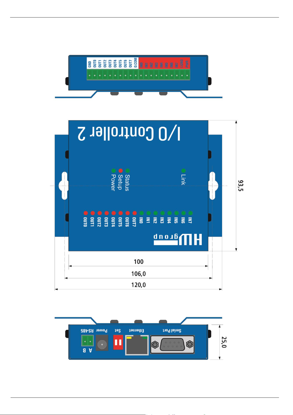
+ Dimensions / Weight
120 x 94 x 25 [mm] (H x W x D) / 260 g
Note: This parameter table is only indicative.
For a valid table, see the specifications for the particular device model.
Page 5
I/O Controller 2 Manual
HW group
www.HW-group.com
5/ 42
Page 6
I/O Controller 2 Manual
HW group
www.HW-group.com
6/ 42
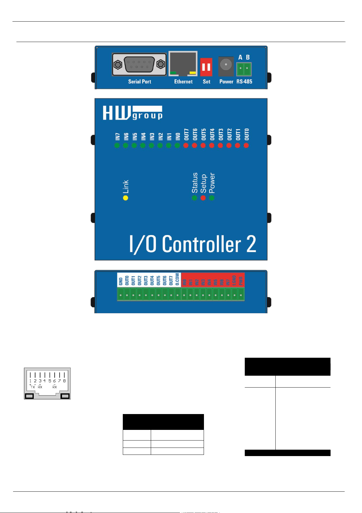
Connectors
Connector pinout
RS-485 Port
Pin
Signal
A
+ (A>B)
B
-
RS-232 Port
Pin
Signal
1 <- CD
2 <- RxD
3 -> TxD
4 -> DTR
5 -- GND
6 <- DSR
7 -> RTS
8 <- CTS
9 <- RI
Cannon 9 - Male
Power LINK
Page 7

I/O Controller 2 Manual
HW group
www.HW-group.com
7/ 42
DIP 1
DIP 2
Function
ON
OFF
RS-232 Setup mode (9600 8N1) Ethernet is disabled
OFF
OFF
Serial port in the RS-232 mode
OFF
ON
Serial port in the RS-485 mode
check the &R and &H parameters (recommended: &R3 &H1)
LEDs:
Power – green ..................................... External power connected
LINK – amber .................................... Ethernet interface activity
Status – green ..................................... Device starting up, firmware upgrade
Setup – red ......................................... Device in serial Setup mode
INx – green ......................................... Input x is closed
OUTx – red ......................................... Output x is closed
Page 8

I/O Controller 2 Manual
HW group
www.HW-group.com
8/ 42
Digital Inputs & Outputs wiring
• GND – device ground.
• PWR – device power (max. 200 mA).
The device can be powered from barrel power connector (front panel) or from the I/O
connector PWR + GND pins (200 mA internal fuse = suitable only for testing purposes).
• I.GND – common ground for optocouplers.
• I.0 to I.7 - 8 optocoupled inputs 5-20V
All 8 inputs are realized using common ground optocouplers (I.GND pin). The pins can then
be controlled using the contacts together with the POWER pin, which has the power adaptor
voltage (connect I.GND with GND).
Warning: The digital input voltage range is 5 -20V, but be careful for max total current thought
I.GND pin which is 200mA for all digital inputs (cca 25 mA per singe Digital Input).
• O.COM (Common) – Overvoltage output connected to the plus pole of the power source. This
can be useful when you want to control a relay from this output.
• O.0 to O.7 - 8 open collector outputs, with common diode overvoltage protection.
The outputs a realized using 8 open collector transistors. Two outputs are internally connected
to a relay, which contacts are also led out to the device’s connector. The protecting diodes are
connected to the “common” pin, which should be connected to the plus pole of the next device
(for example a relay). This way the pins can be protected against load peaks.
PIN
Description
8x INPUTS
GND
Ground
1
OUT0
Output transistor 0
2
OUT1
Output transistor 1
3
OUT2
Output transistor 2
4
OUT3
Output transistor 3
5
OUT4
Output transistor 4
6
OUT5
Output transistor 5
7
OUT6
Output transistor 6
8
OUT7
Output transistor 7
9
O.COM
Common wheeling diodes
10
8x OUTPUTS
IN0
Input 0 (5-15V)
11
IN1
Input 1 (5-15V)
12
IN2
Input 2 (5-15V)
13
IN3
Input 3 (5-15V)
14
IN4
Input 4 (5-15V)
15
IN5
Input 5 (5-15V)
16
IN6
Input 6 (5-15V)
17
IN7
Input 7 (5-15V)
18
I.GND
Opto-couplers ground
19
PWR
Ext. power supply
20
1
20
Page 9
I/O Controller 2 Manual
HW group
www.HW-group.com
9/ 42
Quick SETUP
Connecting the cables
• Connect the supplied power
adapter to an electrical outlet.
• Set DIP1 and DIP2 to OFF.
• Connect the device to the
Ethernet.
• Connect the power adapter to
the power connector at the
device.
• If the power is OK, the green
Power LED lights up.
• If the Ethernet connection works
properly, the LINK LED lights
up, and then flashes whenever
data transfer takes place
(activity indication).
Configuring the IP address
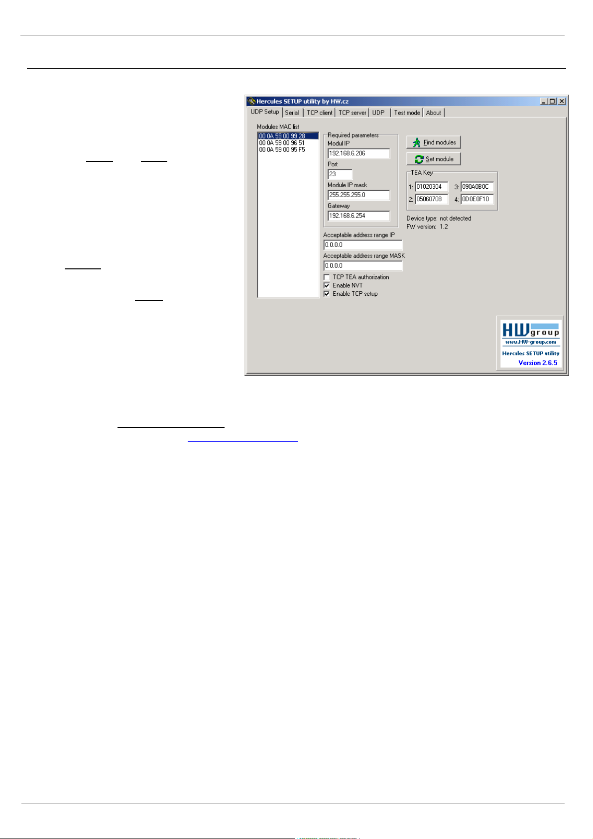
• Start the “HerculesSetup.exe” utility. It is available on the DVD (included in the “set” package)
or for free download at www.HW-group.com.
• In the “UDP Setup” tab, click “Find modules”. The MAC address of the device appears in the
left column. Click the MAC address and set the required parameters (at least the IP address,
mask and gateway).
• Make sure that “Enable TCP Setup” is checked. Click “Set module” to save the parameters to
the device.
• You have now configured the IP address and other networking parameters and you can work
with the device.
MAC address not visible in the list?
LINK LED did not light up or the device does not respond? Please double check the following.
- Does your Ethernet network support 10 Mbps devices?
- Are you using a correct TP cable (straight-wired TP Patch when connecting to an Ethernet
switch, crossover cable when connecting to a PC)?
- Check the DIP switch settings (all should be OFF).
- Check your power adapter, make sure the Power LED is on.
- Check the firewall settings at your PC.
Page 10

I/O Controller 2 Manual
HW group
www.HW-group.com
10/ 42
Configuring the device over WWW
In the UDP Setup tab, click the correct MAC address and press Open in the WEB browser.
You need to log in to access the configuration.
The default password is “admin” + “1234”
Default login:
▪ admin
▪ 1234
Page 11
I/O Controller 2 Manual
HW group
www.HW-group.com
11/ 42
Setting up the device using TCP Setup
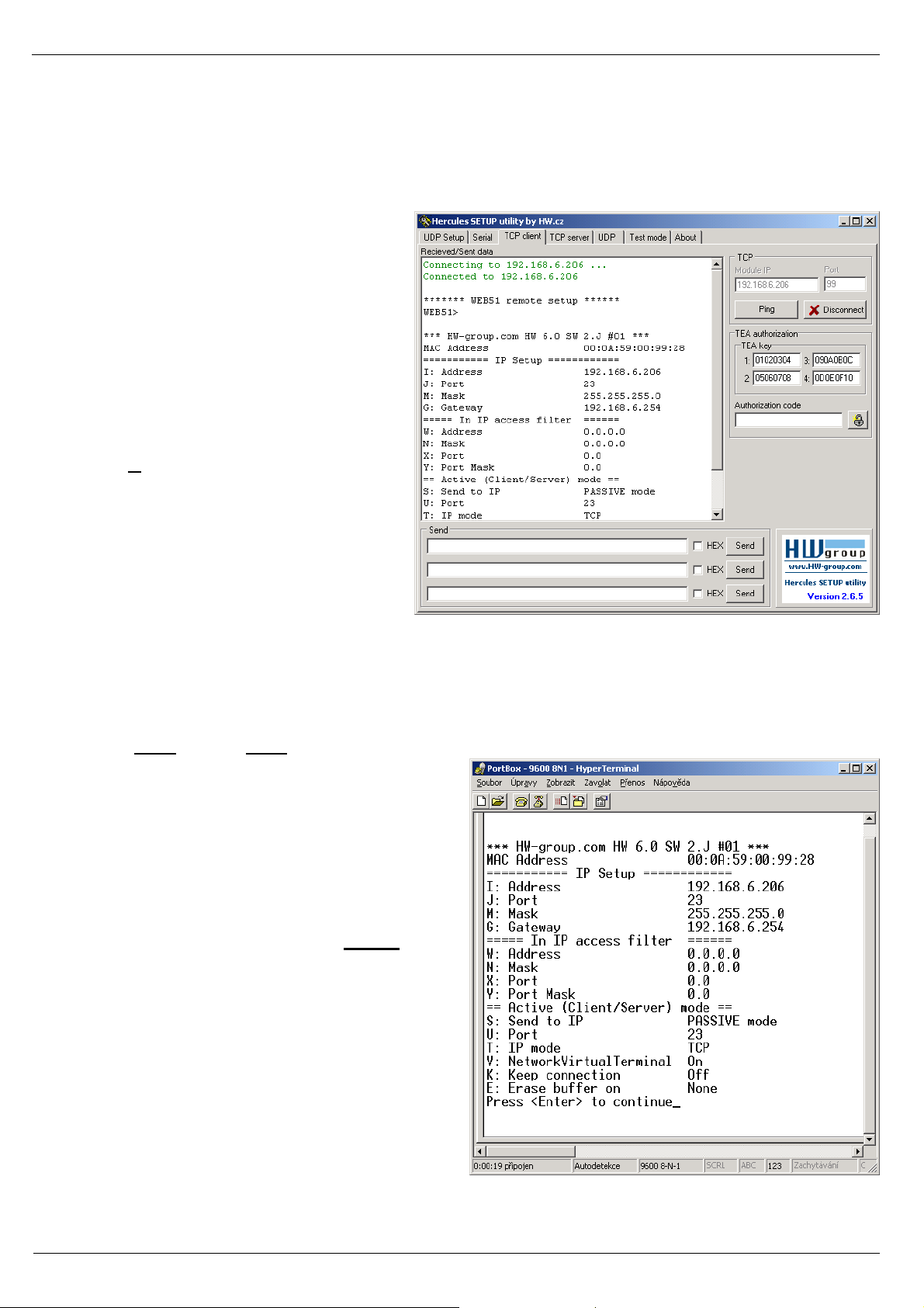
• Change to the “TCP Client” tab and enter the configured IP address. Set the TCP Port to 99.
• Click “Connect”. The listing on the left displays the “WEB51>” prompt. Click inside this pane
and press ENTER. The window displays the current configuration.
• To set a parameter, enter the
corresponding letter and the desired
value (for example “I192.168.6.8” to
set the device IP address). To show
the help for a command, enter the
command and a question mark, and
press ENTER – for example, “I?
<Enter>“. All the settings are
described in detail later in this
manual.
• After setting the parameters, use R
for Reboot and press “Disconnect”
to disconnect from the device. The
device restarts.
• Note: TCP Setup can be disabled
with the “Enable TCP setup” option.
When unchecked, the device
refuses connections to port 99.
Setting up the device using a RS-232 terminal
If you do not have Windows or our Hercules utility available, you can set up the device over RS-232
using any terminal.
• Set DIP1 = ON, DIP2 = OFF.
• Connect RS-232 (port 1) to a PC using the
supplied LapLink cable.
• Open your favorite terminal program (e.g.
Hyperterminal), choose the correct serial
port and configure it to 9600 8N1.
• Connect the power adapter to the
electrical outlet and to the device.
• If the power is OK, the green Power LED
lights up.
• If the serial cable and terminal program
are working, the text menu for configuring
the device appears.
Continue by following the steps as in the previous
case.
Page 12

I/O Controller 2 Manual
HW group
www.HW-group.com
12/ 42
Quick control of inputs and outputs
This chapter shows how to read a digital input and set a digital output to a desired value. We assume
that a test board supplied with device samples is used.
The following assumes that you know how to enter the setup mode (RS-232 Setup or TCP Setup at
port 99). The respective steps were described in the previous sections.
• Set DIP1 = OFF, DIP2 = OFF, connect the test board to the connector and turn on the
device.
• Change to the “UDP Setup” tab, find the devices, and make sure that the “Enable TCP setup”
and “Enable NVT” options in the lower left-hand portion next to the MAC list are checked for
the respective device . If not, check both options and save your settings to the device.
• Double-click the IP address in the “UDP Setup” tab and change to the “Test mode” tab. The
double-click action should transfer the IP address and port to the Test tab. If this does not
happen, enter the values manually.
• Click “Connect”. The listing at the
left-hand side displays Connecting,
followed by one or three NVT
commands in the received data. All
recognized commands are
displayed in blue.
The image shows the listing and the
configuration options of the
Hercules utility. To invoke the
menu, right-click inside the
receiving pane or the transmitting
pane.
• At this point, click “Read” in the
lower right-hand corner to read the
inputs (8 switches at the test
board). Input states are indicated by
the virtual LEDs D0 to D7,
respectively. States can be inverted
with the “LED polarity” option.
• The D0 – D7 checkboxes set the corresponding outputs. The first command sets all outputs to
defined states, subsequent commands set individual bits. Outputs can be again inverted using
the “Inversed” option.
The “Write together” option does not send commands immediately when an output is selected;
instead, outputs are set after clicking “Write”.
• When “Show I/O commands” is enabled, notice the I/O Controller control sequences in the
incoming and outgoing panels. This makes it easy to test the commands.
• Enter “FF F6” to the Send lines at the bottom, check HEX and click the corresponding Send
button to send this command. The receiving pane should show “<WEB51 HW 4.7 SW 2.J SN
00A608 #01>” or something similar. You have just sent your first NVT command requesting
“Are You There” identification, and the I/O Controller replied with its HW and SW version. The
SN number consists of the last three bytes of the MAC address.
• If the TCP connection is closed while working (red message “Connection refused by
remote host”), click “Connect” to reconnect. The module uses a rather short timeout (50 s)
for manual control.
Page 13

I/O Controller 2 Manual
HW group
www.HW-group.com
13/ 42
Setting up the device – Frequently Asked Questions
• Ethernet no longer works but LINK is lit.
Perhaps the device was left in the “RS-232 Setup” mode that is activated by setting DIP1 = ON? In
this mode, the Ethernet does not respond. Set DIP1 = OFF and restart the device by disconnecting
the power supply for at least 3 seconds.
• RS-485 communication does not work.
Make sure that termination resistors (120 – 470 Ohms) are present at the line or at the
connector.
• When using a RS485 converter, configure &I1 or &I2 and remember to turn on HALF DUPLEX
using &H1.
• I need to supply power to a RS-232 application.
If you don’t need to control data flow (HW handshake) but need to power a device connected to the
serial port (max. 5 – 10 mA), power your application from the RTS output (pin 7 at the RS-232
connector). The &R0 parameter (&R: RS485/RS422 control) in the setup connects approximately
+8 V to +12 V to this pin.
• Digital inputs and outputs cannot be controlled. RS-232 data work fine.
Most likely, “NVT” is disabled. Check this at the “UDP Setup” tab in the Hercules utility, in the TCP
Setup, or in the RS-232 Setup.
• 5-second timeout is too short to work with, is it possible to do something about it?
Yes, enable “Keep connection” in the Setup. I/O Controller then sends a command every 6
seconds that appears as “NVT: NOP” in the receiving pane, and the connection does not timeout.
Page 14

I/O Controller 2 Manual
HW group
www.HW-group.com
14/ 42
HW VSP – virtual serial port
Virtual serial port driver is a software tool that adds a virtual serial port (e.g. COM5) to the
operating system and redirects data from this port via the Ethernet network to another
hardware interface.
• The driver works in Windows XP, Vista, Windows 7, Windows 2003 Server, Windows 2008
Server, including 64-bit versions.
• If the device supports RFC 2217 (NVT), you can set the remote serial port parameters (speed,
parity, stop bits).
• The communication can be recorded to a LOG file for easier debugging.
• It is possible to create multiple virtual serial ports on a single computer (COM5, COM6,
COM7) by starting VSP.EXE from the command line with appropriate parameters.
Using HW VSP with I/O Controller
• Install HW VSP (“HW_VirtualSerialPort” directory on our CD). When installing, make sure to
check the option to install the second part. After installation, restart your PC.
• Make sure that NVT is enabled at the UDP Setup tab in the Hercules utility. If not, enable
NVT and save the settings.
• Start HW VSP and find the devices at the “UDPsetup” tab. Select the MAC address of the
device and click “Use this IP”. Change to the “Virtual SP” tab. The IP and Port should be
already set. This search via UDP Broadcast works only on a local network.
• Select a serial port to create from the COM1 to COM20 range and click “Create COM”. The
“LAN status” pane shows whether the device has been
found. If so, the virtual serial port is created.
• As soon as you start any application that opens the selected
virtual serial port (COM5 in this example), the HW VSP
driver establishes a connection with the I/O Controller,
configures the remote port (speed, parity, number of bits,
handshake) to match the virtual serial port being opened,
and starts transferring data.
Some applications have problems with serial port numbers
higher than COM4. You can always use Hyperterminal in
Windows, the Serial tab in the Hercules setup utility, or the
“Terminal.exe” utility originating from Slovenia and available
on the CD in the utils directory.
• Select the I/O Controller sub-tab in the “Binary I/O” tab. Here
you can set and read digital inputs and outputs without additional software.
Page 15

I/O Controller 2 Manual
HW group
www.HW-group.com
15/ 42
HW VSP settings
TEA Key pane
You can use TEA authentication to secure TCP/IP access. The
same TEA key must be set and enabled at both sides of the
communication.
NVT pane
Enables RFC2217 and detection of our remote ports. Remember
to activate NVT support on the remote device as well.
• NVT filter – Filters out NVT control characters from the data flow.
• NVT port setup – Configures the remote port parameters via control
commands to match the VSP in your PC. For example, if your
terminal program (e.g. Hyperterminal) changes the baudrate to 19200
Bd and this box is checked, the VSP driver sends a NVT command
(according to the RFC 2217 standard) to change the baudrate of the
remote TCP/IP serial port.
• Keep Connection – Keeps the TCP/IP connection open even after
50 seconds of inactivity.
Main HW VSP parameters
• Log enabled
The VSP driver logs the virtual serial port activity to “C:\serialport.log”.
• TCP server mode
Activates VSP as a TCP/IP server. The driver then behaves as a TCP Client/Server device –
the first side to receive any data switches to Client mode and establishes the connection.
The incoming TCP server port is configured at the main “Virtual SP” tab. We recommend
using port numbers higher than 1025.
• Create port on start VSP
Automatically creates virtual ports when the driver is started. To create virtual ports at
Windows startup, the “Start VSP on boot” box must be checked, too.
• Hide on startup
Hides VSP to to the system tray. The VSP icon is accessible near the clock.
• Don't create port if ping fail
Before creating the virtual serial port, tests if the device IP address responds.
• Connect to module if port is closed
If the virtual serial port is not in use by any application, checking this box can lead to losing
some received data from the remote device.
• Start VSP on boot
Inserts the VSP path to the RUN key
(HKEY_LOCAL_MACHINE\SOFTWARE\Microsoft\Windows\CurrentVersion\run) in the
Windows registry. VSP is then started every time Windows starts.
HW VSP – command line parameters
HW VSP can be started with specific parameters on the command line. In this way, it is possible to
create several virtual serial ports simultaneously on one computer. Detailed description of the
parameters can be found at our website: www.HW-group.com.
Example: CharonVirtualCom.exe -R -i192.168.6.21:23 -c5 -S0 -N1 -Nf -Np -H1
Page 16
I/O Controller 2 Manual
HW group
www.HW-group.com
16/ 42
I/O Controller configuration – Command description
The description of the settings combines WWW-based configuration and TCP/serial setup. Some
functions are only available in serial/TCP setup (TEA security settings, QUIT mode).
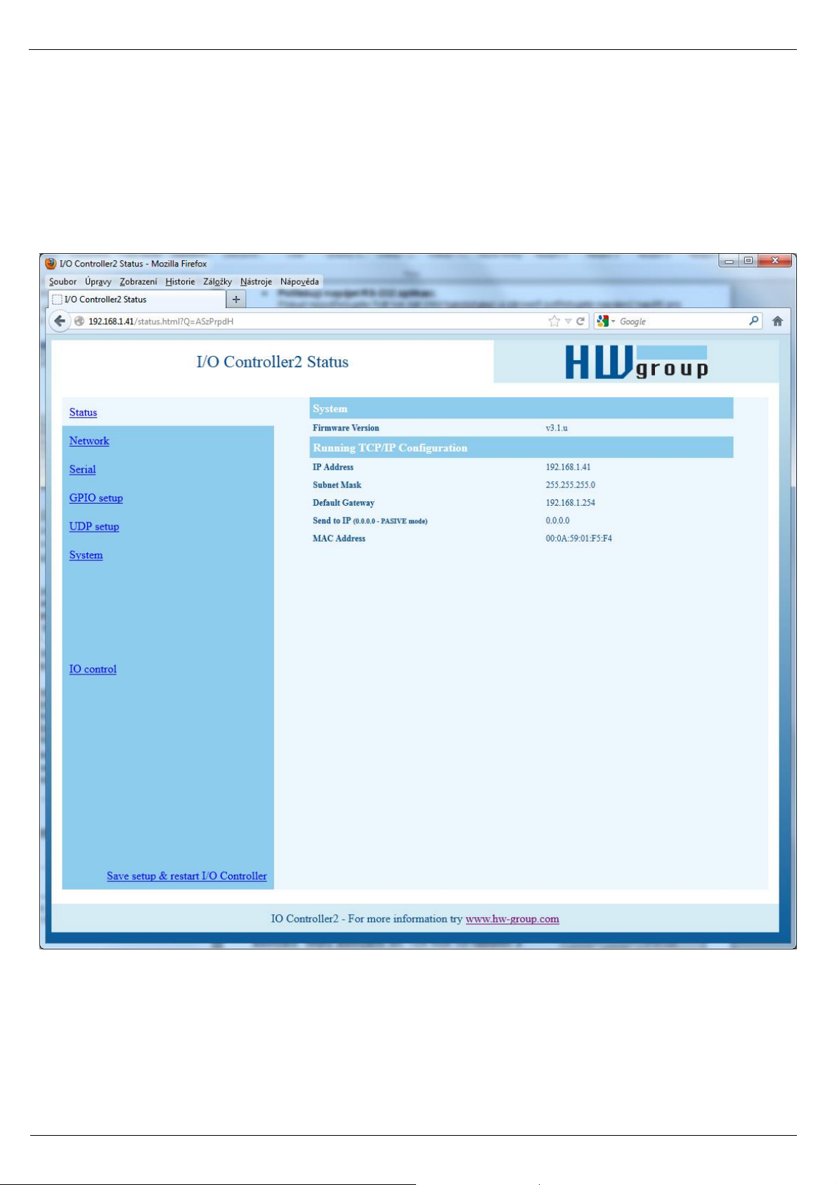
I/O Controller status page
Shows an overview of the basic device parameters.
Page 17
I/O Controller 2 Manual
HW group
www.HW-group.com
17/ 42
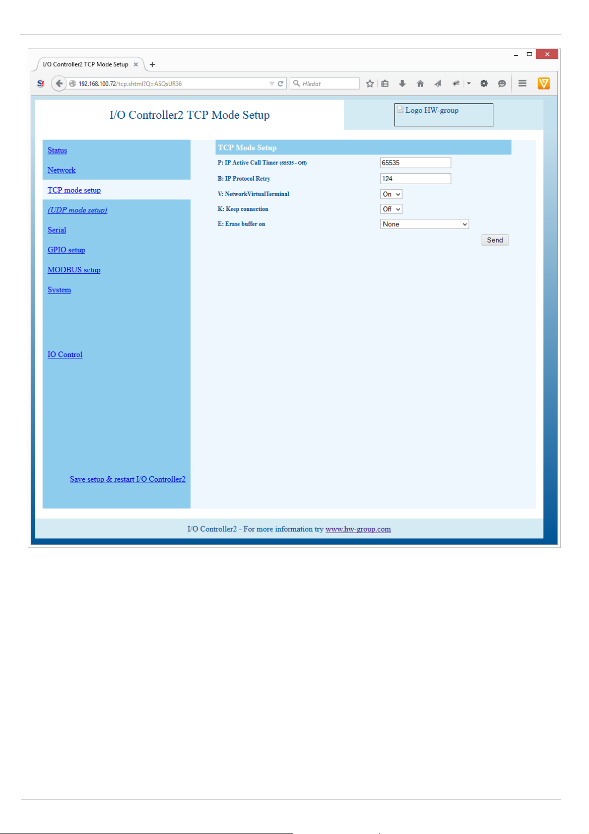
Network parameters + TCP Setup Mode
Page 18
I/O Controller 2 Manual
HW group
www.HW-group.com
18/ 42
Page 19

I/O Controller 2 Manual
HW group
www.HW-group.com
19/ 42
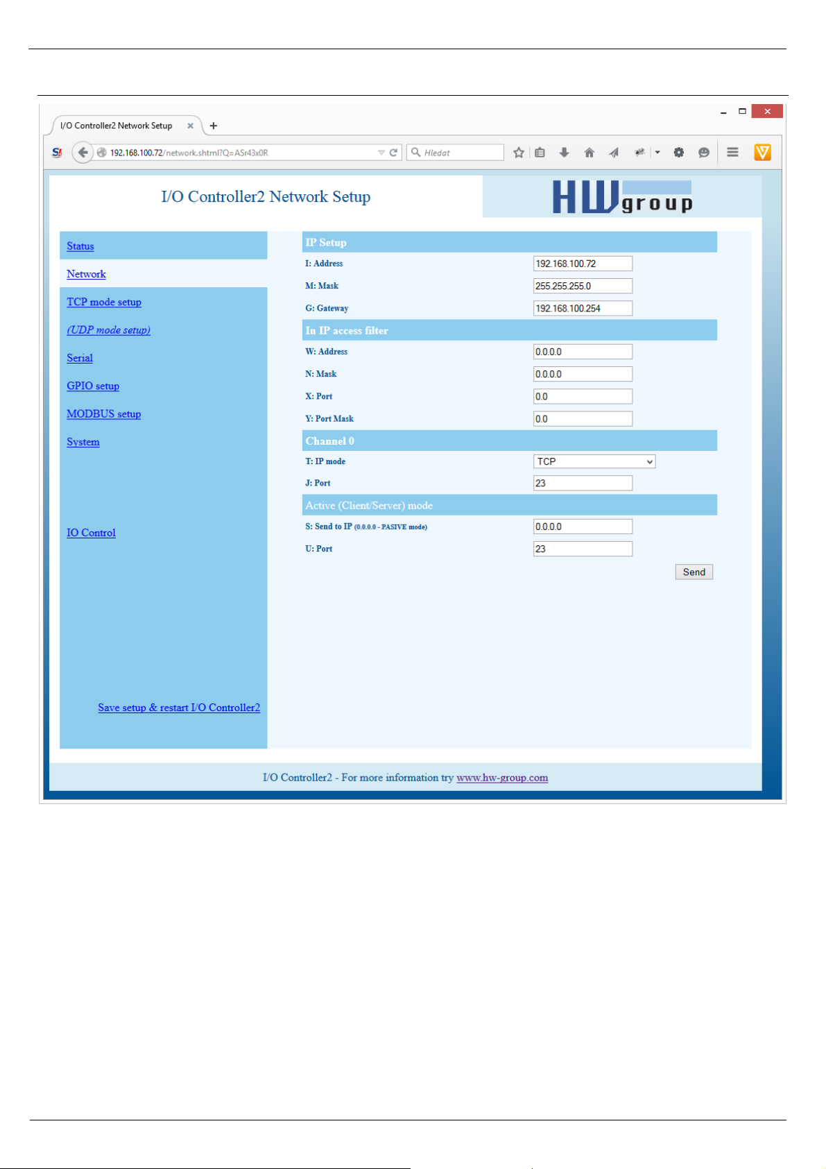
(IP attempting to access AND N ) = W
Access is granted if the above condition is
true. AND represents bitwise multiplication.
MAC Address 00:0A:59:00:95:6C
MAC address is a unique device address in the Ethernet network and it is always factory-preset. You
can find it on the label inside the device. Using this address, individual devices can be distinguished
for example in the UDP section of the setup program.
The address respects restoring of the default configuration with the “D0” command.
I: Address 192.168.6.15
Configures the IP address of the converter.
J: Port 23
Configures the converter's communication port –
from 1 to 65535.
Port 99 is reserved for TCP Setup, if supported by
the particular model and enabled in the setup.
M: Mask 255.255.255.0
IP network mask applicable in the local network.
Communication with all devices outside of the local
network (as determined by the IP address and
network mask) is directed through the gateway.
G: Gateway 192.168.6.254
Address of the Gateway that enables access to
external networks (outside of the IP range defined
by the converter's IP address and the mask).
====== In IP Setup ======
W: Address 0.0.0.0
IP address of a network or a computer that is allowed to communicate with the device. This value must be
the result of a bitwise AND of the remote IP address and the restriction mask (option N), otherwise the
device does not react.
N: Mask 0.0.0.0
This mask restricts addresses that are allowed to communicate with the device. Security can be
enhanced by setting a fixed address or a suitable restrictive mask that disallows communication with
unauthorized parties.
X: Port 0.0
Y: Port Mask 0.0
Restricts the range of TCP ports that can
communicate with the device.
MASK, IP address and Gateway functions:
An Ethernet device communicates:
• Within a local Ethernet network
No Gateway used or needed. However, IP
addresses of both sides must be within the
configured mask. For example, a mask of
255.255.255.0 means that the IP
addresses can only differ in the last byte.
• Outside of the local network – through
the Gateway, which itself must have an IP
address within the range delimited by the
mask.
In addition to this basic configuration, it is
possible to restrict the range of IP addresses
allowed to communicate with the converter in
“In IP Setup”. For debugging, we therefore
recommend to keep this parameter set to
0.0.0.0.
Page 20

I/O Controller 2 Manual
HW group
www.HW-group.com
20/ 42
Setting the connection length
Keeping a TCP socket open is
useful when small volumes of
data need to be transferred as
soon as they come in but HW
VSP is not used or a permanent
connection needs to be avoided.
For the duration specified by the B
option, the connection is kept
open and data are sent
immediately, without the delay for
establishing a TCP connection.
On the other hand, a long
timeout means a long period of
inaccessibility through other
sockets (disconnected cable,
TCP setup).
Port configuration in UDP mode
When UDP communication is
used, the remote address must
be specified here.
Otherwise, the communication
will be unidirectional. Data from
the I/O Controller are sent only
to the specified address.
====== Out IP Setup ======
S: Send to IP 192.168.0.252
U: Port 23
If the address in the S option is different from 0.0.0.0, the I/O
Controller works as a Client/Server in the TCP mode. This
means that if no TCP/IP connection is established and the
device either receives serial port data (even a single byte) or
the state of its digital inputs changes (in the range allowed by
the #T option), the device periodically tries to initiate a TCP
connection as a TCP Client. The device remains in the TCP
Server mode in between attempts.
In the UDP mode, the I/O controller sends data from the serial port to this address/port. Control of
digital inputs and outputs in the UDP mode is governed by #E and subsequent parameters.
Set S = 0.0.0.0 to switch the converter to the TCP Server mode.
B: IP Protocol Retry 124
Determines the TCP connection timeout if no communication
takes place. Predefined values are available through the
asterisk notation:
*1: 30 s (n = 35)
*2: 1 min. (n = 45)
*3: 2 min. (n = 63)
*4: 5 min. (n = 77)
*5: 10 min. (n = 101)
*6: 15 min. (n = 124)
*7: 30 min. (n = 144)
*8: 1 h (n = 179)
*9: 2 h (n = 249)
The timeout can be fine-tuned by specifying a value from 10 to
255 according to this formula:
n <16 .. n * 0.2 s
n < 32 .. (n- 15)* 0.8 s + 3.0 s
n < 64 .. (n- 31)* 3.2 s + 15.8 s
n <128 .. (n- 63)*12.8 s + 118.2 s
n <256 .. (n-127)*51.2 s + 937.4 s
Example: B42 => (42-31)*3.2+15.8 = 51s
P: IP Active Call Timer (65535 – Off)
Page 21

I/O Controller 2 Manual
HW group
www.HW-group.com
21/ 42
UDP/IP mode does NOT support
- NVT commands
- TEA authentication
Challenge-response protocols can
respond up to 40% faster.
T: IP mode TCP
Switches between the TCP and UDP protocols. UDP communication is faster but prone to lost packets or
out-of-order delivery; therefore, it is only suitable for communication on a local network segment in a
request-response mode, usually to convert RS485 communication.
The “broadcast Rcv” parameter allows receiving broadcasts.
0: TCP
1: UDP with broadcast Rcv Off
2: UDP with broadcast Rcv On
V: NetworkVirtualTerminal Off
Network Virtual Terminal enables interpretation of Telnet sequences, including certain RFC2217
extensions that enable on-the-fly changes of serial port parameters (speed, parity, etc.). NVT
description can be found at our website: >> “Support & download” >> “NVT (Network Virtual
Terminal) protocol description”.
When communicating with the serial port using telnet, e.g. with the TeraTerm program or the
Hercules utility, NVT should be enabled. If you don't want to use this option, set your client to “RAW”
communication mode.
0: Off (do not use telnet control codes, pass through to serial port)
1: On (accept telnet control codes)
Note: With NVT off, it is not possible to control the digital inputs and outputs, and the SETUP
does not even show the corresponding settings.
K: Keep connection Off
Keeps TCP connections alive to avoid automatic termination upon timeout specified by the B: IP
protocol retry time parameter. When enabled, the device sends a NVT NOP command
approximately every 5 seconds to check the connection state. If port sampling is enabled with the
#T: Trigger AND mask parameter, the device sends an I/O keep command (FF FA 2C 37 ..) instead
of a NOP (see #K, #L, #M, #N). NVT must be enabled for this parameter to take effect – when NVT is
off, I/O Controller repeats the last packet sent and the Keep function is dependent on the remote TCP
implementation.
0: no keep connection (preferred)
1: keep connection
E: Erase buffer on Open connection
Clears the internal device buffer when a connection is established or closed. This option is useful for
instance when your remote peripheral periodically sends some kind of “I'm alive” characters, you only
need to access it once in a while, and receiving all these characters from the buffer wastes time.
0: none
1: Close TCP/IP connection
2: Open TCP/IP connection
3: Open & Close TCP/IP connection
Page 22

I/O Controller 2 Manual
HW group
www.HW-group.com
22/ 42
Serial port parameters
====== Serial Setup ======
&B: Speed 9600
Sets the communication speed for the serial line. Any speed from 50 to 115,200 Bd can be set. To set
9600 Bd, enter “&B9600”. The resolution depends on the speed. Up to about 1000 Bd, 1 Bd steps can be
used. At 10 kBd, only 100 Bd steps are still usable.
&D: Data bits 8
Number of data bits in the serial communication.
7: 7 bits / 8: 8 bits – for instance, to set 8 data bits, enter “&D8”.
Page 23

I/O Controller 2 Manual
HW group
www.HW-group.com
23/ 42
&P: Parity NONE
Parity of the serial asynchronous communication.
For example, to configure communication without parity, enter “&PN”.
N: none / O: odd / E: even / M: mark / S: space
&V: Variable Parity Parity Off
Supplemental function for 9-bit protocols. Only the difference from the pre-set parity bit value is
transmitted. For correct operation, a parity needs to be set (usually Mark/Space). A double character
(0xFE followed by “P”) is used to transfer the difference from the pre-set parity. In this mode, the
0xFE character is a prefix; if it appears within the data stream, it needs to be doubled. This option is
recommended for the box-2-box mode (two converters connected back-to-back) and 9-bit protocols.
Off: incorrect parity bit ignored
On: incorrect parity bit transmitted to the other device
For instance, to set up 9-bit communication with a majority of data having “space parity”, enter:
“&PS;&V1” (space parity + variable parity on).
&S: Stop bits 2
Number of stop bits for the serial communication. As a rule, there should be at least 9 bits and at
most 10 bits in total, excluding the start bit. For instance, the 7N1 setting (7+0+1 bits) is corrected by
the setup to 7N2. Similarly, 8E2 (8+1+2 bits) is corrected to 8E1.
&C: Flow Control NONE
Serial data flow control. If you use data flow control and the input buffer is full, handshake will signal over
the serial port that the I/O Controller can no longer accept data.
1: none – No control, for RTS function see &R
2: RTS/CTS – RTS/CTS control pins
3: Xon/Xoff – Software flow control
4: Xon/Xoff HeartBeat – SW flow control with periodic Xon transmission (heartbeat)
&R: RTS Output Continuously asserted [~ +8V]
Defines the idle level of the RTS output pin. Important for devices powered from the RTS pin.
0: RTS = continuously asserted [~ +8V]
1: RTS = unasserted [~ -8V]
2: RTS = asserted while connected
&A: DTR Output
Defines the idle level of the DTR output pin. Important for devices powered from the DTR pin.
0: DTR = continuously asserted [~ +8V]
1: DTR = unasserted [~ -8V]
2: DTR = asserted while connected
Page 24

I/O Controller 2 Manual
HW group
www.HW-group.com
24/ 42
&I: RS485/RS422 control Off
For RTS or downstream RS485 converters that use RTS to toggle transmission/reception. For the built-in
RS-485 driver, the “HW echo” option applies, meaning that the device reads back the data sent to the RS-
485 line and generates an echo from the actual RS-485 bus.
0: Off
2: TxRTS HW echo ON (recommended for RS-485 debug only!)
3: TxRTS HW echo OFF (RS-485)
Note: For most RS-485 applications, set &R3TxRTS HW echo OFF.
&T: Serial Line Timeout 0 – Off
If no data are received from the serial line for the specified time, characters received so far are
packed into an Ethernet packet and sent off.
The timeout is specified as the number of characters, and displayed as the number of chars as well
as the time based on the current serial communication speed. If the speed changes, the time is
recalculated but the number of characters defining the timeout stays the same (10 characters means
about 11 ms at 9600 Bd, or 5.7 ms at 19200 Bd).
&G: Char. Transmit Delay 0 – Off
When controlling devices with a small RS232 buffer, it is sometimes advantageous to keep a
relatively high baud rate but insert delays between individual characters. The delay is specified in
milliseconds and defines the time between the starts of individual characters. Therefore, delays
under 2 ms have no effect at 2400 Bd because individual characters are 2.4 ms apart.
&H: Tx Control Tx FULL duplex
When HALF duplex is activated, the converter expects unidirectional communication over the serial
line (RS485) and never starts to transmit data while receiving.
&Q: EOT Trigger character 26
Packet termination character. The default is 26 (ctrl-Z in ASCII). In common operating systems, ctrlZ
is the EOF (End Of File) character. When this character is received from the serial line, the device
does not wait for the “&T” timeout and immediately sends everything as a packet over LAN.
%S: TCP/IP setup On
Enables or disables remote configuration through the TCP Setup at port 99. This command only
works in the RS-232 Setup mode.
0: TCP Setup disabled
1: TCP Setup enabled (TCP server at port 99)
0: FULL duplex (RS-232)
1: HALF duplex (RS-485)
Page 25

I/O Controller 2 Manual
HW group
www.HW-group.com
25/ 42
Configuring the control of inputs and outputs
TCP/IP mode needs to be configured and NVT (Network virtual terminal) enabled in order to work
with the digital inputs and outputs. Otherwise, the commands are not even displayed.
Digital inputs and outputs are controlled over the Network Virtual Terminal. This means that the I/O
control commands are embedded into the TCP/IP data stream, along the serial port data. However,
these commands only appear in the Ethernet communication, they never pass through to the serial
port.
In recent firmware versions, digital inputs and outputs can be controlled from the serial port or over
an UDP connection (see #E and #V).
NVT commands are always prefixed with a control character and have a predefined binary format.
A detailed description of the NVT protocol with examples of commands is available at our website (in
the “Support & Download” section).
Note: Remember to set the desired initial value of outputs after reset.
Page 26

I/O Controller 2 Manual
HW group
www.HW-group.com
26/ 42
======= I/O Control Setup =======
#T: Trigger AND mask 240
Defines inputs whose changes are automatically transmitted to the remote side (IP address
S=X.X.X.X and port U) and synchronized with its outputs, if they change.
Only those inputs for which the corresponding bits of #T are set to 1 are transmitted.
Examples:
• #T = 0 (0x00) – I/O Controller does not react to any changes at digital inputs I0 through I8.
• #T = 240 (0xF0) – I/O Controller only reacts to changes at digital inputs I7, I6, I5, I4. Changes
at inputs I3 to I0 are ignored. However, their changed values are always transmitted together
with any reaction to a change at I7..I4.
• #T = 255 (0xFF) – I/O Controller reacts to any change at any digital input I0 through I8.
Transmission means that whenever the I/O Controller is in the Client/Server mode (“Active mode”), it
reacts to changes at its inputs just as it reacts to incoming data from the serial port = if the connection
is closed, the I/O Controller establishes a connection with the specified remote side and sends the
appropriate NVT command to set the remote outputs.
If the TCP Server mode (“Passive mode”) is used and the connection is closed, nothing happens. If
the connection is open, data are send through the open connection.
Note: Even if the input states are not transmitted to the remote side, they can still be read
using the standard NVT commands for reading inputs.
I/O Controller distinguishes three types of synchronization when using two devices back-to-back.
Their parameters are usually configured in a similar way:
• Power Up init – (#B, #C, #D parameters) – After reset, I/O Controller sets the output to the
value specified in #A and attempts to contact the remote IP defined with S=x.x.x.x. When
successful, it requests the state of the remote device's inputs and sets its own inputs
according to the following formula.
• Data change – (#X, #Y, #Z, #W parameters) – Upon every change at the inputs (as restricted
with #T), I/O Controller informs the remote device. The remote device receives the value and
uses the second formula to set its outputs.
• Keep I/O – (#K, #L, #M, #N parameters) – I/O Controller periodically sends the state of its
inputs to the remote side.
Data synchronization after RESET (Power Up init):
The device keeps trying to establish the connection for approximately 120 seconds after powering up.
If it does not succeed, the #A: Power Up INIT value remains at the output.
OUTPUT = ((retrieved remote data AND #B) OR #C) XOR #D
Page 27

I/O Controller 2 Manual
HW group
www.HW-group.com
27/ 42
Bitwise OR
0 (0x00) OR 0 (0x00) = 0 (0x00)
255 (0xFF) OR 0 (0x00) = 255 (0xFF)
255 (0x0F) OR 3 (0x03) = 255 (0xFF)
240 (0xF0) OR 8 (0x08) = 248 (0xF8)
#A: Power Up INIT 0
A decimal value from 0 to 255 that is written to the output register after device reset (or power
failure), before the I/O Controller attempts to establish a connection with the remote unit and
synchronize their digital inputs and outputs.
#B: Power Up AND mask 255
Binary mask of values from the remote side that affect the outputs when initializing for the first time
(after reset or power up).
#C: Power Up OR mask 0
Range of digital output values that can be
influenced by the states of inputs retrieved from the
remote side after RESET.
#D: Power Up XOR mask 0
The binary XOR function is suitable inverting individual output bits. This is used, for example, when a
button closes against GND but the corresponding relay needs to switch against +PWR (logic LOW at
the input needs to be inverted to logic HIGH at the output).
Examples:
• #D = 0 (0x00) – Values are transferred without changes. Logic HIGH at an input results in a
logic HIGH at the respective output.
• #D = 1 (0x01) – The D0 output bit is inverted with respect to the D0 input bit. Values at D1
through D7 are transferred without changes. Logic HIGH at an input results in a logic HIGH at
the respective output.
• #D = 255 (0xFF) – All output bits are inverted with respect to the respective input bits.
Page 28

I/O Controller 2 Manual
HW group
www.HW-group.com
28/ 42
Bitwise AND
0 (0x00) AND 0 (0x00) = 0 (0x00)
255 (0xFF) AND 0 (0x00) = 0 (0x00)
255 (0x0F) AND 3 (0x03) = 3 (0x03)
240 (0xF0) AND 16 (0x0F) = 0 (0x00)
Bitwise XOR
0 (0x00) XOR 0 (0x00) = 0 (0x00)
255 (0xFF) XOR 0 (0x00) = 255 (0x00)
255 (0x0F) XOR 3 (0x03) = 252 (0xFC)
0 (0x00) XOR 255 (0xFF) = 255 (0xFF)
Data synchronization in normal operation:
- PrevOut = previous output state
- RxData = received remote data
Note: The previous formula is only used when two I/O Controllers are connected to each
other back-to-back. Inputs at one device are automatically mirrored at the outputs of
the other device. This is called the Box-2-Box mode.
Standard NVT commands can be used to access all the 8 output bits either directly,
without respect to the #B to #Z parameters, or using the defined masks.
However, in the common Box-2-Box mode, it is not possible to access the output
states from a PC because the I/O Controller supports only one TCP connection at a
time. As long as a TCP connection to the other I/O Controller is established, the I/O
Controller cannot be accessed from a PC.
#X: KEEP mask 0
Defines the outputs that will keep their previous values (using bitwise AND).
#Y: AND mask 255
Using bitwise AND, defines the inputs whose states
are transmitted from the remote side to the outputs
of the I/O Controller.
Note: Be careful when controlling the outputs over NVT and using the Box-2-Box mode at the
same time. #X and #Y can define which bits can be set only over NVT and which bits will
be synchronized with the remote inputs.
Example: #Y= 0x00, #X=0xFF – The output is not affected by the remote side at all, all
output bits can be controlled over NVT.
#Z: OR mask 0
Defines the output bits that will be affected by automatic synchronization – see #C.
#W: XOR mask 0
The bitwise XOR function is useful for inverting
individual output bits with respect to the respective
remote inputs – see #D.
OUTPUT = ((PrevOut AND #X) OR (RxData AND #Y) OR #Z) XOR #W
Page 29

I/O Controller 2 Manual
HW group
www.HW-group.com
29/ 42
Periodic data synchronization in normal operation:
- PrevOut = previous output state
- RxData = received remote data
Keep I/O – (#K, #L, #M, #N parameters) – I/O Controller periodically sends the states of its
inputs to the remote side.
#K: KEEP mask 255
#L: AND mask 0
#M: OR mask 0
#N: XOR mask 0
#K#L#M#N commands correspond to #X#Y#Z#W and define the behavior when two I/O Controllers
are connected back-to-back and configured to periodically transmit port states. #X#Y#Z#W
commands define the behavior of the two I/O Controllers whenever the port states change (more
precisely, whenever the bits determined by #T change).
#H: I/O HeartBeat Off
Configures I/O Controller behavior when periodically transmitting input states. It is related to the
K: Keep connection parameter.
• K0 disables periodic state transmission, #K#L#M#N#H have no effect and are inaccessible in
the menu.
• K1;H0 enables periodic state transmission only when nothing else is sent (e.g. data from the
serial port).
• K1;H1 enables periodic state transmission approximately every 5 seconds regardless of the
serial port communication.
Setup examples
Using the described parameters, each bit can be independently configured either to keep a fixed
value, to synchronize itself with changes at an input, or to invert its state with respect to the state of
an input. Study the following examples:
Output = (X.n =0 Y.n =0 Z.n =0) – output at logic LOW, configurable only with NVT commands
Output = (Z.n =1) – output at logic HIGH, configurable only with NVT commands
Output = (X.n=0 Y.n=1 Z.n=0 W.n=0) – output is an exact copy of the remote input
Output = (X.n=0 Y.n=1 Z.n=0 W.n=1) – output is an inverted copy of the remote input
Note: In normal operation, the inputs are sampled every millisecond and a change is
registered whenever the input value differs from the last transmitted value in two
consecutive samples (= the change lasts at least 1.2 to 2.0 ms).
Output = ((PrevOut AND #K) OR (RxData AND #L) OR #M) XOR #N
Page 30

I/O Controller 2 Manual
HW group
www.HW-group.com
30/ 42
I/O TCP/IP Connection
Umožní nastavit výstupy při ztrátě či obnovení TCP spojení do požadovaného stavu
#1 AND mask for Opened TCP Connection
#2 OR mask for Opened TCP Connection
#3 XOR mask for Opened TCP Connection
#4 AND mask for Closed TCP Connection
#5 OR mask for Closed TCP Connection
#6 XOR mask for Closed TCP Connection
Masky se počítají identicky jako v případě parametrů GPIO Mask, tedy:
#Y/#L: AND mask
#Z/#M: OR mask
#W/#N: XOR mask
Transmitting input states upon an edge
I/O Controllers can transmit current input states to corresponding outputs at a specified remote
device. The inputs to mirror are defined by the edge mask.
------- I/O edge mask ------#R: Rise edge mask 255
Defines the inputs that will be monitored for rising edges. A rising edge triggers the transmission of
information about an input state change (“closed” state is transferred):
255=all inputs, 00=no inputs.
#F: Fall edge mask 255
Defines the inputs that will be monitored for falling edges. A falling edge triggers the transmission of
information about an input state change (“open” state is transferred):
255=all inputs, 00=no inputs.
Configuration of I/O control
I/O lines can be controlled over:
• WEB
• TCP Telnet (NVT commands)
• RS-232 (NVT commands sent to the serial port – #V)
• UDP (NVT commands via UDP to the specified port – #U)
• Modbus/TCP
Page 31
I/O Controller 2 Manual
HW group
www.HW-group.com
31/ 42
------- I/O control ------#E: GPIO control from UDP Off
#J: Port 24
When enabled, commands to change output states can be sent to the I/O Controller over UDP as
well as over TCP.
#J defines the UDP port where the I/O commands need to be sent.
#S: Send to IP 192.168.0.252
#U: Port 4024
When the UDP GPIO Control mode is enabled, I/O Controller sends the state changes to the
specified address and port.
#V: GPIO control from COM Off
When enabled, I/O Controller inputs and outputs can be controlled over the serial line. Commands
are similar to NVT commands – 0xFE prefix followed by a NVT command. For example, 0xFE 0x33
xx sets the output to xx. The prefix is the same as for the &V command.
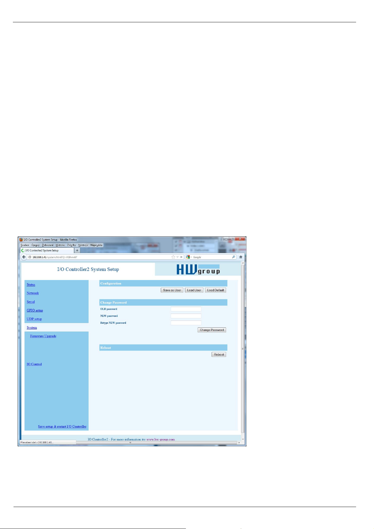
System
========= Other =========
D: Load/Save Settings from/to Flash
Saves the current settings to memory, or restores saved settings.
Page 32

I/O Controller 2 Manual
HW group
www.HW-group.com
32/ 42
0: Restores settings from slot 1
1: Restores settings from slot 2
2: Stores current settings to slot 1
3: Stores current settings to slot 2
R: Reboot
Software restart. Necessary e.g. when the IP address is changed. Recommended after changing
parameters in TCP Setup.
Change Password
Applies only to WWW access. The default password is 1234.
Page 33
I/O Controller 2 Manual
HW group
www.HW-group.com
33/ 42
UDP/IP mode settings
When “T: IP mode UDP” is chosen, the device will communicate with the remote party using UDP
packets. Also, the following menu appears in the Setup.
Page 34

I/O Controller 2 Manual
HW group
www.HW-group.com
34/ 42
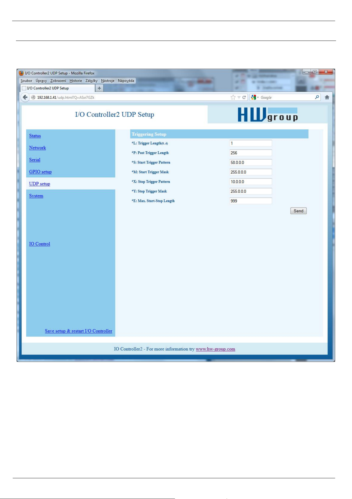
Configuration example
To send all data from the serial
line to the remote device, use
this configuration:
*L: Trigger Length 0
*P: Post Trigger Length 0
*S: Start Trigger Pattern 0.0.0.0
*M: Start Trigger Mask 0.0.0.0
*X: Stop Trigger Pattern 255.0.0.0
*Y: Stop Trigger Mask 255.0.0.0
*E: Max. Start-Stop Length 200
(4B input data AND *M) = *S
(4B input data AND *Y )= *X
==== Trigerring Setup =====
*L: Trigger Length 1
Number of bytes for the packet start and packet end triggering condition. Allowed values are 0 to
4. If the lengths of your start and end conditions differ, use the trigger condition mask and
remember to include the masked characters in the length of the triggering condition, even though
they contain actual frame data.
*P: Post Trigger Length 0
In some protocols, the packet end condition is followed e.g. by a checksum. This condition defines
the number of characters that make up a packet after the packet termination condition. If the start
and stop trigger conditions are equal, this value specifies the packet length without the leading 0 to
4 bytes of the start trigger.
*S: Start Trigger Pattern 58.0.0.0
Start trigger condition for packet transmission. Four bytes
are set; however, only the number of bytes specified in “L: Trigger Length” is considered.
*M: Start Trigger Mask 255.0.0.0
Mask of the start trigger condition. Masking works similarly to the Ethernet netmasks using a bitwise
AND. Value of 255 means that the tested character must be equal to the character specified in “V: Start
Trigger Pattern”. For example, to start the transfer with any ASCII control character (0..31d), use 0.0.0.0
for the trigger pattern, 224.0.0.0 for the mask and 1 for the length. If you set the character to 0 and the
mask to 0, the trigger matches any character.
*X: Stop Trigger Pattern 10.0.0.0
Sets the stop trigger condition for sending data to the Ethernet.
*Y: Stop Trigger Mask 255.0.0.0
Mask of the stop packet trigger condition for serial line data. For
example, the settings displayed here are intended for
transferring data in the IntelHEX format over RS485. The start
trigger is a colon and the transfer is terminated after receiving
the <LF> (0Ah = 10d) control character.
*E: Max. Start-Stop Length 999
Maximum number of characters that the device sends after the
START trigger, unless the STOP trigger is encountered sooner.
After transmission, another START trigger is expected.
Essentially, this is a “timeout” specified as the number of
characters.
Page 35

I/O Controller 2 Manual
HW group
www.HW-group.com
35/ 42
Parameters unavailable in the WWW interface
Security
===== Security Setup ======
%A: TCP autorisation Off
Activates TEA authentication (one-time exchange and
password verification to allow the TCP connection to be established) – requested from the remote
side after the connection is established.
%K: TEA key 0:01:02:03:04 1:05:06:07:08 2:09:0A:0B:0C 3:0D:0E:0F:10
Use “%K” to set the TEA key. Set 16 bytes as four quadruples of colon-separated hex values. The
first character identifies the quadruple (0th to 3rd). So, to set the last 4 bytes to the displayed value,
use “%K3:0D:0E:0F:10”. The key is used to verify one-time passwords (OTP) when authenticating
the remote side.
Other device parameters
Q: Quiet (Batch) mode
Quiet mode is useful when the configuration parameters need to be handled automatically, with a
script. Quiet mode is enabled with “Q1”. After pressing Enter, the device responds with a list of
parameters in the following format:
WEB51=2.L=00:0A:59:00:A6:08;I192.168.1.24;J23;M255.255.255.0;G192.168.1.1;W0.0.0.0;N0.0
.0.0;X0.0;Y0.0;S192.168.6.51;U4023;T0;V0;K1;A250;&B9600;&D8;&P1;&S1;&C1;&R0;&T0;&G0;&H0
;%A0;%K01:02:03:04:05:06:07:08:09:0A:0B:0C:0D:0E:0F:10;%S1;#T3;#A3;#B192;#C3;#D0;#X0;#Y
0;#Z3;#W0;*L1;*P0;*S58.0.0.0;*M255.0.0.0;*X10.0.0.0;*Y255.0.0.0;*E999
0: TEA authentication Off
1: TEA authentication On
Page 36

I/O Controller 2 Manual
HW group
www.HW-group.com
36/ 42
What's new in the WEB interface
IO Control – Read inputs and control outputs
Outputs can be controlled either by entering a decimal value 0–255 corresponding to the output
states, or by toggling the switches at the WWW page.
Page 37

I/O Controller 2 Manual
HW group
www.HW-group.com
37/ 42
Firmware upgrade
Upgrades the current device firmware. This operation may change some settings.
Page 38

I/O Controller 2 Manual
HW group
www.HW-group.com
38/ 42
Default settings
*** HW-group.com HW 6.0 SW 3.1.u #01 ***
*** PortBox I/O ***
MAC Address 00:0A:59:01:F5:F4
=========== IP Setup ============
I: Address 192.168.1.41
J: Port 23
M: Mask 255.255.255.0
G: Gateway 192.168.1.254
===== In IP access filter ======
W: Address 0.0.0.0
N: Mask 0.0.0.0
X: Port 0.0
Y: Port Mask 0.0
== Active (Client/Server) mode ==
S: Send to IP PASSIVE mode
U: Port 23
B: IP Protocol Retry 124
T: IP mode TCP
V: NetworkVirtualTerminal On
K: Keep connection Off
E: Erase buffer on None
Press <Enter> to continue
========= Serial Setup ==========
&B: Speed 9600
&D: Data bits 8
&P: Parity None
&V: Variable Parity Off
&S: Stop bits 1
&C: Flow Control None
&R: RTS Output continuously asserted [~ +8V]
&A: DTR Output unasserted [~ -8V]
&T: Serial Line Timeout 0 - Off
&G: Char. Transmit Delay 0 - Off
&H: Tx Control Tx FULL duplex
&I: RS485/RS422 control Off
======== Security Setup =========
%A: TCP autorisation Off
%K: TEA key 0:01:02:03:04 1:05:06:07:08 2:09:0A:0B:0C 3:0D:0E:0F:10
%S: TCP/IP setup On
Press <Enter> to continue
======= I/O Control Setup =======
#T: Trigger AND mask 255
#A: Power Up INIT 0
#B: Power Up AND mask 255
#C: Power Up OR mask 0
#D: Power Up XOR mask 0
#X: KEEP mask 0
#Y: AND mask 255
#Z: OR mask 0
#W: XOR mask 0
------- I/O edge mask ------#R: Rise edge mask 0
#F: Fall edge mask 0
------- I/O control ------#E: GPIO control from UDP Off
-------- Active COM mode -------#V: GPIO control from COM Off
Press <Enter> to continue
============ Other ============
D: Load/Save Settings from/to Flash
R: Reboot
WEB51>
Page 39
I/O Controller 2 Manual
HW group
www.HW-group.com
39/ 42
Practical configuration examples
The following examples show the configuration of essential parameters for typical applications.
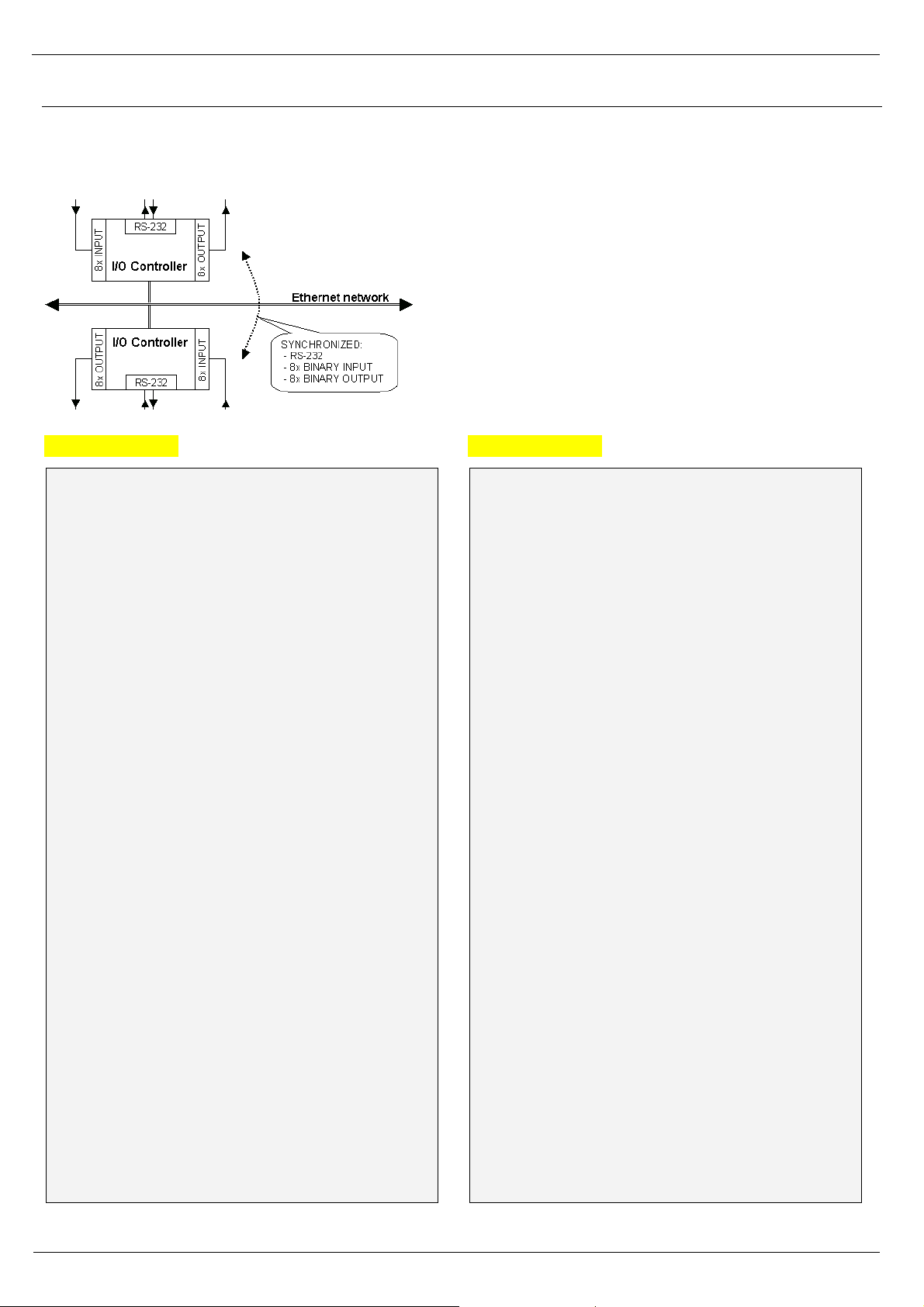
2x I/O Controller connected to each other (Box-2-Box)
Virtual extension of the serial port + 8 inputs and
8 outputs over TCP/IP.
The serial port is set to 19,200 Bd, 8N1, SW
handshake, states of digital inputs are mirrored at the
corresponding outputs.
The TCP connection automatically closes after 50
seconds, and opens again upon a change at an input
or upon receiving any data from the serial port.
I/O Controller 1
*** HW-group.com HW 4.7 SW 2.L #01 ***
*** I/O Controller ***
MAC Address 00:0A:59:00:00:00
=========== IP Setup ============
I: Address 192.168.1.1
J: Port 4023
M: Mask 255.255.255.0
G: Gateway 192.168.1.254
===== In IP access filter ======
W: Address 0.0.0.0
N: Mask 0.0.0.0
X: Port 0.0
Y: Port Mask 0.0
== Active (Client/Server) mode ==
S: Send to IP 192.168.1.2
U: Port 4023
T: IP mode TCP
V: NetworkVirtualTerminal On
K: Keep connection Off
E: Erase buffer on None
========= Serial Setup ==========
&B: Speed 19200
&D: Data bits 8
&P: Parity NONE
&V: Variable Parity Off
&S: Stop bits 1
&C: Flow Control Xon/Xoff
&R: RS485/RS422 control RTS = On [+8V]
&T: Serial Line Timeout 0 - Off
&G: Char. Transmit Delay 0 - Off
&H: Tx Control Tx FULL duplex
======== Security Setup =========
%A: TCP autorisation Off
%K: TEA key 0:01:02:03:04 1:05:06:07:08
2:09:0A:0B:0C 3:0D:0E:0F:10
%S: TCP/IP setup On
======= I/O Control Setup =======
#T: Trigger AND mask 255
#A: Power Up INIT 189
#B: Power Up AND mask 255
#C: Power Up OR mask 0
#D: Power Up XOR mask 0
#X: KEEP mask 0
#Y: AND mask 255
#Z: OR mask 0
#W: XOR mask 0
============ Other ============
D: Load/Save Settings from/to Flash
R: Reboot
WEB51>
I/O Controller 2
*** HW-group.com HW 4.7 SW 2.L #01 ***
*** I/O Controller ***
MAC Address 00:0A:59:00:00:00
=========== IP Setup ============
I: Address 192.168.1.2
J: Port 4023
M: Mask 255.255.255.0
G: Gateway 192.168.1.254
===== In IP access filter ======
W: Address 0.0.0.0
N: Mask 0.0.0.0
X: Port 0.0
Y: Port Mask 0.0
== Active (Client/Server) mode ==
S: Send to IP 192.168.1.1
U: Port 4023
T: IP mode TCP
V: NetworkVirtualTerminal On
K: Keep connection Off
E: Erase buffer on None
========= Serial Setup ==========
&B: Speed 19200
&D: Data bits 8
&P: Parity NONE
&V: Variable Parity Off
&S: Stop bits 1
&C: Flow Control Xon/Xoff
&R: RS485/RS422 control RTS = On [+8V]
&T: Serial Line Timeout 0 - Off
&G: Char. Transmit Delay 0 - Off
&H: Tx Control Tx FULL duplex
======== Security Setup =========
%A: TCP autorisation Off
%K: TEA key 0:01:02:03:04 1:05:06:07:08
2:09:0A:0B:0C 3:0D:0E:0F:10
%S: TCP/IP setup On
======= I/O Control Setup =======
#T: Trigger AND mask 255
#A: Power Up INIT 189
#B: Power Up AND mask 255
#C: Power Up OR mask 0
#D: Power Up XOR mask 0
#X: KEEP mask 0
#Y: AND mask 255
#Z: OR mask 0
#W: XOR mask 0
============ Other ============
D: Load/Save Settings from/to Flash
R: Reboot
WEB51>
Page 40

I/O Controller 2 Manual
HW group
www.HW-group.com
40/ 42
• To permit communication with only one address, set N:255.255.255.255 and W:IP address of
the remote device.
• To use 9-bit communication, enable &V1 = &V: Variable Parity On at both devices.
• To enhance security, disable TCP Setup at port 99 with %S0 = %S: TCP/IP setup Off at both
devices.
If security is an essential requirement and the device should only communicate within the local
network, use the following settings. In this case, only communication within the LAN segment is
allowed (0 to 255 at the end of the IP address).
I: Address 192.168.1.1
M: Mask 255.255.255.0
===== In IP access filter ======
W: Address 192.168.1.0
N: Mask 255.255.255.0
S: Send to IP 192.168.1.2
I: Address 192.168.1.2
M: Mask 255.255.255.0
===== In IP access filter ======
W: Address 192.168.1.0
N: Mask 255.255.255.0
S: Send to IP 192.168.1.1
Page 41
I/O Controller 2 Manual
HW group
www.HW-group.com
41/ 42
Controlling inputs and outputs via NVT
The following is a short overview of controlling the I/O Controller via the M2M NVT protocol. It is an
extract from the detailed description of NVT that is available at our website:
http://www.hw-group.com/support/nvt/index_en.html
What is NVT and RFC2217
NVT is a method of embedding control commands into a binary data stream. NVT (Network Virtual
Terminal) is also used by the Telnet protocol to transfer commands. In this way, Telnet transfers
control sequences such as CTRL-Pause, cursor positioning on the screen, changing terminal type,
and so on.
For remote control of serial ports, Cisco has defined RFC2217 that defines commands for changing
the serial port speed, querying the states of digital I/O signals, etc. Our devices implement most of
these commands. For a list, see the online description of NVT at the above-mentioned website.
We extended the standard RFC2217 commands to
include several GPIO (General Purpose Input Output)
functions listed below. These functions can control the
digital input and output pins of the I/O Controller. Our
extension is not standardized; however, when we
implemented this extension in 2001, no such standard
was known to us.
How does it work
The commands are control sequences in the TCP/IP
data stream; the “FF” character starts the control
sequence with a defined format. If the “FF” (255 decimal)
character appears in normal data, it must be doubled at
the transmitting side. The receiving side automatically
converts double “FF” to single “FF”. When both sides
support NVT, the „FF” character always prefixes a control
sequence.
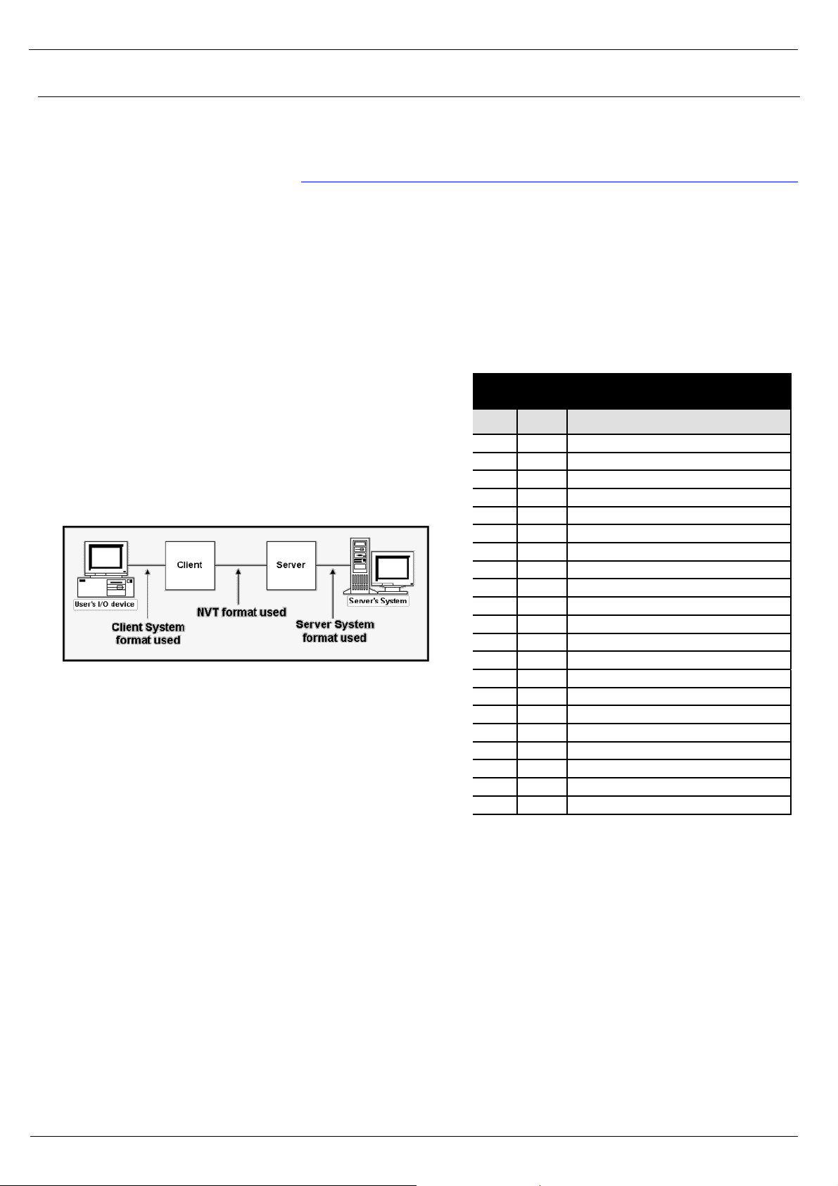
Supported NVT commands
COM-PORT-OPTION - 44 (2C)
Dec
HEX
Function
0
00
CAS_SIGNATURE
1
01
CAS_SET_BAUDRATE
2
02
CAS_SET_DATASIZE
3
03
CAS_SET_PARITY
4
04
CAS_SET_STOPSIZE
5
05
CAS_SET_CONTROL
6
06
CAS_NOTIFY_LINESTATE
7
07
CAS_NOTIFY_MODEMSTATE
8
08
CAS_FLOWCONTROL_SUSPEND
9
09
CAS_FLOWCONTROL_RESUME
10
0A
CAS_SET_LINESTATE_MASK
11
0B
CAS_SET_MODEMSTATE_MASK
12
0C
CAS_PURGE_DATA
50
32
CAS_OPT_GPIO
51
33
CAS_SET_GPIO
52
34
CAS_SET_GPIOM
:
: +100
+64
ASC_
150
96
ASC_OPT_GPIO
151
97
ASC_SET_GPIO
152
98
Not implemented, one way "answer" only
Values up to 100 Dec = Client >> Server
Values over 100 Dec = Server >> Client
CAS_ request for the device to perform a command
ASC_ device response, command performed + confirmation
Commands start with <IAC><SB> (FF FA) and end with
<IAC><SE> (FF F0).
Page 42

I/O Controller 2 Manual
HW group
www.HW-group.com
42/ 42
Description of GPIO control commands – 50, 51, 52 (32 .. 34 hex)
For direct control of I/O pins, a fixed double byte GPIO sub-command is used – 50 or 51, preceded
by the COM-PORT-OPTION 44 command and followed by the sub-option sequence.
Sub option 50 (32 hex)
Reading inputs, setting outputs bit by bit, reading the output register.
• 0 (00 hex) – Request for input states, response includes input port state.
• 16 .. 23 (10 .. 17 hex) – Set the output bit 0..7 to logic HIGH.
• 32 .. 39 (20 .. 27 hex) – Set the output bit 0..7 to logic LOW.
• 48 (30 hex) – Request for output states, response includes output port state.
Sub option 51 (33 hex)
Sets the value of the output port. In the response, the same value is returned (as read from the
internal register).
Sub option 52 (34 hex)
Command used by the I/O Controller for automatic transmission of input states, if there is a change
or after device power-up. This command does not expect a response, hence there is no value for 152
(98 HEX) in the table. The notification itself is actually an unsolicited response without a matching
request. (Theoretically, this command can be used in NVT communication, too. It differs from sub
option 51 in that the value sent to the port is modified with #X#Y#Z#W.) I/O Controller responds to
this command with the same reply as for sub option 51, that is, the response number includes sub
option 151.
The 52 (34 hex) command is often preceded by the “FF FA 2C 32 00 FF F0” sequence, which
requests a value for the I/O Controller outputs. The response includes the I/O Controller output state
(for example “FF FA 2C 33 FF FF F0”). After that, only the “FF FA 2C 34 ZZ FF F0” sequence is
sent, where ZZ is the new value for the remote outputs.
Note: To enable the input change notification function, it is necessary to set the range of
transmitted inputs with “#T: Trigger AND mask”.
- To transfer all inputs, set #T=255.
- To disable the input change transfer function, set #T=0.
Sub option 55 (37 hex)
This command is used by the I/O Controller for periodic transmission of input states. This command
does not expect a response, therefore there is no value for 155 in the table. The notification itself is
actually an unsolicited response without a matching request. It is an equivalent of the sub option 52
command for periodic transmission.
Page 43

I/O Controller 2 Manual
HW group
www.HW-group.com
43/ 42
NVT control examples
Most NVT commands have a fixed length. So, for example, if a value has a 4-byte format, and the
current setting can be read by “setting” a value of 0, this zero needs to be sent as 00 00 00 00 hex.
Setting the output byte
This command sets the output port to AA (10101010 bin).
<IAC><SB><COM_PORT_OPTION><CAS_SET_GPIO><(byte to output)><IAC><SE>
FF FA 2C 33 AA FF F0
As a response, the following sequence confirms the port settings:
<IAC><SB><COM_PORT_OPTION><ACS_SET_GPIO><(byte to output)><IAC><SE>
FF FA 2C 97 AA FF F0
Reading the inputs
Request for the input value (XX) at GPIO.
Outgoing sequence: FF FA 2C 32 00 FF F0
I/O Controller returns: FF FA 2C 96 XX FF F0
Reading the outputs
Request for the current value (XX) of the output register that controls the output pins.
Outgoing sequence: FF FA 2C 32 30 FF F0
I/O Controller returns: FF FA 2C 97 XX FF F0
Resetting the D5 output
Request to set one output bit to logic LOW, without changing other output bits.
Outgoing sequence: FF FA 2C 32 25 FF F0
I/O Controller returns: FF FA 2C 97 DF FF F0
where DF is the actual output port value (also depends on the previous port state). I/O Controller
changes only one bit but the response contains the entire port value.
Input state change notification
Unsolicited notification that reports a change at the inputs of the I/O Controller through an established
TCP connection. It can start with the FF FA 2C 32 00 FF F0 sequence – see the more detailed
description.
Outgoing sequence: none
I/O Controller sends: FF FA 2C 34 XX FF F0
where XX is the current value at the input port.
Note: The function works similarly to the incoming serial port data. Thus, in the TCP
Client/Server mode (IP address of the remote side is specified) with NVT
enabled, the device attempts to establish a connection and send the input
change information whenever a single byte of serial data is received or any
digital input changes. After establishing the TCP connection, only the current
input state is sent, NOT the whole history of changes (while the connection was
closed).
Page 44

I/O Controller 2 Manual
HW group
www.HW-group.com
44/ 42
Changing the RS-232 / RS-485 serial port baudrate
Request to change the serial port communication speed.
The current port speed can be retrieved by sending the value of 00 00 00 00 (the response contains
the current speed). If any other value is sent, the server uses it to set the serial port speed. When
converted to a decimal value, the value directly indicates the communication speed in Bauds.
Outgoing sequence: FF FA 2C 01 00 00 00 00 FF F0
I/O Controller returns: FF FA 2C 65 00 00 25 80 FF F0
Converting 00 00 25 80 to decimal, the current speed of 9600 Bd is obtained.
Keep Connection
To keep the connection alive and avoid the 50 second inactivity timeout, use the “K: Keep
connection” option in the device setup. NVT must be enabled for this to work. The connection is
kept alive by sending a NOP command (FF F1) from the I/O Controller approximately every 5s.
If port sampling is enabled with the #T: Trigger AND mask, the device sends the I/O keep command
(“FF FA 2C 37 ZZ FF F0”) instead of the NOP command (see #K, #L, #M, #N).
Are You There?
The Telnet standard supports an “Are you there” request to determine if there is a live device at the
other side. Standard Unix devices usually reply with “Yes”.
Outgoing sequence: FF F6
I/O Controller returns: <WEB51 HW XXX SW XXX SN XXX #0F *OvErr *ParErr *FlErr>
Individual XXX values are often proprietary, or can be left out in case of error messages. Sample
reply: <WEB51 HW 4.5 SW 2.3 SN 01A03B #01>
 Loading...