

Page 1

HWg-STE plus
HWg-STE plus PoE
MANUAL
Page 2
HWg-STE plus – manual
HW group
Page 2
www.HW-group.com
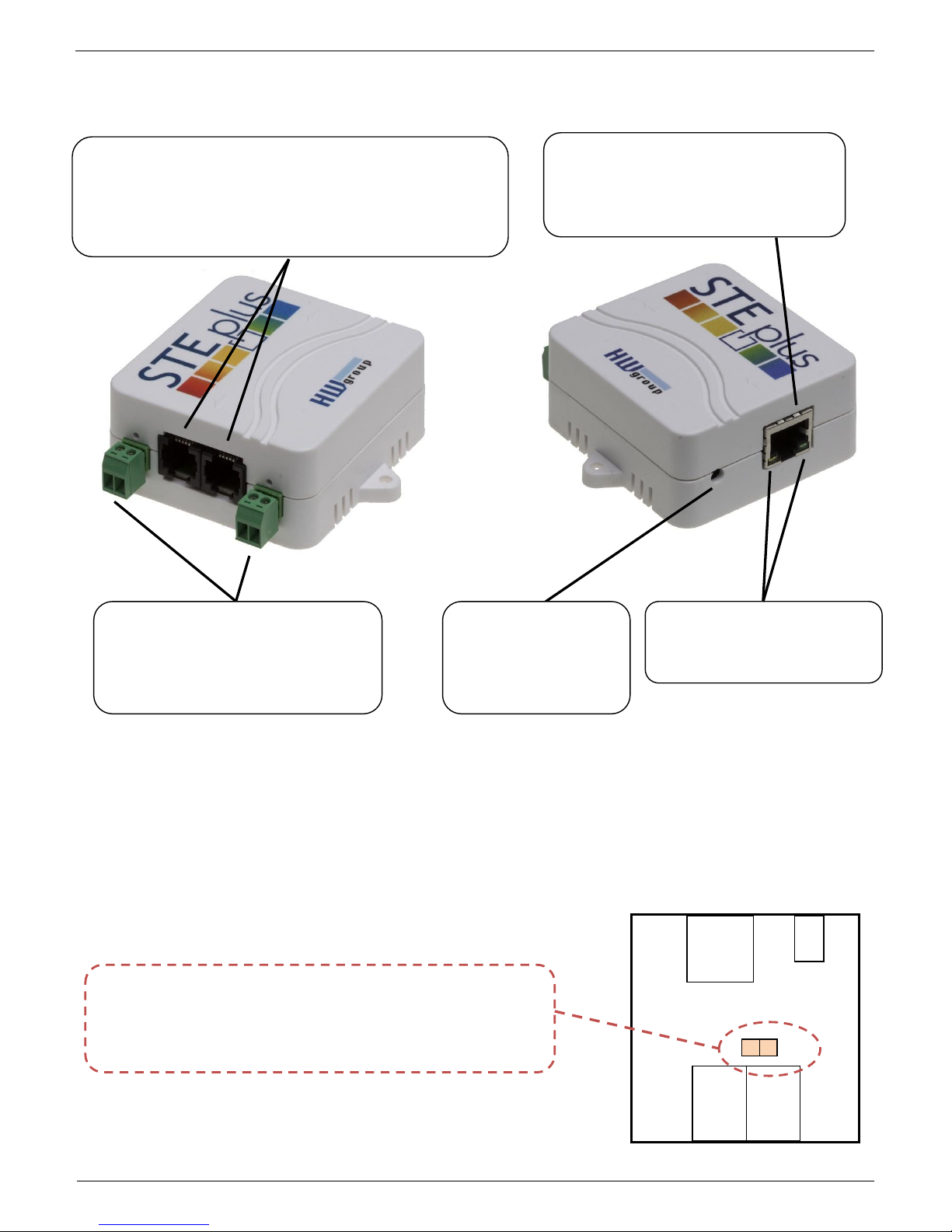
HWg-STE plus - connectors
Setting the device to its factory default
1) Turn the device off – unplug the power adapter.
2) Open the unit and set the marked jumper.
3) Turn on the device for 30 seconds only (to set the device back to defaults).
4) Turn off the device
5) Remove the jumper set in step 2
6) Turn on the device. Factory defaults settings is restored
POWER input
5V DC power supply
Use the supplied power
adapter
ETHERNET
100 Mbps
*) PoE power only for “HWg-STE PoE”
JUMPER for restoring factory default settings
DO NOT KEEP THE JUMPER PERMANENTLY SET!
SENSORS
S1 and S2 ports for connecting temperature or humidity
sensors.
Max distance 60m for both sensors in total
POWER OUT
Napájení 12V svorkovnice
Power
Ethernet
Sensors
SET
RJ45
RJ11
RJ11
LED indicators
Green: Power & Mode
Yellow: Link & Activity
Digital Inputs
2x Digital input with LED signalization
for connecting dry contact, door
contacts or relay outputs.
Page 3

HWg-STE plus – manual
HW group
Page 3
www.HW-group.com
Recommended connection options
Sensors connection options:
Smoke sensor connection:
Page 4
HWg-STE plus – manual
HW group
Page 4
www.HW-group.com
First steps
1) Connecting the cables
Connect the unit to the Ethernet (patch cable to a switch, or a cross-over cable to a PC).
Plug the power adapter in to a power outlet and connect it to the HWg-STE plus power
connector.
The green Power & Mode LED in the RJ45 connector lights up.
If the Ethernet connection works properly, the LINK (yellow) LED lights up after a short while,
and then flashes whenever data transfer takes place (activity indication).
After power up, the LINK LED flashes rapidly to indicate IP address negotiation over DHCP.
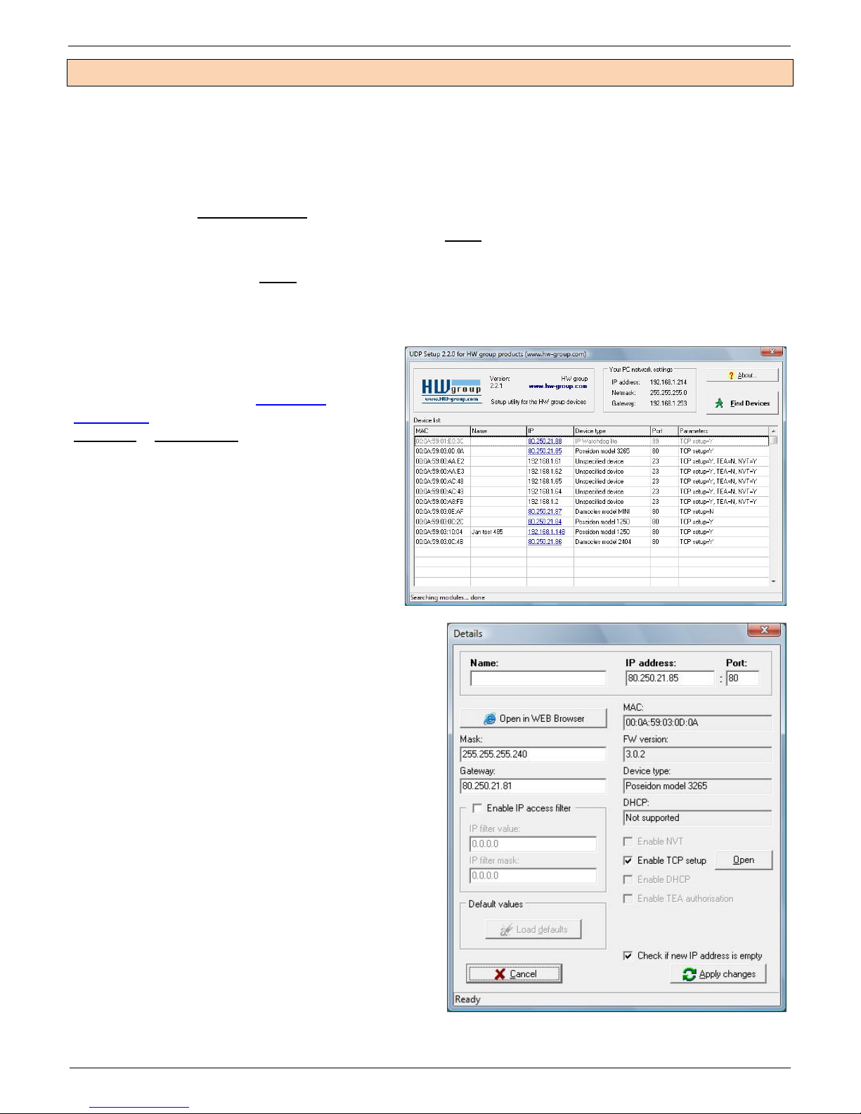
2) Configuring the IP address – UDP Config
UDP Config utility – root directory of the
supplied CD (Windows and Linux versions).
Available for download at www.HW-
group.com
Software > UDP Config.
Click the icon to launch UDP Config.
The program automatically looks for
connected devices.
To search for devices, click the Find
Devices icon.
The program looks for devices on your local
network. Double-click a MAC address to
open a basic device configuration dialog.
Configure network parameters
IP address / HTTP port (80 by default)
Network mask
Gateway IP address for your network
Device name (optional)
Click the Apply Changes button to save the
settings.
Restoring factory defaults
Right-click on the device MAC address and
select “Load default values”. Within 60
seconds after powering up the unit, factory
defaults can be restored using UDP Config.
Disconnect the power jack, connect the
jumper near the RJ11 sockets, power up the
device and wait 15 seconds. Then,
disconnect the power and disconnect the jumper. The device is ready in its factory default
configuration.
Page 5

HWg-STE plus – manual
HW group
Page 5
www.HW-group.com
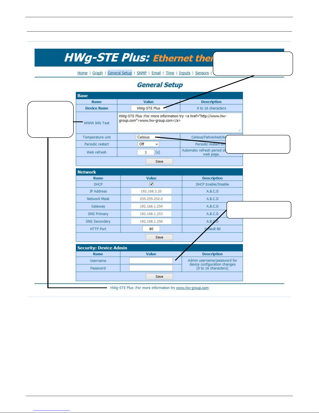
First steps
3) WWW interface of the device
To open the WWW interface of the device:
o Enter the IP address into a web browser
o Click the IP address in UDP Config
o Click the underlined IP address in UDP
SETUP
The WWW page displays current states of inputs and outputs.
Device IP address
Sensors overview
IP address / DHCP
setup
Outgoing e-mail
parameters
Sensors settings
Current sensor
reading
User-defined text for service
purposes.
Page 6
HWg-STE plus – manual
HW group
Page 6
www.HW-group.com
Device configuration
The configuration password is required for every page except the main page.
Without entering the password, it is then possible to read the current connected sensors values.
User-defined
footer. For
example,
administrator's
contact details
Device name
Identifies the device in e-mails
and SNMP
Temperature unit, for
display and alarm inputs
Password for configuration
access
Page 7

HWg-STE plus – manual
HW group
Page 7
www.HW-group.com
SNMP
Email
SNMP device identification,
same as the device name
Port for SNMP polling
SMTP server to use for
sending e-mails
Sends a test e-mail to all
entered recipients
Page 8

HWg-STE plus – manual
HW group
Page 8
www.HW-group.com
Time
Digital Inputs
Alarm settings (active/disabled)
Digital Input ID
Log0, Log1 state names.
For example - fuel tank Full/Empty or
front door Open/Closed.
Sends an email in case of
alarm if ticked
Page 9

HWg-STE plus – manual
HW group
Page 9
www.HW-group.com
Sensors
- Scans for changes in connected sensors
Note:
After connecting a new sensor or exchanging an existing one, always click Find Sensors.
Hysteresis
Hysteresis prevents receiving tens and hundreds of alarm messages about start and ending of alarm
while the value oscillates around the Safe Range threshold.
Set the value in °C or %RH, mostly using 1 to 4°C or approximately 5 %RH is enough.
You can find more on HWg websites in “AN35: Poseidon – Preventing false alarms”:
Deletes the sensor from the list
Safe Range - device sends
an email when this
threshold is exceeded
Inactivity period before and
after each alarm
Page 10

HWg-STE plus – manual
HW group
Page 10
www.HW-group.com
Portal
Portal function periodically sends data to a remote server. Sending period depends on the time set on
a server that operates the portal.
AutoPush is a function allowing sending of measured data in case of value increase/decrease larger
than AutoPush delta parameter.
Portal communication
AutoPush function and
sensitivity settings (delta –
value change)
Target portal settings with
login details
Page 11

HWg-STE plus – manual
HW group
Page 11
www.HW-group.com
Graph
Choose a sensor to show
its graph. Values are stored
on RAM memory
Safe range threshold set for
the sensor
Graph of the measured
values. Mouse-over to
show the time and value at
the point
Graph actualization period (s)
Page 12

HWg-STE plus – manual
HW group
Page 12
www.HW-group.com
System
Text list of most frequent
SNMP variables
Firmware update
SNMP MIB
Page 13

HWg-STE plus – manual
HW group
Page 13
www.HW-group.com
Technical specifications
ETHERNET
Interface
RJ45 (10/100BASE-T)
Supported protocols
IP: ARP, TCP/IP (HTTP, SNTP, SMTP, HWg-Push), UDP/IP (SNMP)
SNMP
Version1 fully supported, partially Version2
EXTERNAL SENSORS
Port / connector
S1, S2 / RJ11 (1-Wire)
Can connect
Two external temperature or humidity sensors.
One combined temperature and humidity sensor
Sensor types
Only HW group s.r.o. sensors
Sensors / range
Max 2 sensors / Max 60m in total for both sensors
DIGITAL INPUTS (Dry Contact Inputs)
Port / connector
I1, I2 / socket clamp ø2mm
Type
Digital Input (supports NO/NC Dry contact)
Sensitivity
1 (On) = 0-500 Ω (Right pin on the terminal block can be connected to 12V GND)
Max. distance
Up to 50m
Power Supply
Power Supply
5V DC / 250 mA
Connector
Jack Ø3.5 x 1.35 / 10 [mm]
PoE (Power over Ethernet)
RJ45 - IEEE 802.3af (only with “HWg-STE plus PoE” version)
LED
POWER / status
Green - power OK (status = DHCP/Local alarm)
LINK & Activity
Yellow - Ethernet connectivity
JUMPER
SET
Load defaults: Power-on with jumper ON for 30 seconds, switch off and remove jumper
Other parameters
Operating temperature
-10 to 60 °C (operating temperature range does not have to correspond with sensors range)
Dimensions / Weight
65 x 80 x 30 [mm] / 500 g
EMC
CE / FCC Part 15, Class B
EN 55022, EN 55024, EN 61000
Page 14

HWg-STE plus – manual
HW group
Page 14
www.HW-group.com
Connecting HWg-STE plus and STE Push to SensDesk portal
1) Connect the device to your network and set the network parameters (First Steps chapter in the
user manual).
2) Then open the WWW setup of the device:
Page 15

HWg-STE plus – manual
HW group
Page 15
www.HW-group.com
3) On the Home tab, click the Activate button in Portal Message section.
4) This will get you to a Portal tab and at the same time the portal function will be activated. By
clicking the link SensDesk.com: register your IP sensor a login window on
www.Sensdesk.com will be show:
Page 16

HWg-STE plus – manual
HW group
Page 16
www.HW-group.com
5) In case you already have a user account, please enter your login details and the device will be
automatically assigned to your account.
In case you do not have a SensDesk account yet, click the Register to Portal link and a
registration form will be shown.:
6) Enter the login details for your new account and a correct e-mail address. E-mail address has
to be unique for the server (cannot be already registered under another account).
Company name field allows you to create your own 3rd level domain (usually
company.sensdesk.com). A user name will be used if the Company name field is left empty.
After clicking Create new account button, a user account will be created and at the same time
a confirmation email is sent to the entered e-mail address. This e-mail contains a confirmation
link which has to be used in order to activate the account:
Page 17

HWg-STE plus – manual
HW group
Page 17
www.HW-group.com
7) By activating the account, you will be redirected to the Invitation page. At this moment, the
data sending period is set to 10 seconds to show the sensors functionality. This page is active
only for approximately 15 minutes after the activation, then the logging period changes to 15
minutes.
In your user account configuration (My Account link), you can find your Push Device
Password. This password, together with your login name, identifies the device in
communication with your account and in communication of mobile applications with SensDesk.
The password cannot be changed and for a security reason it is different to the login
password.
Page 18

HWg-STE plus – manual
HW group
Page 18
www.HW-group.com
PUSH Device Password can be used in devices to skip the logging procedure during assigning a
device to your portal account without going through the logging process.
Using the mobile phone Application
Username and PUSH Device Password can be used also for setting the
mobile application:
Contact details
HW group s.r.o
Rumunská 26 / 122
Praha 2, 120 00
Tel. +420 222 511 918
Fax. +420 222 513 833
http://www.HW-group.com
Page 19

HWg-STE plus – manual
HW group
Page 19
www.HW-group.com
 Loading...