

Page 1
HWg-SH4
User guide
Page 2

HWg-SH4
2
Safety information
Safety information
The device complies with regulations and industrial standards followed in Czech Republic and
European Union. The device has been tested and is supplied in working condition. Follow the
safety and maintenance conditions in order to keep the device in working condition.
Device housing cannot be opened if the relay contacts are connected to a power network.
Using the device in a manner other than recommended by a manufacturer may cause its
protection to fail.
Power supply outlet or a disconnection device has to be freely accessible.
The device must not be used under any of the following conditions:
• The device is noticeably damaged
• The device does not work correctly
• Unsafe parts are moving inside the device
• The device was exposed to moisture or rain
• The device was serviced by unauthorised personnel
• The power adapter or the power supply cable are noticeably damaged
Using the device in a manner other than recommended by a manufacturer may cause its protection to fail.
Switches, fuses and means of current protection have to be a part of a construction unit.
A manufacturer is not responsible for the device, unless it is used with a supplied or accepted power supply.
Page 3

HWg-SH4
3
Table of contents
Table of contents
Safety information 2
Table of contents 3
HWg-SH4 4
Basic features 5
Connectors 6
First start 7
Web interface 9
Mode selection 10
Offline mode 10
Online mode 10
Usage options 10
Control without door codes (without the keyboard) 10
Control with door codes (with the keyboard) 10
Usage options of HWg-SH4 and subordinated units 11
Adding HWg-SH4x module into HWg-SH4 system 11
Logic architecture of the system 12
Usage examples 13
Use of HWg-SH4 in small applications 13
Use of HWg-SH4 in IT environment 15
Thorough description of the WWW interface 18
General setup 18
E-mail 19
SNMP tab 22
Remote SMS tab 24
DCD server 25
User DB 26
Modules 28
Objects configuration 29
System tab 31
HWg-DCD 32
Basic features 32
Ways of communication between HWg-SH4 and HWg-DCD 32
HWg-DCD interface 34
Typical operations 37
Technical specifications 38
Connecting HWg-SH4 accessories 40
Connecting RFID readers 40
Connection of individual lock types 42
Restoring the default settings 45
Notes 46
Page 4
HWg-SH4
4
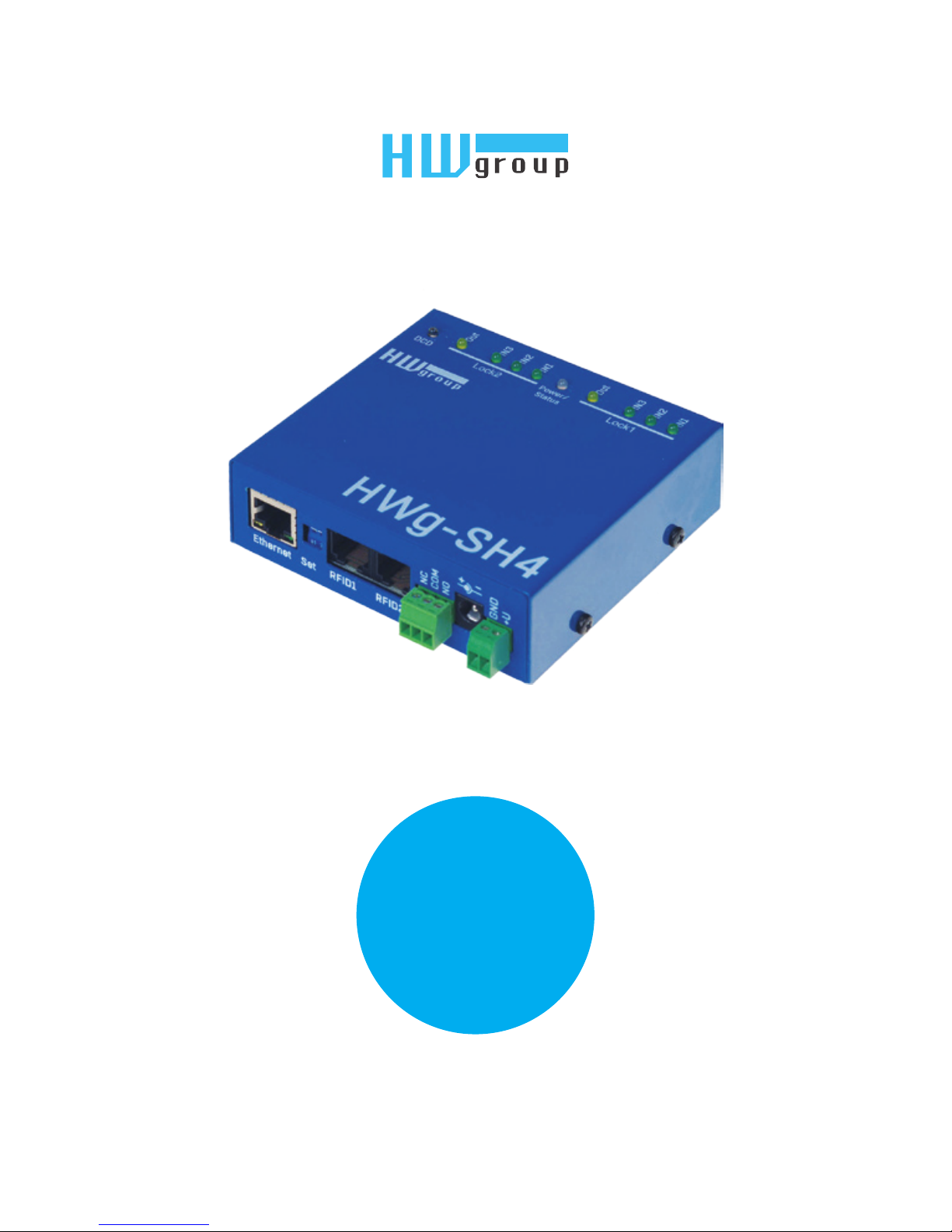
HWg-SH4
HWg-SH4
Access system HWg-SH4, together with central surveillance system
HWg-DCD, is designed for access control in data centers, technological
rooms, commercial spaces, apartment houses and offices.
Out
IN3
IN2
IN1
IN3
IN2
IN1
DCD
Lock 2 Lock 1
Power/
Status
Out
GND
+U
NO
COM
NC
Ethernet Set RFID1 RFID2 Relay Power
GND
IN1
GND
IN2
GND
IN3
GNDNCGND
NO
GND
IN1
GND
IN2
GND
IN3
GNDNCCOM
NO
Lock2Lock1
GND
+U
Power
Out
GND
+U
Power
Out
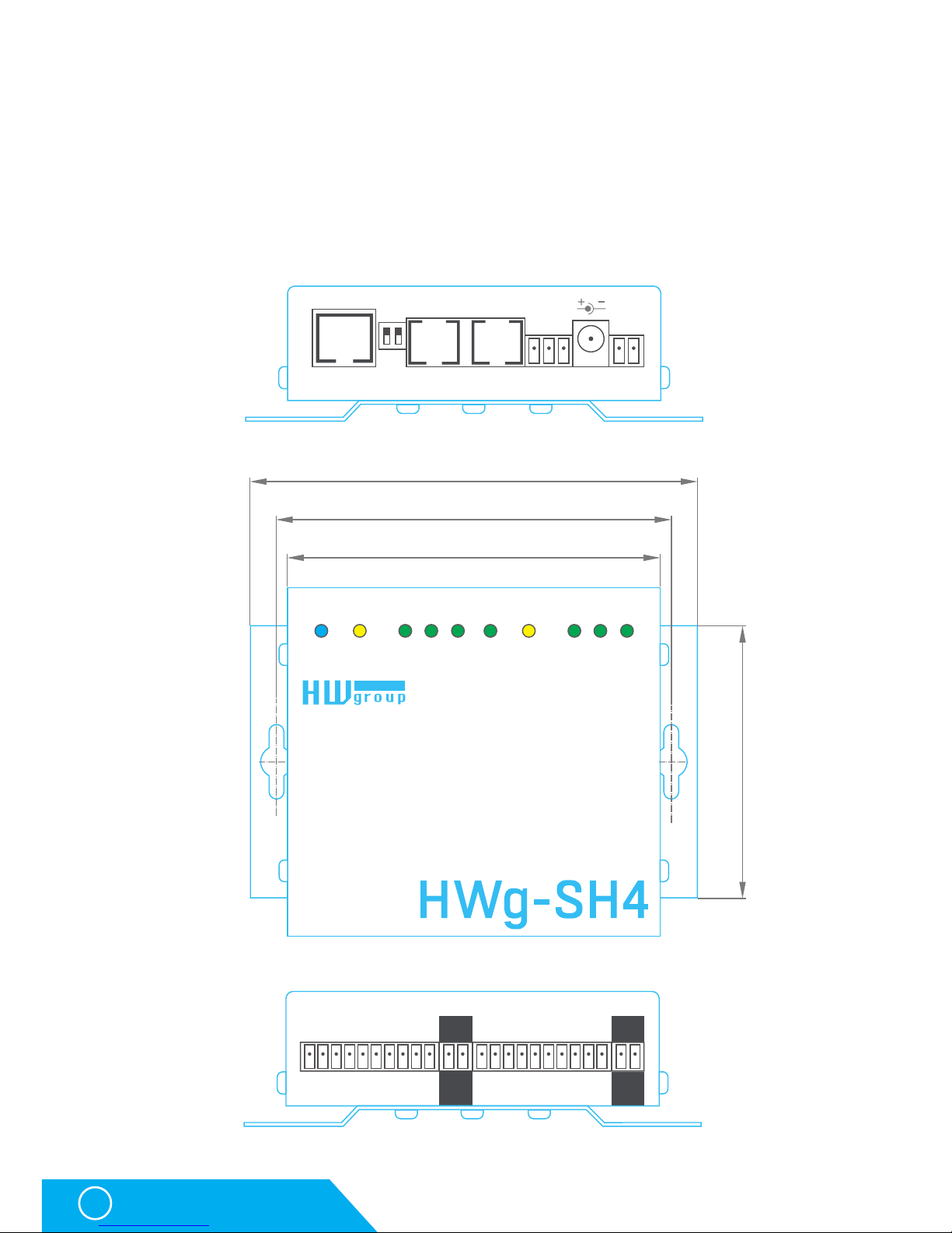
100,0
106,0
120,0
73,0
Page 5

HWg-SH4
5
Basic features
Basic features
The HWg-SH4 control unit contains two independent channels (modules) for door control
Each channel contains:
• 3 binary inputs (door contact, exit button, lock contact, etc.)
• 1 output relay switch (max. 50V/1A)
The SH4 unit can connect additional HWg-SH4e and HWg-SH4s units (max.16 units):
• HWg-SH4e units contain two independent channels (modules) for door control
• HWg-SH4s units contain one channel (module) for door control
• HWg-SH4s and HWg-SH4e units can be combined in one system
• Max. number of door channels (modules) controlled by one HWg-SH4 device is 34,
including two HWg-SH4 channels
Online / Offline mode
• Offline mode uses only the internal database of RFID tags
• RFID tags database can be managed through a built in web interface in offline mode
• Internal database allows its administrators to manage 2000 user RFID tags
Online mode uses central management server application HWg-DCD
• RFID tags database is stored simultaneously in the central management application
and in HWg-SH4 for use in case the connectivity is lost
Supports connecting two independent RFID readers (with or without keypad)
• Support of RFID readers with Wiegand or RS-232 interface
• An option to control LED or buzzers in the reader
• Door to be opened can be selected on the keypad
SNMP for remote supervising in monitoring centers supports sending of SNMP traps in case
of any action (door opening, unlocking, card read)
12V power supply input
HWg-SH4 can be installed to 19“ racks into its individual 1U holder or to a compound holder,
together with other HW group devices
Page 6

HWg-SH4
6
Connectors
Connectors
LED signalization
• Power/Status (green):
• Light confirms that the device is powered up
• Flashing indicates firmware uploading or restarting to a factory detauls
• INx (green) – light indicates triggered binary input
• Outx (yellow) – light indicates active output relay
• DCD (blue) – light indicates connection to a server with HWg-DCD
Front panel connectors
• Power – power supply connector + terminal block. Input power 9-30V
WARNING: Input power is directly connected to Power Out!
• Ethernet – interface for conecting to a computer network. Follows a 100BASE-T standard (10/100MBit)
• RFID1, RFID2 – RJ-45 socket for connecting an RFID reader with Wiegand or RS-232 interface
• Relay – signalisation relay output - max. 50V/1A. Requires a special firmware version
and the functionality depends on this custom FW release. Normally not in use
• Set – two control switches:
• DIP1 – used for restarting the device to its factory default settings (More in Device reset chapter)
• DIP2 – normally not in use
Rear panel connectors
• Lock1, Lock2 – sockets for connecting door modules. Each module consists of one switch
relay (max. 50V/1A) for a lock and three pairs of binary inputs with fixed functions
(door contact, exit button, lock contact, etc.)
• Power Out – An output for permanent power
supply of connected locks. Connected with
a Power input.
RJ45 standard B colours Function
1 - out 1
2 - out 2
3 - Txd
4 - GND
5 - in 1
6 - D0/Rxd
7 - + 12V
8 - D1
white
white
orange
brown
orange
x
blue
x
green
brown
Out
IN3
IN2
IN1
IN3
IN2
IN1
DCD
Lock 2 Lock 1
Power/
Status
Out
GND
+U
NO
COM
NC
Ethernet Set RFID1 RFID2 Relay Power
GND
IN1
GND
IN2
GND
IN3
GNDNCGND
NO
GND
IN1
GND
IN2
GND
IN3
GNDNCCOM
NO
Lock2Lock1
GND
+U
Power
Out
GND
+U
Power
Out
GND
+U
NO
COM
NC
Ethernet Set RFID1 RFID2 Relay Power
GND
+U
NO
COM
NC
Ethernet Set RFID1 RFID2 Relay Power
GND
IN1
GND
IN2
GND
IN3
GNDNCGND
NO
GND
IN1
GND
IN2
GND
IN3
GNDNCCOM
NO
Lock2Lock1
GND
+U
Power
Out
GND
+U
Power
Out
RFID connectors RFID1,
RFID2 – connections
Page 7
HWg-SH4
7
First start
First start
First steps
Connecting the cables
• Note down the MAC address of the device, printed on a sticker on the side of the device
• Check the DIP switches, eventually turn both switches off (DIP1=Off, DIP2=Off)
• Connect HWg-SH4 into the Ethernet network (with direct cable to a switches
with crossed to PCs) - RJ-45 socket
• Plug the power adapter and connect it to a connector on the device
• Green POWER LED will light up
• If the connection to Ethernet network is working, LINK LED will light up (orange light on RJ45
connector) and it then flashes during the data transmittions (Activity signalisation)
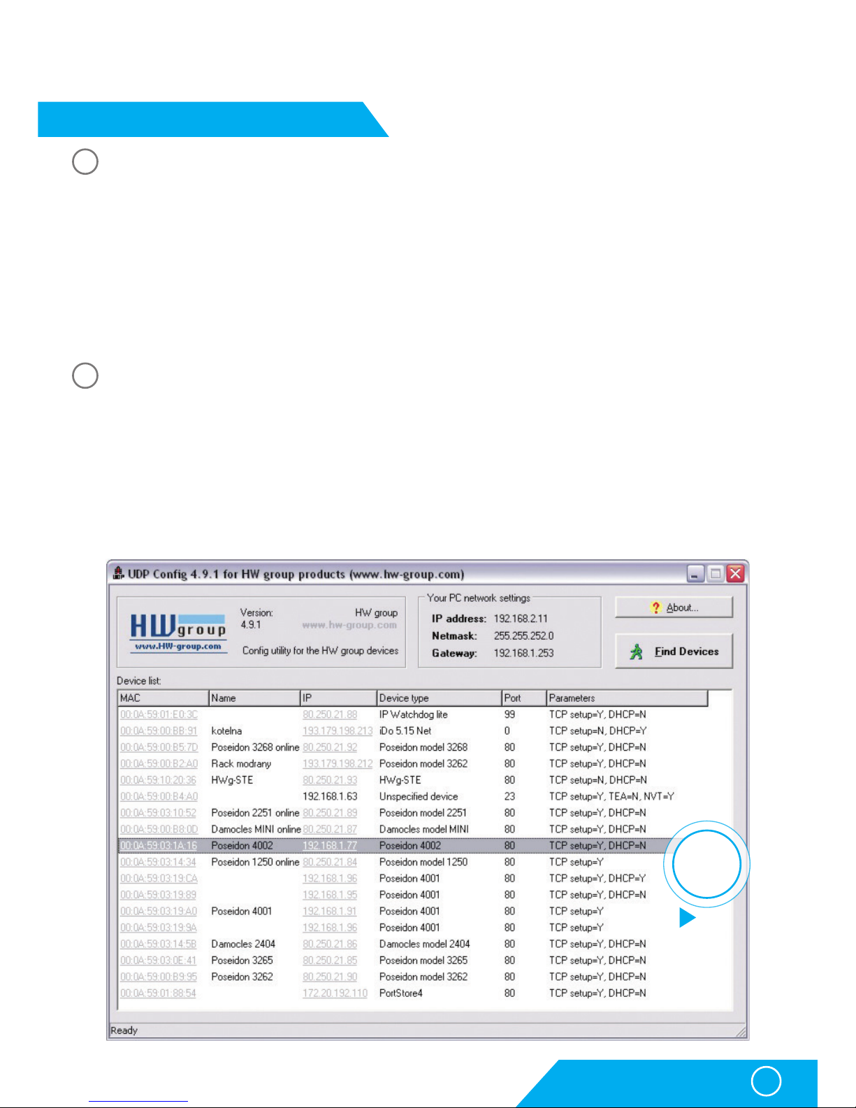
Setting an IP address - HWg-Config
HWg-Config application is located in the main folder on the attached CD (in versions for both
Windows and Linux).
This software can be also downloaded from www.HW-group.com Software -> HWg-Config.
• Start HWg-Config by clicking on its icon – software will automatically search for connected devices
Automatic search works only in a local network.
• HWg-SH4 can be identified by its MAC address (printed on the side of the device)
1
2
Double-click
for detail
see
page 8
Page 8
HWg-SH4
8
First start
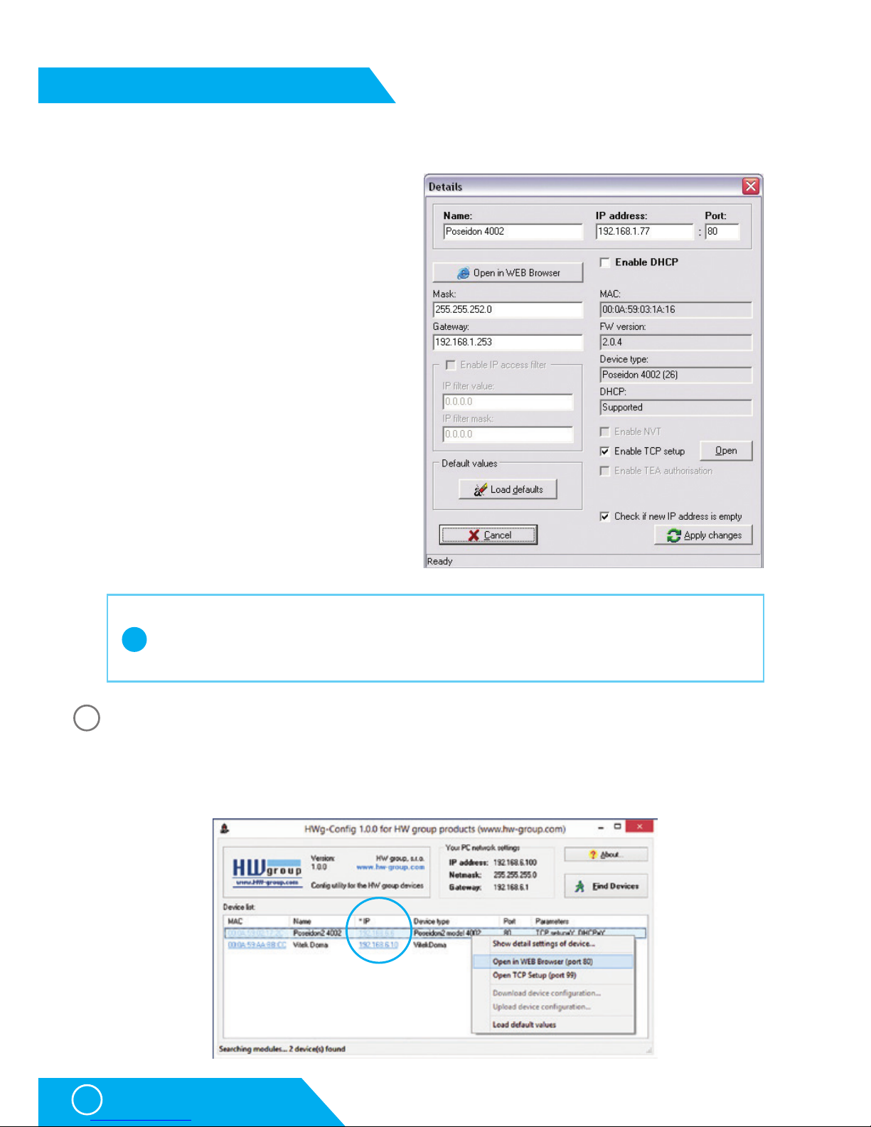
• Clicking on a MAC address of the device opens a window for setting up its basic network
parameters.
Setting network parameters of the device:
• IP address / HTTP port (in default 80)
• Mask of the network
• Gateway IP address for the local network
• Device name (You can choose the name)
Save the settings with Apply Changes button
To set the IP address you can also use:
• UDP Config for Linux
WWW interface
WWW interface of the device can be opened by one of the following steps:
• Open the device’s IP address in a web browser
• Click the IP address in HWg-Config application
First steps
3
!
Important
In case the device stops working because of a wrong configuration set, the settings
can be restored to the factory defaults. More in restoring the default settings chapter.
Page 9
HWg-SH4
9
First start
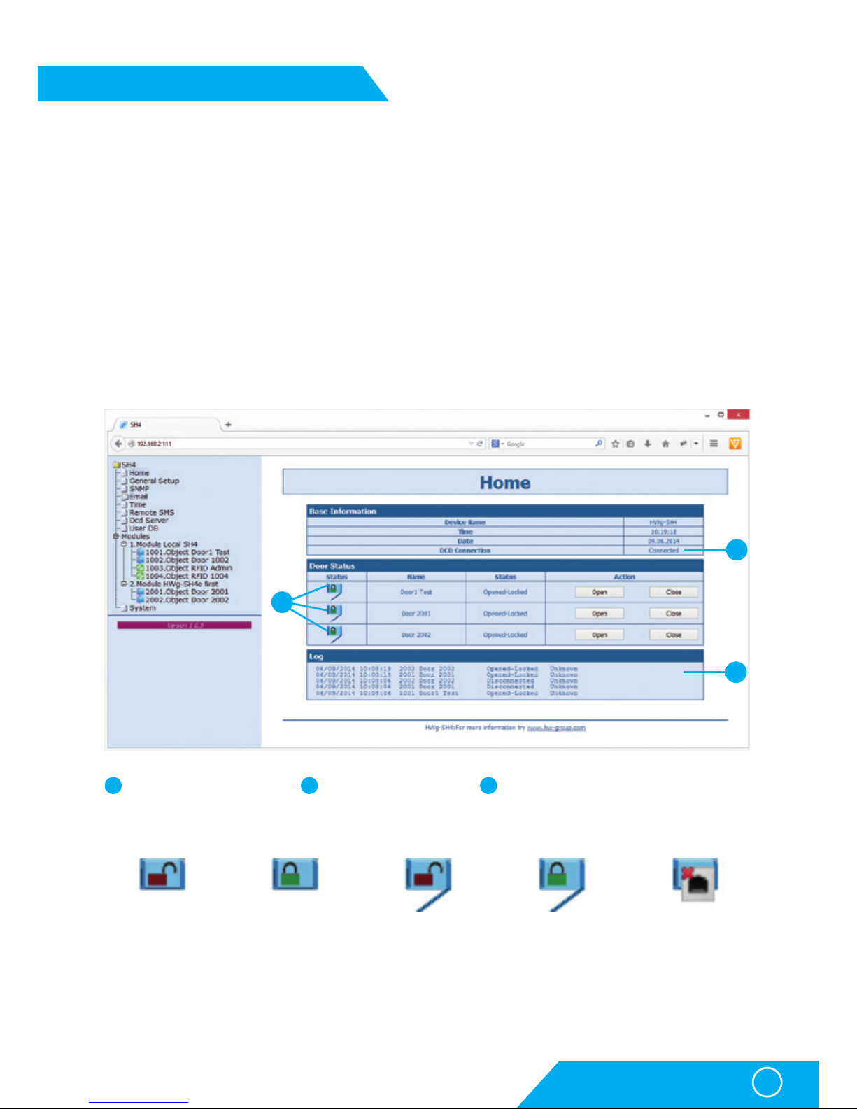
Web interface
Home actual values overview
General Setup: IP address, DNS, security options (login/password)
Email: settings and email test options
Time: time parametrs, NTP server
Remote SMS: settings and test SMS options
DCD Server: HWg-DCD server connection settings
User DB: users and offline mode rights management options
Modules: output control options and alarm settings
SNMP: SNMP / SNMP traps settings (ports and alarm messages recipients)
System: FW upgrade, configuration download options, etc.
Door closed and
unlocked – can be
opened
Door closed
and locked
Door opened
and unlocked
Door opened and
locked – door opened
by an authorized user,
waiting to be closed
Door disconnected
– connection with
module lost
First steps
1 2 3
2
1
3
HWg-DCD connection
status
Doors state & manual
control options
List of the most recent actions including
RFID tags.
Page 10

HWg-SH4
10
Mode selection
Mode selection
For testing of HWg-SH4 in offline mode you can keep the unit in the default settings, only with
connected RFID reader.
Offline mode
Offline mode enables users to start using the access system HWg-SH4 immediatelly. Users
can be added, edited or removed manually on the User DB tab. This way of use is preferred to
be used only for managing a single HWg-SH4 unit with a small number of users.
Advantage of this mode is that administrators of the system can immediately react and open
doors or manage users.
Central user management with more doors and online user database backup are not available in this mode. A manual authorization with a master tag is required for assigning available
RFID tags.
Online mode
A mode in which the access system is used together with HWg-DCD for managing users
and doors. All users are managed through the HWg-DCD application (can be run on any PC,
in case the DCD server is available on the Internet/Ethernet network). The access rights are
afterwards copied to HWg-SH4 devices.
Main advantage of this mode is its ability to manage large networks with many users, HWgSH4 units and subordinated units HWg-SH4e and HWg-SH4s. Online mode also allows administrators to work with unknown tags, that can be loaded into the system and assigned, after
the user is authorized.
Online mode requires a central server and the HWg-DCD application. However this server
does not have to be constantly online, in case a permanent survelience is required.
Usage options
Control without door codes (without the keyboard)
One standard RFID reader is connected to HWg-SH4 in basic configuration. After reading a tag
with access rights for door opening, the device unlocks the door. One RFID tag can be allowed
to open front, back or both doors connected to the unit.
Control with door codes (with the keyboard)
In this mode you need to connect the RFID keypad reader to the HWg-SH4. Each door has its
own numeric code which has to be entered and then confirmed by an RFID tag in order to unlock the door. HWg-SH4 then evaluates the code and the tag and opens each door associated
to this code and also each door with no code assigned.
Page 11
HWg-SH4
11
Usage options of HWg-SH4 and its subordinated units
Usage options of HWg-SH4 and its subordinated units
Up to 16 HWg-SH4e and HWg-SH4s units can be connected to HWg-SH4:
• HWg-SH4e units contain two independent channels (modules) for door control
• HWg-SH4s units contain one channel (module) for door control
• HWg-SH4s and HWg-SH4e units can be combined within one system
• max number of door channels (modules) controlled by one HWg-SH4 unit is 34,
including two channels on HWg-SH4
Connected modules communicate with HWg-SH4 using a TCP connection.
Subordinated units can be connected to HWg-SH4 on a configuration level. These units are
identified as modules of their master HWg-SH4.
Adding HWg-SH4x module into HWg-SH4 system
Units subordinated to HWg-SH4e and HWg-SH4s can be added through the WWW interface
of HWg-SH4 on Modules page by Add Module link.
You need to enter the following
Module Name – under this name the module will be identified in the HWg-SH4 system
and eventually also in the HWg-DCD application
Type – type of the subordinate module
IP Address – IP address of the connected unit
Username – username for communication security, defaults to „user1“. The subordinated unit
has to be reconfigured manually in case any changes are done. More information can
be found in the manual for the units
Password - password for communication security, defaults to „pass1“. The subordinated unit
has to be reconfigured manually in case any changes are done. More information can
be found in the manual for the units
Page 12
HWg-SH4
12
Logic architecture of the system
Logic architecture of the system
HWg-SH4 system is built on a hierarchy of MODULE => OBJECT => ELEMENT.
• Modules are physical devices like the HWg-SH4, HWg-SH4e, HWg-SH4s and others.
Each module contains one or more objects.
• Object represents door type objects, RFID readers and relay type objects
– (Relay type objects chapter). Each object contains one or more elements.
• Element represents the lowest point of hierarchy. Represents output relays, binary inputs,
Wiegand interface or RS-232. Elements ARE NOT defined by users!
Door type object
Door objects are used to control locks, lock sensors, for door opening detection or for
connecting exit buttons. This object consists of four elements – 3 binary inputs + 1 relay
output. Elements create a whole unit and CANNOT be managed separately.
Predefined objects:
RFID type object
Used for connecting RFID readers through Wiegand interface or RS-232 into an RJ45 connector.
Predefined objects:
Both RFID readers are connected independently and types of the readers can be combined.
You can then for example connect an EM4100 together with Mifare reader, which would allow
its users to use RFID tags they already have. Or you can use one reader with a keyboard
at the enatrance to a building and another reader withouth a keyboard at the exit.
More object types can be added on request. If you have a request on object types, please contact your distributor.
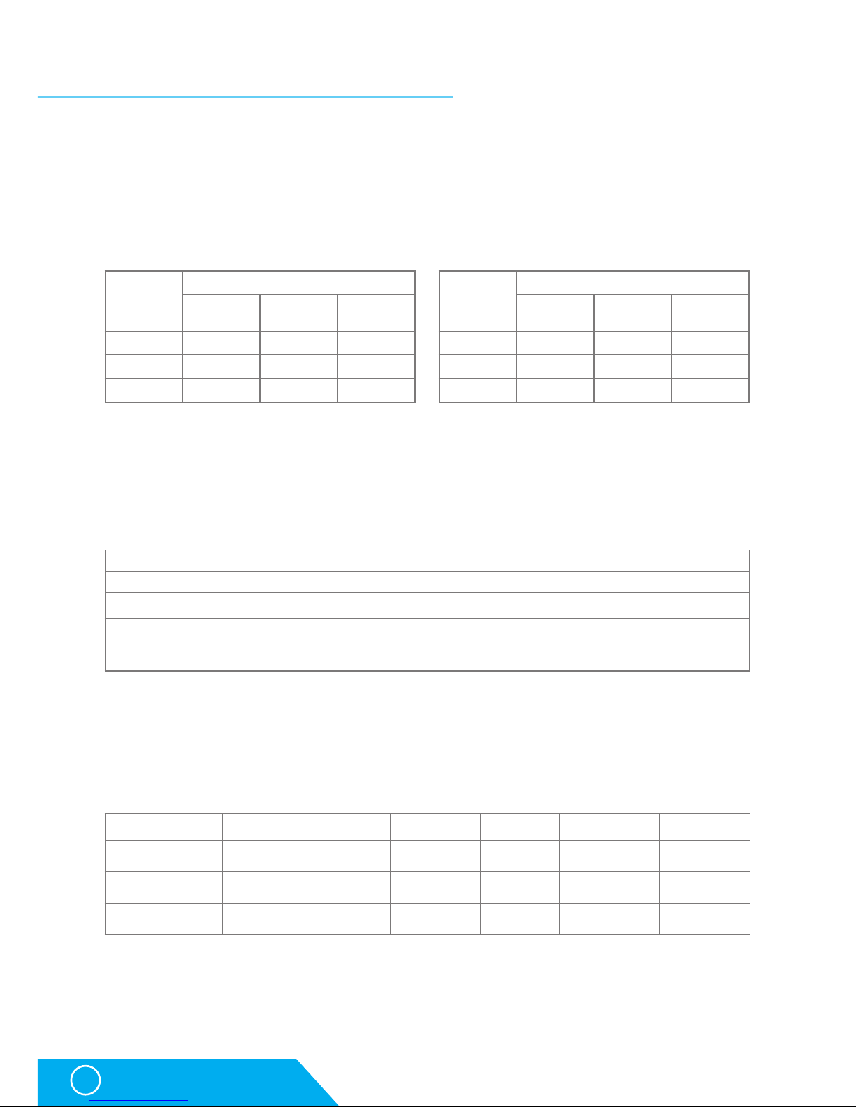
Module
Number of objects in types
Door RFID Relay
HWg- SH4 2 2 1
HWg- SH4e 2 0 1
HWg- SH4s 1 0 1
Component
Elements
Binary
Inputs
Relay
Outputs
RS-232/
Wiegand
Door 3 1 0
RFID 0 0 1
Relay 0 1 0
Element
Door Model IN1 IN2 IN3
Magnetic Lock Door contact Not used Exit Button
Soutchco R4-EM Rotary Door contact Switch Not used
Soutchco H3-EM - Electronic Locking Swinghandle Door contact Lock status Mech status
RFID reader Interface Keyboard Frequency Standard Audio output Optical output
HWg-R3 Wiegand Yes 125kHz EM4100 Yes Yes
JA-80H Wiegand Yes 125kHz EM4100 Yes Yes
RFID reader 232-M1 RS-232 NO 13,56MHz Mifare
Yes
(not defined)
NO
(not defined)
Page 13
HWg-SH4
13
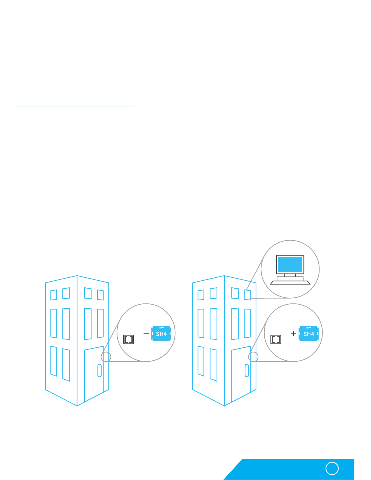
Solution without HWg-DCD Solution with HWg-DCD
Usage examples
Relay type object
Relay type objects CANNOT be controlled manually in standard version of the product.
They can be used to control signalization, to identify selected door in large rack systems
or for switching internal lighting in telco rooms, etc. To get more information on possible
usage options of the relays, please contact your local distributor with your request.
Usage examples
Using HWg-SH4 in small applications
The small applications can be for example apartment houses, small companies, or systems
using existing RFID tags.
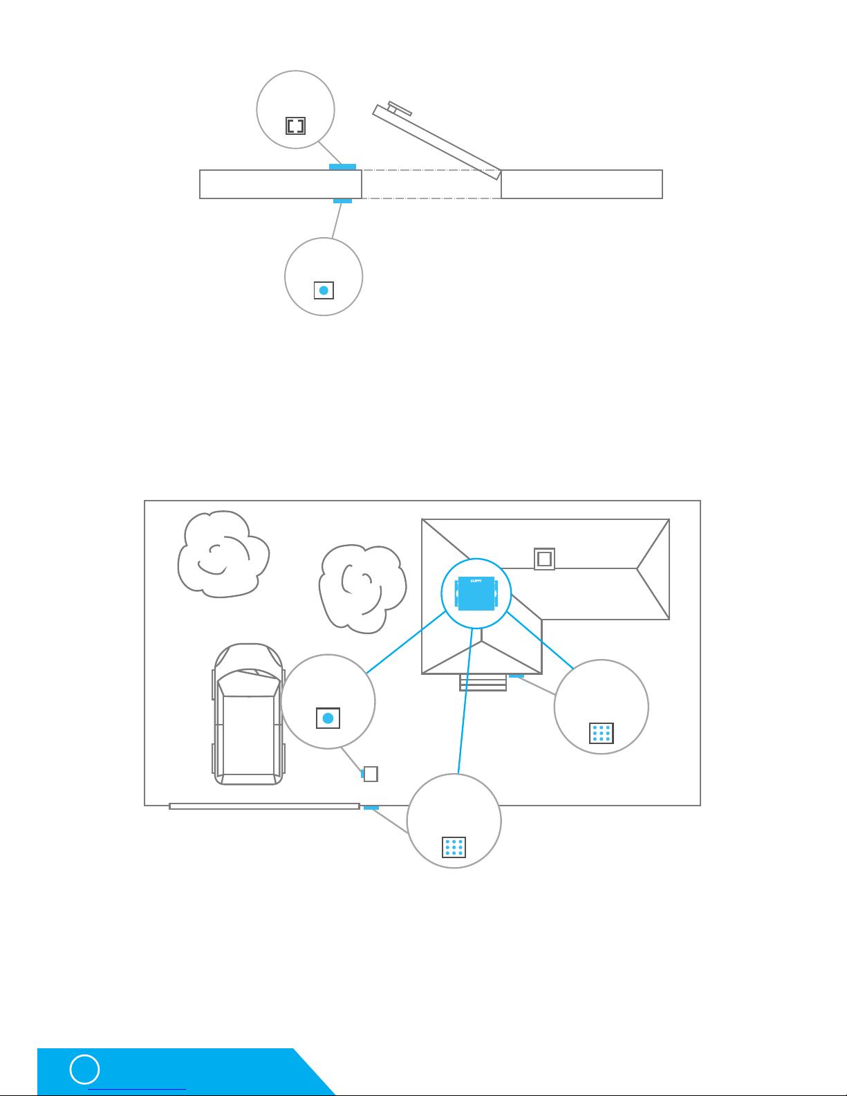
Apartment building access system
HWg-SH4 can be used as an access system for apartment houses or offices. A typical
application can be using RFID reader for access from the outside of the building, together with
an exit button installed on the inner side of the door. To enter the house you can then simply
use the RFID tag and to leave the building you can press an exit button. The door can be also
opened remotely from individual apartments. The system can also be used to control the gate
to a parking lot.
Using HWg-DCD is in such cases is optional, as it is not needed for direct administration.
However it can notably simplify registering of access tags and deactivation of the lost ones.
RFID
reader
RFID
reader
HWg
DCD
Page 14
HWg-SH4
14
Usage examples
RFID
reader
Exit button
Using the exit button
Access into a company building with a gate
HWg-SH4 can be used for entry gates on company parking lots. One RFID reader with a keyboard
would control the entry gate and another reader with a keyboard would then control access
into the building (the gate and the door require differend codes assigned). An exit button can
be used for leaving; eventually a second RFID reader can be used at the gate (can be then
used for evidence of cars parked in the parking lot). Using the HWg-DCD is optional here as well.
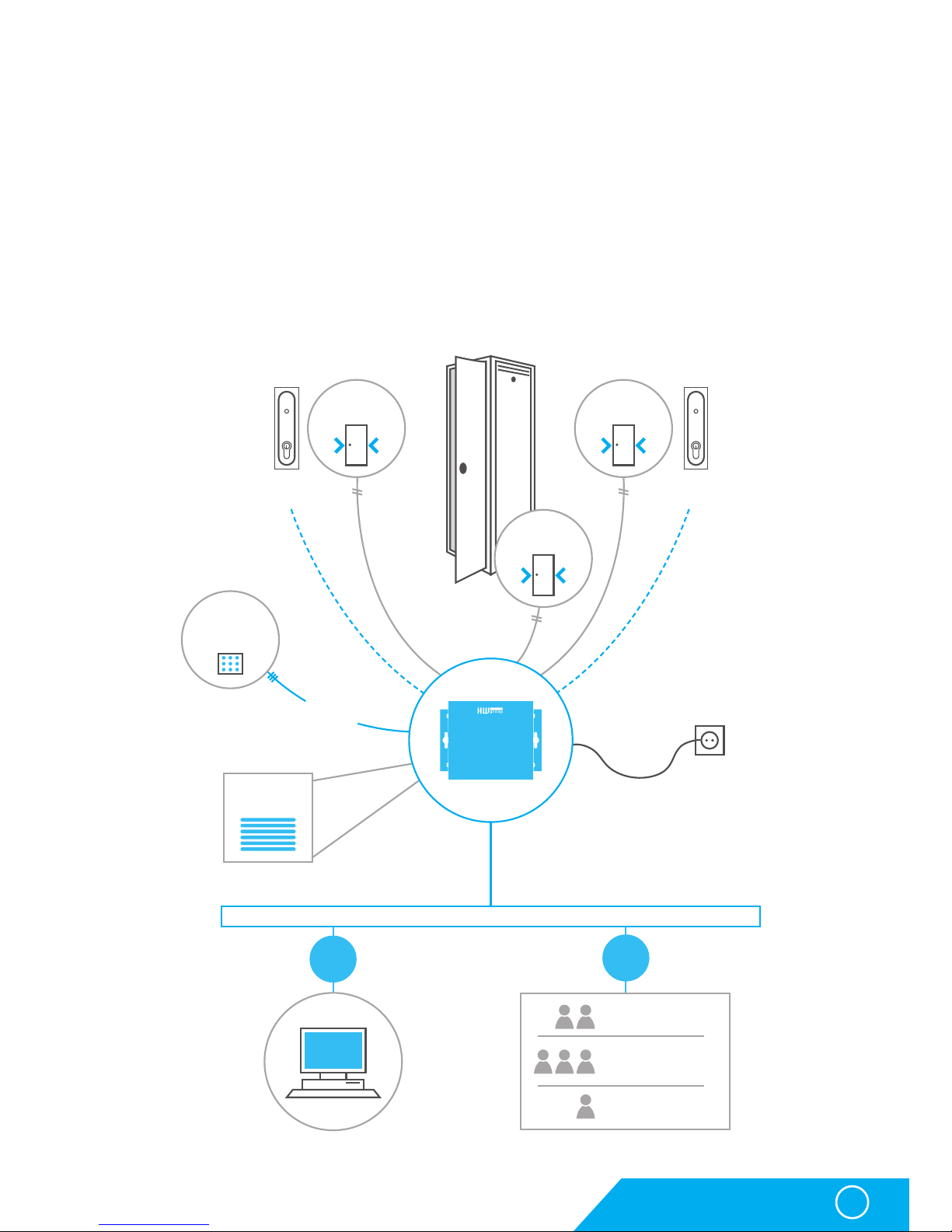
Building access system with availability for other applications
Thanks to the ability to use common RFID readers the HWg-SH4 is optimal for integration
into existing systems. For instance in many schools and libraries there are some RFID tags
systems already installed.
With HWg-SH4 you can easily assign access rights to a building by using the same tags.
Also late arrivals are then recorded, the log can also be sent as e-mail or SMS notifications.
The same can be applied in different office or storage premises.
RFID
reader
Exit button
RFID
reader with
keypad
RFID
reader with
keypad
Exit button
SH4
Page 15
HWg-SH4
15
Usage examples
Using HWg-SH4 in IT environment
A typical example is use of HWg-SH4 for access into rack cabinets and technological rooms.
Standalone solution for racks
A typical application for HWg-SH4 is in a rack cabinet, not only in individual cabinets but also
as a part of a data center. HWg-SH4 unit is then installed inside the rack and the RFID reader
is placed on one of the doors (or both). If there is only a single HWg-SH4, it can be simply
configured in offline mode through its WWW interface.
However if HWg-SH4 is installed in a data center where one unit is installed in every cabinet,
it is recommended to use the devices in online mode with HWg-DCD.
Rear door
contact
HWg
DCD
RFID
reader
with keypad
Side door
contact
Front door
contact
rear door
lock
Standard cabinet
front door
lock
RS 232
Wiegand
Users DB
Ethernet IP
WEB acces
ONLINE
mode
OFFLINE
mode
RFID CARD
Online/Offline mode
DIN KEY
SH4
Page 16

HWg-SH4
16
Usage examples
A solution using remote HWg-SH4e/HWg-SH4s units
One of the main advantages of the HWg-SH4 system is the option to use one control unit
with several subordinated HWg-SH4e or HWg-SH4s units. In such cases a use of RFID reader
with a keyboard connected to HWg-SH4 is expected. Individual doors have their own unique
numbers corresponding with a door (key/lock) number or with a number of the rack cabinet
(where the number is then used as a door code). Subordinated units HWg-SH4s or HWg-SH4e,
which directly control the door locks, are installed in individual rack cabinets.
NOTE: The units (both head and subordinated) can also use relay type objects for example for lighting
control in racks or for identification of the unlocked door. This function is not active in default.
A user enters a door code on the RFID reader’s keypad and confirms the code with his RFID
tag. The system then evaluates the request and opens the required door.
HWg
DCD
Ethernet/Internet Ethernet/Internet
EthernetEthernetEthernet
Ethernet/Internet
SH4e
X
SH4s
X
SH4s
X
SH4e
X
SH4e
X
SH4s
X
SH4e
X
SH4s
X
SH4s
X
SH4e
X
SH4s
X
RACK
RACK
RACK
RACK
RACK
RACK
RACK
RACK
RACK
RACK
RACK
RFID
reader with
keypad
RFID
reader with
keypad
RFID
reader with
keypad
SH4 SH4 SH4
Page 17

HWg-SH4
17
Usage examples
Solution with 8x HWg-SH4s
In this application the HWg-SH4 serves only as a terminal connected to an RFID reader,
while subordinate units control all the locks. A door to be opened is defined by a code entered
on the keypad.
HWg-SH4 as another access point
In this configuration the HWg-SH4 works as an access point, it controls subordinate units
and opens door as well. The door is selected with a code entered on a keypad.
RFID
reader with
keypad
HWg
DCD
Ethernet IP
SH4sSH4sSH4sSH4sSH4sSH4sSH4sSH4s
SH4
RFID
reader with
keypad
HWg
DCD
Ethernet IP
SH4sSH4sSH4sSH4sSH4sSH4sSH4sSH4s
SH4
Page 18

HWg-SH4
18
Description of the WWW interface
Description of the WWW interface
General setup
General Setup is used to set basic operational parameters of HWg-SH4.
Base section
• Device Name – (HWg-SH4) – helps to distinguish between different HWg-SH4’s in one network.
Device name can be up to 16 characters long
• WWW Info Text – text of a footer in WWW interface – useful for example for entering data
center administrator’s contact details
Network section
• DHCP – allows DHCP server to set the IP address of the unit, if available. Enabling or
disabling of DHCP depends on actual requirements of the user and the network administratior.
• IP Address – IP address of the HWg-SH4 – assigned by a network administrator.
• Network Mask – assigned by a network administrator.
• Gateway – IP address of a default gateway– assigned by a network administrator.
• DNS Primary/DNS Secondary – IP address of a DNS server – assigned by a network administrator.
• HTTP Port – port number where the built-in WWW server listens – changing the port number is
necessary for example if more devices are accessable from outside the network through
a router. Please consult any changes in this setting with your network administrator.
Port set to 80 in default.
Security: Device Admin section
• Username/Password – login details used for accessing HWG-SH4 settings
Page 19
HWg-SH4
19
Description of the WWW interface
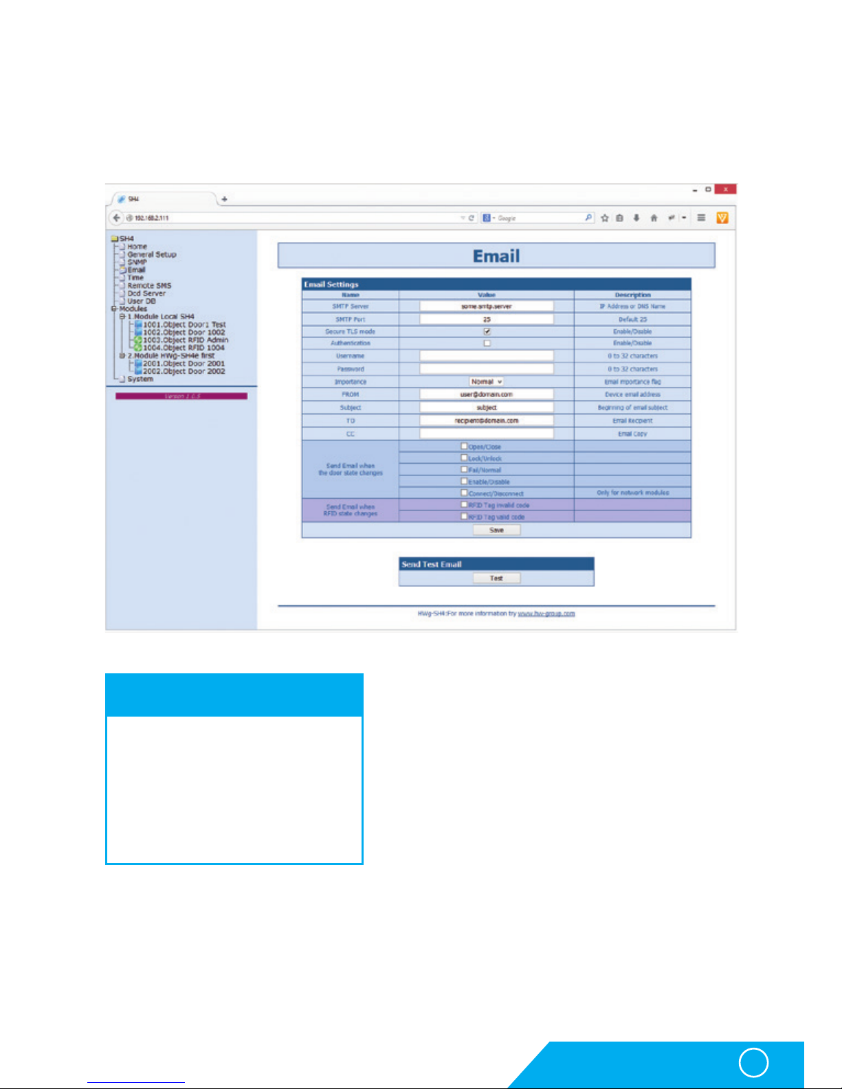
E-mail
E-mail tab defines e-mail server and parameters of alarm e-mail messages (starts or endings
of alarm states).
Check this before sending an e-mail
1. Correct Gateway IP address
2. DNS server in the network settings
3. SMTP server and its port
4. Activated authentication and correct
login name and password
5. Disabled spam filter of the mailbox
Page 20

HWg-SH4
20
Description of the WWW interface
Email Settings section
• SMTP Server – IP or domain address of a SMTP server.
• SMTP Port – port number of the e-mail server – in default port 25.
• Secure TLS mode – use this option if the SMTP server requires secured communication
using SSL/TLS.
• Authentication – tick this option in case the SMTP server requires authentication.
• Username – necessary for SMTP server authorisation. If the Authentication field is not ticked,
this is not used.
• Password – used for SMTP server authorisation. If the Authentication field is not ticked,
this is not used.
• Importance – sets priority of the e-mail messages. Necessary for filtering and further pro
cessing of alarm messages.
• FROM – e-mail address of a sender - HWg-SH4 unit. Address can be required by SMTP
servers and can be used for HWg-SH4 device identification, eventually for filtering and
further processing of alarm messages.
• Subject – Content of this field can be used for identification of the HWg-SH4, eventually for
filtering and further processing of alalrm messages.
• TO – recipient – e-mail address of alarm e-mails recipient. Only one e-mail address can
be entered.
• CC – copy – e-mail address of alarm e-mails copy recipient. Only one e-mail address can
be entered
Fields To and CC allow entering of more addresses or of a dirtribution list. For sending
e-mails to more recepients it is necessary to have a distribution list in form of a single
e-mail address (from your SMTP server administrator).
• Send SNMP Trap when the door state changes – Allows sending of notifications in case
of selected events. Available event options:
• Open/Close – Door opened or closed
• Lock/Unlock – Door locked or unlocked
• Fail/Normal – Door error – For specific lock types
• Enable/Disable – Door object powered on or off (activated/deactivated)
• Connect/Disconnect – only for network modules HWg-SH4e and HWg-SH4s
• Send SMS when RFID state changes – Allows sending of notification in case of a specific
reader object event. Available events:
• RFID Tag invalid code – unknown code loaded
• RFID Tag valid code – valid code loaded
Send Test Email section
A button for sending test e-mail messages after completing the e-mail settings.
Page 21
HWg-SH4
21
Description of the WWW interface
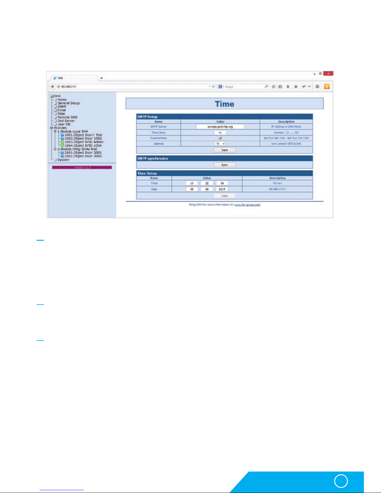
Time
On the Time tab a system time and parameters for automatical synchronisation through
timeservers are set.
SNTP Setup section
• SNTP Server – IP address or a domain address of a time server – in default time.nist.gov.
• Time Zone – sets the time zone where the HWg- SH4 is located – required for events logging.
• Summertime – allows DST switching - required for correct logging of the measured values
and events.
• Interval – interval of a time synchronisation with a server.
SNTP synchronize section
Sync is used for an immediate synchronisation with a timeserver. Can be also used to
test the entered settings.
Time Setup section
Time Setup section allows you to enter actual time and date manually, in case you cannot
use the synchronisation with a timeserver.
Page 22

HWg-SH4
22
SNMP tab
SNMP tab sets the SNMP protocol communication options and sets the target destinations
for SNMP traps.
General SNMP Settings section
• System Name – name of HWg-SH4 within SNMP
• System Location – position of HWg-SH4 within SNMP
• System Contact – HWG-SH4 administrator’s contact details within SNMP
• SNMP port – port for SNMP communication – in default 161
SNMP Access section
• Community – name of SNMP community for access to HWg-SH4 over SNMP. 2 communities
can be defined and each can have rights assigned to:
• Read
• Write
SNMP Trap Destination section
• Destination - index of a target destination for SNMP traps – only A – other indexes
are reserved for future use
• Community – name of a Community, to which the SNMP trap is sent
• IP Address – target IP address for SNMP traps
• Port – target port for SNMP traps – in default 162
• Enable – activation of the target destination – allows to block sending of the traps in bulk,
regardless the settings of individual values
Description of the WWW interface
Page 23

HWg-SH4
23
SNMP Trap Condition section
• Send SNMP Trap when the door state changes – Allows sending of notifications in case of selected
events. Available event. options:
• Open/Close – door opened or closed
• Lock/Unlock – door locked or unlocked
• Fail/Normal – door error – for specific lock types
• Enable/Disable – door object powered on or off (activated/deactivated)
• Connect/Disconnect – only for network modules HWg-SH4e and HWg-SH4s
• Send SMS when RFID state changes – allows sending of notification in case of a specific reader
object event. Available events:
• RFID Tag invalid code – unknown code loaded
• RFID Tag valid code – valid code loaded
Show OID keys table
This function prints out the full variables tree together with full SNMP OID and notes about
the type of variables. For connecting HWg-SH4 into 3rd party monitoring system you may
need a MIB file under the Download MIB file link.
Description of the WWW interface
Page 24
HWg-SH4
24
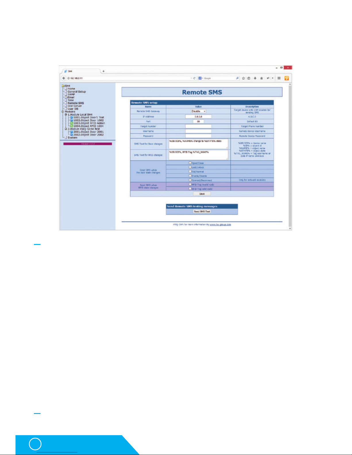
Remote SMS tab
Used to set parameters for sending alarm SMS messages via remote SMS gateway
(with netGSM support).
Remote SMS setup section
• Remote SMS Gateway – enables or disables this function
• IP Adress – IP adress of a remote gateway
• Port – TCP port of the gateway
• Target number – target number for SMS messages
• Username – username for the remote gateway. Can be left blank.
• Password – password for the remote gateway. Can be left blank.
• SMS Text – macro for creating SMS messages with information about return into the normal state.
• Send SMS when the door state changes – allows sending of notification in case of a specific
event. Available events:
• Open/Close – door opened or closed
• Lock/Unlock – door locked or unlocked
• Fail/Normal – door error – for specific lock types
• Enable/Disable – door object powered on or off (activated/deactivated)
• Connect/Disconnect – only for network modules HWg-SH4e and HWg-SH4s
• Send SMS when RFID state changes – allows sending of notification in case of a specific reader
object event. Available events:
• RFID Tag invalid code – unknown code loaded
• RFID Tag valid code – valid code loaded
Send Remote SMS testing messages section
• Test – sends a test SMS
Description of the WWW interface
Page 25
HWg-SH4
25
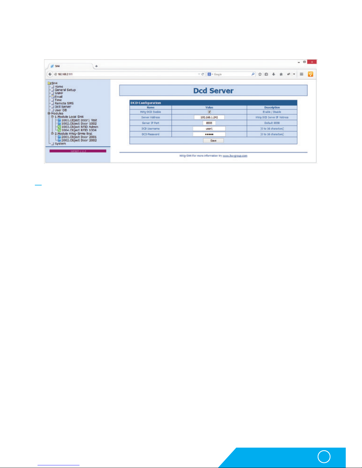
DCD server
This tab defines parameters of the DCD server connection.
DCD Configuration section
• HWg-DCD Enable – turns this function on/off (more in Functionality mode selection chapter):
• Enable – online mode
• Disable – offline mode
• Server Address – IP address of the HWg-DCD server
• Server IP Port – TCP port for HWg-DCD
• DCD Username/DCD Password – user login and password for HWg-DCD access
Description of the WWW interface
Page 26

HWg-SH4
26
User DB
A tab used for managing the user tags database
User list is not available in the online mode and it can be edited only through
the HWg-DCD application.
A log of accesses and a list of users with options of editing are displayed on this page
in the offline mode.
RFID Card log section
Shows log of the most recent events, with options of adding and removing users. This option
is very useful for managing larger amount of users.After reading the tag you can immediately
start to work with the tag’s details.
Description of the WWW interface
Page 27

HWg-SH4
27
Items in the New User section have the same importance as in the User table section.
User table section
• Index – unique identification of a user within the HWg-SH4.
• Name – firs name of the tag user
• Surname – surname of the tag user
• Card ID – unique identification of an RFID tag
• Access list – a list of modules/doors, which this user can access.
• Action – an option for editing or deleting users
Add User link
Used for adding users
Adding users
• Enter Name and Surname of the RFID tag user.
• Please use the Card Id field to enter a unique ID of the RFID tag, printed on the tag itself.
The ID can be eventually found in the RFID Card Log section after you use the tag.
You can also use an Add user link from the log itself.
• Use the Doors access field to enter the unique door IDs you want to control by this tag.
This ID is identical to object’s ID (door) in the Modules tab.
Description of the WWW interface
Page 28
HWg-SH4
28
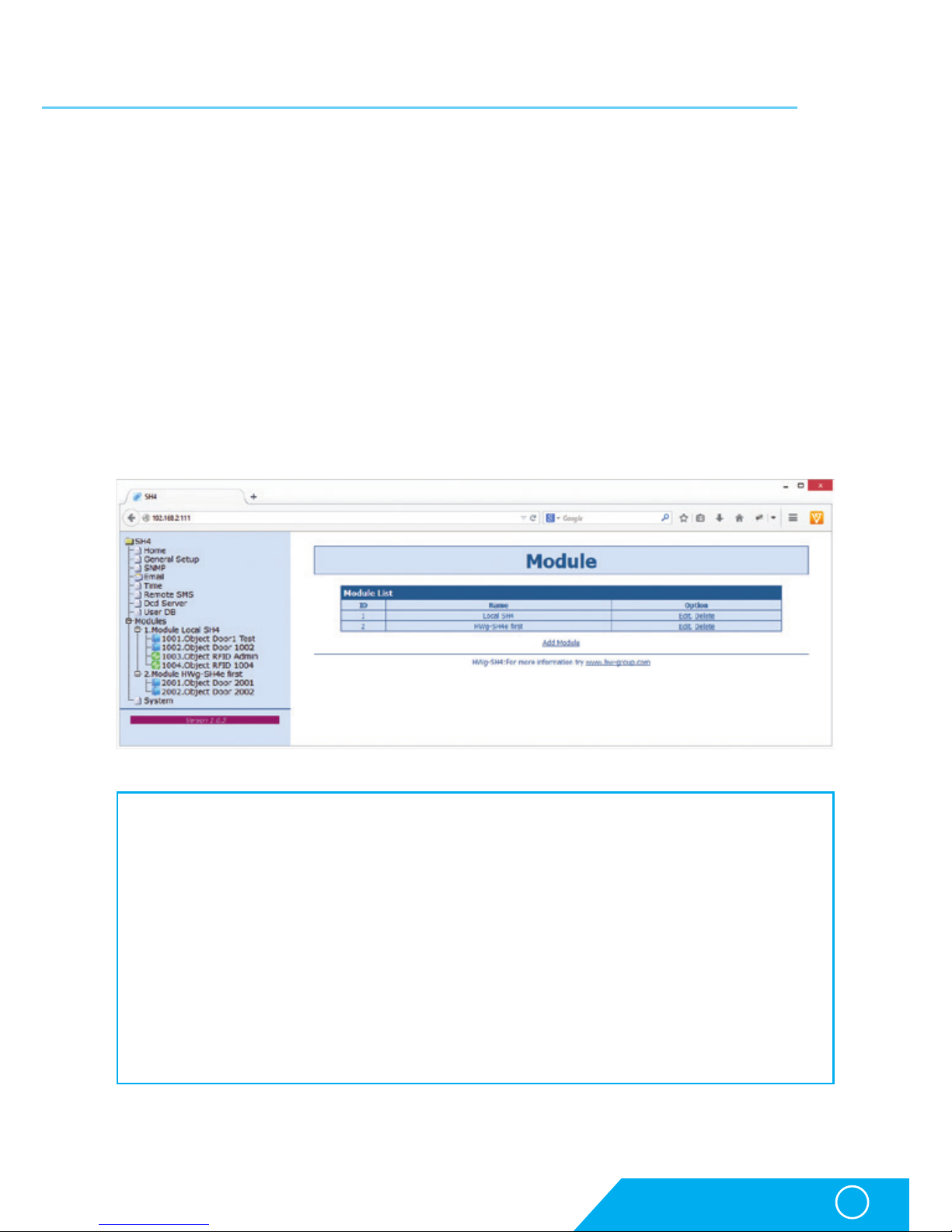
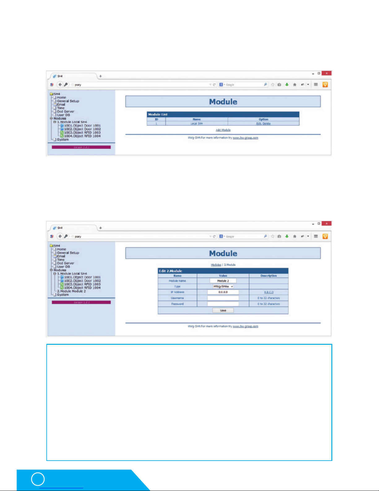
Modules
A tab for modules management, allows adding and removing of modules. Objects can be also
managed from this tab.
A list of currently connected modules is displayed on the Modules page. Only HWg-SH4e and
HWg-SH4s modules and Hermes 10 (discontinued) can be connected to HWg-SH4.
Adding modules
Using the Add Module link can add new modules.
On this page it is necessary to add:
• Module Name – the module will be identified under this name in the HWg-SH4 and HWg-DCD systems.
• Type – type of the connected module. Available options are HWg-SH4e, HWg-SH4s and
Hermes10 (discontinued).
• IP Adress – IP address of the connected module. If you enter an address of a device,
which was not assigned to any system yet, HWg-SH4 will automatically reconfigure
the device for cooperation.
• Username/Password – communication between the modules and the control unit is secured
with a user login and a password. Username and Password in the subordinated unit have
to correspond with details in HWg-SH4.
After adding a module to the system, a configuration is automatically downloaded and the objects
can be then managed as a part of the system.
Description of the WWW interface
Page 29

HWg-SH4
29
Objects configuration
This page is used for thorough configuration of objecs, as setting the locks types, RFID readers, etc.
Door type object
Description of the WWW interface
Page 30

HWg-SH4
30
RFID type object
Object section
• Enable – enables/disables the object. If an object is disabled, its configuration and states
are not being transferred to the DCD and not even to the WWW page of the device
This makes orientation in the system easier, as you can exclude objects that are not in use.
• Name – Object name makes the orientation in objects easier. Can be named for instance
as the number of door it controls, by identification number of the rack, etc.
• Type – determines the object type. Item defined in the firmware, this field is prepared
for future use
• Model – defines type of the connected accessories and therefore also types of the connected
elements
• Description – shows the elements’ connection description (wire colours can vary according
to manufacturers of locks or readers). A list of compatible locks can be found
on the manufacturer’s website or requested from your local disctributor.
Door Options section
This section sets the behaviour of door locks:
• Autolock Time – time for which the door stays unlocked / unblocked. The time is set in seconds
• Keyboard Code – sets the numeric code for the RFID reader keypad, used for unlocking
individual door locks.
Description of the WWW interface
Page 31

HWg-SH4
31
System tab
System tab offers access to main system details such as uptime and firmware version.
It also offers restart options or tools for firmware update.
Download section
• Backup configuration – by clicking the link you can save the actual HWg-SH4 configuration
and later restore this configuration or load it to another device
• SNMP MIB Table – SNMP MIB file – address of a MIB file, containing definition of SNMP variables
• TXT list of common SNMP OIDs – a list of the most frequently used OIDs from the MIB chart
System section
• Version – firmware version. Diagnostic information for troubleshooting
• Compile time – firmware compilation time. Diagnostic information for troubleshooting
• Build - diagnostic information for troubleshooting
• UpTime – uptime since last power-on or reset of the device Diagnostic information
for troubleshooting.
• Demo mode – activated demo mode disables changes in configuration of your device
Visitors can freely browse all pages of the WWW interface in this mode but they cannot
make any changes. The device can be then made available on a public network without
any risk of problems with settings.
• Upload Firmware or Configuration – allows users to upload new firmware or a configuration
file. Uploaded configuration may not be compatible in case the difference between
firmware releases is too large.
Factory Default section
Restores the factory default settings. The default IP address is 192.168.10.20 and both login
and password are not set.
Description of the WWW interface
Page 32

HWg-SH4
32
HWg-DCD
HWg-DCD
The HWg-DCD application is used for centralised management of users and end points (objects)
of the HWg-SH4 access system. This application offers easy and fast adding and editing of
objects, with options for sorting by groups or locations. It also offers a register of users with
options for sorting into groups, and a complete control over access rights for doors and users.
Basic features
• Quick object overview (open/closed, unlocked/locked, set/open)
• Manual door control
• Options for sorting objects into groups by locations
• Options for sorting objects into groups by types (door)
• Complete management options for objects, including the locks settings, RFID readers settings, etc.
• User accounts management with e-mail addresses and phone numbers log.
• Sorting users into groups
• Drag and drop options for managing users and objects
• Remote management options in client/server system
• Server application with extended logging capacity.
• Access log and event log mirroring from HWg-SH4 to HWg-DCD
• Communication between the device and HWg-DCD based on events or periodical checks (Heartbeat)
Ways of communication between HWg-SH4 and HWg-DCD
Communication between HWg-SH4 and DCD is done via a closed and encrypted protocol of
HWg-DCD, based on the TCP/IP principle where the HWg-SH4 is a TCP client. Each unit creates
a permanent TCP connection after it is powered on and in case that any event appears
on the side of HWg-SH4 (loaded card, entered code, door opened…), the device notifies the server.
The device also periodically notifies the server confirming that all functions are working
correctly (heartbeat). Administrator of HWg-DCD will immediately know about any change
of states, but also about connectivity losses.
After the device is connected, the HWg-DCD downloads configuration from the device. Based
on that it creates a template and changes the configuration according to actual settings of the
device. These parameters can be confirmed or changed by administrators.
Page 33
HWg-SH4
33
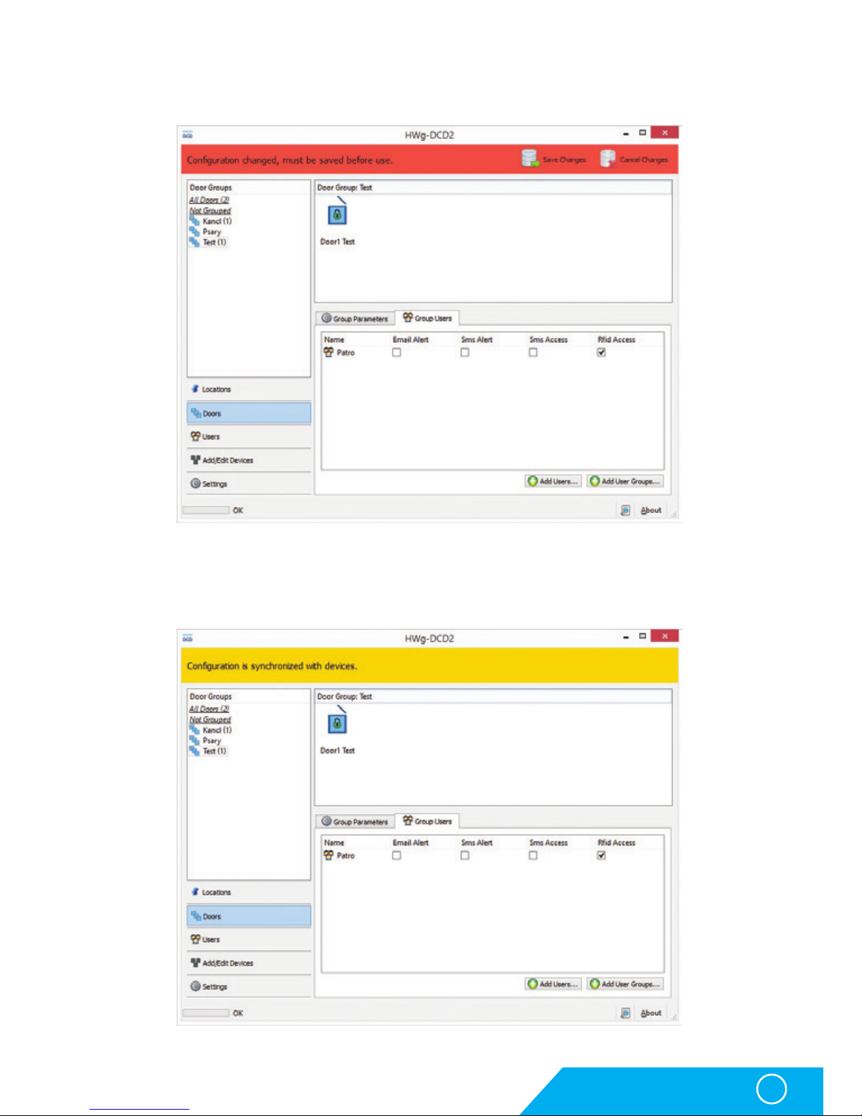
HWg-DCD
Configuration changes are processed in both DB and the device at the same time in order
to make work with HWg-DCD more fluent.
Connection between HWg-SH4 and HWg-DCD is caused by any action on the side of the
HWg-SH4, or randomly in 30-90s period. Any changes done in HWg-DCD will then be applied
in less than 90 seconds. Information window shows details about the synchronization.
Page 34
HWg-SH4
34
HWg-DCD
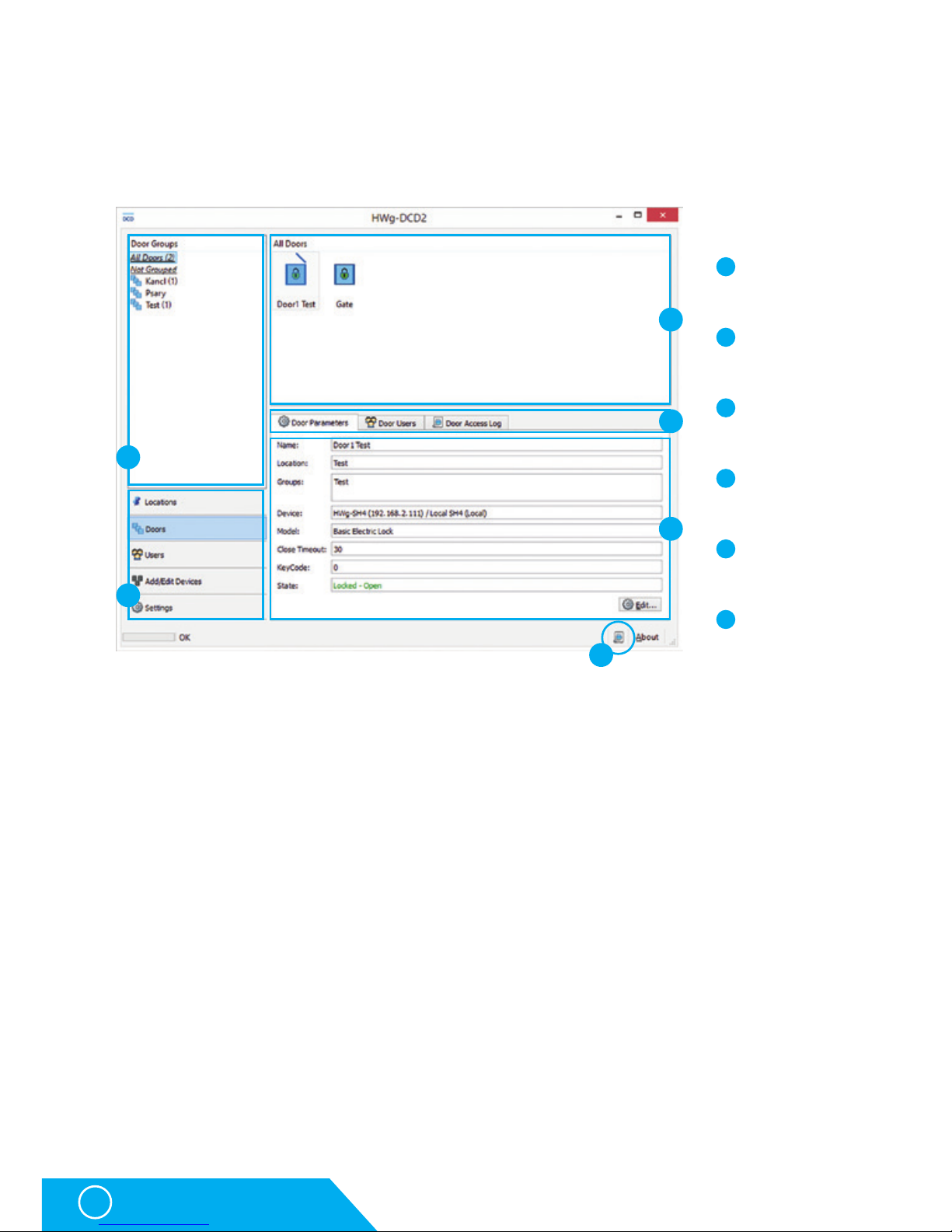
HWg-DCD interface
Visual interface of the HWg-DCD is designed to be intuitive and familiar to most users.
You can control the application by dragging items between the windows or by using the
context menu available under right-clicks on items or in the window field.
View selection
Allows switching the view in HWg-DCD and it is the most important part of the application.
• Locations – Locations define the physical position of objects (doors, readers, relays). Allows
defining and grouping of components placed at the same locations. Door objects connected
to the same device can be placed in different groups; also door and reader objects can be
placed in same or different groups based on their real position.
Groups can be created in more levels, but each object can be placed only in one location.
Locations can have sublocations to be more accurate:
• Server House Brno
• Building A
• 1st floor
• Section A
• Section B
• Row 1
• Row 2
• 2nd floor
• Buildning B
• Server House Praha
3
5
6
1
2
3
5
6
4
1
2
4
Group window
View selection
Objects window
Properties window
Events log
Parameters tabs
Page 35

HWg-SH4
35
HWg-DCD
• Doors – Shows individual door type objects and allows administrators to group the objects into
logical units (HW group Praha, HW group Wien, HW group London, etc.). One door can be part of any
number of groups. This view does not show RFID or relay type objecs, only the door objects.
• Users – shows individual users and allows administrators to group them into logical units
(HW group, workshop, sales, etc.)
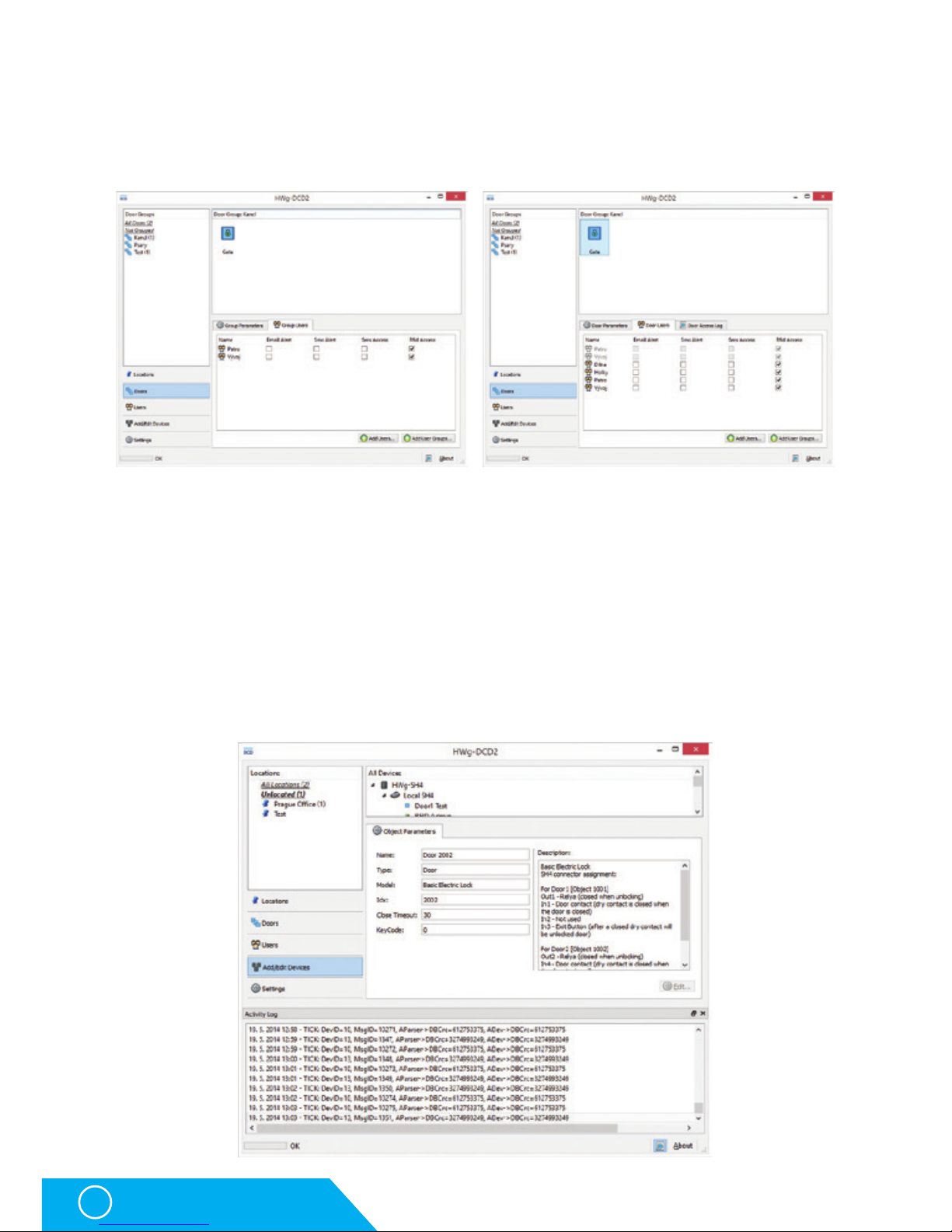
• Add/Edit Devices – Used for adding and editing devices and objects and for their sorting
by locations. Groups shown in the Locations and Add/Edit Devices lists are identical, but offer
different view on the situation. Add/Edit Devices does not show the locations of devices, but
locations of HWg-SH4 and HWg-SH4e control units.
• Settings – Basic settings of the application, server’s service IP address (In case the service
is not running on the same device as user GUI), behaviour of GUI for folders browsing and
default display options.
Group Window
Group window displays the trees of locations, doors and users. Default view is All xxxxx
(All doors, All users, All devices, All Objects). In the objects window you can then see contents
of the selected group. All xxxxx and Unlocated (Ungrouped) groups are system groups and
cannot be removed.
Objects window
shows a complete list of objects connected to a selected group.
Door closed and
locked
Door disconnected
– communication lost
Door opened and
locked – legally
opened, can be now
closed
RFID reader
Door opened,
unlocked
RFID reader with
admin rights
Door closed and
unlocked – can
be opened
Error in
communication with
RFID reader
Door error
– forced entry
Error in
communication with
RFID reader with
admin rights
Clicking a door icon will open the connected door. Right clicking the icon will open a context menu
with options.
Page 36
HWg-SH4
36
HWg-DCD
Parameters tabs
The tabs are used to switch between properties of objects and groups where it is relevant.
Events log
Events log in the HWg-DCD is useful for calibrating the application or for dealing with client’s
problems with the system. More information can be found in Application note on the manufacturer’s websites or on request from your local distributor.
Settings window
Settings window shows an overview of settings and access right and offers an option to edit
the contents. Settings are different for various view options and for individual objects.
Also the switching parameters can be changed as needed.
List of group parameters Object properties
Page 37
HWg-SH4
37
HWg-DCD
Typical operations
Adding and removing groups
To add or remove a group switch to a required view and with a right-click into the group
window, or directly on a group name, open a dialog for adding/removing groups.
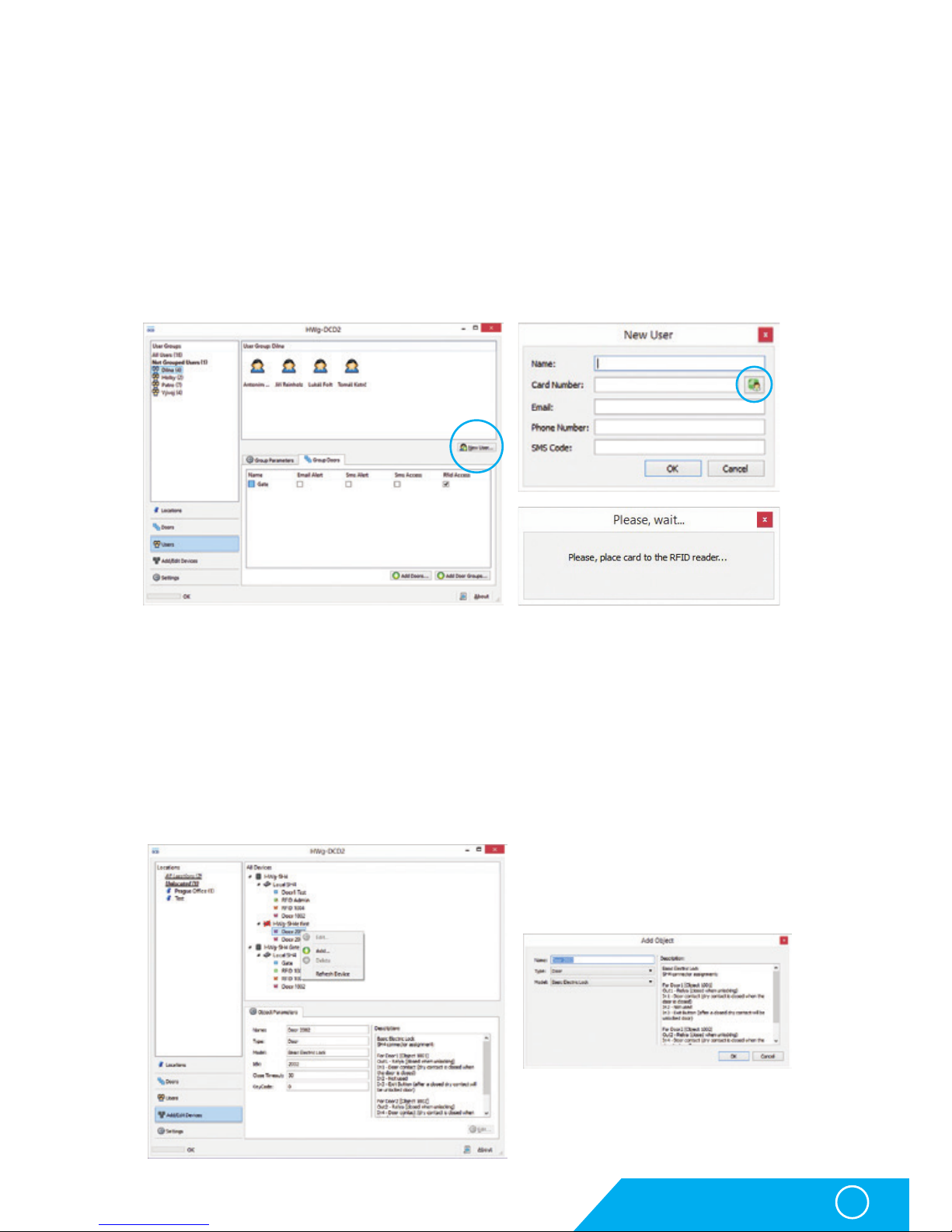
Adding users
Go to Users tab by switching the views and with a New User button open the New User
window. Card Number field can be filled in manually or after clicking the administrator RFID
reader icon a card with admin rights can be read.
Erasing and editing accounts
Users can be edited after clicking the Edit button on the User parameters tab. Users can be
erased by selecting an account and pressing a Delete button.
Adding devices
In the tabs list you can activate Add/Edit Devices mode. You can then see all subordinated
devices in the objects window. Choose an object and open an adding dialog window by right
clicking on this object.
Page 38
HWg-SH4
38
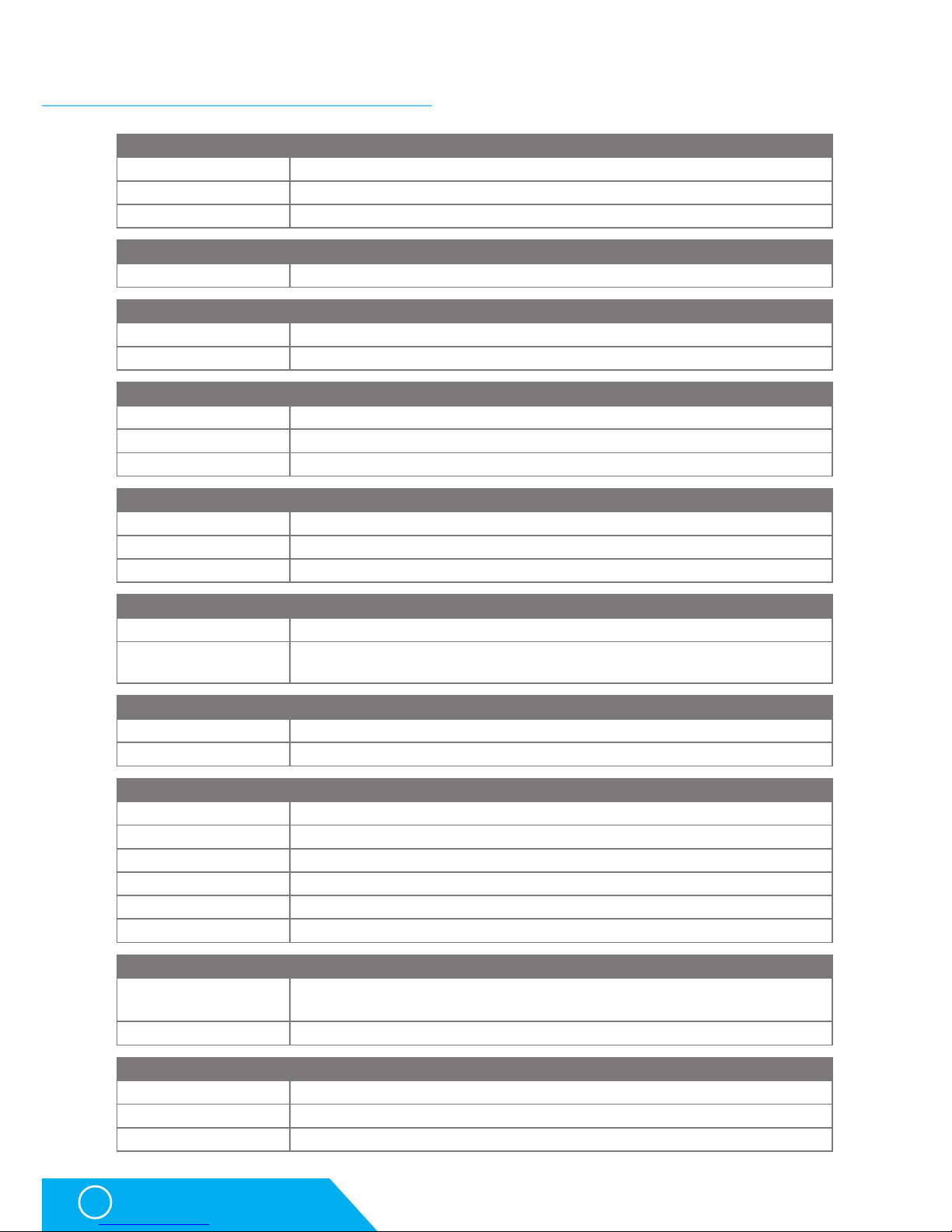
Technical specifications
ETHERNET
Interface RJ45 (100BASE-Tx) – 10/100 Mbps network compatible
Supported protocols IP: ARP, TCP/IP (HTTP, NTP, SMTP, HWg-DCD), UDP/IP (SNMP)
SNMP compatibility Ver.1.00 compatible, partial ver.2.0 implementation
User database
Size Max. 2000 users
RFID Reader
Type Wiegand or RS-232
Connector 2xRJ-45
DI - INPUTS for Dry Contact
Type Digital Input (supports NO/NC Dry contact)
Sensitivity 1 (On) = 0-500 Ω
Max. distance Up to 50m
OUTPUTS
Max. voltage 60V AC/DC
Max. load Max 1A, up to 60VA/24W (0.5A/48V)
State Power up state (no state restart memory)
POWER input
Port POWER 12V DC
Power input
12V DC / 2,5W (typically 250 mA)
Connectors: Jack (barrel, inner 2.5 mm outer 6.3 mm) + Terminal Block
POWER output
Voltage Power Out = Power IN
Current / Connector Max. 150mA / Terminal Block
LED Status indicators
POWER (RJ45 + top) Green - power OK (top), Ethernet enabled (RJ45)
LINK & Activity (RJ45) Yellow - Ethernet connectivity
Setup / Alarm Red
Inputs Green
Outputs Yellow
HWg-DCD Connection Blue
DIP SWITCH
DIP1: Setup
OFF = Normal state
Load defaults: Set ON, power-up device, toggle 3 times during first 5 seconds
DIP2: Security MUST be OFF
Physical parameters
Temperature range Operating: -30 to +85 °C / Storage: -35 to +85 °C
Dimensions / Weight 145 x 90 x 45 [mm] / 225 g
EMC FCC Part 15, Class B, CE - EN 55022, EN 55024, EN 61000
Technical specifications
Page 39

HWg-SH4
39
Technical specifications
Power supply output
HWg-SH4 offers PWR OUT for power supply of connected sensors and detectors, for instance
smoke detectors.
• NO and NC notes apply for normal state - 0 (Off) and for switched off devices
• In case the output is in state 1 (On), the “Normally Open“ (NO) output relay is connected
• Signalisation: set / open states of the relay are distinguished by a LED light
• Isolation: Switch contacts are galvanically isolated from the rest of the device.
Inputs - DI inputs for binary contacts
Inputs - DI inputs for binary contacts Dry contacts or GND
pins can be connected to terminal blocks on digital inputs.
Inputs are galvanically connected to the 12V power supply.
Unoccupied/Inactive input is marked as „O (Off)“.
Active input is marked as „1 (On)“
Relay outputs
PWR OUT = PWR IN
PWR IN
PWR
OUT
GND
+U
9-30V
GND
+U
PWR
OUT
GND
+U
NO NC
NO
COM
PWR OUT
12V
IN1
GND
Voltage on PWR OUT is equal to
the input voltage of the HWg-SH4!
!
Page 40

HWg-SH4
40
Connecting HWg-SH4 accessories
Connecting HWg-SH4 accessories
Connecting RFID readers
RFID readers can be connected to HWg-SH4 by a pair of RJ45 connectors. Only one reader can
be connected to each connector (object). Types of connected readers can be different.
Connector RJ-45F DN93612 is supplied with HWg-SH4 as an optional accessory.
Connecting HWg-R3 RFID reader
RJ45 standard B - colours Function HWg-R3 JA-8H
white orange
1 - out 1
gray yellow
orange
2 - out 2
purple x
x
3 - Txd
x x
blue
4 - GND
black blue
x
5 - in 1
x x
green
6 - D0/Rxd
green green
white brown
7 - +12V
red red
brown
8 - D1
white brown
Take off approximately 3cm of the
outer isolation of the connecting
cable and draw the cable through
the top part of the connector
- DN93612.
Then place the individual
conductors of the cable to their
positions on the connector’s
top part.
1 2 3
Page 41

HWg-SH4
41
Connecting HWg-SH4 accessories
Cut off the spare parts of the
conductors just at the side
of the top part.
Attach the head part to the
connector’s body and press
the parts firmly together.
Use the supplied strap to prevent
the cable from being pulled out
of the connector. Cut off the spare
part of the strap.
The metal body of the connector
can be used to press the parts
together to properly cut
the conductors through.
Check the correct functionality
of the reader.
4 5 6
7 8 9
10 11 12
Page 42

HWg-SH4
42
Connecting HWg-SH4 accessories
Connection of individual lock types
Basic Electric Lock
Connection rules for different elements
• Out1 - Relay (closed when unlocking)
• In1 - Door contact (dry contact is closed when the door is closed)
• In2 - Not used
• In3 - Exit Button (closing the dry contact unlocks the door)
Connection with exit button included (optional) + detail of connection
Connecting lock E-lock BeFo 512
Page 43

HWg-SH4
43
Connecting HWg-SH4 accessories
Connecting E-lock XPO-211 lock + detail of connection
Page 44
HWg-SH4
44
Connecting HWg-SH4 accessoriesa
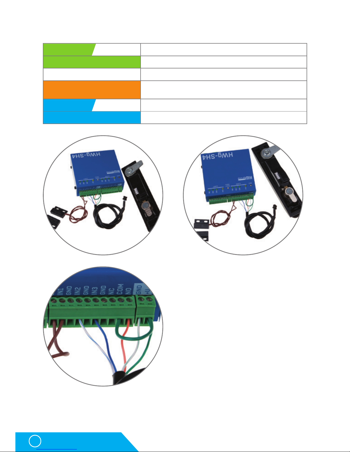
Southco HWg-SH1 + detail of connection
green white
Power GND = Power Out GND pin
green
Power +12V = Power Out +U pin
x
Not used
orange
Control Signal to Rele NO pin - Rele COM connect to Power
Out +U pin
blue white
Lock status to IN2 pin
blue
Mech status to IN3 pin
Page 45

HWg-SH4
45
Restoring the default settings
Restoring the default settings
The following steps will restore the factory default settings of the device
(also erases all passwords):
1. Turn the device off by disconnecting the power supply
2. Swith the DIP1 ON
3. Turn the device on (switch the power supply)
4. Wait approximately 15 seconds
5. Turn off the power supply
6. Turn the DIP1 OFF
7. Turn the power supply back on
Page 46

Notes
Page 47

Page 48

HW group s.r.o
Rumunská 26/122
Praque 2, 120 00
Czech republic
Tel.+420 222 511 918
Fax.+420 222 513833
www.HW-group.com
 Loading...