

Page 1
HWg-PWR
MANUAL
Page 2

HWg-PWR: M-Bus IP energy meter (SNMP, WEB)
HW group
www.HW-group.com
page 2
Package contents
A complete shipment contains the following items:
HWg-PWR unit
Printed manual + datasheet
Safety information
The device complies with regulations and industrial standards in force in the Czech Republic and
the European Union. The device has been tested and is supplied in working order. To keep the
device in this condition, it is necessary to adhere to the following safety and maintenance
instructions.
HWg-PWR connects directly to a 230VAC supply; therefore, it should be installed by
qualified personnel only!
Using the device in a manner other than prescribed by the manufacturer may cause its
safeguards to fail!
The power supply outlet or disconnection point must be freely accessible.
The device must not be used under any of the following conditions:
The device is noticeably damaged
The device does not function properly
Unfastened parts can move inside the device
The device has been exposed to moisture or rain
The device has been serviced by unauthorized personnel
The power adapter or power supply cable are noticeably damaged
If the device is used in a manner other than designed for, the protection provided by
the device may fail.
The electrical system must include a power switch or a circuit breaker and
overcurrent protection.
If you have any problems with installing or operating the device, you may contact
technical support:
HW group s.r.o.
http://www.hw-group.com
Email: support@HWg.cz
U Pily 3
143 00 Praha 4
Tel. +420 222 511 918
When contacting technical support, please note the exact type of your device (at the type
plate) and, if possible, the firmware version.
Page 3

HWg-PWR: M-Bus IP energy meter (SNMP, WEB)
HW group
www.HW-group.com
page 3
Table of Contents
Package contents ............................................................................................................... 2
Safety information ............................................................................................................. 2
Table of Contents .............................................................................................................. 3
What is HWg-PWR ............................................................................................................. 4
Usage examples ............................................................................................................. 4
Basic HWg-PWR features .................................................................................................. 5
Description of connectors and connections ...................................................................... 6
LED indicators ................................................................................................................ 6
Restoring factory defaults ............................................................................................. 6
Connecting meters to HWg-PWR .................................................................................. 7
Technical specifications ..................................................................................................... 8
First steps .......................................................................................................................... 9
1) Connecting the cables ............................................................................................... 9
2) Configuring the IP address – UDP Config .................................................................. 9
3) WWW interface of the device ................................................................................. 10
Adding connected meters and their variables ................................................................ 11
Automatic discovery of meters: .................................................................................. 12
Adding discovered meters to HWg-PWR..................................................................... 14
WWW interface ............................................................................................................... 16
Home tab ..................................................................................................................... 16
Graph tab ..................................................................................................................... 17
General Setup tab ........................................................................................................ 18
SNMP tab ..................................................................................................................... 20
E-mail tab ..................................................................................................................... 21
Time tab ....................................................................................................................... 22
Device tab .................................................................................................................... 23
Services tab.................................................................................................................. 26
System tab ................................................................................................................... 27
Mechanical .................................................................................................................. 28
Accessories ...................................................................................................................... 32
Manufacturer .................................................................................................................. 32
Page 4
HWg-PWR: M-Bus IP energy meter (SNMP, WEB)
HW group
www.HW-group.com
page 4
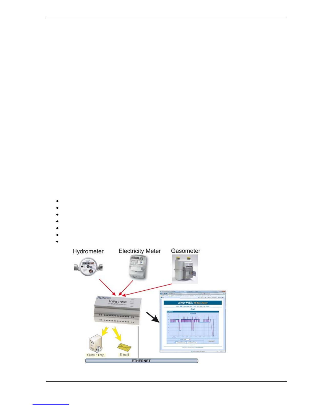
What is HWg-PWR
HWg-PWR is an Ethernet-enabled device for remote monitoring and metering of
electricity, heat, water or gas consumption using electricity, water, gas, heat, or other
meters equipped with the M-Bus interface. In addition to metering, the device also
supports alarming through e-mail or SNMP traps whenever allowed values are exceeded.
HWg-PWR is designed for remote reading of values from meters equipped with the M-Bus
interface. Each meter can provide multiple variables, depending on the meter type and
model. Typically, electricity meters provide the total electricity consumption and also the
immediate value at the time of reading, line voltage and/or line current; water meters
indicate total water consumption as well as immediate consumption or liquid flow rate;
and so on.
Note: HWg-PWR is designed to be universal; hence, all discovered values are read out
from every connected meter, until a specified limit is reached. To improve user comfort, it
is possible to enable or disable each discovered value (disabled value is hidden from view),
and to turn on or off the recording of measured readings for each enabled value (in order
to increase the available recording time for the remaining values).
The M-Bus protocol allows to read value names, units, or tariff information from the
meters. The user can customize all of these data (e.g. change the unit of measurement or
its multiplier).
Usage examples
Remote monitoring of electricity meters in small server rooms and BTS
Monitoring of energy consumption in rented premises
Reading out energy consumption in remote or inaccessible areas
Control over energy costs
Checking for individual line overloads in three-phase wirings
Checking for undervoltage in electric wirings
Monitoring the flow of liquids
Page 5
HWg-PWR: M-Bus IP energy meter (SNMP, WEB)
HW group
www.HW-group.com
page 5
Basic HWg-PWR features
Ethernet: RJ45 (10BASE-T)
WEB: Embedded WEB server / GUI
Works with up to three M-BUS meters (electricity, gas, …)
Unlimited number of measured variables*
o Instantaneous power input
o Total consumption
o Line voltage
o Line current
o Flow speed
o etc.
Works with up to 30 values (this limit is independent from the
number of meters)
Automatic detection of meters and supported values
Support for certified and calibrated meters
Support for single-phase and polyphase electricity meters
Support for single-tariff and multi-tariff meters
Logging of measured values with the option to plot graphs
Configuration of allowed ranges for measured values
Independent counters for periodic consumption readouts (daily, weekly, monthly,
annually, ...)
Configuration of the unit of measurement and its exponent
Periodic e-mailing of measured values over HTTP and by e-mail
DIN rail mount with a power supply for M-BUS
M2M communication protocols: SNMP, XML, Modbus/TCP
Response to thresholds: SNMP trap, Email
Support for programmers: HWg SDK
Supported software
o HWg-PD Trigger: Control of other IP devices, alert redirection to SMS
o HWg-PDMS: Logging, export to MS Excel
o Third-party SNMP software
(HP OpenView, IBM Tivoli, Nagios, Zabbix, Monitor one, The Dude, Paessler IPCheck, Ipswitch
WhatsUp, Axence nVision, CBR little:eye, LoriotPro, GFi NSM, SNMPc 7, CA NSM, ActiveXperts NM,
Intellipool NM, MSC Operations Manager 2007)
* Displayed variables depend on the actual meter
Page 6
HWg-PWR: M-Bus IP energy meter (SNMP, WEB)
HW group
www.HW-group.com
page 6
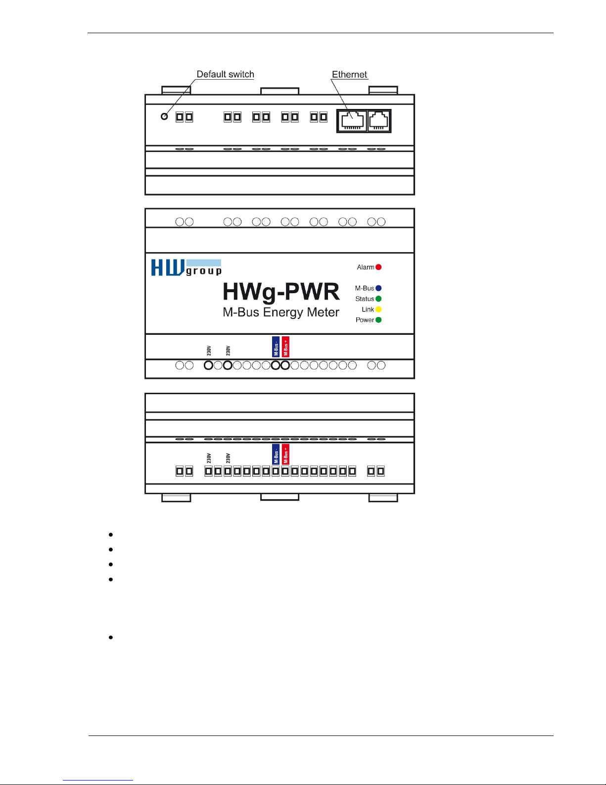
Description of connectors and connections
LED indicators
Power (green) – lights up when the device is powered.
Alarm (red) – lights up whenever a monitored variable is in alarm.
M-Bus (blue) – flashes whenever M-Bus communication takes place.
Status (green) – HWg-PWR status
o Solid on – HWg-PWR is in regular operation
o Slowly flashing – HWg-PWR is starting up
o Rapid flashing – firmware is being uploaded
Link (amber) – flashing indicates activity on the Ethernet interface.
Restoring factory defaults
Press and hold the Default Switch button, connect power, and hold the button pressed for
10 more seconds. HWg-PWR resets itself to factory defaults. Be careful when working
with HWg-PWR in a distribution box.
Page 7
HWg-PWR: M-Bus IP energy meter (SNMP, WEB)
HW group
www.HW-group.com
page 7
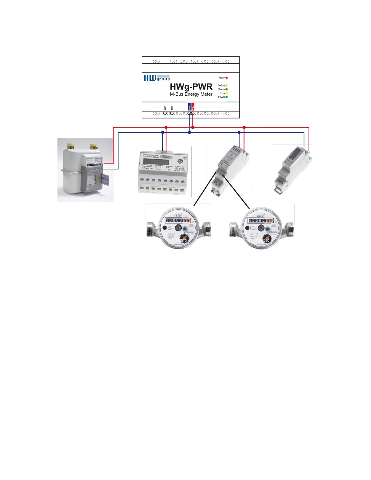
Connecting meters to HWg-PWR
Page 8
HWg-PWR: M-Bus IP energy meter (SNMP, WEB)
HW group
www.HW-group.com
page 8
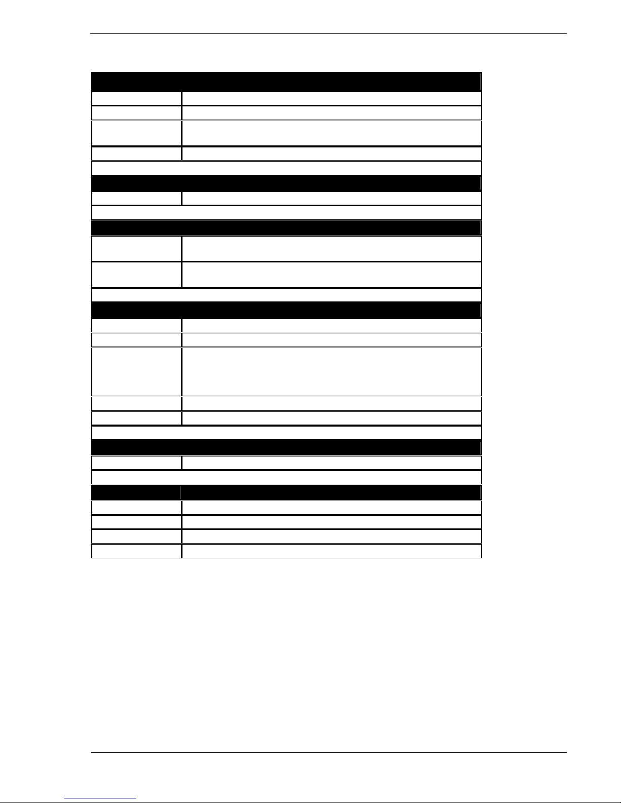
Technical specifications
Ethernet port
+ Interface
RJ45 (10BASE-T / 100BASE-Tx)
+ Compatibility
Ethernet: Version 2.0/IEEE 802.3
+ Supported
protocols
IP: ARP, TCP/IP (HTTP, SMTP), UDP/IP (SNMP, SNMP Traps, DHCP, SNTP)
+ SNMP
Ver:1.00 compatible, partial ver. 2.0 implementation
M-Bus
+ Bus rating
30-40V / max. 40mA
Environment
+ Operating / storage
temperature
-5 to +50 °C (+23 to +122 °F) / -5 to +75 °C (+23 to +167 °F)
+ Relative humidity
(non-condensing)
5 to 95 %
LED indicators
+ POWER (green)
lights up when the device is powered
+ LINK (red)
flashes whenever communication takes place over the Ethernet interface
+ Status (red)
HWg-PWR status:
- Solid on – HWg-PWR is in regular operation
- Slowly flashing – HWg-PWR is starting up
- Rapidly flashing – firmware is being uploaded
+ Alarm (red)
lights up whenever a monitored variable is in alarm
+ M-Bus (amber)
flashes whenever communication takes place over M-Bus
Buttons
+ Default switch
When depressed at power up, resets the device to factory defaults
Miscellaneous
+ Supply voltage
230 V/ 10VA; terminal block
+ Dimensions
143 x 90 x 57 [mm]
+ Fixing
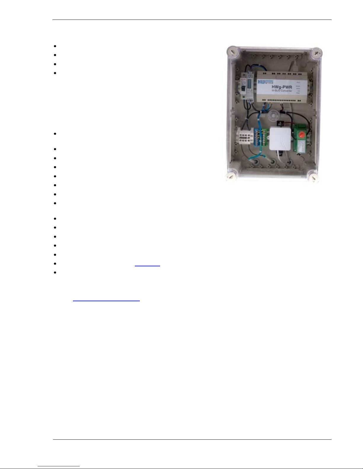
DIN rail; device is intended for installation into a distribution box
+ Mass
390 g
Page 9
HWg-PWR: M-Bus IP energy meter (SNMP, WEB)
HW group
www.HW-group.com
page 9
First steps
1) Connecting the cables
HWg-PWR connects directly to a 230VAC supply; therefore, it should be installed by
qualified personnel only!
Connect the unit to the Ethernet (a patch cable to a switch, or a cross-over
cable to a PC).
Connect the M-Bus with meters. Pay attention to the polarity!
Connect HWg-PWR to the electrical network.
The green Power LED lights up.
If the Ethernet connection works properly, the LINK (amber) LED lights up after
a short while, and then flashes whenever data transfer takes place (activity
indication).
After power up, the amber LINK LED flashes rapidly to indicate IP address
negotiation over DHCP.
The green M-Bus LED indicates communication over the M-Bus.
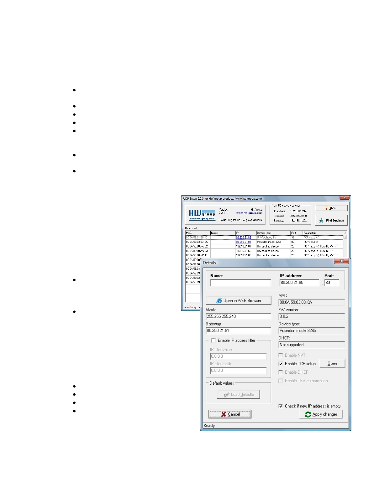
2) Configuring the IP address – UDP
Config
UDP Config utility – root directory of the
supplied CD (Windows and Linux versions).
Available for download at www.HW-
group.com, Software > UDP Config.
Click the icon to launch UDP
Config. The program
automatically looks for connected
devices.
To search for devices, click the
Find Devices icon.
The program searches for devices on your local
network. Double-click a MAC address to open a
basic device configuration dialog.
Configure the network parameters
IP address / HTTP port (80 by default)
Network mask
Gateway IP address for your network
Device name (optional)
Click the Apply Changes button to save the
settings.
Page 10
HWg-PWR: M-Bus IP energy meter (SNMP, WEB)
HW group
www.HW-group.com
page 10
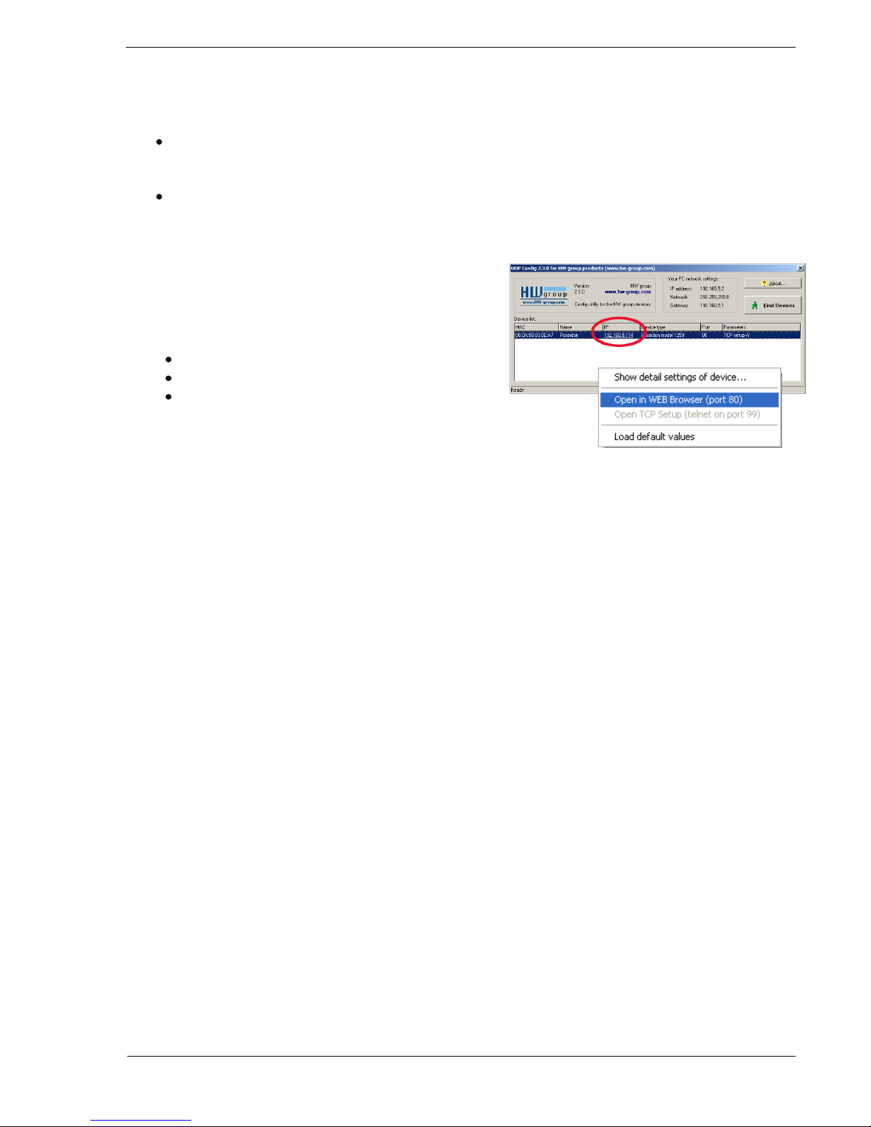
Restoring factory defaults
Right-click a device MAC address. Within 60 seconds after powering up the unit,
factory defaults can be restored using UDP Config.
Disconnect the power jack, connect the jumper near the RJ11 sockets, power up
the device and wait for 15 seconds. Then, disconnect the power and disconnect
the jumper. The device is ready in its factory default configuration.
3) WWW interface of the device
To open the WWW interface of the device:
Enter the IP address into a web browser
Click the IP address in UDP Config
Click the underlined IP address in UDP SETUP
Page 11

HWg-PWR: M-Bus IP energy meter (SNMP, WEB)
HW group
www.HW-group.com
page 11
Adding connected meters and measured values
Start the WWW interface of HWg-PWR and go to the Device menu. The list of detected
meters is empty. Individual meters are always added to HWg-PWR manually. A tool for
automatic discovery of meter addresses is also available in the Mbus Scan submenu (only
finds meter addresses, does not add them to the system):
Page 12

HWg-PWR: M-Bus IP energy meter (SNMP, WEB)
HW group
www.HW-group.com
page 12
Automatic discovery of meters:
1. At the Device Base Parameters page, fill in the M-Bus Scan section:
- Address – Range of M-Bus addresses where the meters can be discovered.
The default is 0-252; however, a smaller range can speed up the discovery
process significantly.
- Serial Baudrate – Communication speed. The default is 2400 but this can
differ for various meters – see the meter documentation.
- Serial Parity – Communication parity. The default is Even but this can
differ for various meters – see the meter documentation.
2. Click Scan.
3. The M-Bus Device Scan Status section displays the discovery progress (Actual scan
state) and discovered meters (Found Device).
4. After the scan is complete, Actual scan state changes to Stopped.
Page 13

HWg-PWR: M-Bus IP energy meter (SNMP, WEB)
HW group
www.HW-group.com
page 13
5. Write down the addresses of discovered devices and return to the Device page.
Note: If HWg-PWR does not find any connected meters, re-check the M-Bus connection (in
particular its polarity) and the baudrate and parity configuration, or try to look up these
values in the documentation of your meter. Repeat the search until you find all meters.
When only some of the meters are found but not all, the problem may be in different
communication parameters. Repeat the search with other Serial Baudrate and Serial Parity
settings.
Page 14

HWg-PWR: M-Bus IP energy meter (SNMP, WEB)
HW group
www.HW-group.com
page 14
Adding discovered meters to HWg-PWR
1. In the Device menu, select the desired meter. The Edit xMeter section displays.
2. In the Address M-Bus field, fill in the address discovered by scan or written on the
meter or in the meter documentation. Set the Serial Baudrate and Serial Parity
parameters – see the meter or its documentation.
3. Turn on the meter in the system (change Enable to Enable).
4. Click Save to save your changes.
5. The Secondary Address, Medium and Manufacturer fields are read out
automatically and displayed when the page is refreshed.
6. Now select the Scan Value submenu of the corresponding meter (from the menu).
Page 15
HWg-PWR: M-Bus IP energy meter (SNMP, WEB)
HW group
www.HW-group.com
page 15
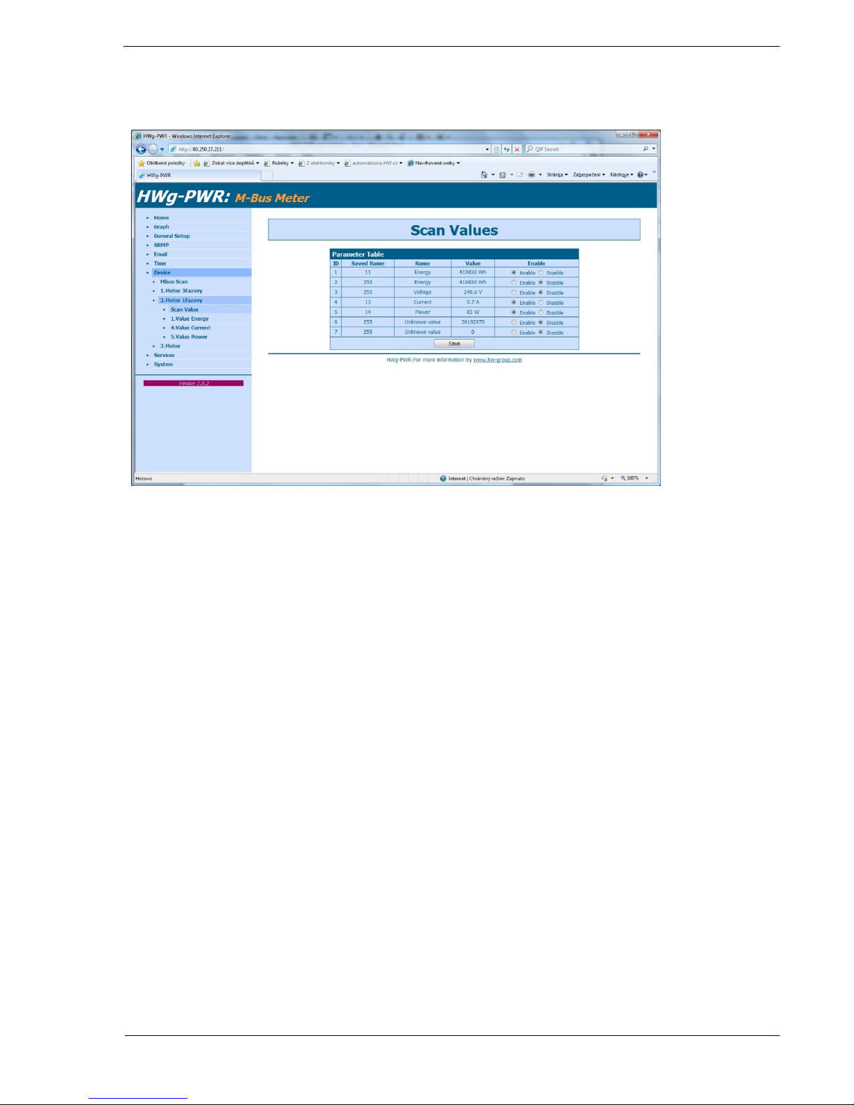
7. A list of values provided by the meter is displayed. Individual values can be turned
on (Enable) and off (Disable):
8. Click Save to save your changes.
Important: In order to find meter variables, the meter must be enabled and saved. It is not
possible to scan values without saving the meter configuration first!
Repeat steps 1 to 3 to add all required meters.
Page 16

HWg-PWR: M-Bus IP energy meter (SNMP, WEB)
HW group
www.HW-group.com
page 16
WWW interface
Home tab
The Home tab displays current readouts of all enabled values of a meter, together with
status symbols.
The value is within its allowed range (Saferange)
The value is out of its allowed range (Saferange)
M-Bus communication error – meter stopped responding
Page 17

HWg-PWR: M-Bus IP energy meter (SNMP, WEB)
HW group
www.HW-group.com
page 17
Graph tab
The Graph tab lets you plot a graph of the measured values. To plot a graph, you need to
specify:
Source Value – List of all variables with enabled logging in the Meter-name.value
format.
Interval – Time interval to be plotted. You can select one of the pre-defined
intervals (Hour, Day, Week, Month, Year), or manually fill in the start date (From)
and the end date (To). If you select an interval for which there is no valid data, the
graph will be empty.
After selecting the parameters, click Show Graph to generate the graph. This operation
may take some time, depending on the number of measured values.
Page 18

HWg-PWR: M-Bus IP energy meter (SNMP, WEB)
HW group
www.HW-group.com
page 18
General Setup tab
The General Setup tab is used to configure basic operating parameters of HWg-PWR.
Base section
Device Name – Custom name of the HWg-PWR device in order to distinguish
multiple HWg-PWR units in a network. The device name can be up to 16
characters long.
WWW Info Text – Custom text in the WWW interface footer. Useful for contact
information about the operator of that particular HWg-PWR, if the device is
accessible on a public IP.
Periodic restart – Enables periodic restart of HWg-PWR to prevent problems in
noisy Ethernet networks or to limit the consequences of hacker attacks.
Network section
DHCP – Enables IP address assignment by a DHCP server, if available. Ask your
network administrator if unsure about the correct setting.
IP Address – IP address of HWg-PWR. Assigned by your network administrator.
Network Mask – Network mask. Assigned by your network administrator.
Gateway – IP address of the default gateway. Assigned by your network
administrator.
Page 19

HWg-PWR: M-Bus IP energy meter (SNMP, WEB)
HW group
www.HW-group.com
page 19
DNS Primary / DNS Secondary– IP address of your DNS server. Assigned by your
network administrator.
HTTP Port – Port number where the built-in WWW server listens. Changing the
port number is useful in situations where multiple HWg-PWR units need to be
accessible from an external network through a router. Ask your network
administrator if or whether you need to change this value. The default port is 80.
SysLog IP Address – IP address of a syslog server. Syslog servers help troubleshoot
problems with Ethernet devices.
Security: Device Admin section
Username / Password – User name and password for securing access to HWg-
PWR.
Page 20

HWg-PWR: M-Bus IP energy meter (SNMP, WEB)
HW group
www.HW-group.com
page 20
SNMP tab
The SNMP tab is used to configure SNMP communication parameters and target
destinations for SNMP Trap alarms.
General SNMP Settings section
System Name – Name of HWg-PWR within SNMP.
System Location – Location of HWg-PWR within SNMP.
System Contact – Contact information of the HWg-PWR administrator within
SNMP.
SNMP port – Port number for SNMP communication. The default is 161.
SNMP Access section
Community – Name of the SNMP community for accessing HWg-PWR over SNMP.
Two communities can be defined. Each Community can have the following
permissions defined:
o Read
o Write
SNMP Trap Destination section
Destination – Index of the target destination for SNMP traps. Only A can be set,
other indexes are reserved for future use.
Community – Name of the Community where the SNMP trap is sent.
IP Address – Target IP address for SNMP Traps.
Port – Target port for SNMP Traps. Default is 162.
Enable – Activation of the target destination. Useful for disabling all SNMP traps
without regard to the settings for individual values.
Page 21

HWg-PWR: M-Bus IP energy meter (SNMP, WEB)
HW group
www.HW-group.com
page 21
E-mail tab
The E-mail tab is used to define the e-mail server and the parameters for sending alarm emails (beginning or end of an alarm). HWg-PWR only supports unencrypted SMTP
connections.
Email Settings section
SMTP Server – IP address or domain name of your SMTP server.
SMTP port – Port number where the SMTP server listens. The default is 25.
Authentication – Enables authentication. Check this box if your SMTP server
requires authentication.
Username – Username for authentication to the SMTP server. If the
Authentication box is not checked, this field is irrelevant.
Password – Password for authentication to the SMTP server. If the Authentication
box is not checked, this field is irrelevant.
FROM – E-mail address of the sender, that is, the HWg-PWR unit. The address
may be necessary for the SMTP server and it can be used to identify the HWgPWR unit, or for filtering and further processing of alarm messages.
Subject – E-mail subject. Contents of this field can be used to identify the HWg-
PWR unit, or for filtering and further processing of alarm messages.
TO – E-mail address of the recipient of alarm messages. Only one e-mail address
can be entered.
Page 22

HWg-PWR: M-Bus IP energy meter (SNMP, WEB)
HW group
www.HW-group.com
page 22
CC – E-mail address of the recipient of a copy of the alarm message. Only one e-
mail address can be entered.
The To and CC fields cannot accept distribution lists or multiple e-mail addresses. If
you need to send alarm messages to more recipients, ask your SMTP server
administrator to create a distribution list accessible through a single e-mail address.
Send Test Email section
After configuring Email Settings, use this button to send a test e-mail.
Time tab
The Time tab is used to configure system time and automatic synchronization with a
timeserver.
SNTP Setup section
SNTP Server – IP address or host name of the time synchronization server. Default
is time.nist.gov.
Time Zone – Timezone where HWg-PWR is located. Used to set correct system
time. Necessary for correct logging of measured values.
Summertime – Enables daylight savings time. Used to set correct system time.
Necessary for correct logging of measured values.
Interval – The period for synchronizing time with the server.
SNTP Synchronize section
The Sync button immediately synchronizes time with the time server. Can be used to test
the settings.
Time Setup section
The Time Setup section lets you enter current date and time manually, when
synchronization with a time server is unavailable.
Page 23

HWg-PWR: M-Bus IP energy meter (SNMP, WEB)
HW group
www.HW-group.com
page 23
Device tab
This tab is used to discover connected meters (Device), set their parameters, and to
subsequently find and configure the values provided by individual meters.
Device List section
The Device List section lists all connected meters together with their type (Medium) and
address (Address) on the M-Bus. To edit a meter, click “Edit” on the corresponding line.
Each meter is assigned a unique ID within HWG-PWR for use in XML and SNMP
communication.
Edit xMeter section
Page 24

HWg-PWR: M-Bus IP energy meter (SNMP, WEB)
HW group
www.HW-group.com
page 24
Secondary Address – Secondary address on the M-Bus. This address is used to
identify a meter if there are more meters with the same primary address (Address
field) on the bus. Secondary Address is non-editable and consists of a
manufacturer-defined part and the Address field (last 2 characters).
Medium – Type of the meter (electricity, gas …). The medium is not editable.
Enable – Enables or disables the meter within HWg-PWR. When a meter is
disabled, values are not detected or read but the configured parameters remain
stored. This can be used to temporarily turn off the reading and recording for a
meter (during maintenance etc.)
Address – Primary address on the M-Bus. The address is entered as one byte
(0-255).
Serial Baudrate – M-Bus communication speed for the particular meter. By
default, 2400 Baud is configured. Meters with different communication speeds
can coexist on a single bus; this parameter sets the speed for a particular meter.
Serial Parity – M-Bus communication parity. As with the baudrate, parity can be
specified individually for each meter.
Name – Meter name. Identifies the meter within HWg-PWR – in graphs, XML and
SNMP.
Scan Value – Reads out the values and their parameters from the meter. See First
Steps.
Parameter Table section
The Parameter Table section displays information about discovered values from a
particular meter – their names (Name), units of measurement (Unit) and current readings
(Value). Each value is assigned a unique ID within HWG-PWR for use in XML and SNMP
communication. To edit a value, its parameters and properties, click “Edit” on the
corresponding line.
Page 25

HWg-PWR: M-Bus IP energy meter (SNMP, WEB)
HW group
www.HW-group.com
page 25
Edit y.Value on x.Meter section
Name – Value name. Identifies the value (variable).
Unit – Physical unit of measurement. Identifies the unit of the value being
measured. Together with its exponent, it can be used to convert the value to a
custom format and unit (W/kW, kWh/MWh, dm3/l and so on).
Exponent – Allows you to change the order of the displayed unit of measurement.
Tarif – Identifies the tariff in multi-tariff meters.
Zero Offset – Bias. Allows a modification of the displayed value by adding
(subtracting) a fixed number. Typically used to monitor differences for a given
time period.
Logging Enabled – Enables the recording of readouts into the internal memory.
Recording interval is specified at the Log tab. When logging is enabled for fewer
variables, more records can be stored.
Value Alarming – Enables alarming for the current value. This is useful for making
sure that a value (line current, flow rate etc.) stays within its allowed range. This
function can inform you about overconsumption or suspiciously low consumption
and help avoid further problems.
SafeRange Hi – High limit. Alarm occurs if the measured value exceeds the value
specified here.
SafeRange Lo – Low limit. Alarm occurs if the measured value falls below the
value specified here.
Saferange Hyst – Allowed hysteresis. Suppresses false alarms if the measured
value oscillates near the threshold. The hysteresis only applies in the direction
Page 26

HWg-PWR: M-Bus IP energy meter (SNMP, WEB)
HW group
www.HW-group.com
page 26
into the SafeRange. That is, alarm always starts when SafeRange Hi or SafeRange
Lo is crossed but only ends when the threshold plus (or minus) Saferange Hyst is
reached.
E-Mail if Change State – Specifies whether an e-mail should be sent whenever an
Alarm begins or ends.
SNMP Trap if change state – Specifies whether a SNMP Trap should be send
whenever an Alarm begins or ends.
Services tab
The Services tab lets you specify the period for storing readouts. The number of recorded
values and logging period determine the lifespan of the records. The shorter the period,
the sooner the memory fills up.
Page 27

HWg-PWR: M-Bus IP energy meter (SNMP, WEB)
HW group
www.HW-group.com
page 27
System tab
The System tab is used to access the most important system information, such as uptime
or firmware version, and to perform operations such as HWg-PWR restart or firmware
update.
Download section
Backup configuration – Click to save the current HWg-PWR configuration. Saved
configuration can be later restored. (http://hwg-pwr.hwg.cz/HWg-
PWR_Config.bin)
Online values in XML – Address of a XML file with current readouts. Intended for
automated processing at remote servers. (http://hwg-pwr.hwg.cz/values.xml)
SNMP MIB Table – Address of the MIB file that contains the definitions of SNMP
variables. (http://hwg-pwr.hwg.cz/HWg-PWR.mib)
TXT list of common SNMP OIDs – Overview of the most important OIDs from the
MIB table. (http://hwg-pwr.hwg.cz/HWg-PWR_OID.txt)
Data Log CSV Format – Address of a CSV file with a logged history of readouts.
Intended for automated processing at remote servers. (http://hwg-
pwr.hwg.cz/log.csv)
Page 28

HWg-PWR: M-Bus IP energy meter (SNMP, WEB)
HW group
www.HW-group.com
page 28
Mechanical
Page 29

HWg-PWR: M-Bus IP energy meter (SNMP, WEB)
HW group
www.HW-group.com
page 29
Page 30

HWg-PWR: M-Bus IP energy meter (SNMP, WEB)
HW group
www.HW-group.com
page 30
Page 31

HWg-PWR: M-Bus IP energy meter (SNMP, WEB)
HW group
www.HW-group.com
page 31
Page 32

HWg-PWR: M-Bus IP energy meter (SNMP, WEB)
HW group
www.HW-group.com
page 32
Accessories
DHZ 5/63-M-BUS
Single-phase 63A electricity meter with M-Bus
ED 310.DB HWG
Three-phase, two-tariff, 63A electricity meter with M-Bus
and S0
M-Count 2C
Converter and datalogger, 2x pulse output (S0) / M-Bus
Manufacturer
HW group s.r.o
Rumunská 26 / 122
Praha 2, 120 00
Tel. +420 222 511 918
Fax. +420 222 513 833
http://www.HW-group.com
DHZ 5/63-M-BUS
ED 310.DB HWG
M-Count 2C
 Loading...