

HWAM Figaro, Vivaldi, Monet, Mozart, Hwam 30 Installation, Commissioning And Maintenance Instructions
...Page 1

E & OE Instructions Part number IN1140 Ed A
1
© EUROHEAT DISTRIBUTORS (H.B.S) LTD. Nov 2006
IN1140
Installation, Commissioning and
Maintenance Instructions
Figaro
Vivaldi
Monet
Mozart
Hwam 30
Hwam 60
Beethoven
Ravel
Dali
Wood Models
This Manual Must Always Be Available To The Stove Operator
Serial Number
Part No.
Model Name
This manual must be used in conjunction with document
IN1173 The Wood and Mutlifuel Chimney and Installation Guide,
Page 2
© EUROHEAT DISTRIBUTORS (H.B.S) LTD. Nov 2006
E & OE Instructions Part number IN1140 Ed A
2
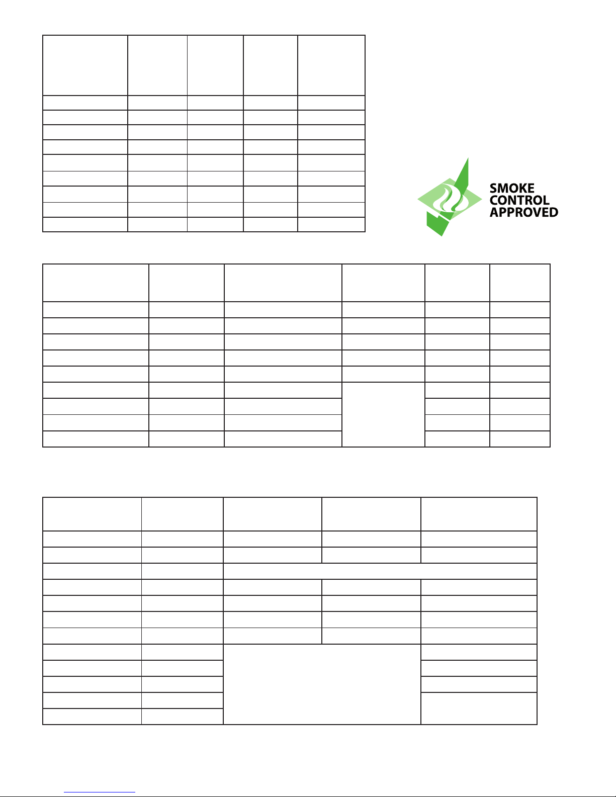
Model Flue Size Air Requirement
Equivalent Area as
Approved Document J
UK Smoke Control
Exemption
Efficiency Net %Efficiency
Gross %
Vivaldi 6” (153mm) Nil Yes* 77 70.5
Beethoven 6” (153mm) Nil
Yes* 77 70.5
Mozart 6” (153mm) Nil
Yes* 77 70.5
Ravel 6” (153mm) Nil
yes* 77 70.5
Hwam 30 6” (153mm) Nil
Yes* 77 70.5
Monet 6” (153mm) 385mm
2 75 68.4
Figaro 6” (153mm) 551mm
2 73 67
Hwam 60 6” (153mm) 385mm
2 75 68.4
Dali 6” (153mm) 385mm
2 75 68.4
Technical Details
Model Name Heat Output
Nominal
Wood
Flue
Draught
Nominal
Heat
Output
Flue Gas
Mass Flow
g/s
Flue Gas
Temperature
deg C
Vivaldi 3.5kW 12pa 4.6 272
Beethoven 5.9kW 12pa 4.6 272
Mozart 7.9kW 12pa 4.6 272
Ravel 10.5 12pa 4.6 272
Hwam 30 3.5kW 12pa 4.6 272
Monet 5.7kW 13pa 6.2 267
Figaro 6kW 12pa 7.49 291
Hwam 60 5.7Kw 13pa 6.2 267
Dali 5.7kW 13pa 6.2 267
* The Hwam models Beethoven, Vivaldi, Mozart, Ravel and Hwam 30 are considered as exempt for use in smoke control areas if they
have been modified to ensure the air wash/secondary air control cannot be fully closed. If this modification has not been carried out
the appliance is not considered exempt under the Clean Air Act.
More information on alliance weight can be found in the hearths section of this manual.
Model Weight
Weight
with draw
Weight with
wood section
Weight with
Soapstone
Monet 150kg 150kg 147kg 245kg
Monet H 180kg 180kg 207kg 295kg
Monet with boiler 150kg
Mozart 88kg 88kg 85kg 111kg
Dali 151kg 156kg 151kg
Beethoven 95kg 114kg 95kg 160kg
Beethoven H 116kg 116kg 112kg 275kg incl. Draw
Vivaldi 78kg 93kg
Figaro 133kg
Ravel 108kg 108kg
Hwam30 87kg
Hwam 60 114kg
Page 3

E & OE Instructions Part number IN1140 Ed A
3
© EUROHEAT DISTRIBUTORS (H.B.S) LTD. Nov 2006
IMPORTANT
.
The installation of this appliance must comply with all local regulations, including those referring to
national and European Standards before it can be operated. The stove is not suitable for a shared flue.
However, for England and Wales, only, the coming into force on 1st April 2002 of SI 2002 No 440 exempts
the householder from this legal requirement for the installation of solid fuel fired appliance whose rated heat
output is 50kW or less in a building having no more than 3 storeys (excluding any basement) if a Competent
Engineer is employed who is registered under the Registration Scheme for Companies and Engineers involved
in the Installation and Maintenance of Domestic Solid Fuel Fired Equipment operated by HETAS Ltd. These
registered Competent Engineers may also carry out associated building work necessary to ensure that the
installed appliance complies with Building Regulations without involving the Local Authority Building Control
Department.
Improper adjustment, alteration, maintenance or the fitting of replacement parts not recommended by the
manufacturer can cause injury or property damage. Do not operate the stove with faulty seals or damaged
glass.
Due to the high operating temperatures of this appliance it should be located away from pedestrian traffic
and away from furniture and draperies. Do not store paper or wood near the appliance. Any mats and rugs put
in front of the stove should be fire proof and secured to prevent the possibility of tripping.
Advise all persons as to the stove’s high surface temperatures. If it is possible for children or infirm adults to
come into contact with the stove, fit a suitable fire guard.
It is imperative that all air passageways into, out of, and within the appliance are kept clean. All permanent
ventilation into the room provided for the stove must remain clear and unobstructed at all times. Consideration
must be given to the need for extra ventilation if another heating source needing air is to be operated
simultaneously. If an extraction fan is proposed to be fitted to a connecting area of the house, after the stove
has been installed, professional advice should be sought from a qualified engineer.
The user should be advised that the appliance should be inspected regularly and the chimney cleaned at
least annually.
More frequent cleaning may be required and the advice of a qualified chimney sweep should be sought.
Our range of stoves is capable of operating with outstanding efficiency if the flue system is correct. Because
so little heat is wasted to the flue it is possible that moisture within the products of combustion will condense
if the heat losses within the flue way are too great and allow the flue gases to cool. For this reason we
recommend that the stove is fitted with a suitable flue liner, the same diameter as the flue spigot, to prevent
the possibility of acidic damage to the fabric of the chimney and damage to the stove which will reduce the
longevity of the stove.
When correctly installed, the stove is designed to produce heat, safely. It cannot do so if the installation is
less than absolutely stable, constructed of materials suitable for such an installation and consideration has not
been given to the possibility of people with less than ideal common sense operating it.
Have the existing chimney swept by a chimney sweep. Although you will be lining the chimney, any deposits
left in the chimney will cause problems and may become a fire hazard.
Your attention is drawn to the precautions and responsibilities under the Health and Safety at Work Acts,
and whatever new legislation being introduced during the life of this document.
Page 4

© EUROHEAT DISTRIBUTORS (H.B.S) LTD. Nov 2006
E & OE Instructions Part number IN1140 Ed A
4
Euroheat Distributors (H.B.S). Ltd.
Unit 2,
Court Farm Business Park,
Bishops Frome,
Worcestershire. WR6 5AY.
www.euroheat.co.uk
[email protected]
Useful organisations
Solid Fuel Association 0845 601 4406 www.solidfuel.co.uk
The National Association of Chimney Sweeps 01785 811732 www.chimneyworks.co.uk
HETAS Ltd. 0845 634 5626 www.hetas.co.uk
The Model Range Explained
Thank you for purchasing your stove and helping to protect our environment. Hwam and Euroheat insist on
progressive development to produce products which are market leading. Our aims are to produce stoves with
the latest innovations, user friendly operation and high efficiency for lower cost operation.
This operation manual offers user information for the range of Figaro, Vivaldi, Monet, Mozart, Hwam 30, Hwam
60, Beethoven, Ravel and Dali.
Model Identification
You will see on the front page of this document a label which confirms which model you have. This label also
advises you of the stoves unique serial number. This information is also attached to your stove for reference.
Important
Please ensure the warranty registration form is returned to Euroheat. In this way the model and its history will
be recorded for reference in the future.
Whilst we are always happy to assist you, please make sure you have read this manual before contacting
the technical support team.
Technical support Telephone Number 01885 491117. E-mail [email protected]
Before Operating this Appliance
The paint used on the stove is a heat resistant paint capable of withstanding 650°C, but it needs to be heated
for several hours to allow it to cure and attain its full hardness. The lighting procedure should be followed and
the stove’s first fire limited to a small fire for one hour, after which its size can be gradually increased to allow
the stove to reach its operating temperature. As the temperature of the paint increases a blue hazy smoke will
be apparent as the solvents in the paint are driven out. These fumes may activate a smoke detector, if fitted,
and during this period the room must be ventilated by leaving the windows open and it should not be occupied
by people or pets. The time taken for the paint to be fully cured will be dependant upon the temperature but
you should allow at least six hours. If you re-paint or fit new parts to your stove, another period of curing will
be necessary but the curing time will be very much shorter.
Hwam
Nydamsvej 53 Dk -8362 Horning Denmark
www.hwam.com
Page 5
E & OE Instructions Part number IN1140 Ed A
5
© EUROHEAT DISTRIBUTORS (H.B.S) LTD. Nov 2006
Grate Cover Plate
Your HWAM stove is supplied with a loose cover plate for the riddling grate. This is a 3 mm thick steel plate. It
is placed on top of the riddling grate and prevents the embers from falling into the ash pan. The cover plate is
raised approx. 8 mm above the grate, thus ensuring that the automatically controlled primary combustion air is
distributed evenly at the base of the combustion chamber.
Stoves Construction
Before the stove is installed, you must ensure that all the component parts are fitted correctly. See the verticalcross sections of the stoves page 8 onwards.
IMPORTANT:- Transport Security Tags
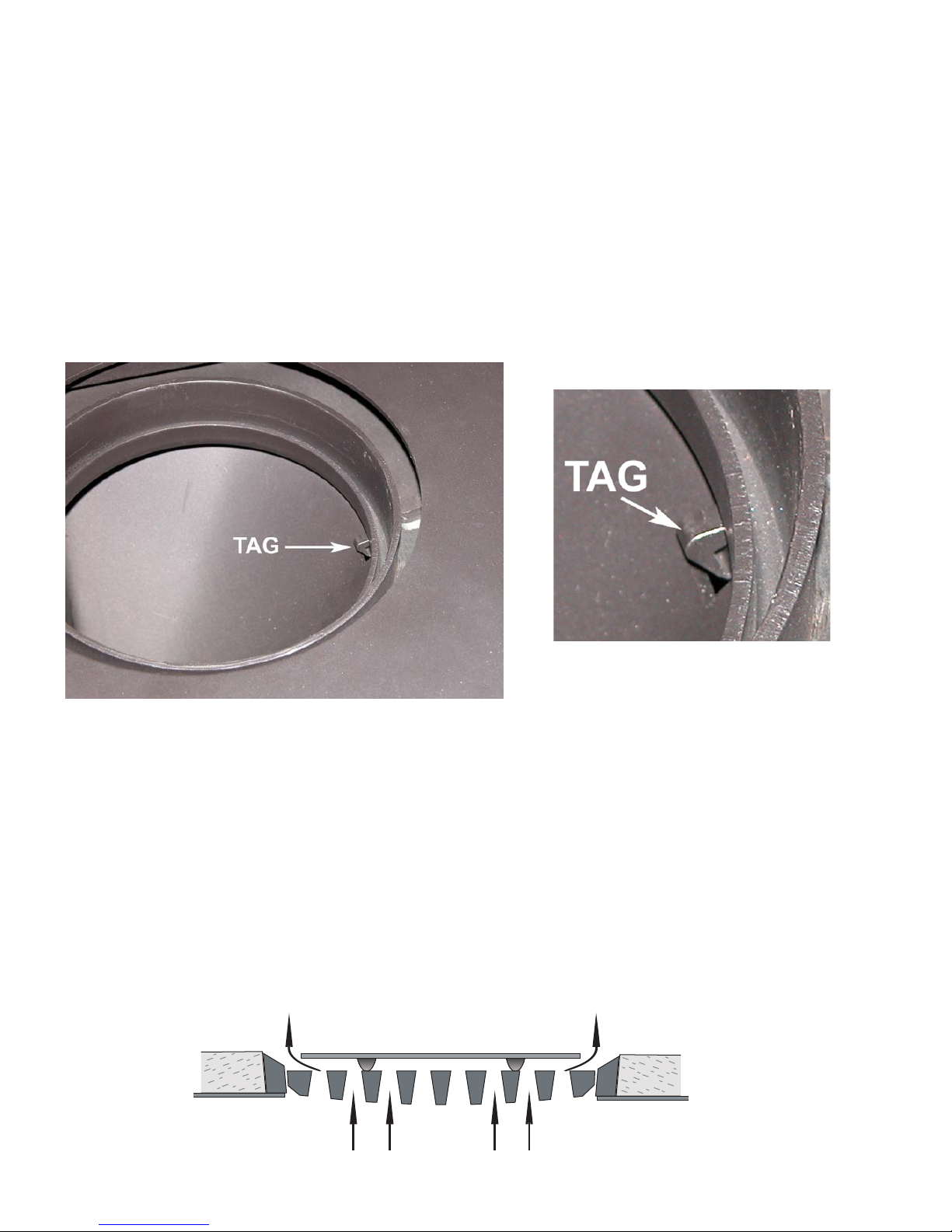
Beethoven, Monet, Mozart, Ravel, Vivaldi, Hwam 30 and Hwam 60
These models have a security tag to prevent damage to the stove by the baffle plate in transit. The baffle plate
is hung on three hooks under the top plate. The front middle hook has an extra bent tag as transport security
which should be removed before the stove is fitted. This must be removed to allow baffle removal for access
for sweeping and cleaning.
Removal before the stove is installed
The tag is visible as you look down through the flue spigot. It should be carefully snapped off by either using
pliers or a punch and a hammer.
The security tag should be removed before installation, however it is possible with some difficulty to remove
after installation. Take out the mica board baffle from the rear of the firebox. The security tag can be seen up at
the top of the inside of the fire box. To remove it a sharp blow with a hammer will break it off. The mica board
baffle should then be replaced.
Page 6
© EUROHEAT DISTRIBUTORS (H.B.S) LTD. Nov 2006
E & OE Instructions Part number IN1140 Ed A
6
Top to Rear Flue Conversion
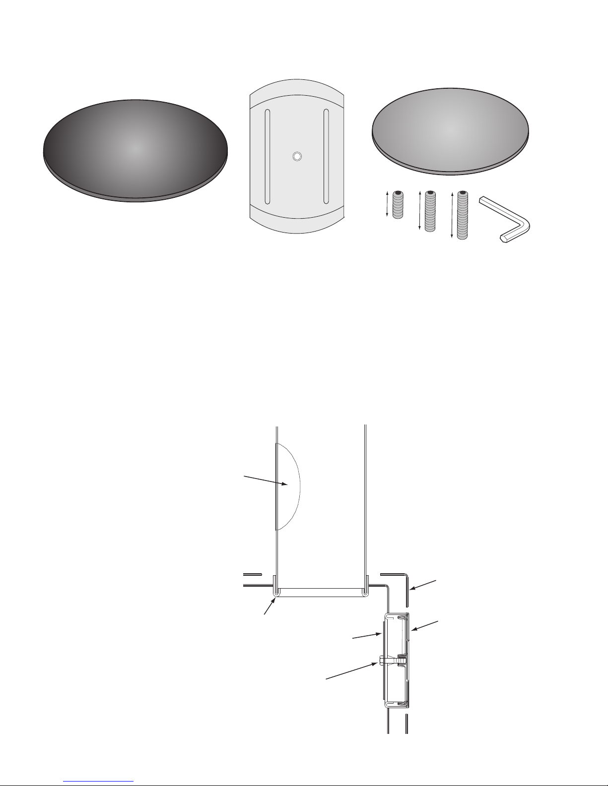
Top Flue Blanking Kit (Part No. AC004 for black nish, AC005 for grey nish)
20mm
25mm
35mm
Inner Blanking Plate
Outer Blanking Plate
Middle Securing Plate
Removal of the Rear Outlet Blanking Plate
1) Take off the rear back panel of the stove.
2) Take out the back vermicultie fire plate, to expose the nut on the inside of the rear blanking plate.
3) Remove all the components of the rear blanking plate, see diagram below.
4) Replace the rear heat shield.
5) A Tee piece adapter (part No. AC006) may be required when using a Tee pipe from the rear of the stove.
Top Flue Connection
(default connection)
Flue pipe
Retaining bolt between inner
and outer blanking plate
External rear
blanking plate
Internal rear
blanking plate
Flue collar
Cleaning
access
door
Rear heat
shield
Page 7
E & OE Instructions Part number IN1140 Ed A
7
© EUROHEAT DISTRIBUTORS (H.B.S) LTD. Nov 2006
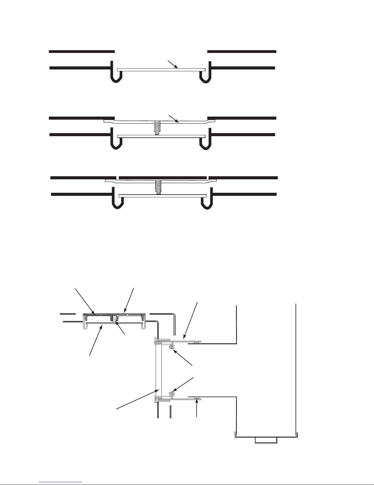
Top to Rear Flue Conversion
Internal
blanking
plate
Middle
securing
plate
Retaining
screw
Outer
blanking
plate
T pipe
adapter
(AC006)
Joint sealed
with suitable
material
T pipe
Clips
(supplied with
T adapter)
Rear
flue
spigot
Rear Flue Connection
(optional connection) order number MS9212
2) Insert the middle securing plate so it sits directly above the inner blanking plate with either end underneath
the top plate of the stove.
Inner blanking plate
Middle securing plate
3) Using one of the three screws provided in the kit, screw it into the hole in the centre of the securing plate
until it locks the securing plate up against the top plate of the stove and the screw head is flush with the hole
in the middle securing plate.
4) Place the outer blanking plate in the top flue outlet.
Fitting of the Top Flue Blanking Kit.
1) Place the inner blanking plate in the neck of the top flue outlet
Page 8
© EUROHEAT DISTRIBUTORS (H.B.S) LTD. Nov 2006
E & OE Instructions Part number IN1140 Ed A
8
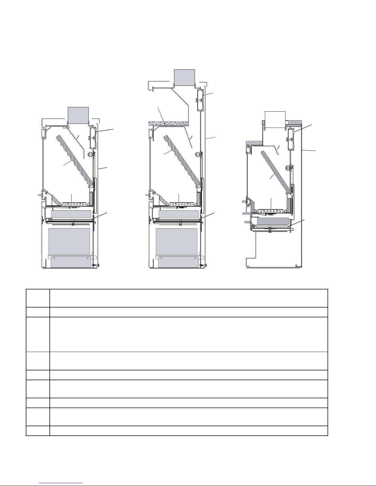
Vertical cross-section of the
Beethoven, Beethoven H, Monet, Monet H, Mozart, Ravel, Vivaldi, Hwam 30 & Hwam
60
B1: Stoves without cooking section B2: Stoves with cooking section B3: Ravel
1
2
5
7
4
6
1
5
6
7
4
8
8
5
6
7
4
8
2
1
8
3
2
Part
No.
Description and fitting
1 Mica board back plate. Must be placed on the rear edge of the inside holders.
2 Baffle plate. Is hung up on 3 hooks under the top plate. The front /middle hook has an extra
bent tag as transport security. This tag should be removed before fitting of the stove. In stoves
with a cooking section, the baffle plate is bent in at the bottom under the cooking section
(B2)
3 Protection plate, is placed under the tile in the cooking section.
(only stoves with ceramic tiles)
4 Cover plate. Should always cover the grate when burning wood.
5 Rear flue outlet. At the factory this is sealed with a external and an internal cover plate. The
rear flue outlet is therefore hidden behind the plate.
6 Removable rear heat shield, covering automatic controls.
7 Loose heat shield under the ash pan. This can be used as a lid when the ash pan is removed
for emptying.
8 Sliding draw with basket for pokers. Only supplied with Monet.
B1
B2
B3
Page 9

E & OE Instructions Part number IN1140 Ed A
9
© EUROHEAT DISTRIBUTORS (H.B.S) LTD. Nov 2006
Mounting of the cooking section.
Before mounting the cooking section, the covers and the rings for the cooking holes should be removed, and
the smoke outlet to the rear is closed. After this a new 5 mm rope seal gasket (8) is placed down into the flue
outlet socket (drawing D1). At the same time a gasket (9) supplied with the baking section is placed round in
the edge of the cooking holes (drawing D2). Then the baking section (12) is placed on top of the stove so the
flue inlet socket of the baking section is standing down in the flue outlet as well as in the cooking holes on
top of the stove. The flue (11) is connected, and the cooking holes are closed with the cover plates using the
cooking holes from the stove.
The function of the baking section.
When the by-pass damper of the cooking section is pushed in, the hot flue gases are conducted up around
the cooking section, thus giving the maximum heat in the baking section.When the by-pass damper (7) of the
cooking section is pulled completely out, the flue gases are conducted behind the cooking section and directly
out into the chimney, thus giving minimum heat in the cooking section. Consequently, the temperature in the
baking section is regulated by opening the by-pass damper more or less.
Mounting of the wood storage area.
The base, wood storage area (6) is placed where the stove is to stand, and the stove is placed on top of it.
The four guide pins on the base must locate in the legs of the stove.If the stove is not level after the stove is
mounted onto the base, this may be adjusted by means of two screws (10) mounted at the back of the base.
Page 10
© EUROHEAT DISTRIBUTORS (H.B.S) LTD. Nov 2006
E & OE Instructions Part number IN1140 Ed A
10
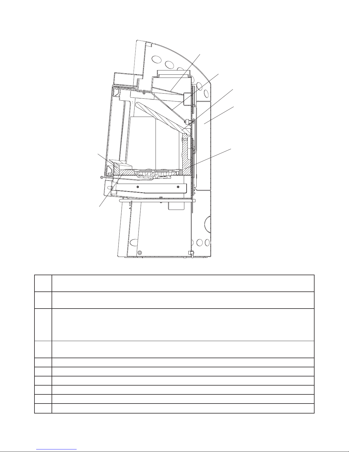
Vertical cross-section of the Figaro
1
2
3
5
6
7
8
4
9
Part
No.
Description and fitting
1 Mica board fire box top baffle. Should rest on the back plate and the angled side plates. It
should slot into the groove on the back plate.
2 Upper secondary combustion baffle plate. Should rest on the air channel for secondary
combustion, on the angled sides and against the front plate, and it should be pushed in as far
back as possible.To reach the upper secondary combustion baffle plate, the lower secondary
combustion baffle plate needs to be removed.
3 Lower secondary combustion baffle plate. Is secured by two tapered keys, each of which is
pushed into its own eyelet on the internal top plate.
4 Removable back plate, which conceals the automatics.
5 Rear side plates.
6 Front side plates.
7 Mica board back plate.
8 Front mica board.
9
Lower front mica board.
Page 11
E & OE Instructions Part number IN1140 Ed A
11
© EUROHEAT DISTRIBUTORS (H.B.S) LTD. Nov 2006
Hearths
The stove should stand wholly above a hearth constructed of suitably robust materials and should be able to
accommodate the weight of the appliance and its unsupported flue components. The materials should conform
to local Building Regulations and British Standards.
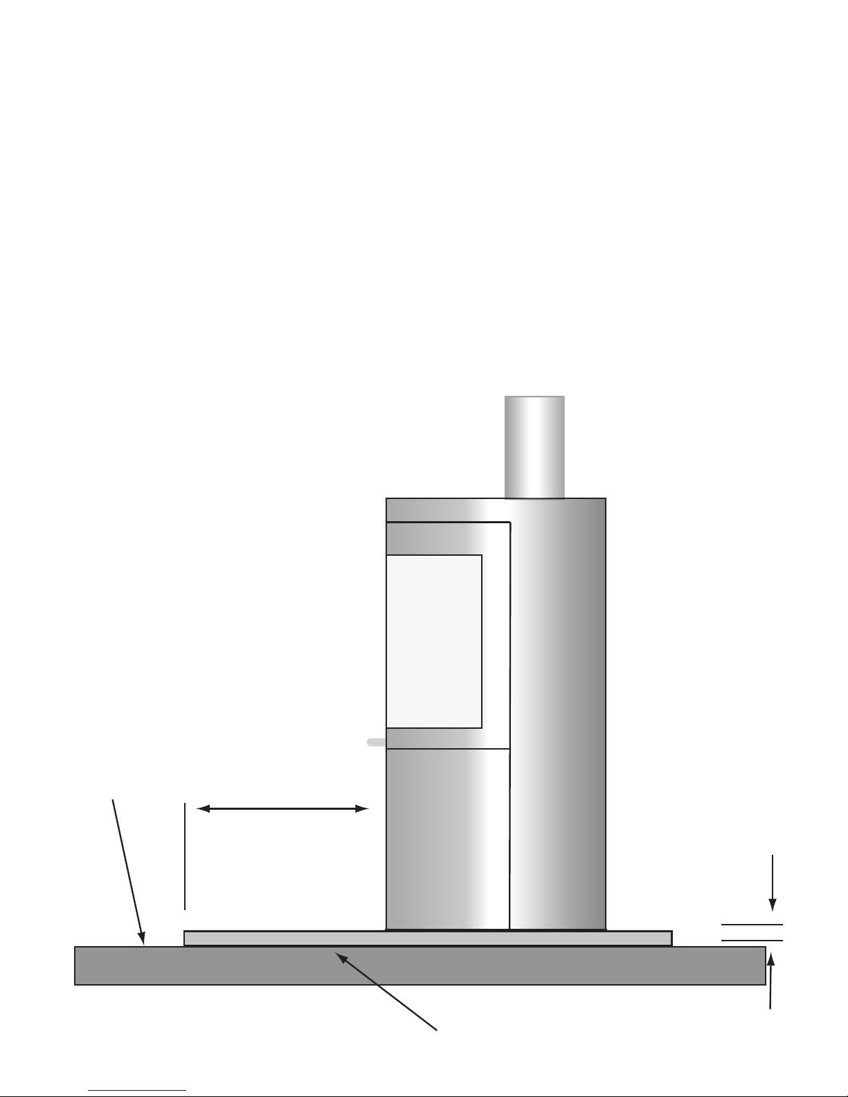
If the stove is not to stand in an appliance recess, a hearth made of non-combustible board/sheet material or
tiles of at least 12mm thick may be used as long as the floor can accommodate the weight of the appliance
and its unsupported flue components. If it is installed on a wooden floor or similar, the floor must be covered
with a non-combustible material, a minimum of 12mm thick, to a distance of 300mm in front of the stove and
150mm to each side measuring from the closed door of the combustion chamber.
The Hwam range of wood and multifuel stoves have been tested and conform to standards DIN18891 and DIN
18891-A1 where the hearth temperature does not exceed 100°C
For further information on hearths of either glass, granite or slate visit our web site
www.euroheat.co.uk
Appliance independently tested to verify that the hearth temprature does not exceed 100°C
Non-combustable board
sheet material or tile
Combustible
material
300mm
12mm
Page 12
© EUROHEAT DISTRIBUTORS (H.B.S) LTD. Nov 2006
E & OE Instructions Part number IN1140 Ed A
12
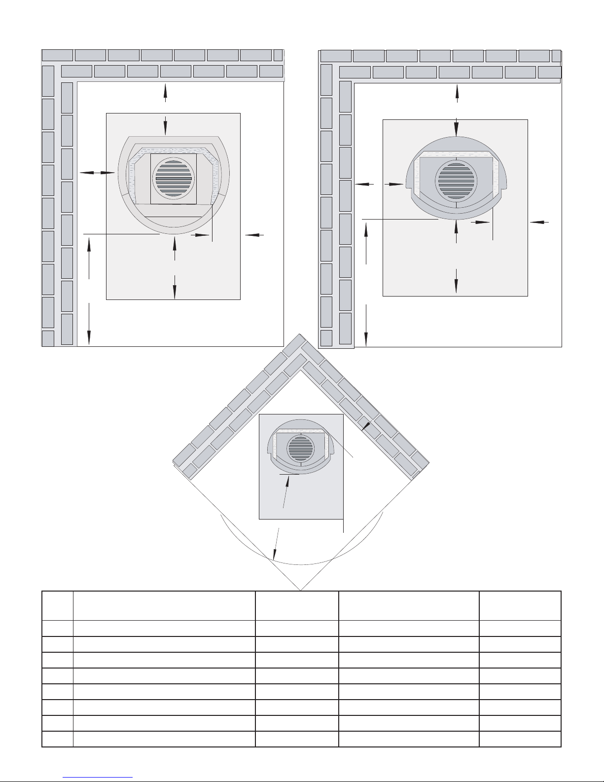
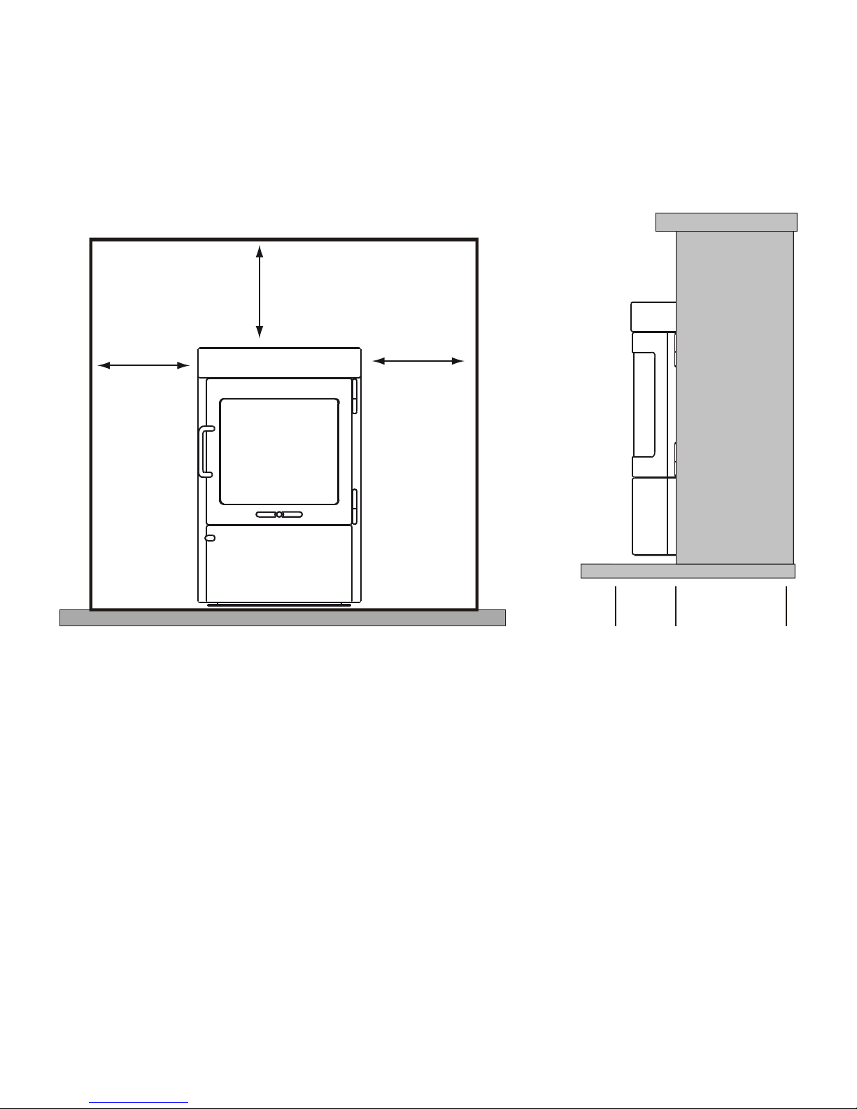
Installation Clearances
Beethoven, Dali, Monet, Mozart, Ravel, Vivaldi, Hwam 30 & 60 and Figaro
Free Standing Installation
Monet
Monet H
Beethoven, Beethoven H,
Ravel, Vivaldi, Mozart
Figaro
1 From non combustible back wall 100mm 100mm 100mm
1 From combustible back wall 150mm 150mm 150mm
2 From non combustible side wall 100mm 100mm 100mm
2 From combustible side wall 300mm 300mm 400mm
3 Fireproof hearth in front 300mm 300mm 300mm
4 Distance to 450 sidewall 150mm 150mm 100mm
5 From opening to edge of hearth plate 150mm 150mm 300mm
6 Distance from furnishings in front 700mm 700mm 900mm
If the stove is to be installed into
a fireplace recess the installation
must comply to BS8303 1 to 3:
1994
1
5
6
3
2
1
2
5
6
3
4
6
Page 13
E & OE Instructions Part number IN1140 Ed A
13
© EUROHEAT DISTRIBUTORS (H.B.S) LTD. Nov 2006
Do not be tempted to fit the stove into an unsuitable fireplace. Beyond the requirements of Building
Regulations and access to facilitate servicing the stove, providing a setting which will compliment a stove is
not a luxury, it is the practicality of making the most of an investment. A good builder or fireplace specialist
will be able to transform even the most utilitarian of fireplaces. Whether altering its proportions to those of the
“Golden Mean” ideal, see below, or exposing a wooden or stone lintel or simply removing superfluous detailing
for a comparatively small cost, and the result will be a pleasure for many years.
“Golden Mean”
1. The stove must always stand perfectly level. Adjustment screws and/or triangular plastic levelling spacers
may be provided with the stove. The provision of a suitable level hearth within the recess is an important
consideration when planning a fireplace.
2. Sufficient space should be allowed for service work.
3. At least the minimum clearance from inflammable materials and conforming to the current Building
Regulations.
4. Sufficient space around the stove so that the controls may be operated without the risk of injury to the
operator.
5. Mounting brackets should be installed to facilitate the secure fitting of a fire guard, if one is to be fitted to
protect the young, elderly or infirm.
6. Curtains and soft furnishings should be a minimum of 1m from the stoves body or the surface temperature of
these furnishings must not exceed 65°C.
7. The mounting of expensive paintings, mirrors and plasma screen televisions above a fireplace is not
recommended.
Fireplace Design
1
2/3
2/3
1/3 2/3
Page 14
© EUROHEAT DISTRIBUTORS (H.B.S) LTD. Nov 2006
E & OE Instructions Part number IN1140 Ed A
14
Fresh Air System
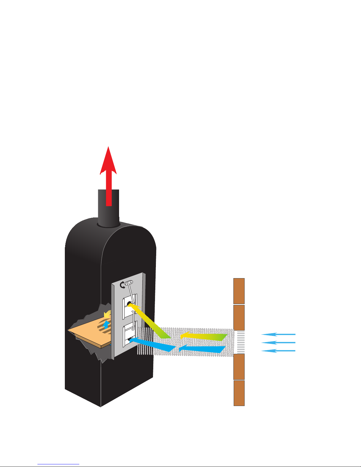
Instead of letting the air from the room into the stove for combustion, it is possible to take in fresh air from
outside and introduce this directly via a duct into the back of the stove.
Today, many modern dwellings are so airtight to conform with building regulations that it is an advantage to
attach a fresh air intake to the stove. This continually supplies the air for combustion while the stove is in use
but as the air is ducted directly into the back of the stove it stops cold fresh air mixing with the warm air in the
room chilling the room or causing draughts.
This ensures that the air extracter fan outlets in the kitchen and bathroom function optimally without effecting
the air required for combustion. The advantage of this is that a multifuel stove may now be fitted into a room
where an air extracter fan is fitted, however a flue draught test must be carried out with the extracter fan
running at its maximum setting to ensure that the fan is not drawing air from the stove.
Fresh Air Systems are available. See www.euroheat.co.uk for further information.
Fresh Air Duct
Fresh
Air Inlet
Page 15
E & OE Instructions Part number IN1140 Ed A
15
© EUROHEAT DISTRIBUTORS (H.B.S) LTD. Nov 2006
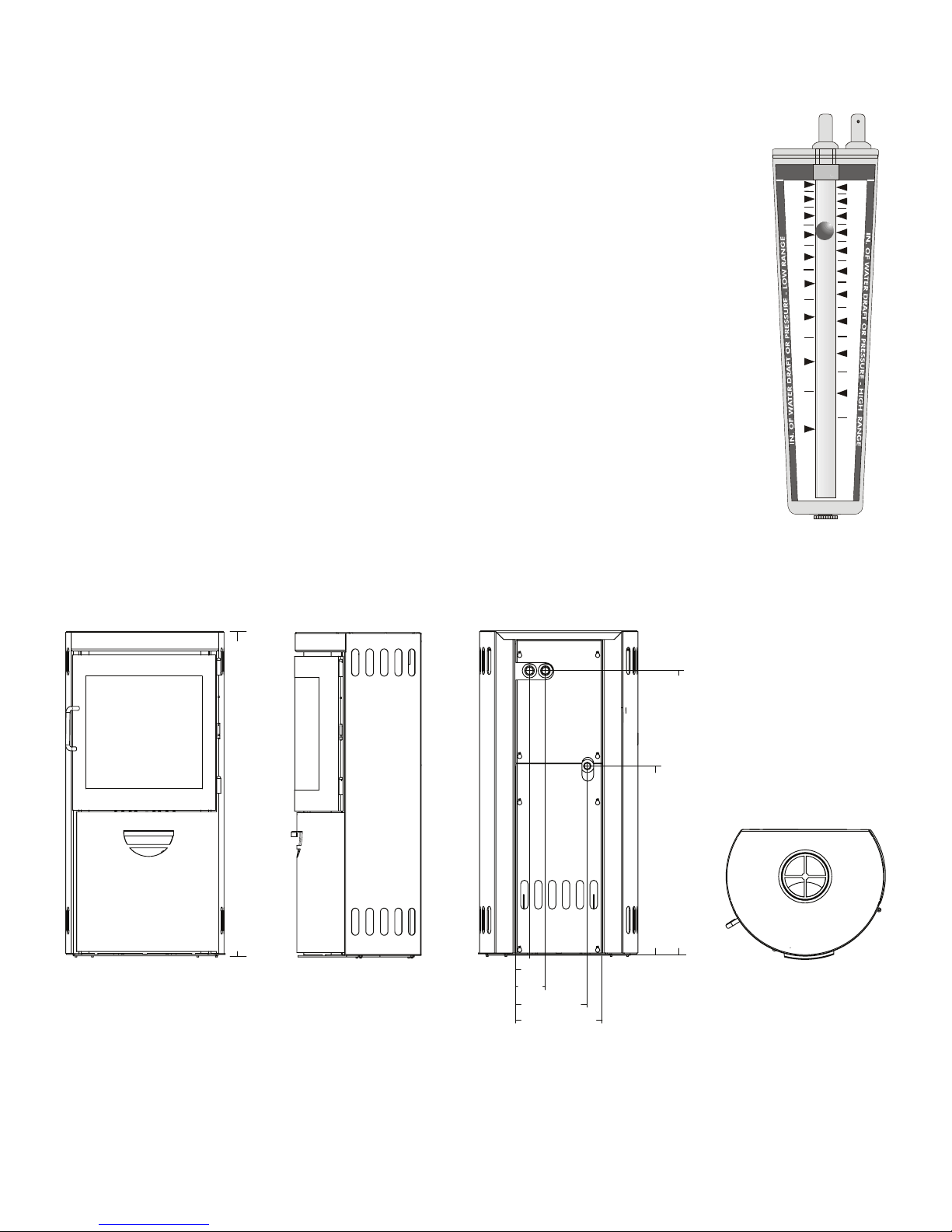
Flue Draught Measurement
A flue draught which is too low will result in the stove being difficult to light, responding only slowly to
demands for increased output and unable to reach its full heating output. If this is the case
rectification work of the chimney construction should be under taken. A flue draught which
is too high will cause difficult control conditions, and makes it possible to over fire the stove,
which can seriously damage it. In this instance a flue draught stabiliser may need to be fitted
or if it is wind assisted excessive flue draught a stabilizing cowl may need to be fitted.
The negative pressure created within the combustion chamber of the stove must be measured
using a test hole drilled into the flue, as close to the stove as possible and before any draught
stabilizer that may be fitted to the flue.To ensure a constant air inlet size the readings should
be taken with the air inlet controls set at maximum.
.05
.1
.2
.3
.4
.5
.6
.7
.8
.9
1.0
.02
.01
.03
.04
.05
.06
.07
.08
.09
Euroheat can supply the flue measurement gauges.
Order number MS026.
Note this is not a water gauge
used to measure gas pressure.
Stoves with a Water Jacket
Monet with 3kW Water Jacket
655
985
1123
102
247
299
47
Page 16
© EUROHEAT DISTRIBUTORS (H.B.S) LTD. Nov 2006
E & OE Instructions Part number IN1140 Ed A
16
Water Heating
It is the responsibility of the installer to ensure that the installation meets all the relevant regulations,
requirements and recommendations. The following information is given for interest only and should not be
used as a guide for installation.
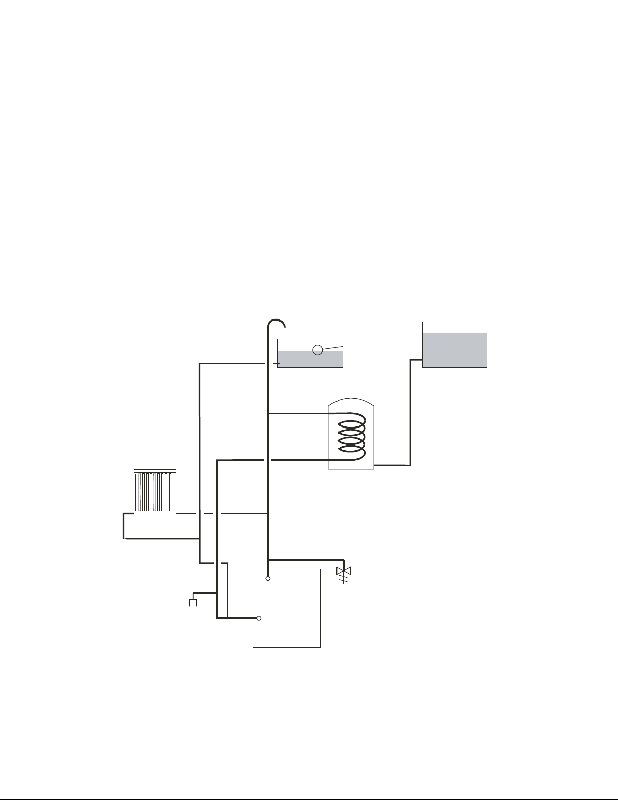
Pipe Work
The primary circuit must be a gravity system, the domestic hot water storage cylinder and heat leak radiator
should be positioned so as to provide a gravity circuit, with the flow and return pipes to be installed as
vertically as possible. Horizontal pipe runs should be avoided but where this is impossible the runs should
be made to rise towards the storage cylinder with an incline as steep as practicable. All changes of direction
should be made with bends rather than elbows, and using pipe of not less than 28mm bore. No valves or any
other device which may restrict or stop the flow must ever be fitted to this circuit.
and heat leak radiator.
Suggested installation for stove heating domestic hot water
Heat leak Radiator
Header tank
Hot water cylinder
Cold water header tank
Page 17
E & OE Instructions Part number IN1140 Ed A
17
© EUROHEAT DISTRIBUTORS (H.B.S) LTD. Nov 2006
Maintenance Instructions
Monet, Mozart, Dali, Beethoven, Vivaldi, Ravel, Hwam 30 and Hwam 60
Service inspection
Your stove should be given a thorough service inspection once a year. This includes:
• Thorough cleaning of the stove.
• Adjusting handles and door.• Lubricating the hinges with copper grease.
• Replacing springs in the automatic combustion system, where necessary.
• Checking the automatic combustion system.
• Checking and/or replacing gaskets. Glass door gaskets must always be replaced.
• Checking and/or replacing mica board stove lining material.
• Checking the construction.
• Checking the bottom and/or riddling grate.
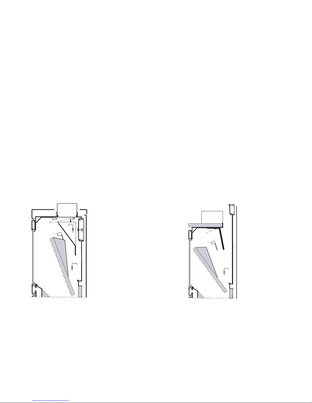
Cleaning the inside of the stove
Before cleaning, move the burn rate control rod to the far left in order to avoid soot and ash getting into
the automatic controls.The rear mica board baffle and baffle plate must be removed from the stove before
cleaning. Stoves with a cooking section need only remove the rear mica board baffle.
Diagram F
F1: Stoves without cooking section F2: Stoves with cooking section
5
3
4
1
2
F1
3
1
2
6
7
F2
• First lift the rear mica baffle (1) from the rail at the base (2).
• Next, lower it under the holders (3) and slide it out at an angle.
• The baffle plate (4) is lifted from the holders (5), under the top plate and edged out.
• If the baffle plate (6) has to be removed from stoves with cooking section, the bottom stones are
removed from the cooking section.
• After this the screws (7) are removed. If necessary change the screws when reassembling.
Page 18
© EUROHEAT DISTRIBUTORS (H.B.S) LTD. Nov 2006
E & OE Instructions Part number IN1140 Ed A
18
Loose Handles
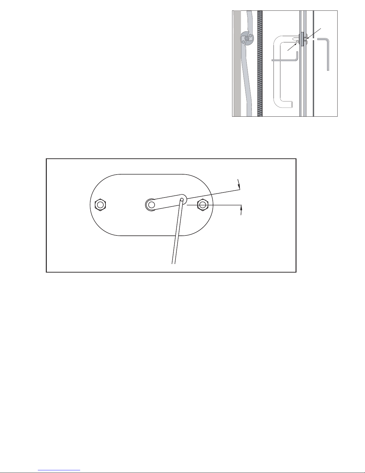
The handle on the door may loosen slightly after being
used for some time. If this happens it can be easily
tightened again. Loosen the Allen key screw (1) on the
lower side of the handle with a 2.5 mm Allen key. Then
tighten the central screw (2) on the handle with a 4 mm
Allen key through the little hole inside the door. Tighten
the Allen key screw (1) on the lower side of the handle.
H
1
2
Automatic Combustion Control
10°
Lift off the rear panel.
On a cold stove, the starting point of the mechanism is controlled. The starting point on a cold stove is
about 10° above horizontal.
It should move easily and spring loaded when you push it, no matter if the stove is cold or hot.
With a rising or falling temperatures it should move gradually.
The damper plates must be dry and clean and slide together unhindered.
Control bars and slide gates may have to be smeared with WD40.
Insulation (Skamolex)
The mica board insulation material of the combustion chamber may, in time, become worn and
damaged. Cracks in the insulation have no effect on the efficiency of the stove. The insulation should be
replaced, however, when it is reduced to less than half the original thickness due to wear and tear.
Page 19

E & OE Instructions Part number IN1140 Ed A
19
© EUROHEAT DISTRIBUTORS (H.B.S) LTD. Nov 2006
Maintenance Instructions
Figaro
Service inspection
Your stove should be given a thorough service inspection once a year. This includes:
• Thorough cleaning of the stove.
• Adjusting handles and door.
• Lubricating the hinges with copper grease.
• Replacing springs in the automatic combustion system, where necessary.
• Checking the automatic combustion system.
• Checking and/or replacing gaskets. Glass door gaskets must always be replaced.
• Checking and/or replacing mica board insulation material.
• Checking the construction.
• Checking the bottom and/or riddling grate.
Cleaning
Before sweeping, the regulator arm should be pushed fully to the left to prevent soot and ashes getting into
the automatics.
The smoke shelf and smoke channelling plates should be removed from the stove before cleaning.
See sectional drawing page 14.
1. The combustion chamber’s front mica board (8) is removed.
2. The lower front mica board is removed (9).
3. The front side plates (6) are removed.
4. The rear side plates (5) are removed.
5. The mica board fire box top baffle (1) is lifted out of the groove in the back plate (7) and tilted to
remove.
6. The lower secondary combustion baffle plate(3) is removed. The baffle plate is loosened by
removing the two tapered keys which secure the plate.
7. The upper secondary combustion baffle plate (2) is lifted out (the rear is tilted upward).
Automatic Combustion Control
See picture and instructions on page 18
Lift off the rear panel.
On a cold stove, the starting point of the mechanism is controlled. The starting point on a cold stove is about
10° above horizontal.
It should move easily and spring loaded when you push it, no matter if the stove is cold or hot.
With a rising or falling temperatures it should move gradually.
The damper plates must be dry and clean and slide together unhindered.
Control bars and slide gates may have to be smeared with WD40.
Insulation (Skamolex)
The mica board insulation material of the combustion chamber may, in time, become worn and damaged.
Cracks in the insulation have no effect on the efficiency of the stove. The insulation should be replaced,
however, when it is reduced to less than half the original thickness due to wear and tear.
Page 20
© EUROHEAT DISTRIBUTORS (H.B.S) LTD. Nov 2006
E & OE Instructions Part number IN1140 Ed A
20
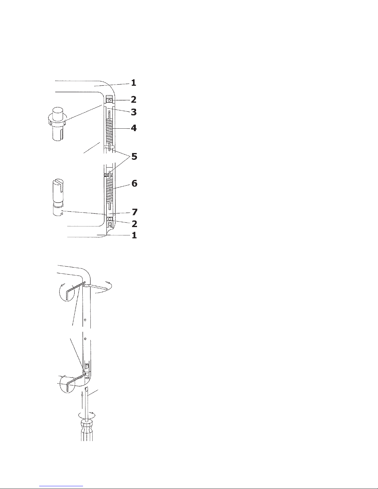
List of items:
1. Hinge pipe 14mm
2. Pinol screw M 4 x4 mm, 2 pcs.
3. Pivot with collar, 1 pcs.
4. Coil spring (right turned), 1 pcs.
5. Pinol screw M 4 x 12mm, 2 pcs.
6. Coil spring (left turned), 1 pcs.
7. Pivot with nick, 1 pcs.
All HWAM stoves are tted with a Bauart 1 hinge system (self closing door). A self closing door is an
option in the UK. The system can be adjusted for automatic or non automatic closing.
To enable automatic closing
Tightening the Bauart 1 Hinge
Loosen the top pinol screw. The spring is tightened by
turning the pivot about one round to the right with a
screwdriver. Tighten the pinol screw so the pivot is locked
in place
Now loosen the bottom pinol screw and tighten the spring
by turning the pivot to the right with a screw driver. Finally,
lock the pivot with the pinol screw.
The two springs should be tighten so that the door closes
on its own.
Disassembly of the door
Loosen both the top and the bottom pinol screw.
The bottom pivot is either push up into the hinge part with
a thin screw driver, or is pulled out with a M 4 machine
screw which can be screw into the pivot
Then pull the bottom part of the hinge to the side and lift
the door free from the top pivot
Hinge Adjustment
Page 21

E & OE Instructions Part number IN1140 Ed A
21
© EUROHEAT DISTRIBUTORS (H.B.S) LTD. Nov 2006
Commissioning Check List
Inspect the door and glass seals and ensure all handle latches are adjusted correctly, procedure in the operating
instructions.
Check baffle is installed correctly and that the riddling mechanism is operating.
Ensure that the fire responds to the operation of the controls and that there are no visible emissions of the
combustion products into the room.
Check the flue draught is within the parameters within these instructions. If the draught is excessive fit a
suitable flue stabiliser. If below the requirements rectify the flue installation.
Instruct the user on the use of the tools, operation of the appliance and the summer shut down procedure.
Information in the operating instructions.
Instruct the user never to operate the stove with the furnace door open and that the user is aware of the
requirement of a suitable fire guard where children, the old or infirm may come into contact with the
appliance.
Hand over the installation instructions, operating instructions and completed warranty form to the user. Remind
the owner to return the warranty form for registration.
Complete the Stoves Registration Form and Pass to User for
Registration
Euroheat and Hwam have a policy of continual research and development and reserve the right to modify its
appliances without prior notice.
We make every effort to ensure that the information provided in this document is correct and accurate at the
time of printing. Continued updates occur to adapt documents to customer requirements and appliance changes.
For the latest editions of all Euroheat documentation visit our web site
www.euroheat.co.uk.
We would request that you inform Euroheat of information which you feel is not provided in this document which
would assist other users in the future.
The Euroheat Technical Team
Welcome to the world of real Stoves
Euroheat Technical Team
X
Mark box when completed
 Loading...