

HVS FP3500-T11, FP3600-T11 Installation Manual
1
FP3500-T11/FP3600-T11
Installation Guide
FP unit (1)
Installation Guide (1) (this manual) Warning/Caution Information (1)
Installation Gasket (1)(attached to the FP unit)
Installation Brackets (4/set, 1set) USB Cable Clamp(2)
This unit has been carefully packed, with special attention to quality. However, should
you find anything damaged or missing, please contact your local FP distributor
immediately.
An FP-3500T/3600T series unit needs the following software for operation. As FP user
manual, provided by PDF media, describes its details, download the manual below and
get the further information. Visit our website below and get both software and reference
manual. (URL:http://www.pro-face.com/otasuke/)
• Software : Mouse Emulation Software
• Manual : FP-3500T/3600T/3650T series User Manual
Caution
Be sure to read the “Warning/Caution Information” on the attached sheet before using
the product.
Package Contents
Required software/Reference manual
DIS TRI BUTEU R C O NSEI L DEPUI S 1985
System
Email :
2 rue René Laennec 51500 Taissy France
Fax: 03 26 85 19 08, Tel : 03 26 82 49 29
hvssystem@hvssystem.com
Site web : www.hvssystem.com
Distribué par :
2
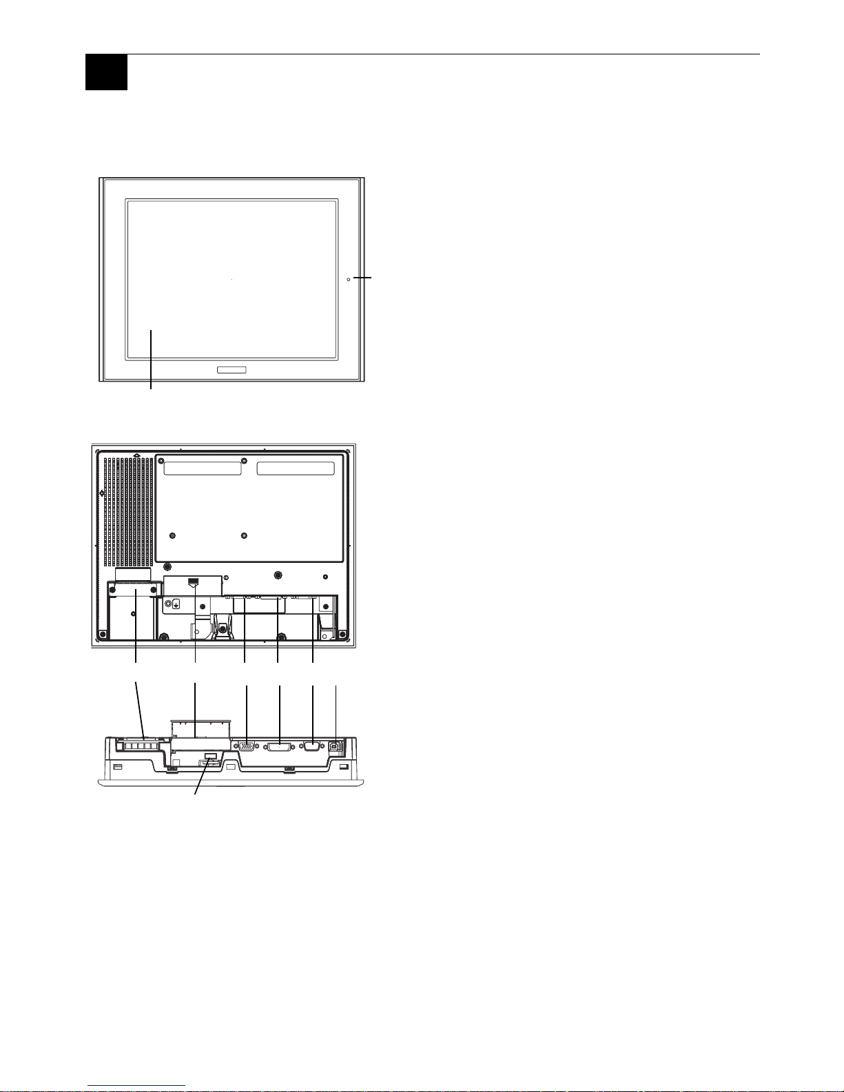
1 Part Names
C
D
E
F
G
H
Front View
Rear View
Bottom View
A,B
J
I
A: TFT Color LCD
Acts as a display monitor for your host.
B: Touch Panel
Allows you to switch screens or write data to
the host.
C: Input Terminal Block
Provides the input and ground terminals for a
power cable.
D: Setting Switch
By opening the cover, the Dip switches and
slide switch are seen. Each switch can set a
operation mode.
E:Analog RGB Connector
Connector for analog RGB interface
F: DVI-D Interface Connector
Connector for DVI-D interface
G: Serial Connector
Connector for serial (RS-232C) interface.
Used for sending touch panel data to the
host.
H: USB Connector (Type B)
Connector for USB interface. Used for
sending touch panel data to the host or used
as an upstream port for USB-HUB.
I: Front LED
Used to indicate the condition of the power
supply, a backlight burnout or image signal
input.
J: USB Connector (Type A)
A downstream port for embedded USB-HUB
in conformity with USB2.0/1.1 standard,
which is used for connecting USB devices.
Connect the upstream port of the USB-HUB
(H:USB connector) to the Host PC for USB
connector use.
3
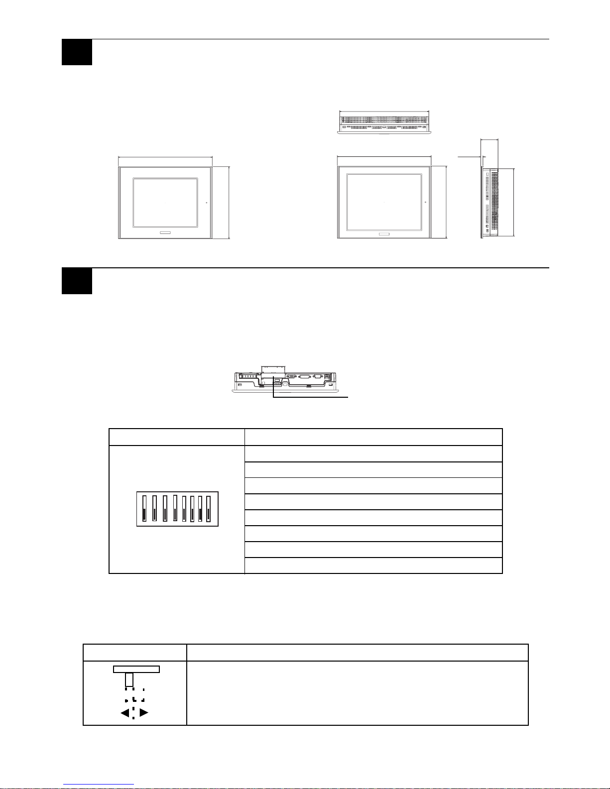
The Dip Switches and Slide Switch are located in the bottom of the FP unit. Only the
settings when the power supply is turned on is effective to the Dip Switches and the Slide
Switch. After changing the settings of the Dip Switches and the Slide Switch, be sure to
restart your FP unit
SW1
• SW1-2 Dip Switch SW1-2 is used to display or hide the OSD.
To hide the OSD, set the switch to ON. To display the OSD, set the switch to OFF.
The default setting is OFF. (OSD is displayed.)
SW2
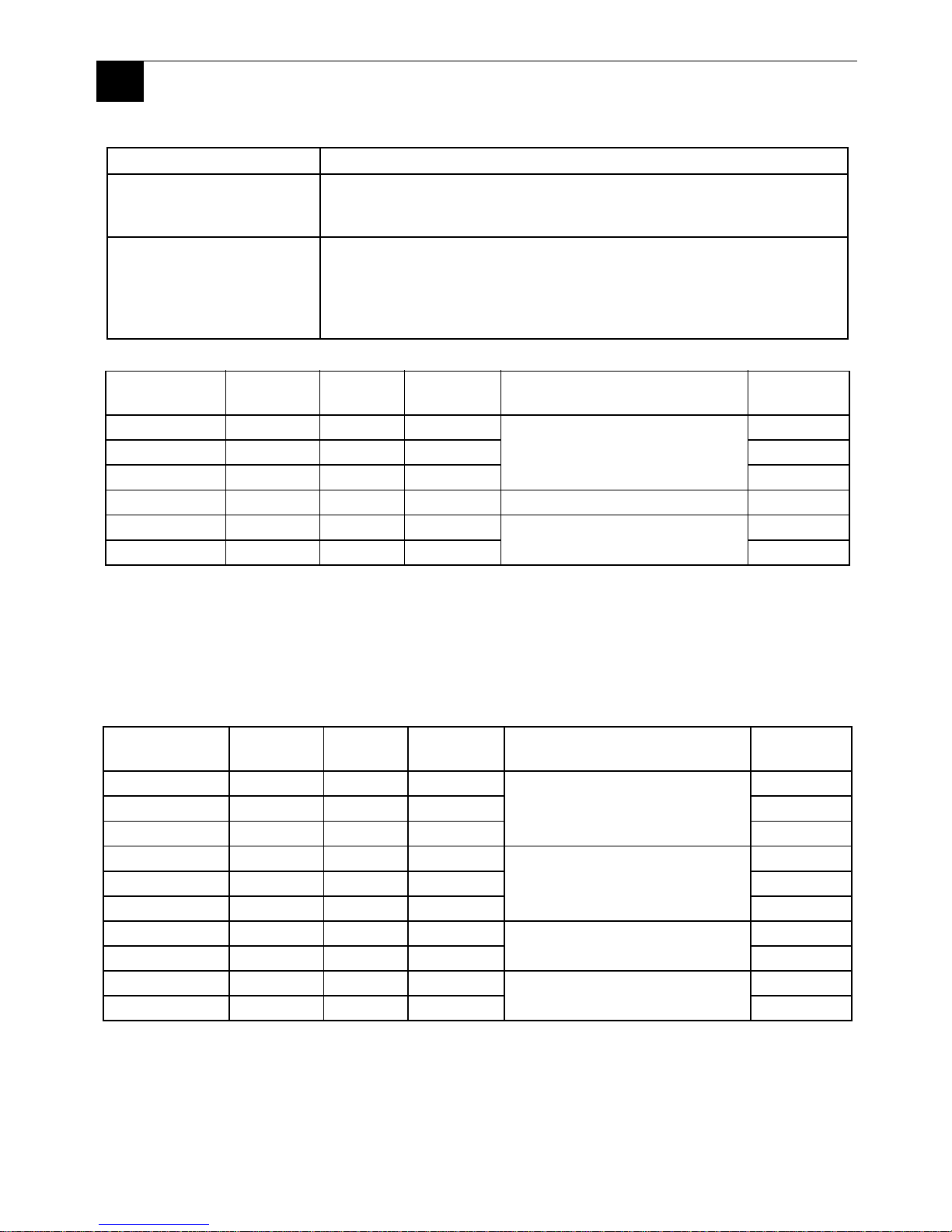
2 Dimensions
3 Dip Switches and Slide Switch
Switch Setting
SW1-1 Reserved (Always OFF)
SW1-2 Display/Hide the OSD
SW1-3 Reserved (Always OFF)
SW1-4 Reserved (Always OFF
SW1-5 Reserved (Always OFF)
SW1-6 Reserved (Always OFF)
SW1-7 Reserved (Always OFF)
SW1-8 Reserved (Always OFF)
Switch Setting
Slide Switch is used to switch the data input/output (command
control) method on the touch panel between USB and RS-232C
(Serial). The default setting is RS-232C.
301[11.85]
227[8.94]
58[2.28]
317[12.48]
243[9.57]
317[12.48]
243[9.57]
8[0.31]
Top View
Front View (FP3500-T11)
Side View
Unit: mm [in]
Front View (FP3600-T11)
Dip Switches(SW1)
Slide Switch(SW2)
Bottom View
ON
1
8
SW1
232
USB
4
Analog RGB Interface
Display Area (FP3500-T11)
Display Area (FP3600-T11)
4 Interfaces
Input signal type Analog RGB
Input signal
characteristic
Image signal : analog RGB
Synchronous signal :TTL level, negative true or positive true
Scanning type : non-interlace
Setting by OSD
(On Screen Display)
•CONTRAST
•H-POSITION
•H-size
•DIMMER(BACKLIGHT)
•ALL RESET (DEFAULT)
•BRIGHTNESS
•V-POSITION
•PHASE
•SHARPNESS
Size
H Sync.
(kHz)
V Sync.
(Hz)
Dot Clock
(MHz)
Screen Resolution Exp an s ion
(H: Horizontal)(V: Vertical)
Display
Resolution
640×350
*1
*1.
When the 350 pixel (vertical) signal setting is selected, 400 pixels, including 50
pixels at the top and at the bottom of the sc reen will be enlar ged and displa yed at 480
pixels (1.2times).
31.469 70.000 25.175
×1.0 (H)
×1.2 (V)
640×420
640×400 31.469 70.000 25.175 640×480
640×400 24.827 56.420 21.053 640×480
640×480 31.469 59.992 25.175 ×1.0 640×480
720×350
*
1*2
*2.
When you use this resolution, set “ON” for “720 × 400 Mode” in the OSD (On
Screen Display) “system settings”.
31.469 70.000 28.320
×0.89 (H)
×1.2 (V)
640×420
720×400
*
1
31.469 70.000 28.320 640×480
Size
H Sync.
(kHz)
V Sync.
(Hz)
Dot Clock
(MHz)
S
creen Resolution Expansion
(H: Horizontal)(V: Vertical)
Display
Resolution
640×350
*1
*1.
When the 350 pixel (vertical) signal setting is selected, 400 pixels, including 50
pixels at the top and at the bottom of the screen will be enlarged and displayed at 600
pixels (1.5times).
31.469 70.000 25.175
×1.25 (H)
×1.5 (V)
800×525
640×400 31.469 70.000 25.175 800×600
640×400 24.827 56.420 21.053 800×600
640×480 31.469 59.992 25.175
×1.25 (H)
×1.5 (V)
800×600
640×480 35.000 66.670 30.240 800×600
640×480 37.861 72.810 31.500 800×600
720×350
*
1*2
*2.
When you use this resolution, set “ON” for “720 × 400 Mode” in the OSD (On
Screen Display) “system settings”.
31.469 70.000 28.320
×1.1 (H)
×1.5 (V)
800×525
720×400
*
2
31.469 70.000 28.320 800×600
800×600 35.156 56.250 36.000
×1.0
800×600
800×600 37.879 60.317 40.000 800×600
5
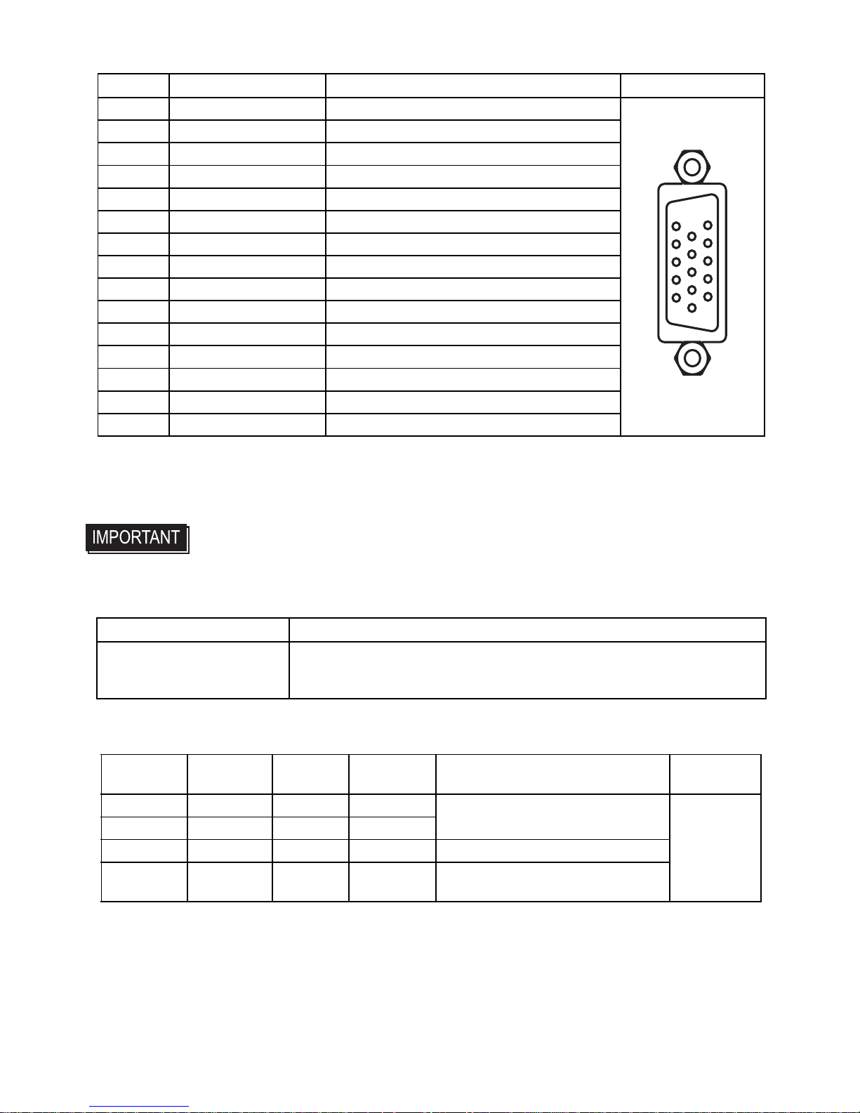
Pin Assignments and Signal Names for Analog RGB
Connector.................. Mini Dsub 15 pin male
Connector set screw.. Inch type (4-40)
Cable......................... RGB cable manufactured by Pro-face.
FP-CV02-45 <4.5m> (VGA standard)
DVI-D Interface
Display Area (FP3500-T11)
Pin No Signal Name Condition Pin Location
1 Analog R R signal input
2 Analog G G signal input
3 Analog B B signal input
4 Reserved NC (spare for input)
5 Digital grounding Digital signal GND
6 Return R R signal GND
7 Return G G signal GND
8 Return B B signal GND
9 Reserved NC (spare for input)
10 Digital grounding Digital signal GND
11 Reserved NC (spare for input)
12 DDC DATA DDC Data
13 H. SYNC Horizontal synchronous signal input
14 V. SYNC Vertical synchronous signal input
15 DDC CLK DDC Clock
• If a cable other than the specified RGB cable is used, product
performance cannot be guaranteed due to the possibility of noise
interfering with the FP unit’s operation.
Input signal type DVI-D
Setting by OSD
(On Screen Display)
•CONTRAST
•DIMMER(BACKLIGHT)
•ALL RESET (DEFAULT)
•BRIGHTNESS
•SHARPNESS
Size
H Sync.
(kHz)
V Sync.
(Hz)
Dot Clock
(MHz)
Screen Resolution Expansion
(H: Horizontal) (V: Vertical)
Display
Resolution
640×400 31.469 70.000 25.175
×1.0 (H)
×1.2 (V)
640×480
640×400 24.827 56.420 21.053
640×480 31.469 59.992 25.175 ×1.0
720×400
*1
*1.
When you use this resolution, set “ON” for “720 × 400 Mode” in the OSD (On
Screen Display) “system settings”.
31.469 70.000 28.320
×0.89 (H)
×1.2 (V)
15
11
5
1
 Loading...