

Page 1
User Manual
TD30
E N G L I S H
Rev 1.4
HV Diagnostics, Inc
North and South America
271 Rope Mill Pkwy, Ste2
Woodstock, GA 30188
USA
Tel. +1 678-445-2555
Fax +1 678-445-2557
www.hvdiagnostics.com
HV Diagnostics S.à.r.l.
Africa, Asia, Australia,
Middle East
www.hvdsa.com
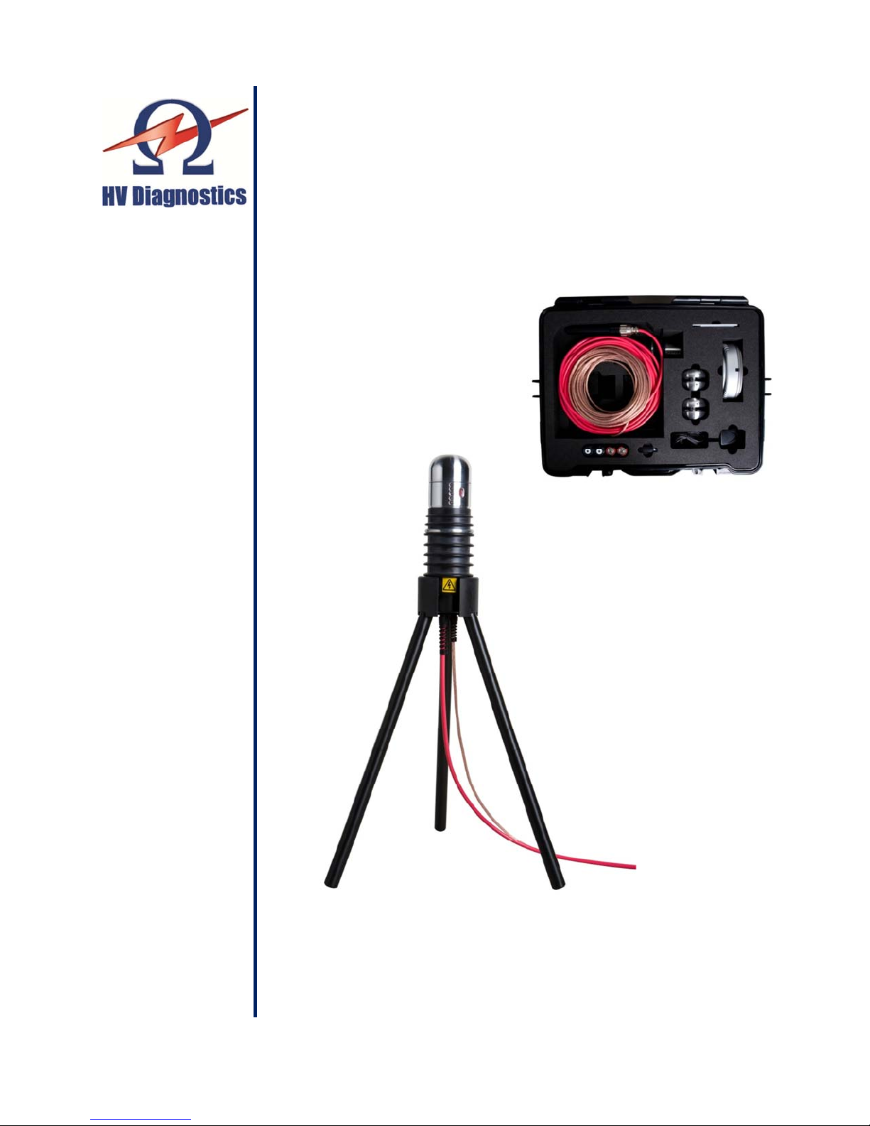
Portable Tan Delta Measurement System
Page 2

User Manual
Rev 1.4
Page
2 HV Diagnostics
Page 3
User Manual
HV Diagnostics
Page
3 Rev 1.4
Computer Notebook ID
TD System Ser No
COM Port #
Bluetooth Hardware
NOTE:
The information presented in this instruction manual is believed to be accurate and correct
for the intended use of this product. Should this instrument be used for other applications and
purposes not covered herein, please contact HV Diagnostics to validate its suitability. This
manual, all of its contents and the instruments specifications are subject to change without
notice.
Windows®, Windows 2000®, Windows XP®, Windows 7® are registered trademarks of Microsoft
Corporation.
Bluetooth® and the Bluetooth Label are owned by the Bluetooth SIG, Inc.
PDF and the Adobe Acrobat Family of Software are trademarks of Adobe Inc.
Space to note the used communication Parameters for your TD System:
Page 4

User Manual
Rev 1.4
Page
4 HV Diagnostics
Table of Contents
1 Forward ................................................................................................... 5
Regarding this Document ........................................................................ 5
1.1
Documentation Conventions ................................................................... 6
1.2
Legal Considerations .............................................................................. 7
1.3
2 Safety ..................................................................................................... 8
General Safety ........................................................................................ 8
2.1
Work Safety ............................................................................................ 8
2.2
3 Introduction ............................................................................................. 9
4 Features .................................................................................................. 9
5 Applications ............................................................................................ 9
6 General Description ...............................................................................10
Technical Specifications* .......................................................................10
6.1
Materials ................................................................................................11
6.2
7 Hardware Description .............................................................................13
8 Connecting up the TD30 Instrument .......................................................16
9 Software TD ControlCenter ....................................................................17
10 Instrument Care .....................................................................................24
Appendix A: Software Installation Procedure ‘TD ControlCenter’...................25
Appendix B: Bluetooth® Setup and Config Procedure ...................................26
Page 5

User Manual
HV Diagnostics
Page
5 Rev 1.4
User
Responsibilities
Focus
safety
1 Forward
Purpose
This operating manual serves to ensure the proper and safe use of the TD test instrument.
Regarding this Document
1.1
Target User
This operating manual is designed to inform various user groups. The scope and depth of the
information provided may not be appropriate for all users. However, it is important that all
users familiarize themselves with this document in full. The following is a guideline indicating
the most significant information as a function of the user’s responsibilities.
HVA Operator
Procurement,
Management
• To connect the equipment
• To carry out manual or pre-programmed test
sequence
• To verify validity of HVA application
• To verify validity of TD application
• To adjust instrument settings
• To program automatic test sequences in
ccordance with particular testing standards
a
• To assure that the workplace is safe and
has all required equipment
• To assure that HVA and TD operators are
qualified technicians
• To assure that operators fulfil their
responsibilities
All Sections
Particular focus on all
s
afety messages
Particular focus on
messages and information
regarding general product
description.
Page 6

User Manual
Rev 1.4
Page
6 HV Diagnostics
Blue circle with white exclamation mark: Used to indicate recommended
Documentation Conventions
1.2
The following explain the symbols, and safety messages found in this document. The
employment of safety symbols and signal words are according to the American National
Standards Institute standard ANSI Z535.6 "Product Safety Signs and Labels".
Safety Messages
Danger
Indicates a hazardous situation which if not avoided will result in death or
serious injury
Warning
Indicates a hazardous situation which if not avoided could result in death
or serious injury.
Caution
Indicates a hazardous situation which if not avoided could result in minor
or moderate injury.
DANGER
WARNING
CAUTION
Notice
Symbols
NOTICE
Indicates suggested practices to protect equipment and property.
Yellow triangle, framed in black: Used to indicate a potential hazard.
Only used in conjunction with description of the possible hazard!
Detailed symbol may correspond to this specific hazard.
Red outlined circle with red diagonal line: Used to indicate forbidden
practices.
The described handling practice must not be carried out!
precautionary measures or a situation that can lead to property damage.
Page 7

User Manual
HV Diagnostics
Page
7 Rev 1.4
Legal Considerations
1.3
Warranty
HV Diagnostics provides a one-year warranty from the original purchase date
of instrument for all necessary parts and labor. This warranty is void in the
event of abuse, incorrect operation or use, unauthorized modification or
repairs, or failure to perform the specified maintenance as indicated in this
operation manual. This warranty does not include normal consumable items
such as lamps, paper rolls, printer ribbons, batteries or other auxiliary items.
This warranty and our liability are limited to replacing or repairing defective
equipment, at our discretion. Equipment that is returned to HV Diagnostics
must be packed in original packaging. All shipped items must be prepaid and
insured. No other warranties are expressed or implied.
Contact Information
HV Diagnostics, Inc. H.V. Diagnostics S.à.r.l.
271 Rope Mill Pkwy. Africa, Asia, Australia,
Ste 2 Middle East
Woodstock, GA 30188 www.hvdsa.com
T. +1 678-445-2555
F. +1 678-445-2557
North and South America
www.hvdiagnostics.com
[email protected]
Copyright
©2006 HV Diagnostics. All rights reserved.
No part of this publication may be reproduced, transmitted, stored, or
translated in hardcopy or electronic form without the written consent of HV
Diagnostics.
Your opinion matters!
Your comments and suggestions are of value. We are dedicated to supporting
your needs. Offering you optimal documentation is part of our promise of
quality.
Improvement suggestions regarding this manual may be sent to:
Thank you for your feedback!
Page 8

User Manual
Rev 1.4
Page
8 HV Diagnostics
2 Safety
General Safety
2.1
Work Safety
2.2
Safety is priority! Respect all safety information; only use the TD for
appropriate applications and ensure that operators possess the required
operator qualifications.
NOTICE
Operation Manual
Before carrying out any high voltage test with this instrument, read this
Operating Manual in its entirety.
DANGER
Electric Shock Hazard
Never assume that equipment is safe to handle without using the
necessary safety equipment and grounding procedures.
• All procedures must comply with local safety regulations
• Always treat exposed connectors and conductors as potential electric
shock hazards. All cables and connectors must be inspected for
damage before use. Damaged equipment must not be used.
• All equipment to be high potential tested must be de-energized and
properly isolated from all power sources. All equipment grounds must
remain in place.
• DUT must be grounded, de-energized and isolated from
sources. DUT must be discharged and grounded before disconnecting
the test lead.
• All auxiliary electrical apparatus such as switchgear, surge arresters
etc. must be isolated from the test power source and the DUT.
• Ground connections must be made first and removed last!
• Avoid testing alone. In the event of an emergency another person’s
presence may be essential.
• The visual signals of the TD30 are designed to be easily distinguished
even under bright sunlight to avoid incorrect readings. Always keep at
least 6 feet / 2 meters distance when looking directly at the LED
signals. Avoid long direct exposure of eyes to the signals especially
under dark conditions.
The LED signal colors on the TD system indicate a TD value / range or equipment
status condition. These LED lights signals in no way indicate the presence or absence
of high voltage and the TD30 should be considered energized at all times when
connected to a potential voltage source like a HVA test system.
all power
Page 9

User Manual
HV Diagnostics
Page
9 Rev 1.4
3 Introduction
The TD30 model is an easy to use, single piece, Digital Signal Processor based, field
portable, fully automatic VLF (Very Low Frequency) high voltage measurement instrument
developed for the high potential measuring of the insulation dielectrics of various types of
electrical apparatus.
4 Features
• Lightweight, portable, battery powered unit
• Solid state air insulated design
• Suitable for use with the HVA30 VLF test systems.
• Test results are easily stored via Notebook Computer or PocketPC via wireless
Bluetooth® connection.
• Supplied complete with TD communication and analysis software – TD Control
Center.
• Real-time display of actual output waveform.
• Power Save (Sleep) function (1 hour of inactivity), automatic wakeup on reapplication
of high voltage. One-Click reconnect in ControlCenter after Sleep
5 Applications
The TD30 provides the testing and commissioning engineer/technician with a versatile
high voltage tan delta measuring system suitable for testing medium voltage electrical
insulation systems such as cables (including: XLPE, PE, EPR, PILC, etc.), capacitors,
switchgear, transformers, rotating machines, insulators and bushings.
Tan Delta testing enables the cable test engineer to detect insulation defects before the
cable fails in service. The TD30 is a versatile tan delta measuring system that is directly
connected to the HVA series of VLF test systems from HV Diagnostics. The tan delta test
results of the test object can now be easily measured and recorded and the results stored
on a standard PC or Laptop for analysis, trending or quality control. This enables the
cable engineer to now make tan delta testing a routine maintenance test.
The TD30 is a battery powered system that is directly connected to the HVA30 series of
VLF test systems. Standard “C” size alkaline or rechargeable battery cells that are
commonly available will last up to 10 hours of continuous operation.
The TD30 is supplied with 30 feet /10 meters of terminated output cable to plug directly
into the HVA30 test system and is supplied complete with operating software which gives
a complete picture of the tan delta measurement together with a real time display of the
output voltage and current. The data transmission to standard notebook PC or PDA that
is Bluetooth® enabled, thus eliminating a direct connection between the TD30 and the
data collection device.
Page 10

User Manual
Rev 1.4
Page
10 HV Diagnostics
6 General Description
Technical Specifications*
6.1
Characteristic TD30
Supply Power 2 C-Size Alkaline or NiMH Rechargeable Batteries
Operating Time Alkaline Batteries: min. 10 hours
Operating Time Rechargeable Battery: min 5 hours
Operating Time means uninterrupted use under full load. The
TD system incorporates an automatic power shutdown mode
during extended periods of inactivity which will further extend
the battery life.
Operating Voltage
Voltage Measurement
Operating Current
Current Measurement
Operating Frequency 0.1 Hz
Tan Delta Measurement 0.1 E-3 to 1000 E-3
Load Capability Limit Minimum Load: 5nF
Computer Interface Bluetooth® Class 1
HV Cable Test Lead Standard is 30 ft (10 m) with direct plug interface to HVA30
Operating Temperature 20 to 113°F / -5 to 45°C
Storage Temperature -13 to 155°F / -25 to 70°C
Relative Humidity 0-80% non-condensing.
Weight 11 lbs / 5 kg
Dimensions Length x Diameter: 11” x 3” / 28 cm x 8 cm
*Technical Specifications are subject to change. HV Diagnostics reserves the right to modify values in accordance with
future HVA development.
1 – 24 kVrms
Resolution 100 Vrms
Accuracy 0.5% of reading
0.001mA - 14 mA rms
Resolution 1 µArms
Accuracy 1% of reading
Resolution 0.1 E-3
Accuracy: Load > 15nF and < 500nF: +/-0.2 E-3
Accuracy: Load < 15nF and > 500nF: +/-0.5 E-3
max. Transmission Power 12dB @ range 45 ft (15 meters)
indoor fully Bluetooth® SIG™ certified communication
Series of HV Test Generators – other lengths are available.
Page 11
User Manual
HV Diagnostics
Page
11 Rev 1.4
Materials
6.2
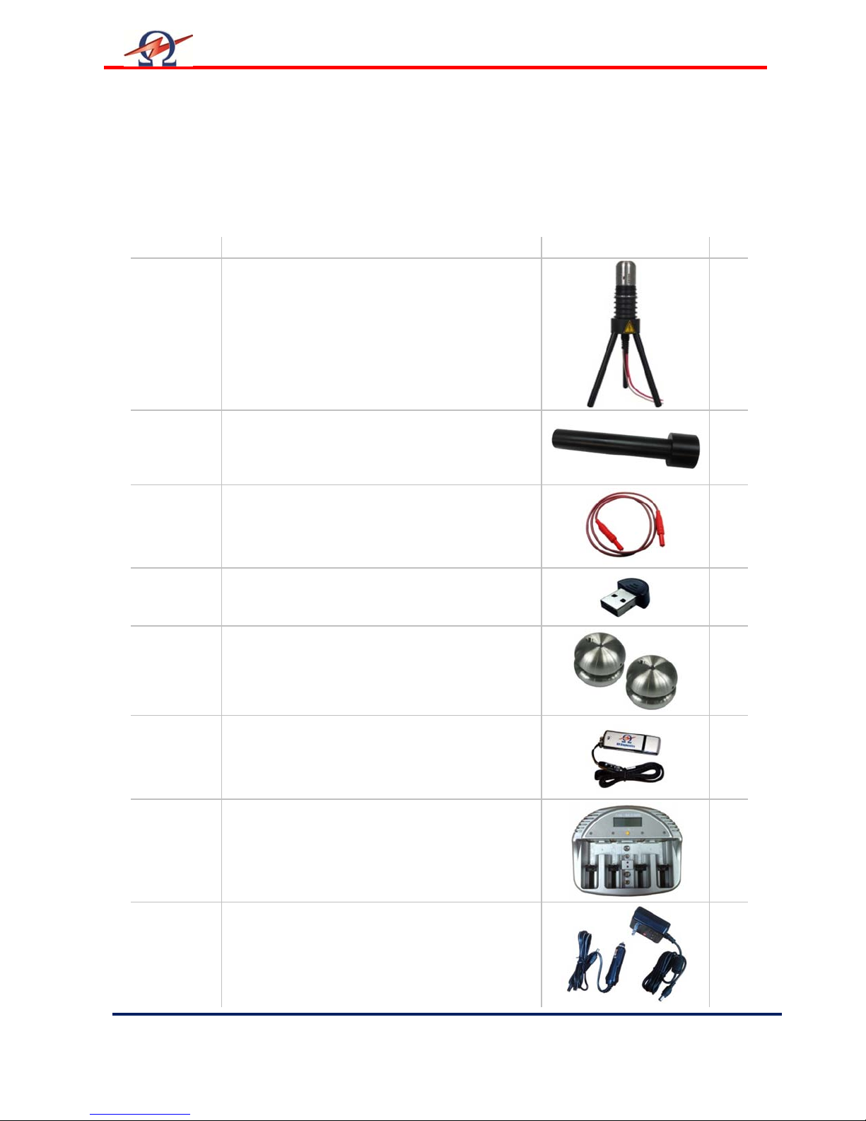
Shipment Content
Items included upon delivery of the HVA are listed below. The * marking
specifies items that are country specific. For inquiries, please contact HV
Diagnostics. For inquiries, please contact HV Diagnostics.
Part No. Item Description Qty
700 003 TD30 Tan-Delta System 24 kVrms
With TD stand
1
700 086 HV Protective Cap
700 062 Red Jumper Cable 36“/100cm
700 053 BlueTooth Adapter
700 050 Corona Protection Shield; 2 parts
USB Stick Flash Drive HV Diagnostics
Battery Charger
1
1
1
1
1
1
AC Power Adapter for Battery Charger*
DC Power Adapter for Battery Charger
1*
1
Page 12
User Manual
Rev 1.4
Page
12 HV Diagnostics
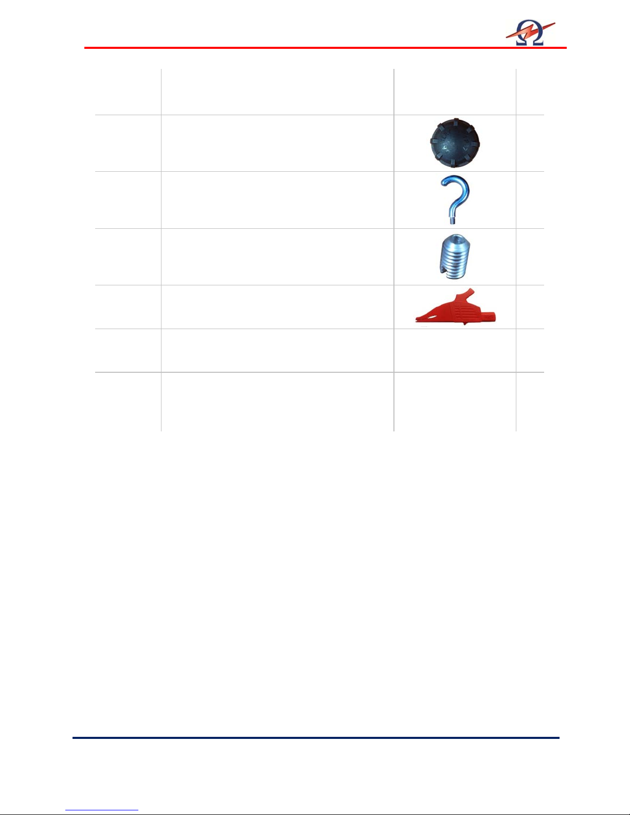
C Batteries
1.5 V
Battery Cap
Hooks
TD head inserts
Alligator Clip
TD30 Manual
4
2
1
3
1
1
TD Software: TD Control Center
(On USB Flash Drive)
1
Page 13
User Manual
HV Diagnostics
Page
13 Rev 1.4
Pos. Item Descrip
tion
4
3
1
5
6
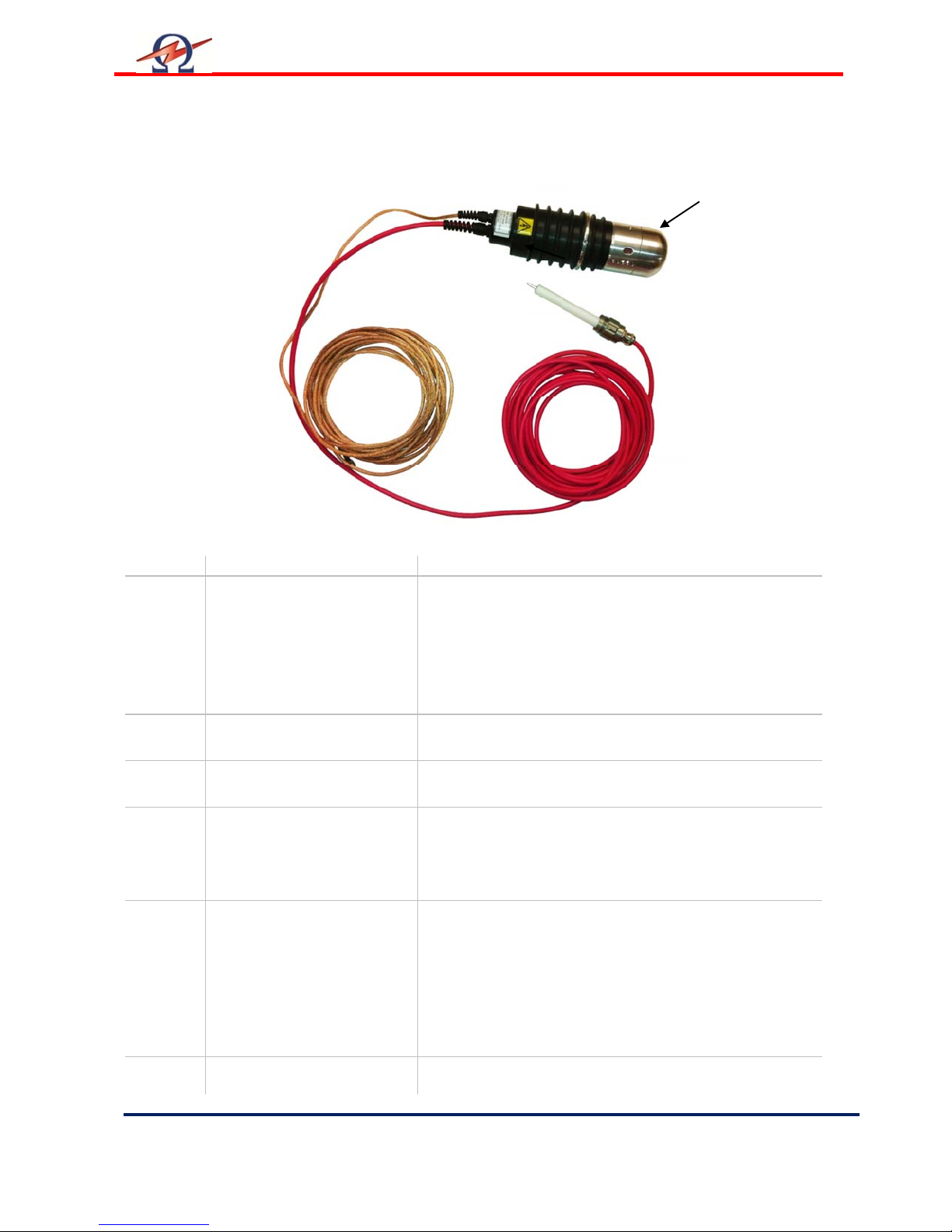
7 Hardware Description
2
1 TD System Housing The TD System housing/enclosure. Note the TD30 will
assume a potentially dangerous high potential /
voltage during testing and measurement. Always keep
the housing isolated and clear of any ground during
testing. Depending on the application, the 3-Pod
“Sputnik” Stand which is supplied can be used to
ensure proper isolation.
2 High Voltage Cable High Voltage connection cable that links the TD30 to the
HVA generator.
3 High Voltage Plug TD30 Plug directly into HVA30 HV output plug socket.
4 Ground/Earth Cable Ground connection for load / station ground.
Always connect this cable to a station ground. Do not
use this cable to “ground” the Device Under Test
without a suitable connection to a safe station / earth
ground.
5 Tan Delta Head
Tan Delta Head covers the main ON/OFF switch and
the battery housing. This head also incorporates an
8mm metric thread, which assists in providing a number
of different connection options to the DUT. Unscrew
head cap section to remove from the rest of the housing
to turn ON/OFF the system or to replace the batteries.
To re-install the head cap section, carefully screw on the
cap, taking care not to cross thread the connection.
6 LED and Bluetooth® RF 5 LEDs showing operation status information. Do not
cover this area.
Page 14
User Manual
Rev 1.4
Page
14 HV Diagnostics
Pos. Item Description
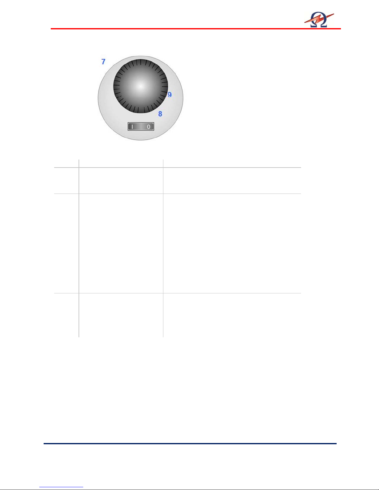
The Head of the TD30 system
with the Cap removed showing
the Battery compartment and
the ON / OFF switch.
7 TD system control By removing the Tan Delta head cap the main
switch and the battery housing can be
accessed.
8 Main Switch Switch for powering up or shutting down the TD
system. It is advisable to turn off the system to
conserve battery life if the system is not
planned to be used for an extended period of
time.
The TD system incorporates an automatic
power save sleep mode, which shuts down the
system after no voltage (<1kV) has being
sensed for 60 minutes or more. In this mode
the main switch has to be set to 0 (off) for about
2 minutes and then on again to wake up the
system manually, or you can reapply voltage
with the HVA which will also wake up the unit.
9 Battery Compartment Unscrew the cover of the battery compartment
to replace or install batteries. 2 of C-Size 1.5V
batteries are required. Insert the batteries with
the + positive upwards (towards the operator)
See Battery Cover for polarity marking if in
doubt.
Page 15
User Manual
HV Diagnostics
Page
15 Rev 1.4
Pos.
Item Description
of the system.
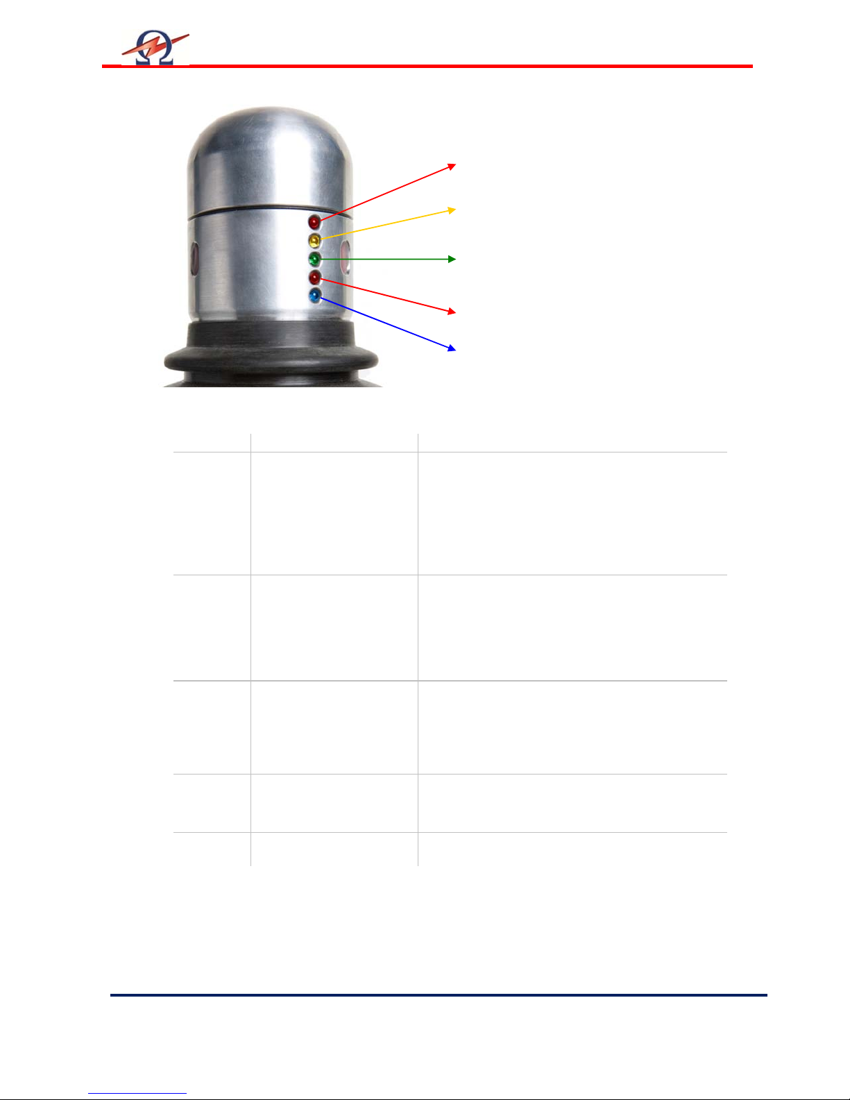
LED 1
– High Limit TD
LED 2 – Medium Limit TD
ED 3 – Low Limit TD
L
LED 4 – Battery Low
LED 5 – TD30 Status
LED Test during Startup
After Power On and during system startup/wake mode the TD unit performs a LED test to make
sure that all of the LED signals work and performs a quick self check
LED 1 Signal High TD
(RED)
LED 2 Signal Medium TD
(YELLOW)
LED 3 Signal Low TD
(GREEN)
LED 4 Signal Battery Low
(RED)
LED 5 Signal Status (BLUE) Flashing status signal showing active operation
A flashing signal here indicates a TD level that
is higher than the HIGH TD setting. If setup
correctly, this will normally indicate a poor TD
result. Flashing will occur simultaneously with
the status LED signal. The TD HIGH limit can
be set using the TD ControlCenter PC
Software.
A flashing signal here indicates a TD level that
is lower than the HIGH limit and higher than the
LOW limit. If setup correctly, this will normally
indicate a mediocre (medium) condition. The
limits of the TD value can be set using the TD
ControlCenter PC Software.
A flashing signal here indicates a TD level that
is lower than the LOW limit. If setup correctly,
this will normally indicate a good TD result. The
limit of the TD value can be set using the TD
ControlCenter PC Software.
Battery Low signal. Permanently ON if battery
voltage drops below critical limit. In battery
condition is OK then this light will not be ON.
Page 16
User Manual
Rev 1.4
Page
16 HV Diagnostics
Bluetooth
Information
Laptop
HVA
TD
30
Unshielded
Jumper
Corona Balls
Cable
High Voltage
Ground Cable
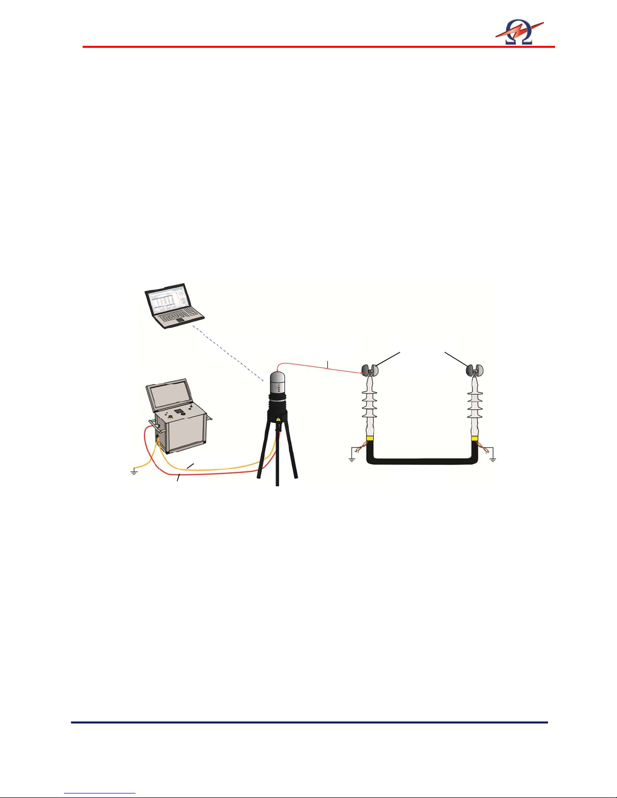
8 Connecting up the TD30 Instrument
Safe operation requires strict adherence to the recommended grounding procedures. The TD
measurement system hook-up to a cable or other electrical apparatus requires three
connections. It is important that these connections are made correctly, securely and in the
correct sequence. The TD30 is a measurement device and it and the DUT (Device under
Test) are energized by the HVA VLF high voltage power source. The TD30 does not itself
generate any High Voltage, but it does operate at the voltage applied to it by the HVA HV
power supply. Therefore, always treat the TD30 as being at the same voltage potential as the
HVA30 power supply “feeding” it. In addition, make sure that all safety precautions and
requirements are adhered to for the HVA30 test instrument – see HVA30 instruction manual.
Connection Diagram
Shielded Cable
The Ground Cable of the TD30 should be connected to the station ground (or to the HVA as
long as the HVA is grounded). In the case of a cable, this can be the concentric neutral / ground
shield / ground wire. The cable ground must be connected to the station ground for testing
purposes and SHOULD NOT be isolated from ground.
The HV Test Lead is a coaxial conductor made up of the center high voltage conductor and an
outside Shield Return that should remain at ground potential. The return shield is internally
connected to ground in the HVA via this HV plug and a separately grounded connection inside
of the TD system. Connect the HV Test lead of the TD30 to the HVA test instrument by
screwing in the HV plug. Make sure the plug is securely screwed into the HV socket and then
connect the TD30 system to the DUT using one of the versatile connectors. The connection of
the TD30 system to the DUT should be the last connection made before a test is commenced
and it should be the first one removed after a test has been performed and it should be
independently verified that there is no longer voltage present at the TD30.
from Tan Delta
“Yoyos”
(DUT)
Page 17

User Manual
HV Diagnostics
Page
17 Rev 1.4
9 Software TD ControlCenter
The TD system is delivered with a set of Windows based software tools that are packaged
into a software package called the TD ControlCenter. This software connects, records,
analyses and reports the test results from the TD30 test instrument.
Before doing any TD measurements, please make sure the PC or Notebook that you are
using is correctly setup and configured for Bluetooth® communication and has the
necessary hardware installed. A Bluetooth dongle is supplied with the TD system and this
can be installed by the user into the USB port of a computer. However, some PC’s and
Handhelds come with integrated built-in Bluetooth® capability and the supplied Bluetooth®
Dongle with the TD30 will normally not be required under these circumstances. In case
where Bluetooth® is already available or integrated into a PC, follow the user manual for
that device to correctly configure the Bluetooth® for communication purposes.
See also the “TD System Bluetooth Setup Manual”
For Bluetooth® connection setup using the supplied Bluetooth® dongle – please refer to
Appendix A.
Page 18
User Manual
Rev 1.4
Page
18 HV Diagnostics
1
3
4
5
7
8 9
11
12
TD ControlCenter Main Screen
2
6
10
Page 19

User Manual
HV Diagnostics
Page
19 Rev 1.4
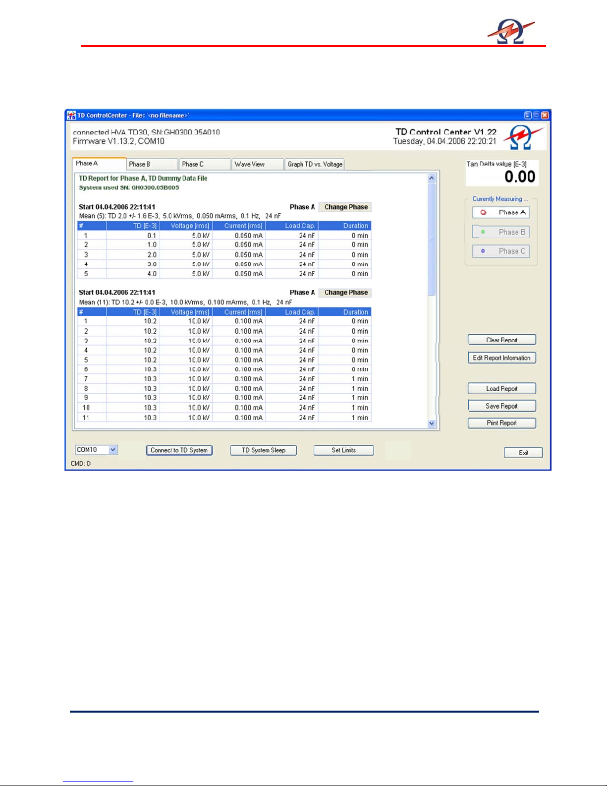
Description of Elements of the Main Screen:
1. System Information, Title Bar
The Title Bar shows connection status information like the serial of the TD system that is paired
to the current PC, the Battery Status information if a low signal if detected. A battery Low status
will also be visible on the battery status LED present on the TD30 (see above).
2. Information Selection Tabs
Use these Tabs to switch between the various information you want to view.
Phase A-C: Show detailed TD measurement information of Phase A or B or C.
If the corresponding Phase under “Currently Measured” (see element 12) is
selected all new measurements will automatically be inserted under the selected
tab.
Wave View: If a measurement is in progress, this tab shows a slightly delayed real-time
display of the data acquired by the TD measurement system. Voltage and
Current are shown. These values are not to scale. The graph is updated after
each finished waveform period.
Graph TD vs. Voltage:
Graphical display of the TD test results as a function of applied voltage. The
values of all three phases can be viewed and compared. The diagram is
completely auto-scaling and extracts the mean TD value from the most recent
voltage block for a particular phase.
3. Current TD Value
This field shows the currently measured TD value or the last value if measurement has stopped.
Helpful if not in Phase-View, so the current TD value can always be observed.
4. Report Phase Detail
Each Phase Measurement Report consists of header which includes the TD30 serial number it
was acquired from.
5. Report Block Header
For every detected voltage change during measurement the system automatically creates a
new block in the corresponding Phase Tab. Each Block starts with a header, which gives
information like the Start Time of the measurement and the updated mean values of this block.
The “Change Phase” Button enables the user to move a selected block to another Phase or to
completely remove it from the Report. This is useful if phase test data was mistakenly recorded
under the incorrect phase number. This can happen if the user starts a measurement under one
phase but does not change the “Currently Measured Phase Selection” (see below).
6. Report Block Measurements
This grid shows the detailed individual test measurements for each distinct voltage. Each
column is described with units in the grid header row.
7. Report Block Measurements Sequence
This next set of TD test measurements at the next successive applied test voltage.
Page 20

User Manual
Rev 1.4
Page
20 HV Diagnostics
8. Communication Port Selection
During the Bluetooth communication setup on a PC, the user is advised to use a specific serial
COM-Port for the outgoing communication port from the PC/Laptop to the corresponding active
TD System.
Use this selection box to set the corresponding Port-Number. This selection is remembered and
has only to be entered once for each TD System and PC pairing. If one computer is used to
communicate with more than one TD System, the computer assigns each TD unit a port
number. The ControlCenter shows the Serial Number of the currently connected TD System in
the Title Bar.
9. TD System Management Functions
Connect to TD System Use this button to connect to a TD System once you have
selected the correct Port Number. If the communication Port is
set correctly and the TD System is switched on (not in Power
Save Mode) then the connection will be established within 5
seconds. The ControlCenter shows the connection status in the
Title Bar.
TD System Sleep Places the connected TD System into Power Save Mode.
This is useful if the TD30 is not going to be used for TD
measurements for some extended period of time and the user
wants to conserve battery life.
If the TD30 system has entered a Power Save “Sleep” Mode and
you need to “reawaken” the TD30 for further TD measurements,
this can be done in 2 ways depending on the users requirements.
Firstly by re-applying high voltage (>1kV) from the HV Source
taken the necessary safety precautions OR secondly by
switching off the TD30 (main on/off switch) for about 2 minutes
and then turning the TD30 back on again. Please note that it will
also be necessary to re-click the “Connect to TD System” Button
after this process to re-establish the communication “pairing”
again.
Set Limits Use this function to set the Limits for the 3 TD Value Range
Signal LED’s on the TD unit. An upper (high) and a lower (low)
limit can be set if a connection is established. This in effect sets
up a low (good), medium and high (poor) range of TD limits. For
XLPE cables for example these TD limits can be set as follows:
TD LOW set to 1.2 (E-3)
TD High set to 2.2 (E-3).
Please note that it may be necessary to reset the TD30 system
for the limits to take effect. This can be done by turning OFF and
ON the main switch on the TD30. These values are stored in
non-volatile memory in the TD30 until they are changed by the
user again.
This function allows the TD30 system to be used as a standalone
device allowing a quick and easy indication of a TD range without
necessarily having a PC available.
Page 21
User Manual
HV Diagnostics
Page
21 Rev 1.4
10 Test Report File Functions – Load, Save, Print …
Use these buttons to Load, Save and Print a test report.
The Print function can also be used to create PDF document reports if a PDF Writer or a similar
PDF Printer Driver is installed.
11 Report Specific Functions
Clear Report
Clears the current active report test data. Be sure to save your test data before you clear a test
report. This function is useful if you want to start a new test and want to “clean” test sheet.
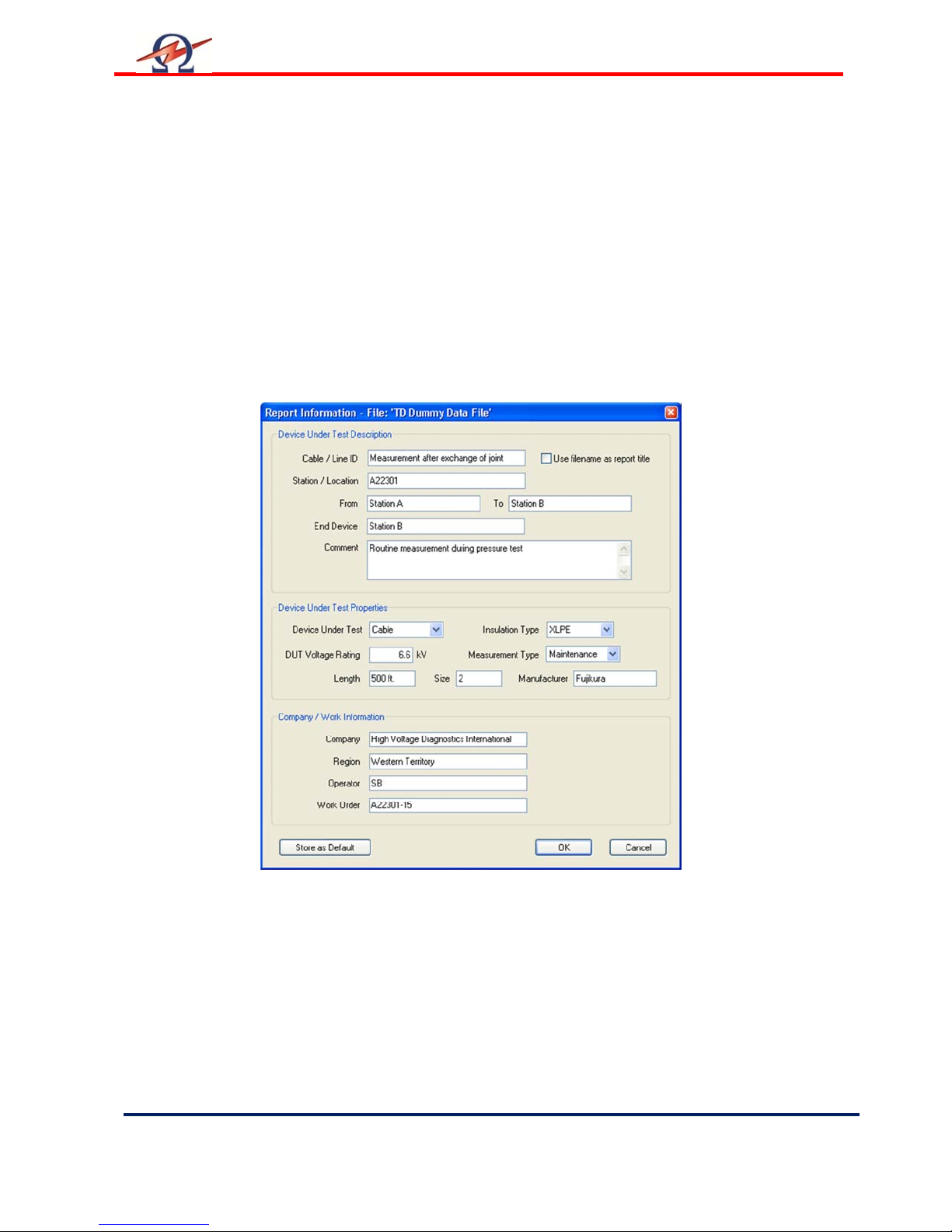
Edit Report Information
This Form enables the user to save detailed information with the report data.
A Cable/Line ID (if cable as DUT is selected)
The user can enter a unique identifier for the Device Under Test (DUT).
This Text will also be used (by default) as the title for this Report on the Summary
and Printout.
B Store As Default
The user can store certain fields that are not likely to change from one test to
another as default start-up fields. These fields are then easily and automatically
inserted into any new test reports.
Fields stored: Station, Company, Region and Operator
Page 22

User Manual
Rev 1.4
Page
22 HV Diagnostics
C Use filename as report title
If this box is checked, the report filename will be used as the report title instead of
the Cable/Line ID field.
12 Currently Measuring…… Phase Selection
The phase that is currently being tested by the TD30 needs to be selected.
All new measurement data will be put into the corresponding report phase section (tab).
If the operator changes the phase during an active TD measurement, the change will only occur
when the current TD voltage block is finished to avoid splitting up of the respective TD
measurement data block. The block “under the wrong” phase tab can then be moved to the
correct phase section using the “Change Phase” button in the block header as a later stage.
Page 23
User Manual
HV Diagnostics
Page
23 Rev 1.4
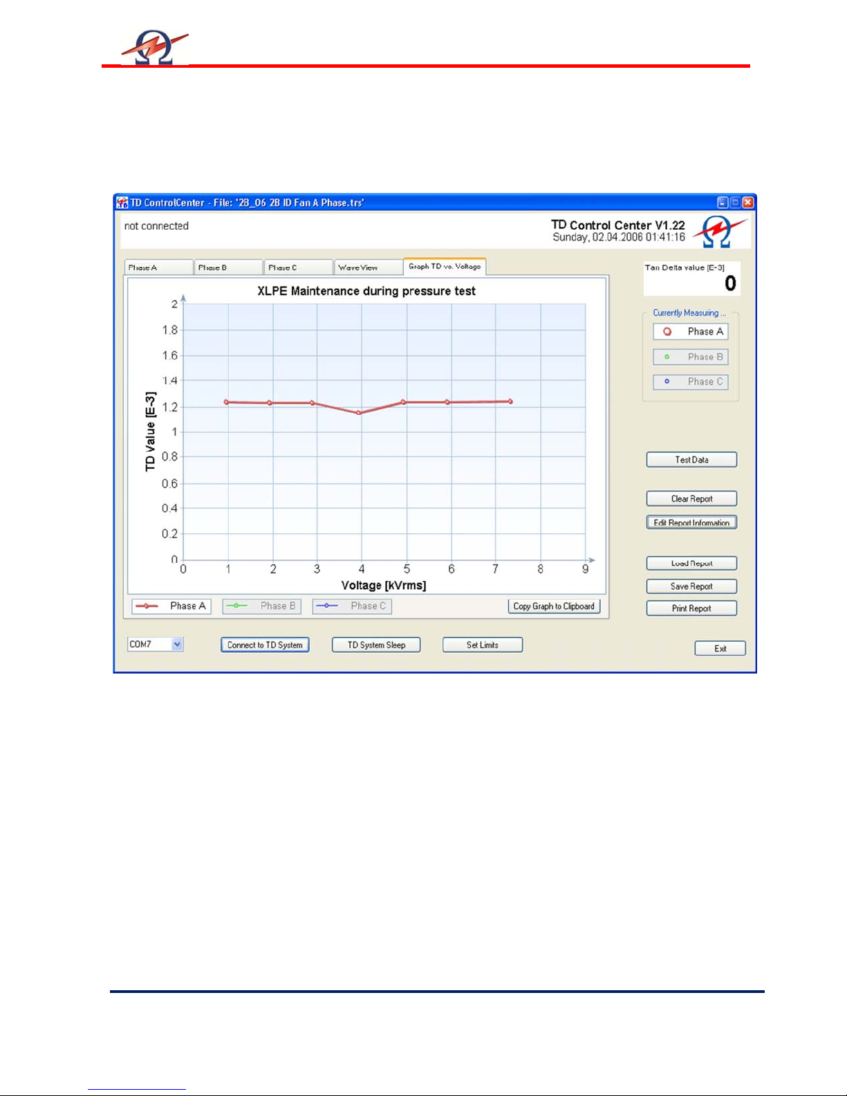
Graphical View / Diagram
This screen provides a graphical diagram of the Mean TD measurement data versus the applied
test voltage.
The values of all three phases can be viewed and compared. The graph automatically scales
and draws the mean TD values for each voltage block.
1 Phase Selection for Diagram View
Toggle ON/OFF the various phases to display / block out the relevant phase information.
2 Copy Graph to Clipboard
Use this function to make a copy the currently shown TD diagram into the Windows Clipboard. It
can then be easily put into many other applications (like Word, Excel) by selecting Paste in the
target program.
Page 24
User Manual
Rev 1.4
Page
24 HV Diagnostics
10 Instrument Care
Cleaning
Electric Shock Hazard!
Only clean the instrument when turned off!
After use, clean the TD head and Cable connection points.
DANGER
Storage
CAUTION
Instrument Damage
Do not store the TD outdoors!
Keep the TD away from liquids!
TD should be stored indoors in the following environ
• Temperature: -25°C to 70°C (-13°F to 158°F)
• Humidity: 5-85% non-condensing
mental conditions:
Maintenance and Repairs
Authorized personnel only!
Repairs and maintenance should only be performed by authorized HV
Diagnostics’ personnel.
One yearly inspection by authorized HV Diagnostics’ personnel is
recommended.
NOTICE
Page 25

User Manual
HV Diagnostics
Page
25 Rev 1.4
Appendix A: Software Installation Procedure ‘TD
ControlCenter’
A CD containing the TD Control Center Software for Windows 2000®, Windows XP®, or
Windows 7® based PCs is shipped with the TD Measurement System.
Prior to installation close all running applications to avoid influence.
To install put the CD into a CD/DVD Drive – the Install Wizard appears automatically. Follow the
steps as described in the Installation Wizard to perform the installation. For easy installation
leave the installation path as indicated
To start the TD ControlCenter after Installation, double click the new icon on your desktop or
use the new Start menu entry under the “HVA ControlCenter”.
Setup does not start automatically
In some cases - depending on the settings of Windows - Setup does not start automatically.
If so follow these steps:
• Locate and double click the “My Computer” icon on the Windows Desktop
• A Window with your local Hard-Drives and CD/DVD-Drives shows up
• Double click the symbol of the drive where you have inserted the CD
• If Setup starts now, proceed as described above
• Otherwise a new window has opened and shows the content of the CD
• Locate and point to the folder “Setup” on the CD and double click
• The content of this folder is now shown, locate the file “Setup TD ControlCenter” and
double click (this file can also be named “Setup TD ControlCenter.exe” or just
“Setup.exe”). Setup will start now proceed as described above.
Page 26

User Manual
Rev 1.4
Page
26 HV Diagnostics
Appendix B: Bluetooth® Setup and Config
Procedure
A Bluetooth USB dongle is shipped with every TD30 system. This dongle is tested to work with
the TD unit and can be used if your Computer/Notebook has no built in integrated Bluetooth
Hardware. Since there are various ways to use and configure Bluetooth under Windows
operating systems, the following procedures are provided to setup and use Bluetooth wireless
TD measurement system. You will need Administrator Privileges to install the drivers on certain
secure networks.
Communication Parameters for Bluetooth Setup (Advanced Users)
• Bluetooth v1.1 compliant
• Serial Port Profile, only this profile and the corresponding
outbound COM port needed
• COM1 to COM99 are supported
• Secure and unsecure communication and pairing supported
• Passkey used is “welcome”, lowercase, (for pairing this is also the PIN-code)
To install the communication three steps have to be done
• Step 1: Installation of Bluetooth driver support on your computer (if not already built-in)
• Step 2: Configure Bluetooth support (Initial usage, only has to be done once)
• Step 3-A/B: Setting up the TD Communication Port
A: With use of External Dongle or B: Windows Supported Hardware
There are 2 different ways to set up a communication port, one is with Windows directly
supported, one is using the external dongle. See below which procedure is to use with
your computer.
Check Bluetooth Hardware
First check if your computer has a built in Bluetooth communications hardware like most of the
newer Notebooks have. Normally they are then already configured to use Bluetooth.
In this case you will not need to use the external USB dongle nor should you install the
Bluetooth driver CD supplied.
If you are not sure if Bluetooth is installed and running please check with your system
administrator to verify if Bluetooth is supported on your computer system.
Installed drivers show a white on blue B-Icon in the system tray on the right bottom side of the
desktop (Taskbar). Some Notebooks have separate pushbuttons to switch it on/off.
If Bluetooth is already supported you can go directly to Step 3-B Setting up TD
Communication (Windows supported). If your system uses a different driver as shown in this
manual use the above mentioned parameters to set up Communication.
Step 1 Installation of Bluetooth support on your computer
If your computer does not have a built in or existing Bluetooth Hardware you can use the
Bluetooth Dongle and CD which is shipped with your TD System. This dongle has been tested
to work with the TD unit and has a range of approximately 50 feet / 15 meters.
DO NOT INSTALL THE BLUE TOOTH DONGLE BEFORE YOU INSTALLING THE
DRIVERS AS DESCRIBED BELOW.
Page 27
User Manual
HV Diagnostics
Page
27 Rev 1.4
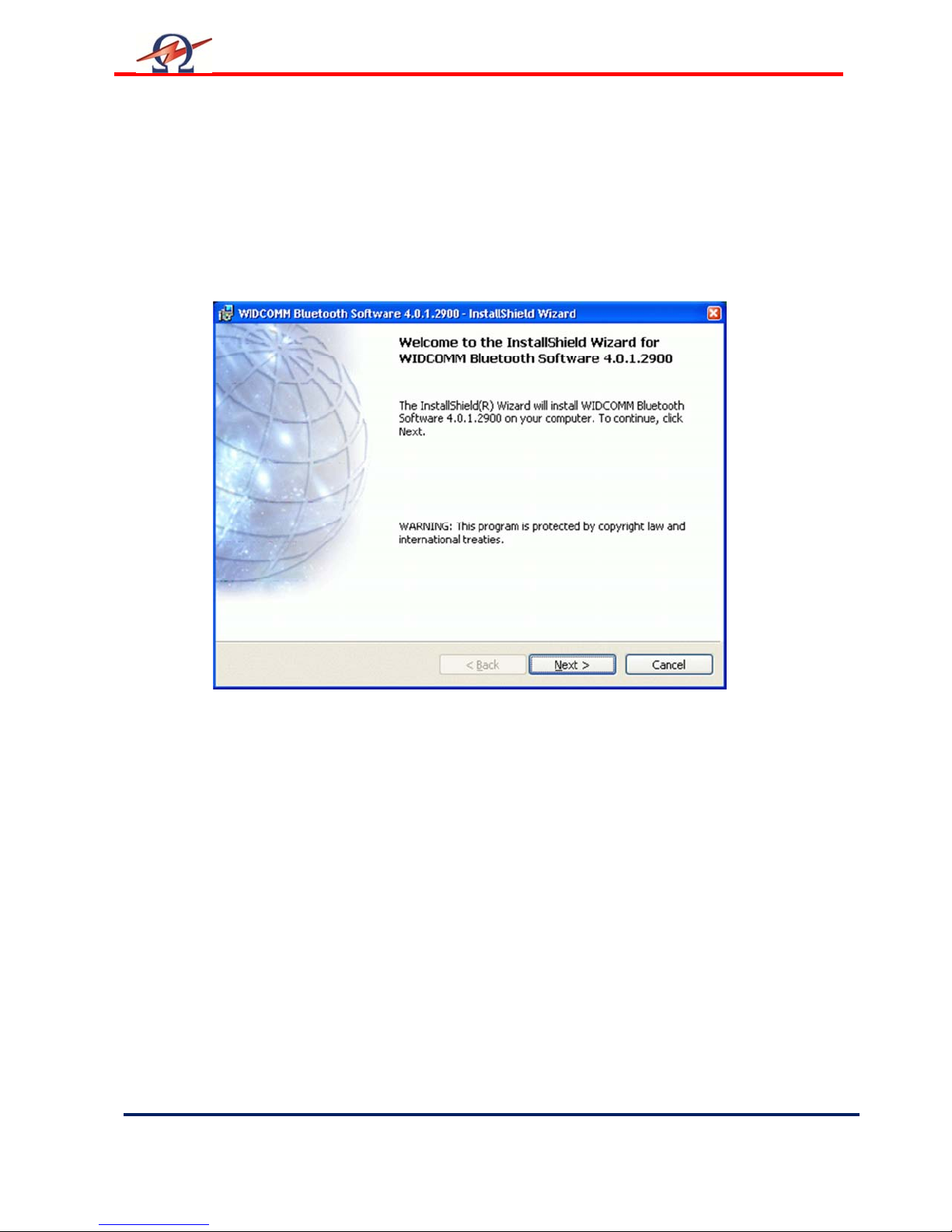
Start Installation
Start the installation process by inserting the driver CD supplied.
The Setup should start automatically, if not locate the CD/DVD drive on “My Computer” and
start Setup.exe in the driver folder.
Due to possible technologically changes in drivers and the Windows operating system, certain
messages shown below may vary slightly to what you may find on your computer.
Driver Setup Start Screen
Page 28
User Manual
Rev 1.4
Page
28 HV Diagnostics
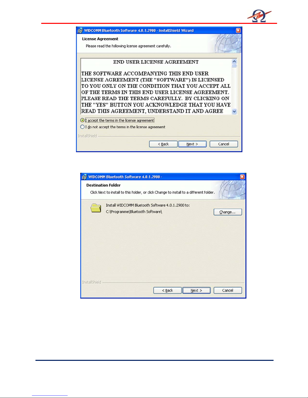
Choose Driver Software Destination. We suggest to use the defaults.
Accept License agreement
Page 29
User Manual
HV Diagnostics
Page
29 Rev 1.4
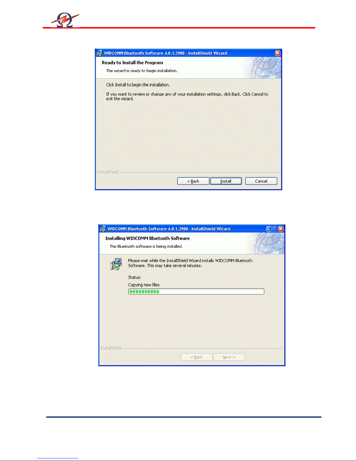
Begin Installation
Installation has started
Page 30
User Manual
Rev 1.4
Page
30 HV Diagnostics
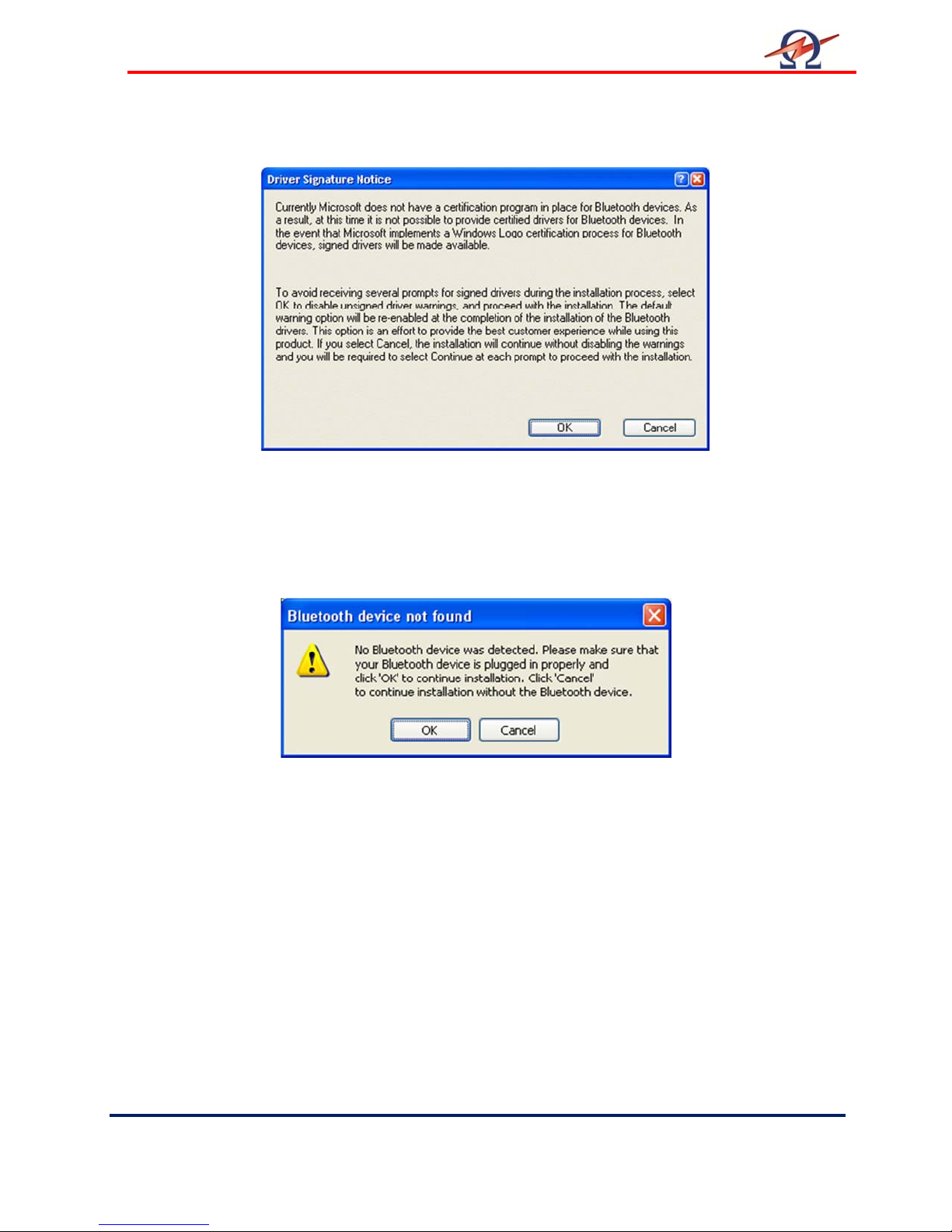
Press OK to accept this driver
The driver now needs to have the Bluetooth dongle inserted.
Plug the dongle into a free USB port. The windows Hardware Installation
will now run and some further information windows will appear.
Please wait until the Hardware Detection has finished.
This screen will then disappear automatically.
Page 31
User Manual
HV Diagnostics
Page
31 Rev 1.4
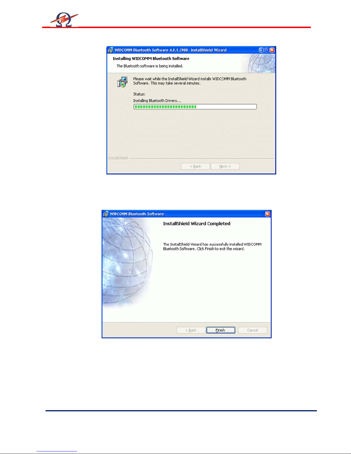
Installation of Bluetooth support on your Computer. Other information messages may appear.
Please wait until the Installation completes.
Installation of Bluetooth support finished.
The above mentioned white on Blue “B”-Bluetooth icon now
appears in the system tray.
Page 32
User Manual
Rev 1.4
Page
32 HV Diagnostics
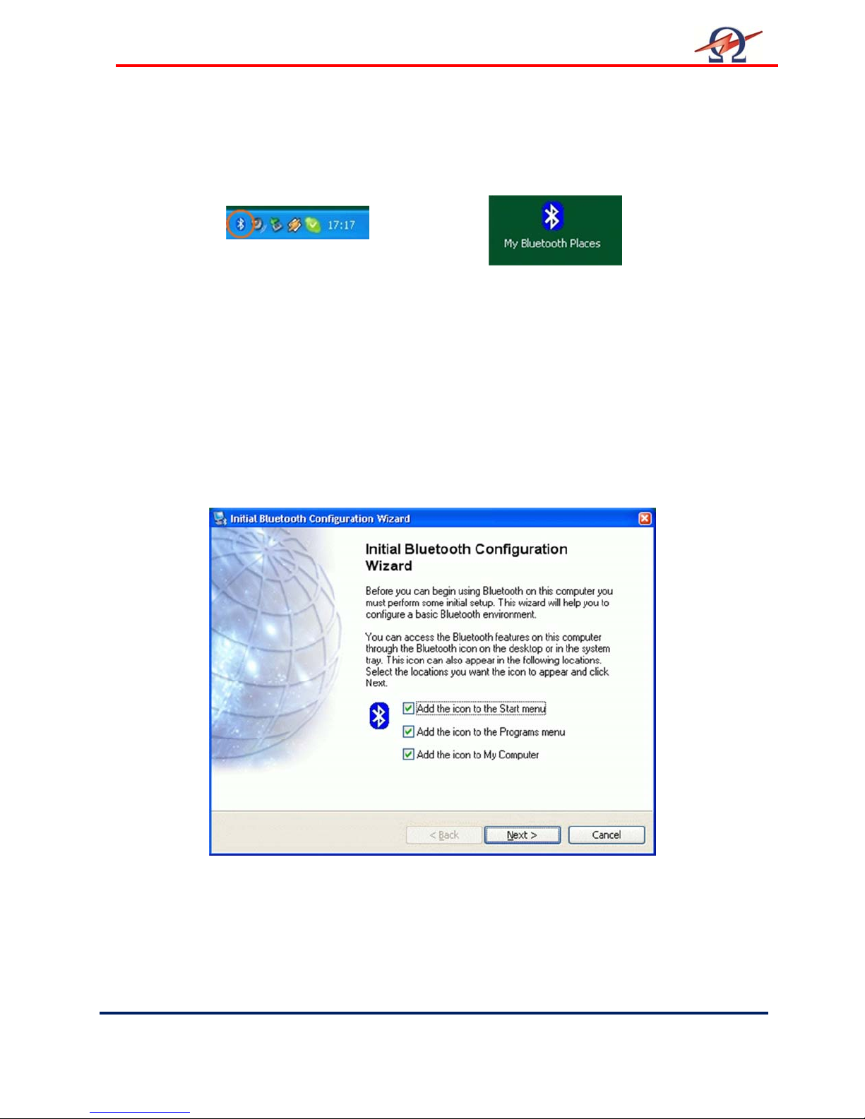
Step 2 Configure Bluetooth Support (First Time Users)
After successful driver installation a white on blue Bluetooth icon appears in the system tray on
the right bottom side of your desktop and a new Icon “My Bluetooth Places” appears on your
desktop:
Configure Bluetooth Support using external dongle
Please follow these instruction to set up a communication port to the TD system if you are using
the external dongle with the above mentioned driver (not windows built in support).
First usage configuration
After the new installation of the Bluetooth support on your computer, you have to configure the
type of service your computer uses.
Double click on the Bluetooth icon in the system tray or the “My Bluetooth Places” icon on your
desktop to bring up the configuration wizard:
Initial Bluetooth configuration (only has to be done once)
Page 33
User Manual
HV Diagnostics
Page
33 Rev 1.4
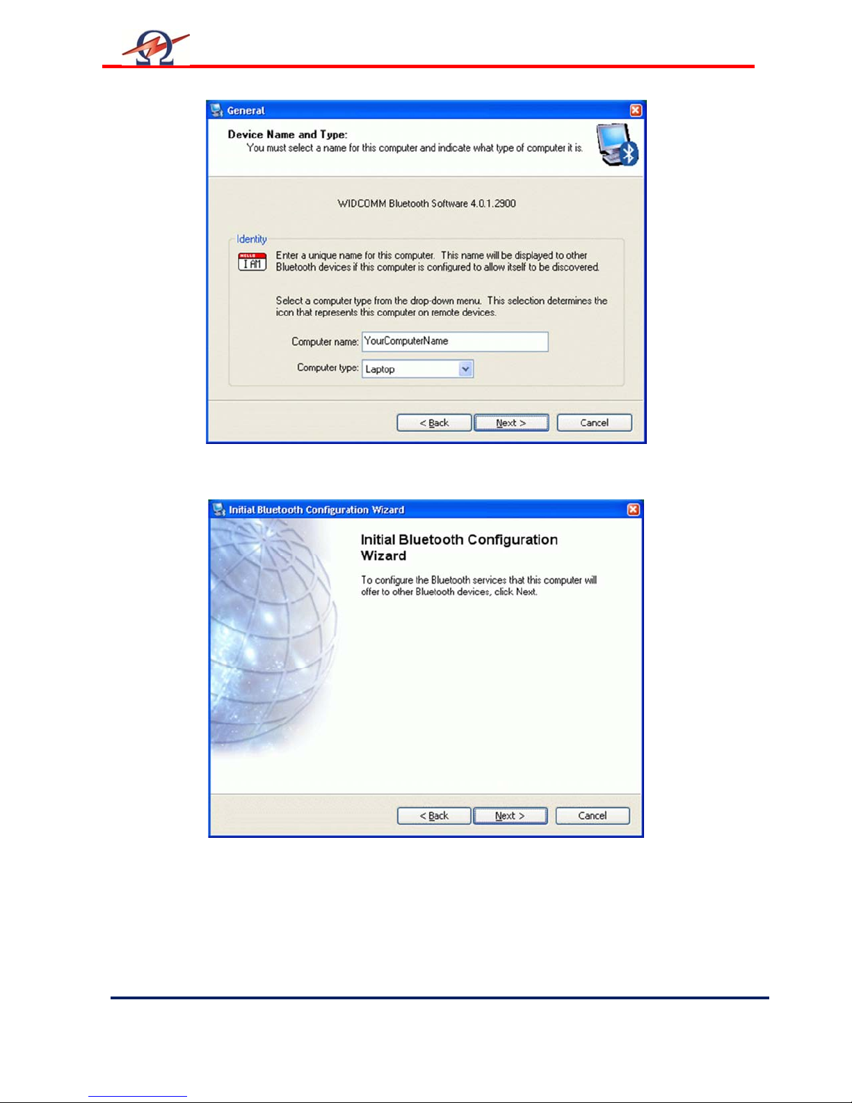
Type in the name and type of your computer
Start Configuration
Page 34
User Manual
Rev 1.4
Page
34 HV Diagnostics
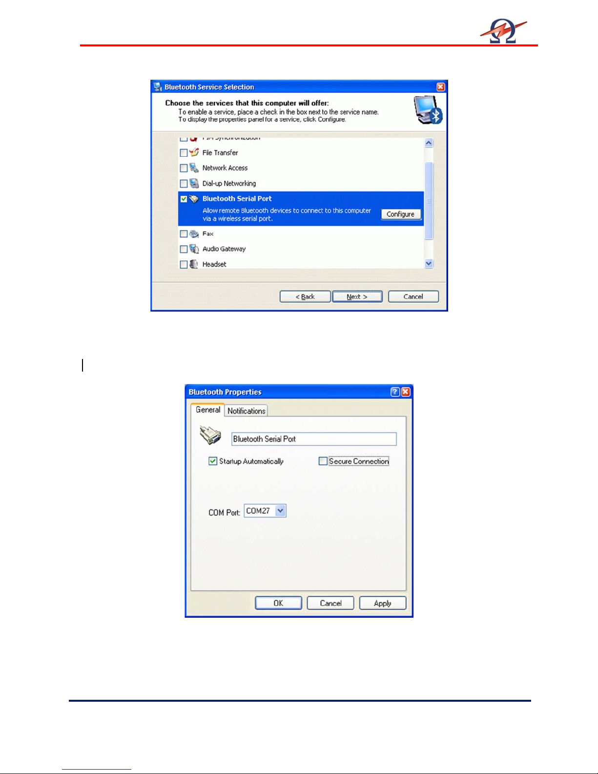
If you only want to set up for TD communication you can uncheck all
Check or uncheck those Bluetooth services you want to use.
except the “Bluetooth Serial Port” which is all the TD30 requires.
Bluetooth Serial Port Configuration. Leave as suggested. Take note of the serial port number.
Page 35
User Manual
HV Diagnostics
Page
35 Rev 1.4
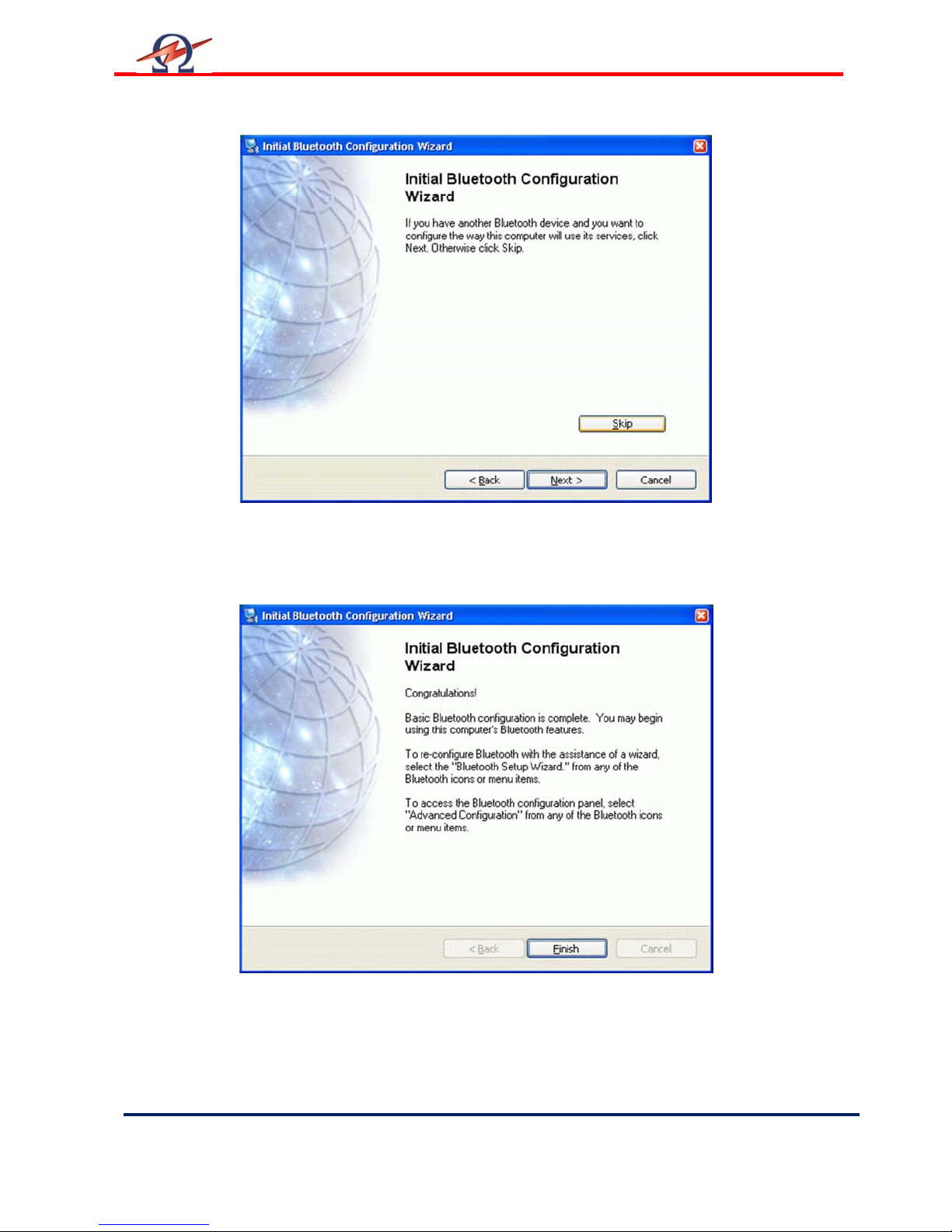
Press Skip to tell the system that you will connect to the TD system at a later stage.
Finished Initial Setup of Bluetooth Support.
Page 36
User Manual
Rev 1.4
Page
36 HV Diagnostics
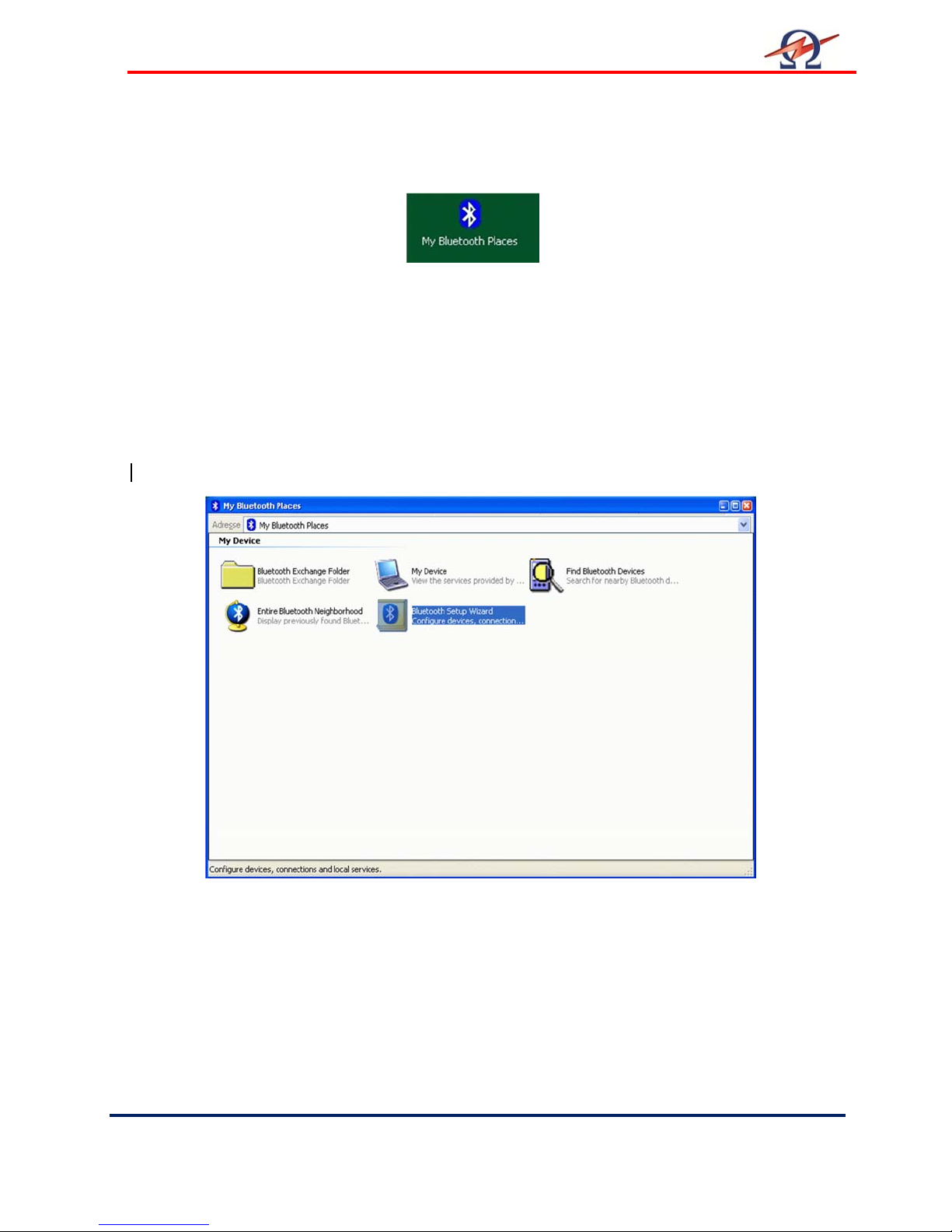
Step 3-A: Setting up a TD Communication Port (External Dongle)
After installation and configuration of the Bluetooth drivers and hardware dongle, an icon called
“My Bluetooth Places” gives you access to all Bluetooth specific properties and configurations.
All configured devices are listed under the “My Bluetooth Places”.
Switch on the TD system
Before connecting, reset the TD System by switching the main power switch off and then ON
again.
Make sure the TD system is within 50 foot / 15 meters of the connecting computer. Since the
Bluetooth RF signals can be affected by other wireless systems and obstructions such as
WLAN or other RF devices, try moving the TD system closer to your computer if you cannot get
a “pairing” connection from following the procedure below.
Setup the Communication Port to connect to the TD30
Start to set up a communication port to the TD system by double-clicking on the “My Bluetooth
Places” icon.
My Bluetooth Places:
Select Bluetooth Setup Wizard to connect to TD system.
Page 37
User Manual
HV Diagnostics
Page
37 Rev 1.4
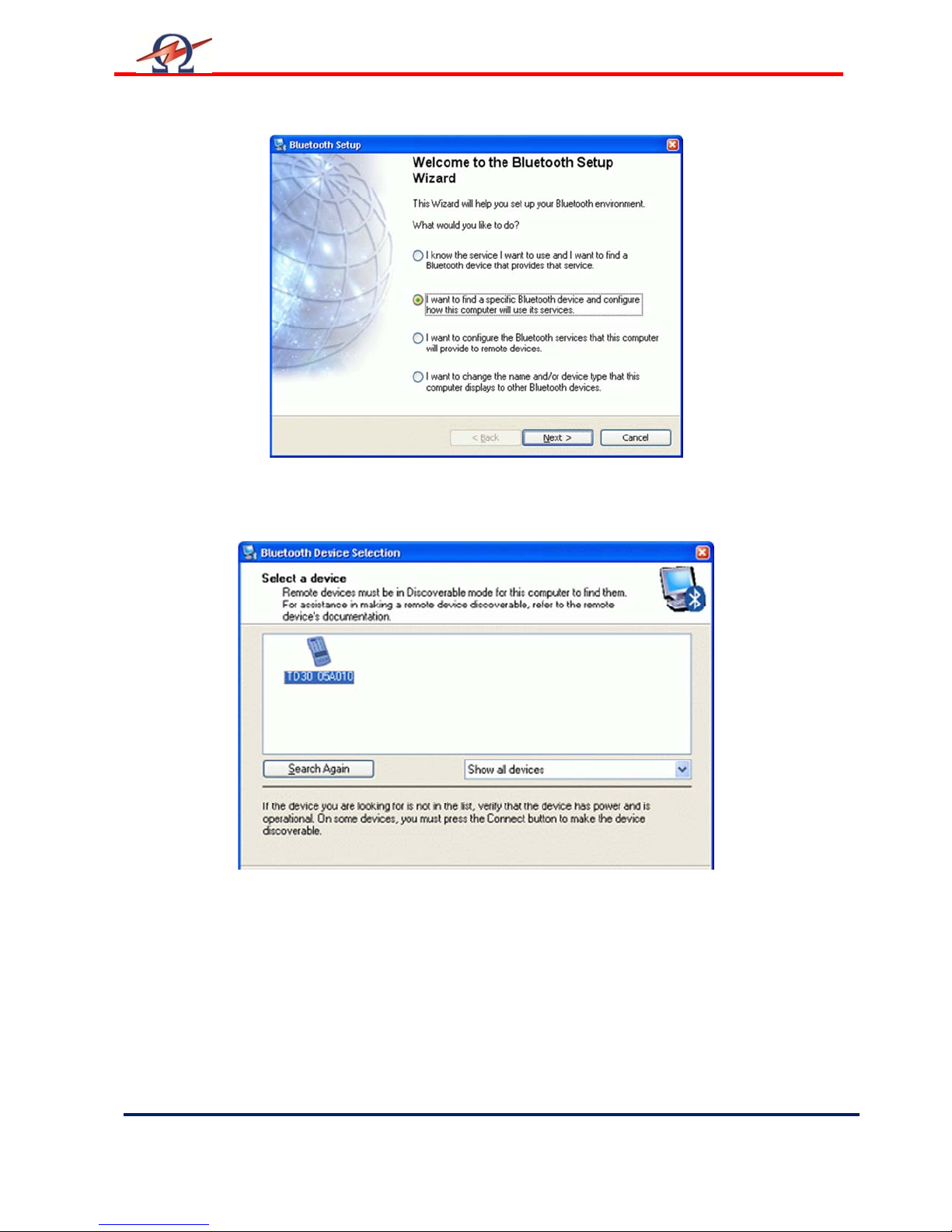
Select “I want to find a specific Bluetooth device …”
to find the TD system
TD systems are shown with the last 6 digits of the Serial number.
All available Bluetooth devices are listed.
Select the TD unit you want to connect to.
Page 38
User Manual
Rev 1.4
Page
38 HV Diagnostics
.
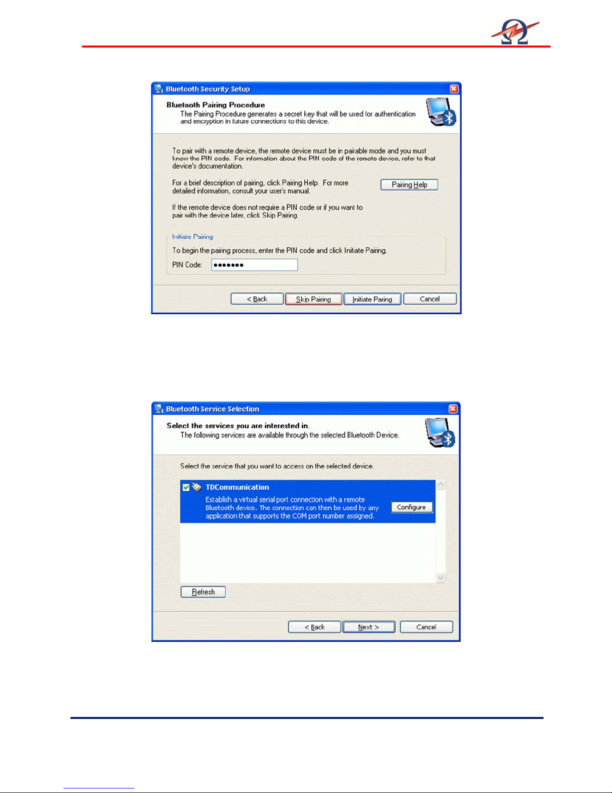
Pair the device. Type in the PIN code “welcome” and press “Initiate Pairing”.
A message “No Com port available” may be appear. Just quit with ok.
Check the “TDCommunication” service to use.
A message to configure the port will appear.
Page 39
User Manual
HV Diagnostics
Page
39 Rev 1.4
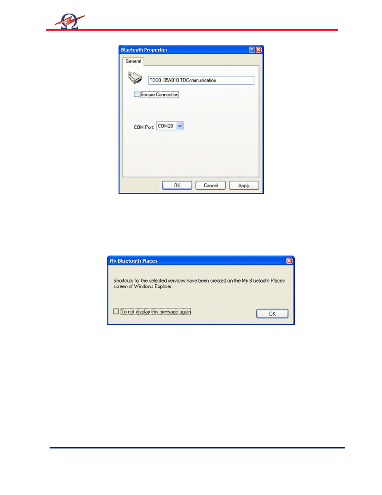
Leave default setting for this port. Make note of it.
You can use either Secure or Unsecured Connection.
Successful Setup of communication port!
Page 40
User Manual
Rev 1.4
Page
40 HV Diagnostics
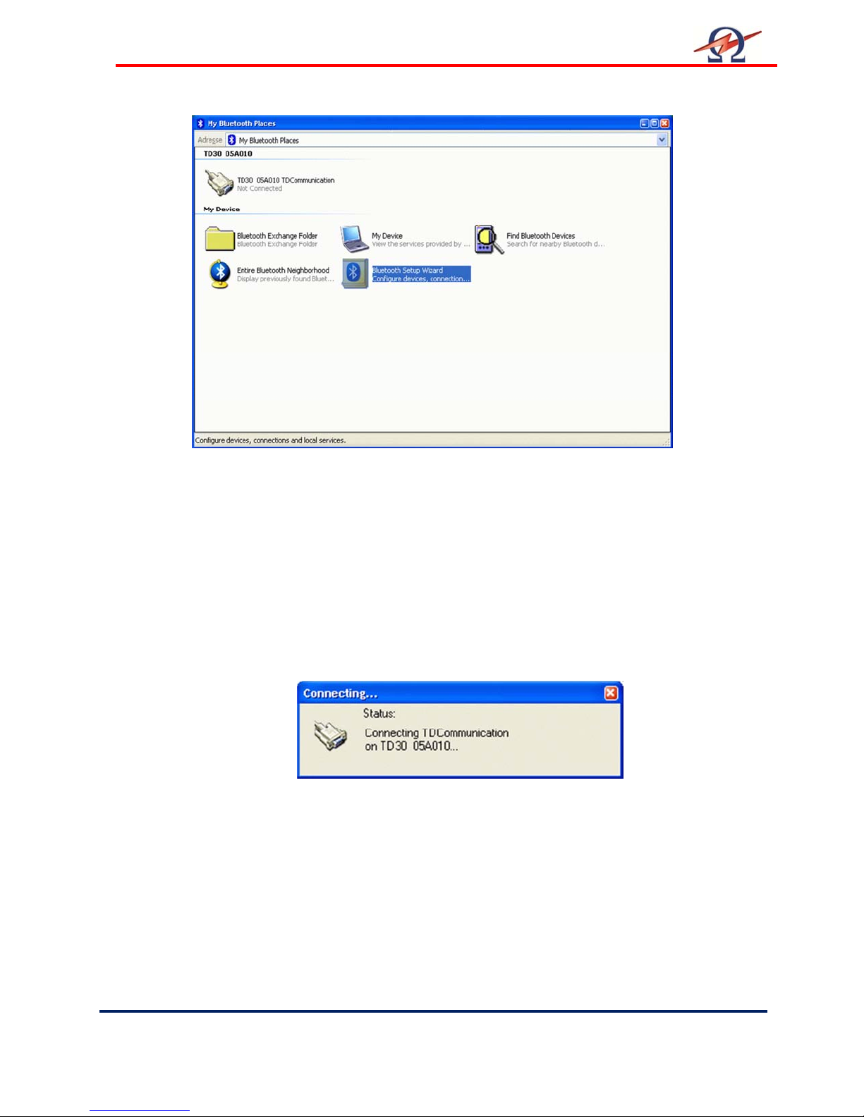
The TD system is now shown as an icon in
“My Bluetooth Places”
Initial Connection to the TD unit (Establish and Test connection)
To establish the connection and to fix the settings of the COM-port you have to perform a initial
connection to the TD unit. This is also verifies a correct setup.
Double click the TD System icon.
Connecting to the TD System
Page 41
User Manual
HV Diagnostics
Page
41 Rev 1.4
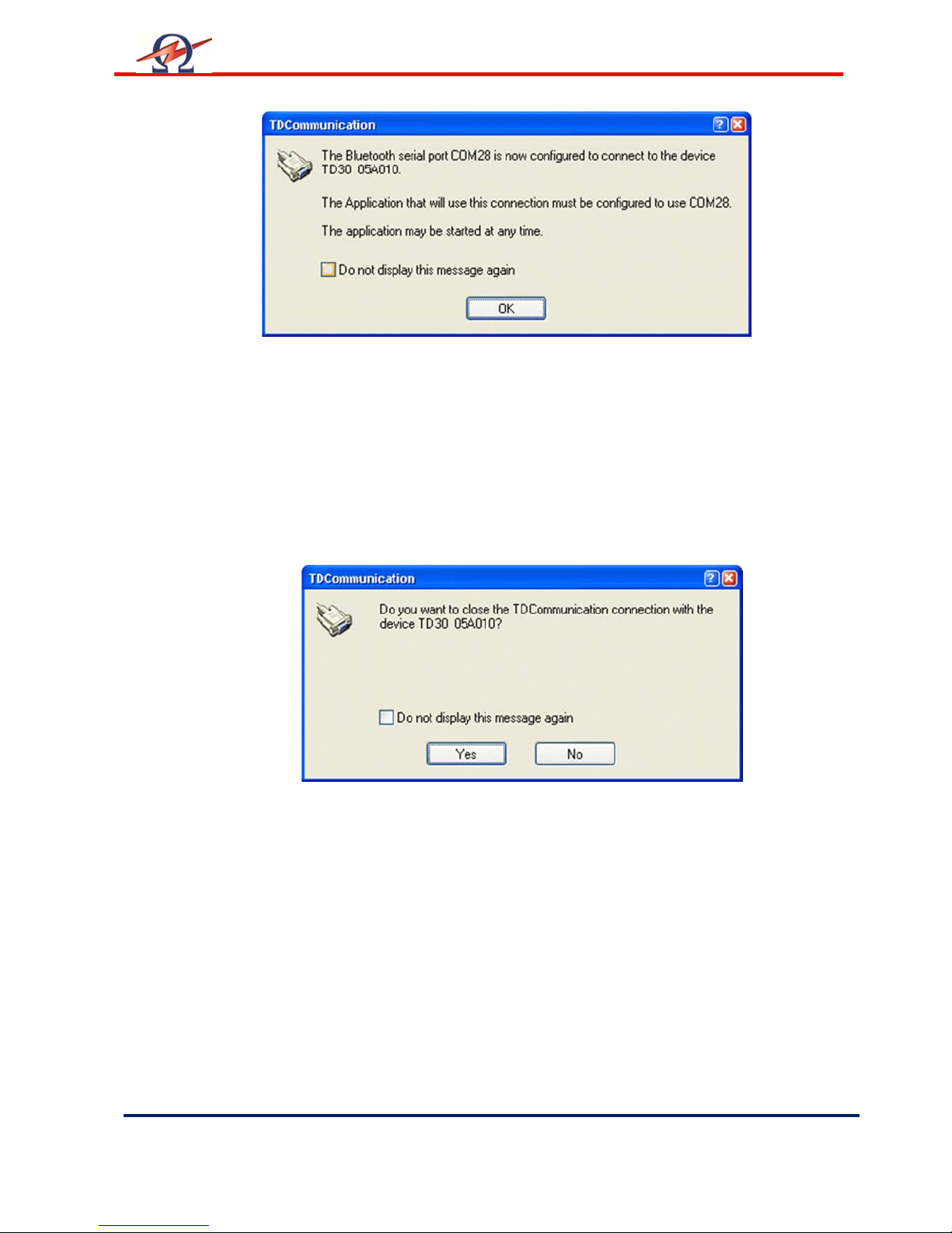
Established Connection!
Read the information and note the COM-Port Number.
This number is used by the TD ControlCenter to communicate with the TD unit.
You can use the 3rd page of the manual to write down this
Configuration number for later reference purposes.
Close (disconnect) the Test connection
Right click on the TD System icon and select Disconnect.
Disconnecting
It is also possible to switch off the TD system and the connection will automatically be closed.
The System is now configured and you can start working with the TD ControlCenter. You will
use the given COM-Port number to set in the ControlCenter and press the connect button.
Page 42
User Manual
Rev 1.4
Page
42 HV Diagnostics
Step 3-B: Setting up a TD Communication Port (Windows Supported)
If your Windows operating System already supports your Bluetooth Hardware you can use the
Windows Bluetooth System instead of a separate driver to set up the communication.
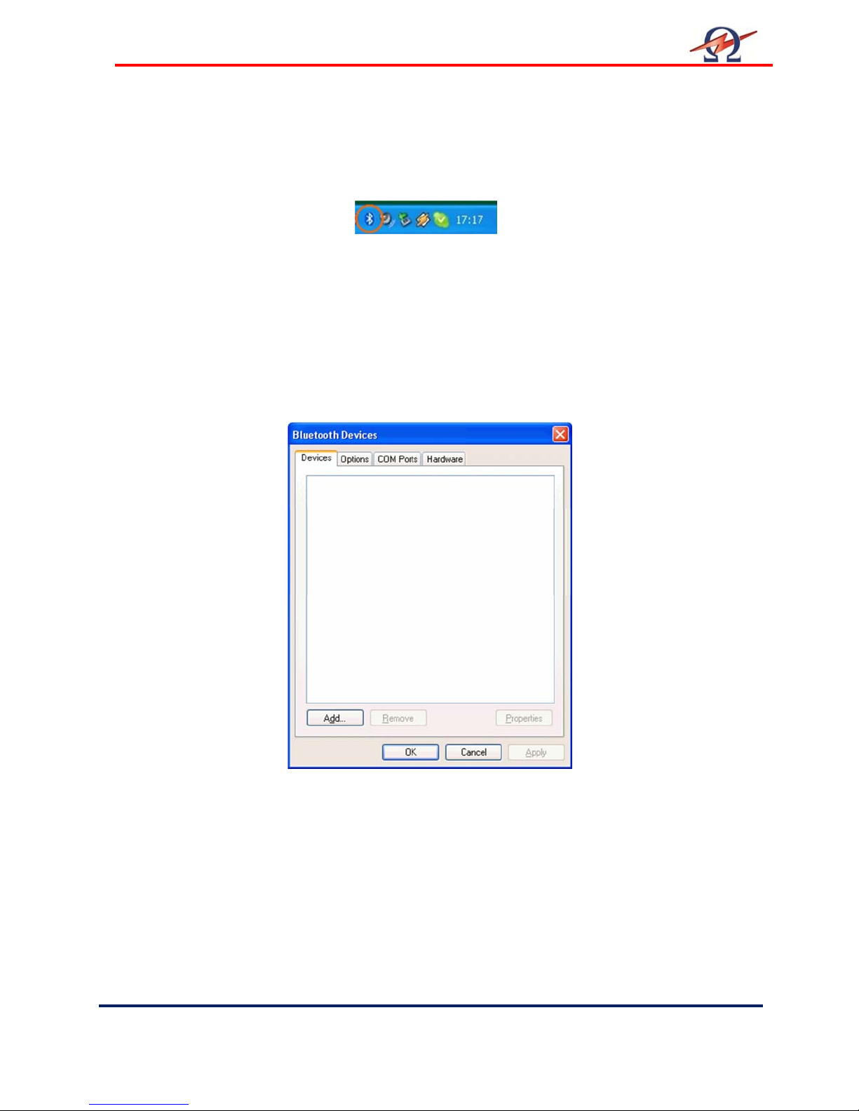
Windows shows you the Bluetooth icon in the System Tray on the right bottom side of your
desktop. This gives you access to all Bluetooth specific properties and configurations.
Switch on the TD system
Before connecting reset the TD System by switching the main power switch off and on.
Make sure the TD system is within the range of 50 feet / 15 meters to the computer. Internal
integrated Bluetooth devices often have closer working ranges than external. So you maybe
have to reduce the distance to get good connectivity.
Setup the Communication Port
Start to set up and allocate a communication port to the TD system by double-clicking on the
Bluetooth icon in the system tray.
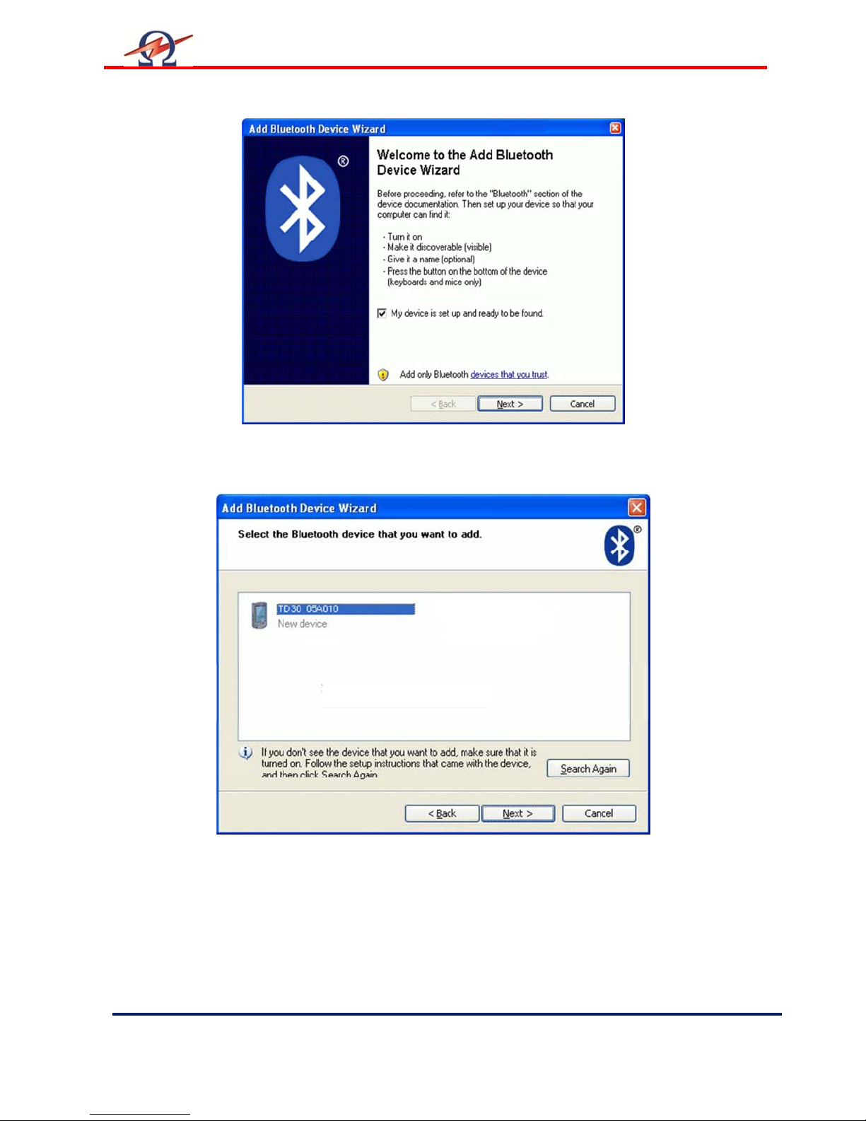
Bluetooth Devices, press Add to start
Page 43
User Manual
HV Diagnostics
Page
43 Rev 1.4
Check Device is switched on and ready to discover
All available Bluetooth devices are listed.
TD systems are shown with the last 6 digits of the Serial number.
Select the TD unit you want to connect to.
Page 44
User Manual
Rev 1.4
Page
44 HV Diagnostics
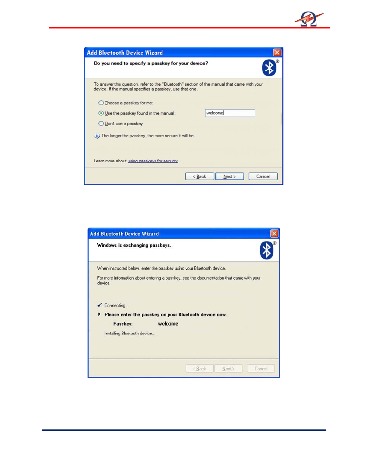
Select “Use Passkey from documentation” and enter
“welcome” to use as key
Windows connects to the TD System and installs the relevant drivers.
Page 45
User Manual
HV Diagnostics
Page
45 Rev 1.4
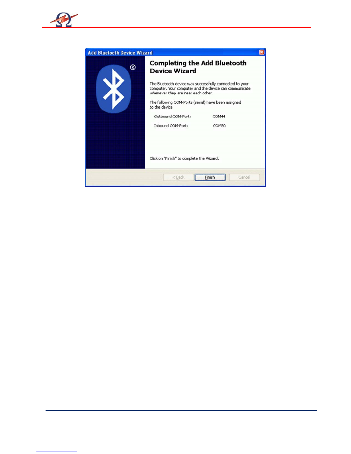
Read the information and note the “outgoing/outbound” COM-Port Number.
This number is used by the TD ControlCenter to communicate with the TD unit.
You can use the 3
Configuration Com Port number for later reference purposes.
rd
page of the manual to write down this
Page 46
User Manual
Rev 1.4
Page
46 HV Diagnostics
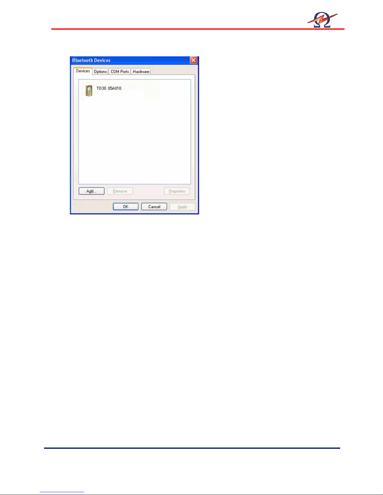
The System is now configured.
You can start working with the
TD ControlCenter.
Use the given COM-Port number in the TD
ControlCenter and press the connect button.
Page 47

User Manual
HV Diagnostics
Page
47 Rev 1.4
 Loading...