

HVAC Partners KGAPN43012SP Installation Instructions Manual
KGAPN43012SP
Installation Instructions
CERTIFIED
NOTE: Read the entire instruction manual before starting the
installation.
SAFETY CONSIDERATION
!
WARNING
FIRE, EXPLOSION, ELECTRICAL SHOCK, AND
CARBON MONOXIDE POISONING HAZARD
Failure to follow this warning could result in personal
injury or death.
This conversion kit shall be installed by a qualified service
agency in accordance with the manufacturer’s instructions
and all applicable codes and requirements of the authority
having jurisdiction. If the information in these instructions
is not followed exactly, a fire, explosion, or production of
carbon monoxide could result causing property damage,
personal injury, or loss of life. The qualified service agency
is responsible for the proper installation of this furnace with
this kit. The installation is not proper and complete until the
operation of the converted appliance is checked as specified
in the manufacturer’s instructions supplied with the kit.
G a s C onv e r si on Ki t P ropane --- t o --- N a t u r a l f o r
Two--- Stage Condensing and
Non---Condensing Gas Furnaces
personnel must perform all other operations. When working on
heating equipment, observe precautions in the literature, on tags,
and on labels attached to or shipped with the unit, and other
safety precautions that may apply.
Follow all safety codes. In the United States, follow all safety
codes including the current edition of the National Fuel Gas Code
(NFGC) NFPA No. 54/ANSI Z223.1. In Canada, refer to the
current edition of the National Standard of Canada, Natural Gas
and Propane Installation Codes (NSCNGPIC),
CAN/CSA--B149.1 and .2. Wear safety glasses and work gloves.
Have a fire extinguisher available during start--up, adjustment
steps, and service calls.
Recognize safety information. This is the safety--alert symbol
. When you see this symbol on the furnace and in instructions
or manuals, be alert to the potential for personal injury.
Understand the signal words DANGER, WARNING, CAUTION
and NOTE. The words DANGER, WARNING, and CAUTION
are used with the safety alert symbol. DANGER identifies the
most serious hazards which will result in severe personal injury or
death. WARNING signifies a hazard which could result in
personal injury or death. CAUTION is used to identify unsafe
practices which may result in minor personal injury or product
and property damage. NOTE is used to highlight suggestions
which will result in enhanced installation, reliability, or operation.
INTRODUCTION
!
WARNING
!
AVERTISSEMENT
LE FEU, L’EXPLOSION, CHOC ELECTRIQUE,
ET MONOXYDE DE CARBONE
EMPOISONNER
Cette trousse de conversion doit être installée par un servie
d’entretien qualifié, selon les instructions du fabricant et
selon toutes les exigences et tous les codes pertinents de
l’autorité compétente. Assurezvous de bien suivre les
instructions dans cette notice pour réduire au minimum le
risque d’incendie, d’explosion ou la production de
monoxyde de carbone pouvant causer des dommages
matériels, de blessure ou la mort. Le service d’entretien
qualifié est responsable de l’installation de cette trousse.
L’installation n’est pas adéquate ni complète tant que le bon
fonctionnement de l’appereil converti n’a pas été vérfié
selon les instructions du fabricant fornies avec la trousse.
Installing and servicing heating equipment can be hazardous due
to gas and electrical components. Only trained and qualified
personnel should install, repair, or service heating equipment.
Untrained personnel can perform basic maintenance functions
such as cleaning and replacing air filters. Trained service
FIRE, EXPLOSION, ELECTRICAL SHOCK AND
CARBON MONOXIDE POISONING HAZARD
Failure to follow instructions could result in personal injury,
death or property damage.
Improper installation, adjustment, alteration, service,
maintenance, or use can cause carbon monoxide poisoning,
explosion, fire, electrical shock, or other conditions, which
could result in personal injury or death. Consult your
distributor or branch for information or assistance. The
qualified installer or agency must use only
factory--authorized kits or accessories when servicing this
product.
!
WARNING
FIRE, EXPLOSION, ELECTRICAL SHOCK
HAZARD
Failure to follow this warning could result in personal
injury, death or property damage.
Gas supply MUST be shut off before disconnecting
electrical power and proceeding with conversion.
!
WARNING
ELECTRICAL SHOCK, FIRE OR EXPLOSION
HAZARD
Failure to follow this warning could result in personal
injury, death or property damage.
Before installing, modifying, or servicing system, main
electrical disconnect switch must be in the OFF position and
install a lockout tag. There may be more than one
disconnect switch. Lock out and tag switch with a suitable
warning label. Verify proper operation after servicing.
INSTALLATION
1. Set room thermostat to lowest setting or “OFF”.
2. Remove outer doors.
3. Disconnect power at external disconnect, fuse or circuit
breaker.
4. Turn off gas at external shut-off or gas meter.
5. Remove outer doors and set aside.
6. Turn electric switch on gas valve to OFF.
MANIFOLD/ORIFICE/BURNER REMOVAL
!
CAUTION
This instruction covers the installation of gas conversion kit Part
No. KGAPN43012SP to convert the following furnaces from
Propane gas usage to natural gas usage. See appropriate section
for your furnace type.
Section 1—59TP5, 925T, PG95X_T 4--Way Multipoise, Hot
Surface Ignition, 2--Stage Condensing Furnaces. This kit is
designed for use in furnaces with 40,000 through 120,000 Btuh
gas input rates.
Section 2—58CTA, 58CTX, 312AAV, 312JAV, 33.3--in. (846
mm) High, Induced--Combustion, Hot--Surface Ignition, 2-Stage
Non-Condensing Furnaces. This kit is designed for use in
furnaces with 42,000 through 154,000 Btuh gas input rates.
DESCRIPTION AND USAGE
See Table 1 for kit contents. This kit is designed for use in the
furnaces listed in Table 2 and 4. To accommodate many different
furnace models, more parts are shipped in kit than will be needed
to complete conversion. When installation is complete, discard
extra parts.
Table 1 – KGAPN43012SP Contents
COMPONENT
NUMBER
319965--- 449 1 LABEL,SHIPPING
323267--- 701 1 PART S AS SY #42
323267--- 702 1 PART S AS SY #43
323267--- 703 1 PART S AS SY #44
323267--- 704 1 PART S AS SY #45
338304--- 701 1 LABEL KIT
338304--- 702 1 LABEL KIT
A G --- K G A P N 2 S P --- X X 1 INSTRUCTIONS
EF39ZW037 2 VALVE CVRSN K IT
CA64AS001 1 PLUG, PIPE
Table 2 – 35--in High Efficiency 2--Stage Condensing
MODEL NUMBERS BEGINNING WITH:
59TP5 925T PG95X_T
QTY DESCRIPTION
SECTION 1
Furnaces
UNIT OPERATION HAZARD
Failure to follow this caution may result in unit damage or
improper operation.
Label all wires prior to disconnection when servicing
controls.
!
PRUDENCE
D’EQUIPEMENT D’OPERATION
Toute erreur de câblage peut être une source de danger et de
panne.
Lors des opérations d’entretien des commandes, étiqueter
tous les fils avant de les déconnecter.
NOTE: Use a back-up wrench on the gas valve to prevent the
valve from rotating on the manifold or damaging the mounting to
the burner box.
1. Disconnect the gas pipe from gas valve and remove pipe
from the furnace casing. See Fig. 1.
2. Disconnect the connector harness from gas valve Disconnect wires from Hot Surface Igniter (HSI) and Flame
Sensor. Disconnect the two wires from the Low Gas Pressure Switch (LGPS) located on the gas valve.
3. Support the manifold and remove the 4 screws that secure
the manifold assembly to the burner box and set aside.
4. Note the location of the green/yellow wire ground wire for
re-assembly later. See Fig. 2.
5. Slide one--piece burner assembly out of slots on sides of
burner box.
6. Remove the flame sensor from the burner assembly. See
Fig. 3.
7. Remove the orifices from the manifold and discard.
ORIFICE SELECTION/DERATE
!
CAUTION
UNIT DAMAGE HAZARD
Failure to follow this caution may result in unit damage.
DO NOT re--drill burner orifices. Improper drilling may
result in burrs, out--of--round holes, etc. Obtain new orifices
if orifice size must be changed. (See Fig. 4.)
2
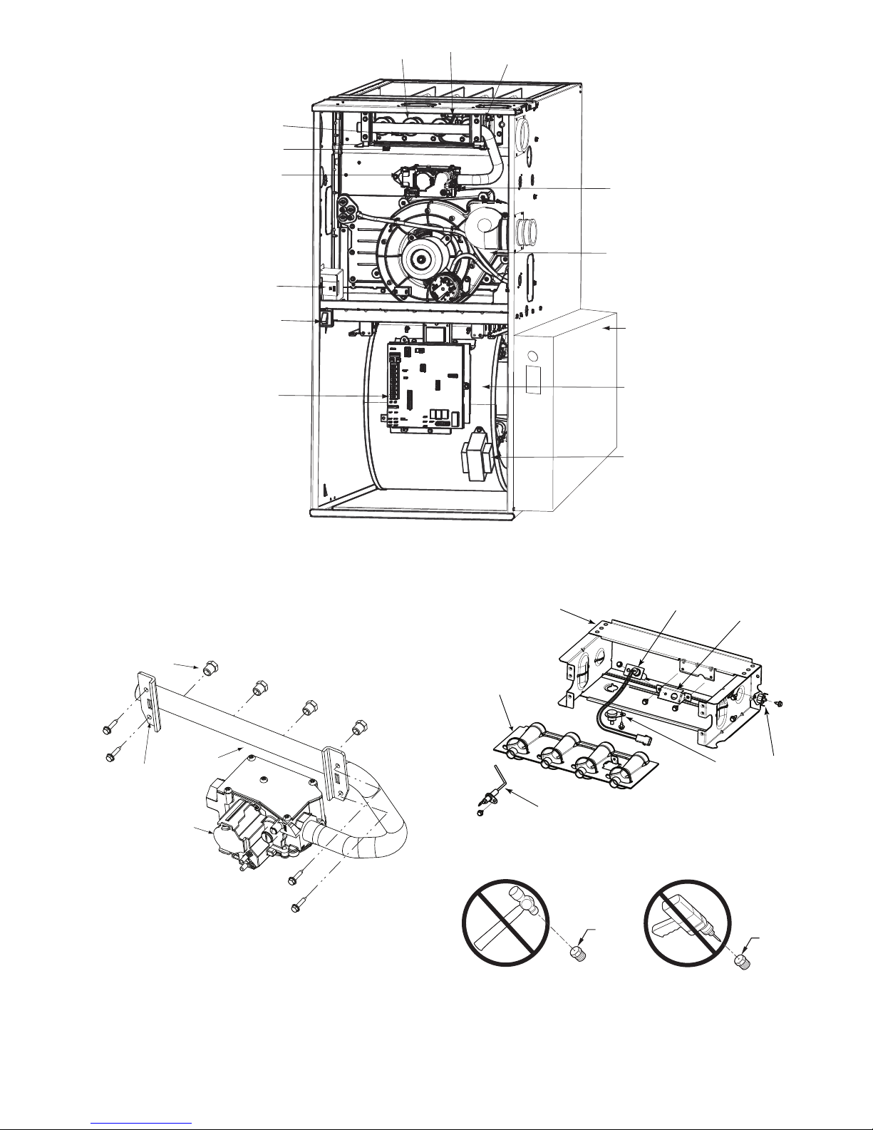
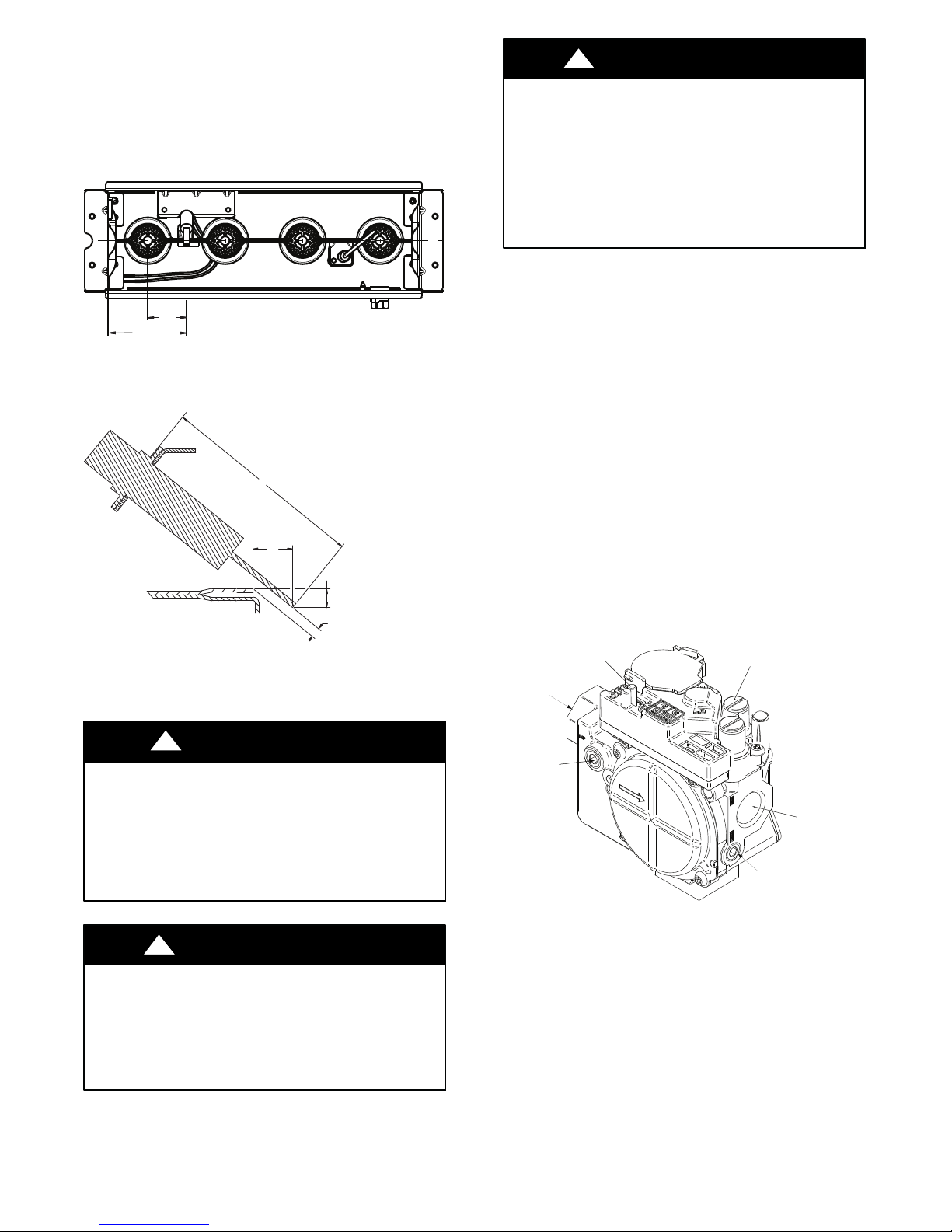
FLAME
SENSOR
MANUAL RESET
ROLLOUT SWITCH
GAS VALVE
OPERATING INSTRUCTIONS
NOT SHOWN (LOCATED ON
MAIN FURNACE DOOR, SEE
OPERATING INSTRUCTIONS
INSIDE DOOR FIGURE).
ELECTRICAL JUNCTION
BOX (IF REQUIRED,
LOCATION MAY VARY)
BLOWER DOOR
SAFETY SWITCH
GAS BURNER
HOT SURFACE
IGNITER
MANUAL RESET
ROLLOUT SWITCH
MAIN LIMIT SWITCH
(BEHIND GAS VALVE)
INDUCER MOTOR
ASSEMBLY
MEDIA CABINET
Orifice
Connect Green/Yellow
ground wire here
FURNACE
CONTROL
BOARD
RATING PLATE NOT SHOWN
(LOCATED ON BLOWER DOOR)
Manifold
Gas Valve
REPRESENTATIVE DRAWING ONLY, SOME MODELS MAY VARY IN APPEARANCE.
Fig. 1 -- Representative Furnace Drawing
BURNER SUPT. ASSY
BURNER ASSY
FLAME SENSOR
(BELOW BURNER)
Fig. 3 -- Burner Assembly
BLOWER AND
MOTOR
CAPACITOR/
POWER CHOKE
IGNITER
A11408
BRACKET, IGNITER
FLAME ROLLOUT
SWITCH
A11403
Fig. 2 -- Manifold Assembly
A11469
BURNER
ORIFICE
BURNER
ORIFICE
A96249
Fig. 4 -- Burner Orifice
3

Table 3 – Orifice Size and Manifold Pressure (In. W.C.) for Gas Input Rate
TWO-STAGE FURNACE
(TABULATED DATA BASED ON 20,000 BTUH HIGH-HEAT / 13,000 BTUH LOW-HEAT PER BURNER,
DERATED 2%/1000 FT (305M) ABOVE SEA LEVEL)
ALTITUDE
RANGE
ft (m)
092543 3.6 / 1.5 43 3.7 / 1.6 43 3.8 / 1.6 42 3.2 / 1.4
(0) 950 43 3.4 / 1.4 43 3.5 / 1.5 43 3.6 / 1.5 43 3.7 / 1.6
to 1000 44 3.5 / 1.5 44 3.6 / 1.5 44 3.8 / 1.6 43 3.4 / 1.4
U.S.A. and CanadaU.S.A. On
y U.S.A. Only U.S.A. and Canada
l
U.S.A. On
ly
ly
U.S.A. On
2000 1050 44 3.2 / 1.3 44 3.3 / 1.4 44 3.4 / 1.4 44 3.5 / 1.5
(610) 1075 45 3.7 / 1.6 45 3.8 / 1.6 44 3.3 / 1.4 44 3.4 / 1.4
U.S.A. 800 42 3.4 / 1.4 42 3.5 / 1.5 42 3.6 / 1.5 42 3.7 / 1.6
2001 (611) 825 43 3.8 / 1.6 42 3.3 / 1.4 42 3.4 / 1.4 42 3.5 / 1.5
to 850 43 3.6 / 1.5 43 3.7 / 1.6 42 3.2 / 1.3 42 3.3 / 1.4
3000 (914) 875 43 3.4 / 1.4 43 3.5 / 1.5 43 3.7 / 1.5 43 3.8 / 1.6
Canada 925 44 3.5 / 1.5 44 3.6 / 1.5 44 3.8 / 1.6 43 3.4 / 1.4
2001 (611) 950 44 3.3 / 1.4 44 3.4 / 1.5 44 3.6 / 1.5 44 3.7 / 1.6
to 975 44 3.2 / 1.3 44 3.3 / 1.4 44 3.4 / 1.4 44 3.5 / 1.5
4500 (1372) 1000 46 3.8 / 1.6 45 3.8 / 1.6 44 3.2 / 1.4 44 3.3 / 1.4
3001 800 43 3.8 / 1.6 42 3.2 / 1.4 42 3.3 / 1.4 42 3.4 / 1.4
(915) 825 43 3.6 / 1.5 43 3.7 / 1.6 43 3.8 / 1.6 42 3.2 / 1.4
to
4000 900 44 3.4 / 1.4 44 3.5 / 1.5 44 3.7 / 1.5 44 3.8 / 1.6
(1219) 925 44 3.2 / 1.4 44 3.4 / 1.4 44 3.5 / 1.5 44 3.6 / 1.5
4001 775 43 3.7 / 1.6 43 3.8 / 1.6 42 3.3 / 1.4 42 3.4 / 1.4
(1220) 800 43 3.5 / 1.5 43 3.6 / 1.5 43 3.7 / 1.6 43 3.8 / 1.6
to
5000 875 44 3.3 / 1.4 44 3.5 / 1.5 44 3.6 / 1.5 44 3.7 / 1.6
(1524) 900 44 3.2 / 1.3 44 3.3 / 1.4 44 3.4 / 1.4 44 3.5 / 1.5
5001 750 43 3.7 / 1.5 43 3.8 / 1.6 42 3.2 / 1.4 42 3.3 / 1.4
(1525) 775 43 3.4 / 1.4 43 3.5 / 1.5 43 3.7 / 1.5 43 3.8 / 1.6
to
6000 850 44 3.3 / 1.4 44 3.4 / 1.4 44 3.5 / 1.5 44 3.6 / 1.5
(1829) 875 45 3.7 / 1.6 44 3.2 / 1.3 44 3.3 / 1.4 44 3.4 / 1.4
6001 700 42 3.2 / 1.3 42 3.3 / 1.4 42 3.4 / 1.4 42 3.5 / 1.5
(1830) 725 43 3.6 / 1.5 43 3.7 / 1.6 43 3.8 / 1.6 42 3.3 / 1.4
to
7000 800 44 3.4 / 1.4 44 3.5 / 1.5 44 3.6 / 1.5 44 3.7 / 1.6
(2133) 825 44 3.2 / 1.3 44 3.3 / 1.4 44 3.4 / 1.4 44 3.5 / 1.5
HEATVALUE0.580.600.620.64
AT ALTIT UDE Orifice Mnfld Press Orifice Mnfld Press Orifice Mnfld Press Orifice Mnfld Press
(Btu/cu ft) No. High/Low No. High/Low No. High/Low No. High/Low
900 43 3.8 / 1.6 42 3.2 / 1.4 42 3.3 / 1.4 42 3.4 / 1.4
975 44 3.7 / 1.6 44 3.8 / 1.6 43 3.4 / 1.5 43 3.6 / 1.5
1025 44 3.3 / 1.4 44 3.5 / 1.5 44 3.6 / 1.5 44 3.7 / 1.6
1100 46 3.7 / 1.6 46 3.8 / 1.6 45 3.8 / 1.6 44 3.2 / 1.4
900 44 3.7 / 1.6 44 3.8 / 1.6 43 3.5 / 1.5 43 3.6 / 1.5
775 42 3.3 / 1.4 42 3.4 / 1.4 42 3.5 / 1.5 42 3.6 / 1.5
850 44 3.8 / 1.6 43 3.5 / 1.5 43 3.6 / 1.5 43 3.7 / 1.6
875 44 3.6 / 1.5 44 3.7 / 1.6 43 3.4 / 1.4 43 3.5 / 1.5
950 45 3.7 / 1.6 44 3.2 / 1.3 44 3.3 / 1.4 44 3.4 / 1.4
750 42 3.3 / 1.4 42 3.4 / 1.4 42 3.5 / 1.5 42 3.6 / 1.5
825 44 3.8 / 1.6 43 3.4 / 1.4 43 3.5 / 1.5 43 3.6 / 1.5
850 44 3.5 / 1.5 44 3.7 / 1.5 44 3.8 / 1.6 43 3.4 / 1.4
925 46 3.8 / 1.6 45 3.7 / 1.6 44 3.2 / 1.4 44 3.3 / 1.4
725 42 3.2 / 1.4 42 3.3 / 1.4 42 3.4 / 1.5 42 3.5 / 1.5
800 44 3.7 / 1.6 44 3.8 / 1.6 43 3.4 / 1.5 43 3.5 / 1.5
825 44 3.5 / 1.5 44 3.6 / 1.5 44 3.7 / 1.6 44 3.8 / 1.6
900 46 3.7 / 1.6 46 3.8 / 1.6 45 3.8 / 1.6 44 3.2 / 1.4
675 42 3.4 / 1.4 42 3.5 / 1.5 42 3.6 / 1.5 42 3.8 / 1.6
750 43 3.4 / 1.4 43 3.5 / 1.5 43 3.6 / 1.5 43 3.7 / 1.6
775 44 3.6 / 1.5 44 3.7 / 1.6 43 3.4 / 1.4 43 3.5 / 1.5
850 46 3.8 / 1.6 45 3.8 / 1.6 44 3.2 / 1.4 44 3.3 / 1.4
SAGLARUTANFOYTIVARGCIFICEPSSAG.GVA
A11252A
4
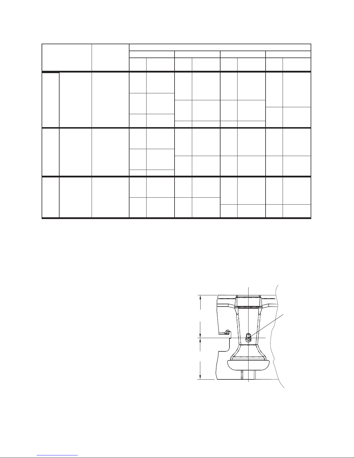
Table -- 3 Orifice Size and Manifold Pressure (In. W.C.) for Gas Input Rate (continued)
TWO-STAGE FURNACE
(TABULATED DATA BASED ON 20,000 BTUH HIGH-HEAT / 13,000 BTUH LOW-HEAT PER BURNER,
DERATED 2%/1000 FT (305M) ABOVE SEA LEVEL)
ALTITUDE
RANGE
ft (m)
7001 675 43 3.8 / 1.6 42 3.2 / 1.4 42 3.3 / 1.4 42 3.4 / 1.5
(2134) 700 43 3.5 / 1.5 43 3.7 / 1.5 43 3.8 / 1.6 42 3.2 / 1.4
to
8000 775 44 3.3 / 1.4 44 3.4 / 1.4 44 3.5 / 1.5 44 3.7 / 1.5
(2438) 800 45 3.8 / 1.6 44 3.2 / 1.4 44 3.3 / 1.4 44 3.4 / 1.4
8001 650 43 3.8 / 1.6 42 3.2 / 1.4 42 3.3 / 1.4 42 3.4 / 1.4
(2439) 675 43 3.5 / 1.5 43 3.6 / 1.5 43 3.7 / 1.6 42 3.2 / 1.3
to
U.S.A. OnlyU.S.A. Only U.S.A. Only
* Orifice numbers shown in BOLD are factory-installed.
9000 750 44 3.3 / 1.4 44 3.4 / 1.4 44 3.5 / 1.5 44 3.6 / 1.5
(2743) 775 45 3.7 / 1.6 44 3.2 / 1.3 44 3.3 / 1.4 44 3.4 / 1.4
9001 600 42 3.3 / 1.4 42 3.4 / 1.5 42 3.6 / 1.5 42 3.7 / 1.6
(2744) 625 43 3.7 / 1.6 42 3.2 / 1.3 42 3.3 / 1.4 42 3.4 / 1.4
to
10000 700 44 3.4 / 1.4 44 3.5 / 1.5 44 3.7 / 1.5 44 3.8 / 1.6
(3048) 725 44 3.2 / 1.3 44 3.3 / 1.4 44 3.4 / 1.4 44 3.5 / 1.5
HEATVALUE0.580.600.620.64
AT ALTIT UDE Orifice Mnfld Press Orifice Mnfld Press Orif ice Mnfld Press Orifice Mnfld Press
(Btu/cu ft) No. High/Low No. High/Low No. High/Low No. High/Low
650 42 3.4 / 1.4 42 3.5 / 1.5 42 3.6 / 1.5 42 3.7 / 1.6
725 44 3.8 / 1.6 43 3.4 / 1.4 43 3.5 / 1.5 43 3.6 / 1.5
750 44 3.5 / 1.5 44 3.7 / 1.5 44 3.8 / 1.6 43 3.4 / 1.4
825 46 3.7 / 1.6 46 3.8 / 1.6 45 3.8 / 1.6 44 3.2 / 1.4
625 42 3.4 / 1.4 42 3.5 / 1.5 42 3.6 / 1.5 42 3.7 / 1.6
700 44 3.7 / 1.6 43 3.4 / 1.4 43 3.5 / 1.5 43 3.6 / 1.5
725 44 3.5 / 1.5 44 3.6 / 1.5 44 3.7 / 1.6 44 3.8 / 1.6
650 43 3.5 / 1.5 43 3.6 / 1.5 43 3.7 / 1.6 43 3.8 / 1.6
675 44 3.7 / 1.6 44 3.8 / 1.6 43 3.4 / 1.4 43 3.5 / 1.5
Determine natural gas orifice size and manifold pressures for
correct input at installed altitude by using Table 3.
1. Obtain yearly heat--value average (at installed altitude) for
local gas supply.
2. Obtain yearly specific--gravity average for local gas supply.
3. Find installation altitude in Table 3.
NOTE: For Canada altitudes of 2000 to 4500 ft. (610 to 1372
M), use U.S.A. Altitudes of 2001 to 3000 ft. (610 to 914 M) in
Tab le 3 .
4. Find closest natural gas heat value and specific gravity in
Tab le 3 .
5. Follow heat--value line and specific--gravity line to point
of intersection to find orifice size and high and low manifold pressure settings.
Furnacegas input rate on furnace rating plate is for installations at
altitudes up to 2000 ft.
In the U.S.A.; the input rating for altitudes above 2000 ft. (610
M) must be reduced by 2 percent for each 1000 ft. (305 M) above
sea level.
In Canada; the input rating must be derated by 5 percent for
altitudes of 2000 ft. to 4500 ft. (610 to 1372 M) above sea level.
The Conversion Kit Rating Plate accounts for high altitude
derate.
INSTALL ORIFICES
Install main burner orifices. DO NOT use Teflon tape.
Finger--tighten orifices at least one full turn to prevent
cross--threading, then tighten with wrench. There are enough
orifices in each kit for largest furnace. Discard extra orifices.
NOTE: DO NOT reinstall the manifold at this time.
SAGLARUTANFOYTIVARGCIFICEPSSAG.GVA
A11252B
REMOVE MIXER SCREWS FROM THE BURNERS
NOTE: Each burner contains a mixer screw that must be
removed. Refer to Fig. 5 for the mixer screw location.
1. Remove the mixer screws from the burners.
NOTE: It is not necessary to plug the hole in the burner when
the mixer screws are removed.
Location of mixer screw
1.9”
(48.76 mm)
1.8”
(46.96 mm)
Fig. 5 -- Mixer Screw Location
that must be removed
A11501
5
REINSTALL BURNER ASSEMBLY
To reinstall burner assembly:
1. Attach flame sensor to burner assembly.
2. Insert one--piece burner in slot on sides of burner box and
slide burner back in place.
3. Reattach HSI wires to HSI.
4. Verify igniter to burner alignment. See Fig. 6 and 7.
1-1/4-in.
(31.8)
2-1/2-in.
(64.4)
Fig. 6 -- Igniter Position -- Back View
2 − in.
(50 mm)
3/8 − in.
(9.6 mm)
3/16− in.
(4.6 mm)
3/32− in., +1/32 -3/64-in.
(2.5 mm
, +0.8 -1.5)
Fig. 7 -- Igniter Position -- Side View
CONVERT GAS VALVE
A11405
A12392
!
WARNING
ELECTRICAL SHOCK, FIRE OR EXPLOSION
HAZARD
Failure to follow this warning could result in personal
injury, death or property damage.
Before installing, modifying, or servicing system, main
electrical disconnect switch must be in the OFF position and
install a lockout tag. There may be more than one
disconnect switch. Lock out and tag switch with a suitable
warning label. Verify proper operation after servicing.
1. Refer to Fig. 8.
2. Be sure gas and electrical supplies to furnace are off.
3. Remove caps that conceal the adjustment screws for high
heat and low heat gas--valve regulators. (See Fig. 8.)
4. Remove the high heat and low heat regulator adjustment
screws.
5. Remove the high heat and low heat Propane regulator
springs (white).
6. Install the high heat and low heat natural gas regulator
springs (silver).
7. Install the high heat and low heat regulator adjustment
screws.
8. Turn high heat stage adjusting screw clockwise (in) 12 full
turns. This will increase the manifold pressure closer to the
natural set point.
9. Turn low heat stage adjusting screw clockwise (in) 9.5 full
turns. This will increase the manifold pressure closer to the
natural gas low heat set point.
10. DO NOT install regulator seal caps at this time.
TWO-STAGE
ON/OFF Switch
1/2” NPT Inlet
Regulator Seal Cap
Regulator Adjustment
Regulator Seal Cap
under Cap
!
CAUTION
UNIT DAMAGE HAZARD
Failure to follow this caution may result in unit damage
The G or J gas valve must be converted and pre--adjusted
before operating on natural gas. The E valves must be
pre--adjusted before operating on natural gas. If left this
way, sooting and corrosion will occur leading to early heat
exchanger failure.
!
WARNING
FIRE, EXPLOSION, ELECTRICAL SHOCK
HAZARD
Failure to follow this warning could result in personal
injury, death or property damage.
Gas supply MUST be shut off before disconnecting
electrical power and proceeding with conversion.
1/8” NPT Inlet
Pressure Tap
1/2” NPT Outlet
1/8” NPT Manifold
Pressure Tap
A11152
Fig. 8 -- Two--stage valve
REMOVE LOW GAS PRESSURE SWITCH
NOTE: There are two ways that the Low Gas Pressure Switch
(LGPS) could have been installed during the original natural to
Propane gas conversion.
All 14 3/16-in.(360 mm) Casings or Vent Passed Between
Inducer Assembly and BurnerAssembly
If the vent pipe passes between the inducer and burner assembly,
or the furnace is a 14 3/16-in. (360 mm) wide casing, the switch
may have been installed as follows (See Fig 9).
1. Remove low--gas pressure switch, brass street 90_ elbow,
brass Hex nipple, brass Tee and black iron street 90_ elbow from the gas valve inlet pressure tap. (See Fig 9.)
6
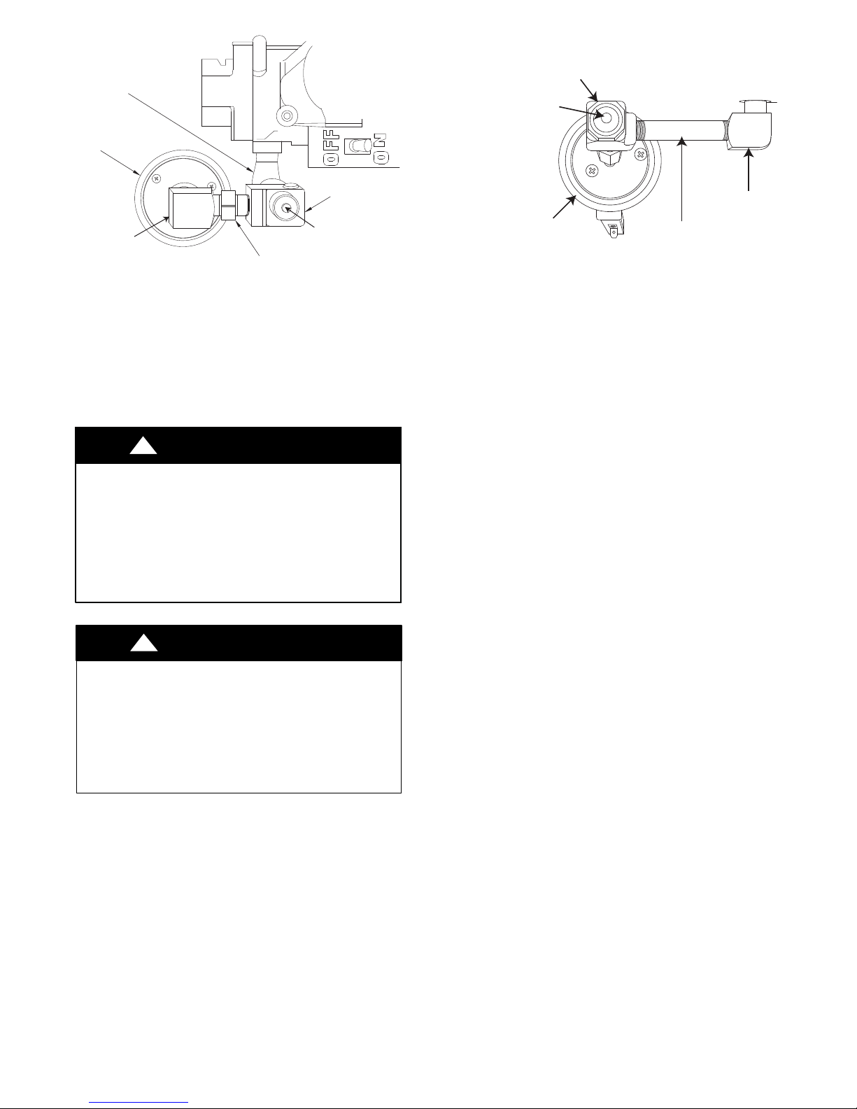
Black Iron Street 90 Pointing
Low Gas Pressure Switch
Brass Street Tee
Inlet Pressure Tap
with Plug
Brass Street Tee
Inlet Pressure Tap with
Brass Street 90
Brass Hex Nipple
A11367
Fig. 9 -- Low Gas Pressure Switch -- All Widths
NOTE: Use pipe dope approved for use with Propane gas. DO
NOT use Teflon tape.
2. Apply pipe dope sparingly to the 1/8--in. NPT pipe plug
(provided in kit) and install in the 1/8--in. tapped inlet-pressure tap opening in the gas valve. DO NOT over-tighten. Check for gas leaks after gas supply has been
turned on.
!
WARNING
FIRE AND EXPLOSION HAZARD
Failure to follow this warning could result in personal injury
and/or death.
NEVER test for gas leaks with an open flame. Use a
commercially available soap solution made specifically for
the detection of leaks to check all connections. A fire or
explosion may result causing property damage, personal
injury or loss of life.
!
AVERTISSEMENT
RISQUE D’EXPLOSION ET D’INCENDIE
Le fait de ne pas suivre cet avertissement pourrait entraîner des
dommages corporels et / ou la mort.
Ne jamais examiner pour les fuites de gaz avec une flamme
vive. Utilisez plutôt un savon fait specifiquement pour la
détection des fuites de gaz pour verifier tous les connections.
Un incendie ou une explosion peut entrainer des dommages
matériels, des blessures ou la mort.
Casings Wider Than 14 3/16-in. (360 mm) /Vent Does Not
Pass Between Inducer and Burner Assembly
If the vent pipe does not pass between the inducer and burner
assembly, or the furnace is wider than a 14 3/16-in. (360 mm)
wide casing, install the switch as follows (See Fig 10):
1. Remove Low Gas Pressure Switch, brass street tee, brass
nipple and brass street 90_ elbow from the gas valve inlet
pressure tap. (See Fig 10.)
NOTE: Use pipe dope approved for use with Propane gas. DO
NOT use Teflon tape.
Brass Street
Low Gas Pressure Switch
Brass Nipple
A11517
Fig. 10 -- Alternate Low Gas Pressure Switch --
17 1/2--in. (445 mm) and wider furnaces
2. Apply pipe dope sparingly to the 1/8--in. NPT pipe plug
(provided in kit) and install in the 1/8--in. tapped inlet-pressure tap opening in the gas valve. DO NOT over-tighten. Check for gas leaks after gas supply has been
turned on.
INSTALL MANIFOLD
1. Align the orifices in the manifold assembly with the support rings on the end of the burner.
2. Insert the orifices in the support rings of the burners. Manifold mounting tabs should fit flush against the burner box
NOTE: If manifold does not fit flush against the burner box, the
burners are not fully seated forward. Remove the manifold and
check burner positioning in the burner box assembly.
3. Attach the green/yellow wire and ground terminal to one
of the manifold mounting screws.
4. Install the remaining manifold mounting screws.
5. Connect the wires to the flame sensor and hot surface igniter.
6. Connect the connector harness to gas valve.
7. Rewire unit low pressure switch (LPS) as follows:
a. Trace one of the orange wires previously disconnected
from the LGPS back to the NO terminals of the LPS.
b. Trace the other orange wire previously disconnected
from the LGPS back to itssplice connection with theyellow wire ofthe furnace wireharness. Disconnect and discard this orange wire and the splice connector.
c. Connect the yellow wire of the furnace wire harness (see
“b” above) to the NO terminal of the LPS.
d. Referto thefurnace wiring diagram toensureproperloca-
tion of wires.
NOTE: Use only propane-resistant pipe dope. DO NOT use
Teflon tape.
8. Insert the gas pipe through the grommet in the casing. Apply a thin layer of pipe dope to the threads of the pipe and
thread the pipe by into the gas valve.
NOTE: Use a back-up wrench on the gas valve to prevent the
valve from rotating on the manifold or damaging the mounting to
the burner box.
9. With a back-up wrench on the inlet boss of the gas valve,
finish tightening the gas pipe to the gas valve.
10. Turn gas on at electric switch on gas valve.
7
 Loading...