

HVAC Partners KGANP26012SP Installation Instructions Manual
Installation Instructions
Gas Conversion Kit Natural-
KGANP26012SP
to-Propane for Variable-Speed
and 2–Speed Furnaces
CERTIFIED
NOTE: Read the entire instruction manual before starting the installation.
This symbol → indicates a change since the last issue.
SAFETY CONSIDERATIONS
Installing and servicing heating equipment can be hazardous due to gas and electrical components. Only trained and qualified personnel should
install, repair, or service heating equipment.
Untrained personnel can perform basic maintenance functions such as cleaning and replacing air filters. All other operations must be performed
by trained service personnel. When working on heating equipment, observe precautions in the literature, on tags, and on labels attached to or
shipped with the unit, and other safety precautions that may apply.
Follow all safety codes. In the United States, follow all safety codes including the National Fuel Gas Code (NFGC) NFPA No. 54-1999/ANSI
Z223.1-1999. In Canada, refer to the NationalStandard of Canada, Natural Gas and Propane Installation Codes (NSCNGPIC), CAN/CGA-B149.1
and .2-M95.
Wear safety glasses and work gloves. Have a fire extinguisher available during start-up, adjustment procedures, and service calls.
Recognize safety information. This is the safety-alert symbol
alert to the potential for personal injury.
Understand the signal words DANGER, WARNING, CAUTION, and NOTE. The words DANGER, WARNING, and CAUTION are used with
the safety-alert symbol. DANGER identifies the most serious hazards which will result in severe personal injury or death. WARNING signifies
hazards which could result in personal injury or death. CAUTION is used to identify unsafe practices which would result in minor personal injury,
or product and property damage. NOTE is used to highlight suggestions which will result in enhanced installation, reliability, or operation.
. When you see this symbol on the furnace and in instructions or manuals, be
WARNING: This conversion kit shall be installed by a qualified service agency in accordance with the manufacturer’s
instructions and all applicable codes and requirements of the authority having jurisdiction. If the information in these
instructions is not followed exactly, a fire, explosion, or production of carbon monoxide may result causing property
damage, personal injury, or loss of life. The qualified service agency is responsible for the proper installation of this furnace
with this kit. The installation is not proper and complete until the operation of the converted appliance is checked as
specified in the manufacturer’s instructions supplied with the kit.
AVERTISSEMENT: Cette trousse de conversion ne doit être installée que par le représentant d’un organisme qualifié
et conformément aux instructions du fabricant et à tous les codes et exigences pertinents de l’autorité compétente. Les
instructions du présent guide doivent être suivies afin de réduire au minimum au risque d’incendie ou d’explosion de
dommange matériels, de blessure ou de mort. L’organisme qualifié responsable de l’installation adéquate de cette trousse.
L’installation n’est pas adéquate ni complète tant que le bon fonctionnement de l’appereil converti n’a pas été vérfié selon
les instructions du fabricant fornies avec la trousse.
This instruction covers the installation of gas conversion kit Part No. KGANP26012SP to convert the following furnaces from natural gas usage
to propane gas usage. See appropriate section for your furnace type.
• Section 1—Models 58DXT, 58TMA, 58TUA, 58UHV, 58UXT, 58UXV, 330AAV, 330JAV, 331AAV, 331JAV, 333BAV, and 333JAV
Induced-Combustion, Hot-Surface Ignition, 2-Speed and Variable-Speed, Non-Condensing Furnaces. This kit is designed for use in furnaces
with 40,000 through 140,000 Btuh gas input rates.
Form: AG-GANP-23 Cancels: AG-GANP-22 Printed in U.S.A. 7–00 Catalog No. 63GA-NP5
INTRODUCTION
• Section 2—Models 58MVP and 355MAV Direct-Vent, Multipoise, Hot-Surface Ignition, Variable-Speed, Condensing Furnaces. This kit is
designed for use in furnaces with 40,000 through 120,000 Btuh gas input rates.
IMPORTANT: This kit can replace conversion kit KGANP250112SP, as specified on unit rating plate, when gas valve is replaced with
Two-Stage Gas Valve P/N EF33CW198 (White-Rodgers 36E55). Replacement gas valve available through RCD.
WARNING: Improper installation, adjustment, alteration, service, maintenance, or use can cause carbon monoxide
poisoning, explosion, fire, electrical shock, or other conditions which could result in personal injury or death. Consult a
qualified installer, service agency, local gas supplier, or your distributor or branch for information or assistance. The
qualified installer or agency must use only factory-authorized kits or accessories when modifying this product. Failure to
follow instructions could result in serious injury or property damage.
CAUTION: Gas supply MUST be shut off before disconnecting electrical power and proceeding with conversion.
DESCRIPTION AND USAGE
This kit is designed for use in the furnaces listed above. See Table 1 for kit contents. More parts are shipped in kit than will be needed to complete
conversion. When installation is complete, discard extra parts.
→
DESCRIPTION PART NO. QUANTITY
Main Burner Orifice (Drill Size 1.25mm) LH32DB209 7
Main Burner Orifice (Drill Size No. 55) LH32DB201 7
Main Burner Orifice (Drill Size No. 56) LH32DB206 7
Diverter Plate 323184-301 1
Low Gas Pressure Switch (Propane) (LGPS) HK02LB018 1
Pipe Nipple (1/8 in. X 1-1/2 in.)d CA01CA006 1
90° Street Elbow (1/8 in.) CA15RA001 1
Splice Connector (1/4 in. Male, Both Ends) 6617D55 1
Splice Connector (3/16 in. Male, Both Ends) HY89SC047 1
Orange Wire Assembly (18 in.) W183X23-04-018 2
Yellow Wire Assembly (6 in.) W183Y66-11-014 1
Yellow Wire Assembly (14 in.) W183Y66-11-014 1
Wire Tie HY76TB125 1
Conversion Rating Plate Label-NonCondensing Furnaces 326108-201 1
Conversion Rating Plate Label-Condensing Furnaces 326108-203 1
Conversion Responsibility Label 326108-204 1
Gas Control Conversion Label 326108-202 1
Installation Instructions AG-GANP-23 1
Table 1 — Kit Contents
INSTALLATION
SECTION 1—MODELS 58DXT, 58TMA, 58TUA, 58UHV, 58UXT, 58UXV, 330AAV, 330JAV, 331AAV, 331JAV, 333BAV, AND 333JAV
INDUCED-COMBUSTION, HOT-SURFACE IGNITION, 2-SPEED AND VARIABLE-SPEED, NON-CONDENSING FURNACES
PROCEDURE 1—INSTALL MAIN BURNER ORIFICES
NOTE: See Fig. 1 or 2 for component location.
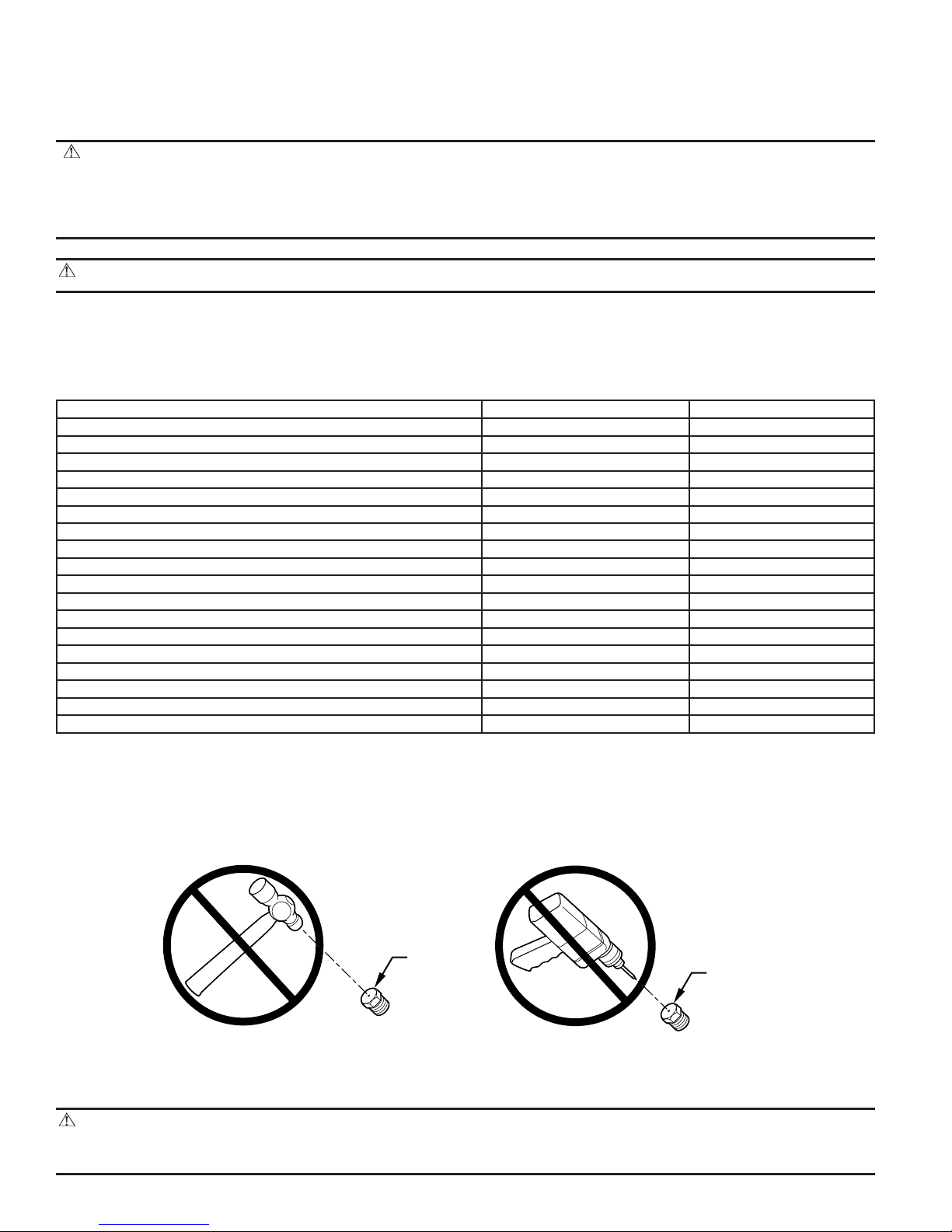
CAUTION: DO NOT redrill burner orifices. Improper drilling (burrs, out-of-round holes, etc.) can cause excessive
burner noise and misdirection of burner flames. This can result in flame impingement of the burners and heat exchangers,
causing failure. Obtain new orifices if orifice size must be changed.
BURNER
ORIFICE
—2—
BURNER
ORIFICE
A96249
1. Turn off furnace gas and electrical supplies.
2. Remove control access door.
3. Turn furnace gas valve switch to OFF position.
4. Remove burner hold-down bracket.
5. Remove burners from manifold.
6. Remove and discard orifices from manifold.
7. Refer to conversion kit rating plate 326108–201 to determine main burner orifice size.
→
Furnace gas input rate on rating plate is for installations at altitudes up to 2000 ft.
In the U.S.A., the input rating for altitudes above 2000 ft must be reduced by 4 percent for each 1000 ft above sea level.
In Canada, the input rating must be derated by 10 percent for altitudes of 2000 ft to 4500 ft above sea level.
8. Install main burner orifices. Do not use Teflon tape. Finger-tighten orifices at least 1 full turn to prevent cross-threading, then tighten with
wrench. There are enough orifices in each kit for largest furnace. Discard extra orifices. Orifices of other sizes must be field supplied and
are available through your local distributor.
9. Reinstall main burners on manifold. Burners should be installed left (flame sensor side) to right (ignitor side) to ensure proper alignment
of the burner crossover slot. (See Fig. 4 for ignitor position.)
10. Reinstall burner hold-down bracket.
11. For models 58DXT, 58UXT, 58UXV, 330JAV, 331JAV, and 333JAV only, remove NO
NOTE: Models 58DXT, 58UXT, 58UXV, 330JAV, 331JAV and 333JAV are supplied with NO
with Natural Gas in NO
emissions-regulated areas.
X
emissions-reducing device as follows:
X
emissions-reduction devices necessary for use
X
CAUTION: Furnace models 58DXT, 58UXT, 58UXV, 330JAV, 331JAV, and 333JAV, must have low NOXcoils removed
prior to operating furnace on propane gas.
CAUTION: Label all wires prior to disconnection when servicing controls. Wiring errors can cause improper and
dangerous operation.
ATTENTION: Lors des opérations d’entretien des commandes, étiqueter tous les fils avant de les déconnecter. Toute
erreur de câblage peut être une source de danger et de panne.
a. Be sure gas and electrical supplies to furnace are off.
b. Remove wires from gas valve. Note location for reassembly.
c. Remove wires from flame sensor and flame rollout safety switch(es). Disconnect ignitor wire connector.
d. Remove 4 screws that hold gas control assembly to heat exchanger cell panel and remove gas control assembly.
e. Using needle nose pliers, remove coil from bracket on each heat exchanger cell inlet plate. (See Fig. 5.)
f. Replace gas control assembly and secure to heat exchanger cell panel using 4 previously removed screws.
g. Reconnect wires to flame sensor and flame rollout safety switch(es), and reconnect ignitor wire connector. See furnace wiring label to
ensure proper location of wires.
h. Reconnect wires to gas valve. See wiring label on furnace to ensure proper location of wires.
i. Reconnect gas supply pipe to gas valve using backup wrench on gas valve to prevent rotation and improper orientation.
NOTE: Use propane-gas resistant pipe dope to prevent gas leaks. DO NOT use Teflon tape.
PROCEDURE 2—PRE-ADJUST GAS VALVE
CAUTION: The gas valve must be pre-adjusted before operating on propane gas. Failure to follow this caution could
result in excess underfire and flashback. If left this way sooting and corrosion will occur leading to early heat exchanger
failure.
1. Be sure gas and electrical supplies to furnace are off.
2. Remove caps that conceal adjustment screws for high- and low-heat stage gas-valve regulators. (See Fig. 3.)
3. Turn low-heat stage adjusting screw (5/64-in. hex allen wrench) clockwise (in) 1 full turn. This will increase the manifold pressure closer
to the propane low-heat set point.
4. Turnhigh-heat stage adjusting screw (5/64-in. hex allen wrench) clockwise (in) 2 full turns. This will increase the manifold pressure closer
to the propane high-heat set point.
5. Replace caps that conceal gas-valve regulator adjustment screws.
PROCEDURE 3—CHECK INLET GAS PRESSURE
NOTE: This kit is to be used only when inlet gas pressure is between 11.0-in. wc and 13.6-in. wc.
1. Be sure main gas and electric supplies to furnace are off.
2. Remove 1/8-in. pipe plug from inlet pressure tap on gas valve. (See Fig. 3.)
—3—
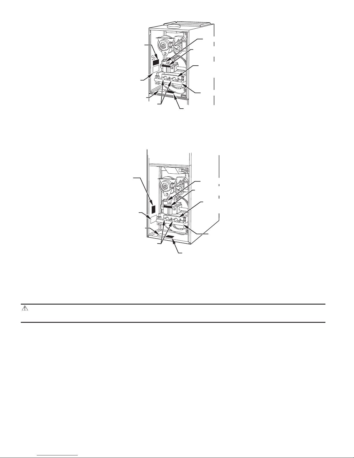
CONVERSION
RATING
PLATE
FURNACE
RATING
PLATE
CLEARANCE LABEL
BURNERS
CONVERSION
RESPONSIBILITY
LABEL
GAS VALVE
GAS CONTROL
CONVERSION LABEL
BURNER
HOLD–DOWN
BRACKET
MANIFOLD
A99219
Fig. 1—Upflow and Upflow/Horizontal, 2-Speed and Variable-Speed, Non-Condensing Furnace Components and Conversion
Label Location
CONVERSION
RA TING
PLA TE
FURNACE
RA TING
PLA TE
CLEARANCE LABEL
BURNERS
CONVERSION
RESPONSIBILITY
LABEL
GAS VALVE
GAS CONTROL
CONVERSION LABEL
BURNER
HOLD–DOWN
BRACKET
MANIFOLD
A99220
Fig. 2—Downflow and Downflow/Horizontal, 2-Speed, Non-Condensing Furnace Components and Conversion Label
Location
3. Attach manometer to inlet pressure tap on gas valve. (See Fig. 17.)
CAUTION: DO NOT operate furnace more than 1 minute to check inlet gas pressure as conversion is not complete at
this time.
4. Turn on furnace power supply.
5. Turn gas supply manual shutoff valve to ON position.
6. Turn furnace gas valve switch to ON position.
7. Jumper R-W/W1 and R-W2 thermostat connections on control. (See Fig. 6.) This runs the furnace in high heat.
8. When main burners ignite, confirm inlet gas pressure is between 11.0-in. wc and 13.6-in. wc.
9. Remove jumper across R-W/W1 and R-W2 thermostat connections to terminate call for heat.
10. Turn furnace gas valve switch to OFF position.
11. Turn gas supply manual shutoff valve to OFF position.
12. Turn off furnace power supply.
13. Remove manometer, but do not reinstall gas-valve inlet pressure-tap plug. (See Fig. 3.)
PROCEDURE 4—INSTALL LOW GAS PRESSURE SWITCH (LGPS)
NOTE: The inlet gas pipe must be disconnected from valve so pressure switch can be installed.
NOTE: Use propane-gas-resistant pipe dope on all connections to prevent gas leaks. DO NOT use Teflon tape.
—4—
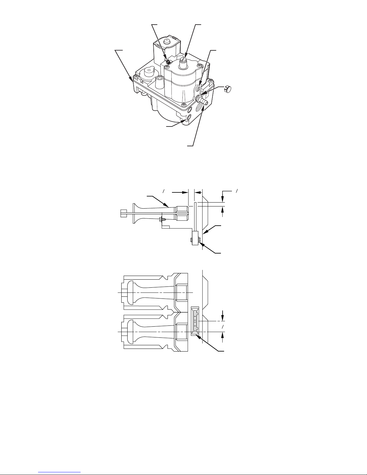
ON/OFF
SWITCH
LOW-FIRE
ADJUSTMENT
ALLEN SCREW
(UNDER CAP)
INLET
PRESSURE
TAP
O
F
F
ON
MANIFOLD
PRESSURE
TAP
BURNER ENCLOSURE
REFERENCE PRESSURE TAP
(VARIABLE-SPEED, CONDENSING
FURNACES ONLY)
Fig. 3—Redundant Automatic 2-Stage Gas Valve
13
32
BURNER
"
HIGH-FIRE
ADJUSTMENT
ALLEN SCREW
(UNDER CAP)
PLUG BUTTON
(2-STAGE AND
VARIABLE–SPEED,
NON–CONDENSING
FURNACES ONLY)
11
32
"
A99218
CELL
PANEL
HOT
SURFACE
IGNITOR
ASSEMBLY
C
IGNITOR
L
7
8
"
C
BURNER
L
IGNITOR
ASSEMBLY
A93347
Fig. 4—Position of Ignitor to Burner
1. Apply pipe dope sparingly to both ends of pipe nipple (provided in kit) and install nipple in 1/8-in. tapped opening in gas valve. Finger
tighten. (See Fig. 8.)
2. Apply pipe dope sparingly to threaded end of street elbow (provided in kit) and install elbow on nipple. Finger tighten. Use a small pipe
wrench for final tightening.
3. Point male end of street elbow vertically up. (See Fig. 8.)
4. Install propane low gas pressure switch (provided in kit) on street elbow. After switch has been finger tightened, use small wrench on base
of pressure switch for final tightening. When pressure switch is tight, switch terminals should point as shown in Fig. 8 relative to gas valve
and clear control compartment access door.
5. Apply pipe dope sparingly to end of inlet gas pipe and reconnect pipe to gas valve.
—5—
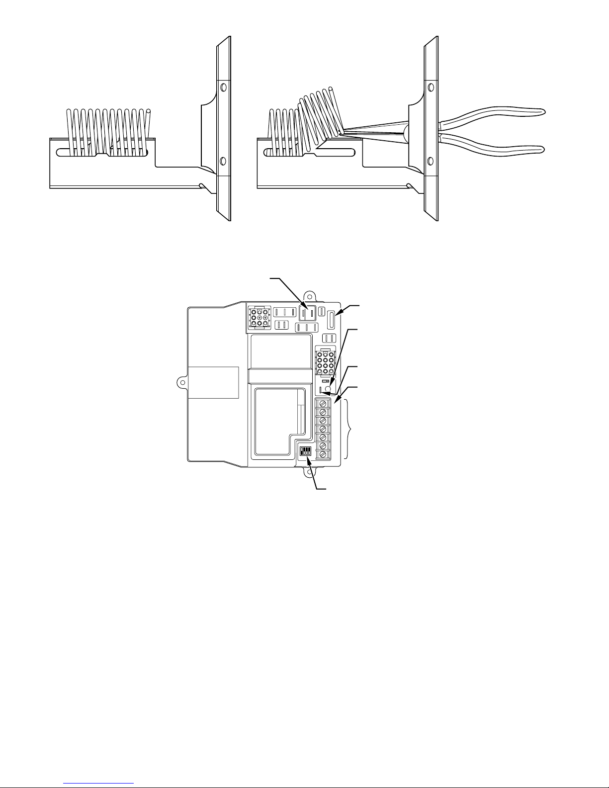
AS SHIPPED COIL REMOVAL
Fig. 5—Removal of Low NO
X
Coil
EAC - ELECTRONIC
AIR CLEANER
(115-VAC 1 AMP MAX)
78 9
456
123
L2
PR2
L1
PR1
PARK
COM
EAC-2
EAC-1
FU1
-HEAT
-HEAT
HI-GAS
LO-GAS
HI-COOL
SEC-1
10 11 12
789
456
123
MASTER SLAVE
1
TWIN
TEST
1
3
LED
SEC-2
HUM
GRY/Y2W/W1
3-AMP
FUSE
LED DIAGNOSTIC
LIGHT
TWIN / TEST
TERMINAL
HUM HUMIDIFIER
(24-VAC 0.5
AMP MAX)
24-VOLT
1234
OFF
ON
THERMOSTAT
TERMINALS
24 V
COM
W2
FURNACE AND
BLOWER OFF DELAY
SETUP SWITCHES
A95171
Fig. 6—Non-Condensing Furnace Control Center (2-Speed Control Shown)
PROCEDURE 5—MODIFY PRESSURE SWITCH WIRING
1. Disconnect yellow wire from low-heat pressure switch LPS on inducer housing. Add 3/16-in. splice connector to this wire.
2. Connect uninsulated terminal of 6-in. yellow wire (provided in kit) to splice connector. Connect other end to C terminal on low gas pressure
switch LGPS on gas valve.
3. Connect insulated terminal of 14-in. yellow wire (provided in kit) to NO terminal on low gas pressure switch LGPS. Connect other end to
pressure switch LPS located on inducer housing.
4. Route yellow wires along wire harness. Secure with wire tie provided in kit.
PROCEDURE 6—CHECK FURNACE OPERATION AND MAKE NECESSARY ADJUSTMENTS
1. Be sure main gas and electric supplies to furnace are off.
2. Remove 1/8-in. pipe plug from manifold pressure tap on downstream side of gas valve. (See Fig. 3.)
3. Attach manometer to manifold pressure tap on gas valve. (See Fig. 17)
4. Turn gas supply manual shutoff valve to ON position.
5. Turn furnace gas valve switch to ON position.
A93348
—6—
 Loading...