

HVAC Partners EHC09AKCN, EHC15AKF, EHC15AKB, EHC20AKF, EHC20AKB Installation Instructions Manual
...
INSTALLATION INSTRUCTIONS
ELECTRIC HEAT ACCESSORY
EHC09AKCN, EHC15AKF, EHC15AKB, EHC20AKF, EHC20AKB,
EHC25AHCF, EHC30AHCF
Safety Labeling and Signal Words
DANGER, WARNING, CAUTION, and NOTE
The signal words DANGER, WARNING, CAUTION, and NOTE
are used to identify levels of hazard seriousness. The signal
word DANGER is only used on product labels to signify an immediate hazard. The signal words WARNING, CAUTION, and
NOTE will be used on product labels and throughout this manual
and other manuals that may apply to the product.
DANGER − Immediate hazards which will result in severe personal injury or death.
WARNING − Hazards or unsafe practices which could result in
severe personal injury or death.
CAUTION − Hazards or unsafe practices which may result in
minor personal injury or product or property damage.
NOTE − Used to highlight suggestions which will result in enhanced installation, reliability, or operation.
!
ELECTRICAL SHOCK HAZARD.
Failure to follow this warning could result in
death and/or personal injury.
Installation or repairs made by unqualified persons
can result in hazards to you and others. Installation
must conform with local building codes or, in the
absence of local codes, with National Electrical Code
ANSI/NFPA 70−1996 or current edition.
The information contained in this manual is intended
for use by a qualified service technician familiar with
safety procedures and equipped with the proper
tools and test instruments.
Shut OFF electric power at unit disconnect and/or
service panel before beginning the following procedures.
USE
EHC heater kits are designed for use with the Observert
Communicating Wall Control and FCM4X communicating fan coil.
When used with the Observer communicating system the electric
heater will be automatically recognized and the airflow will be
configured automatically.
WARNING
Signal Words in Manuals
The signal word WARNING is used throughout this manual in the following manner:
WARNING
!
The signal word CAUTION is used throughout this manual in the following manner:
!
Signal Words on Product Labeling
Signal words are used in combination with colors and/or
pictures on product labels.
INSTALLATION
INSTALL ELECTRIC HEATER ASSEMBLY
NOTE: Ensure heater coils are not deformed or damaged during
heater installation.
1. Make sure power to unit is off.
2. Remove blower access panel of fan coil unit.
!
UNIT DAMAGE HAZARD.
Failure to follow this caution may result in property
damage.
Before installation of heater, the black and yellow
pigtail leads must be removed from the fan coil board
or wire harness to prevent possible damage to the
product. Electrical power will be provided to the
board through the heater circuit plug.
3. Disconnect 2 power wires (black and yellow pigtail leads) from
fan control board or wire harness (if applicable) and discard.
Wires may be part of a plug assembly or attached to terminals
L1 and L2. Remove cooling control plate from fan coil (if
equipped). For 24kW, and 30kW heaters, remove adapter plate.
(See Figure 1)
4. Insert heater assembly into front of fan coil so that element rods
engage holes in rear heat shield.
5. Attach heater control plate to fan coil using 2 screws provided.
For 24kW, and 30kW heater models, attach front of heater to fan
deck using third screw. (See Figure 1)
WARNING
CAUTION
CAUTION
Specifications are subject to change without notice
482 01 2231 02 4/27/15
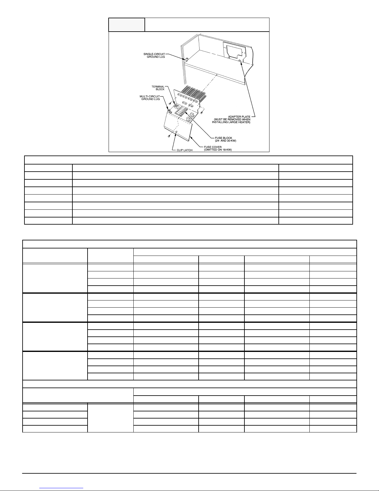
Figure 1
Installing The Electric Heat Accessory
Table 1 − Accessory Heater Usage
Part Number Description Use with Model Sizes
EHC09AKCN3 9 kW, single phase, no internal circuit protection ALL
EHC15AKF3* 15 kW, single phase, with fuses ALL
EHC15AKB3*† 15 kW, single phase, with circuit breakers ALL
EHC20AKF3* 20 kW, single phase, with fuses ALL
EHC20AKB3*† 20 kW, single phase, with circuit breakers ALL
EHC25AHCF3 24 kW, supplied as 3 phase, field convertible to single phase, with fuses 48 − 60
EHC30AHCF3 30 kW, supplied as 3 phase, field convertible to single phase, with circuit breakers 48 − 60
† EHC15AKB3 & EHC20AKB3 are not approved for use in Canada (must use fused heaters and certified single point wiring kit).
* 15kW & 20kW are not recommended for specific heat pump applications, see AIRFLOW DELIVERY (CFM)
HEAT PUMP MINIMUM CFM WHEN USING ELECTRIC HEAT (CFM)
FCM
Model Size
24
36
48
60
Outdoor
Unit Size
18 625 −− −− −−
24 725 875 −− −−
30 875 875 1040 −−
36 970 970 1040 −−
24 875 −− −− −−
30 875 1100 1150 −−
36 975 1100 1225 −−
42 1125 1125 1225 −−
30 875 875 1150 −−
36 975 1100 1225 −−
42 1125 1125 1225 −−
48 1305 1305 1305 1400
36 1100 1350 1350 −−
42 1125 1350 1350 −−
48 1300 1350 1465 1750
60 1625 1625 1750 1750
9 15 20 24, 30
Heater Size kW
A/C MINIMUM CFM WHEN USING ELECTRIC HEAT (CFM)
FCM
Model Size
24
36 700 850 1050 −−
48 700 850 1050 1400
60 1050 1050 1050 1750
NOTES:
1. Heater Only−Air conditioner with electric heater application.
2. These airflows are minimum acceptable airflows as UL listed. Actual airflow delivered will be per airflow delivery chart for Electric Heating
Modes.
Heater Only
9 15 20 24, 30
625 725 875 −−
Heater Size kW
482 01 2231 02
Specifications are subject to change without notice
2
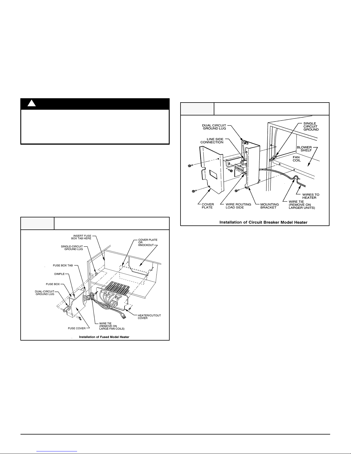
ATTACH FUSE BOX OR CIRCUIT BREAKER BOX
1. For 15kW and 20kW fused models:
After installing heater assembly, attach fuse assembly to side of
fan coil unit by inserting fuse box tab between insulation and to
left side of unit and fan deck. Mount front of assembly to side
flange with two (2) screws provided. On fan coil units size 4200
and larger, remove wire tie that shortens wire length between
heater and fuses. Fuse cover is closed by engaging dimples in
fuse box. (See Figure 2)
2. For 24kW and 30kW fused models:
Fuse assembly is mounted on heater. Be sure fuse cover is
closed by engaging clip latch on unit top panel. (See Figure 1)
Connect heater wiring harness plug to receptacle on fan control
board or wire harness. A positive connection must be made
between plug and receptacle. Plug will interlock with receptacle
when properly seated. Harness contains both 24V control and
high−voltage wiring. Blower power is provided through heater
harness.
NOTE: Units with or without electric heaters require a minimum
CFM. Refer to unit wiring label to ensure the fan speed selected with
electric heaters is equal to or greater than the minimum fan speed
indicated. The minimum CFM for cooling is determined by the
outdoor unit requirements. Use the higher of the two for year−round
operation.
!
ELECTRICAL SHOCK.
Failure to follow this warning could result in death and/or
personal injury.
Close fuse box before power is turned to ON position.
3. For 5kW through 20kW circuit breaker models:
After installing heater assembly, attach circuit breaker assembly
to unit with screws provided. (See Figure. 3) On fan coil units
size 4200 and larger, remove wire tie that shortens wire length
between heater and circuit breaker assembly to allow mounting
of circuit breaker assembly. (See Figure 3)
4. Circuit breaker models require installing a bezel in unit door to
provide safe access to circuit breakers. Bezel mounts on inside
of blower door. (See Figure 4)
WARNING
Figure 2 Fused Model Installation
a. Cut insulation away from access hole in blower access panel.
Slide bezel flanges under insulation. Lip on bezel must protrude
inward toward unit.
b. Secure bezel to panel with two (2) No. 6 hex head screws. Insert
screws through original cover plate holes on access panel and
drive into engagement holes on bezel flanges.
ELECTRICAL CONNECTIONS
Refer to unit instructions for recommended wiring procedures.
Install wiring in accordance with all applicable local and national
codes.
Figure 3 Circuit Breaker Model Installation
A. Wire 24V Control Systems
1. Connections to unit
Use No. 18 AWG color−coded, insulated (35 Deg. C minimum)
wire to make low−voltage connections between thermostat, fan
coil unit, and outdoor unit. If thermostat is located more than 100
ft. from unit (as measured along the low−voltage wire), use No.
16 AWG color−coded, insulated (35 Deg. C minimum) wire. All
wiring must be separated from line voltage power leads. Refer
to outdoor unit wiring instructions for additional wiring procedure
recommendations.
2. Transformer
Transformer is factory wired for 230V operation. For 208V applications, disconnect black wire on transformer 230V terminal
and reconnect it to 208V terminal. (See Figure 5) The secondary
circuit of transformer is protected by a 5−amp fuse mounted on
fan control board.
3. Heater staging
The units are shipped circuited for single stage operation and
the Observer Wall Control only supports single stage operation.
4. Rectifier and Time Delay Boards
Each heater element is controlled by a relay mounted on the
heater panel. The relay has a 24V DC coil. Each relay has a
small rectifier board attached directly to relay coil terminals. The
rectifier board converts incoming 24V AC control signal to DC.
Some heaters may have up to three relays. These relays are for
future use with a control capable of staging the electric heat. The
second and/or third relay rectifier board also has a time delay
feature and a small jumper wire built into it. With the jumper uncut, the time delay allows the second stage heat to be energized
approximately five (5) seconds after the first stage. On 24kW,
3
Specifications are subject to change without notice
482 01 2231 02
 Loading...