

HVAC Partners 801S, 80DSS, 801P, 80DSP Installation Instructions Manual
ISO 9001:2008
INSTALLATION INSTRUCTIONS
FOR DOWNFLOW SINGLE STAGE GAS FURNACES
(-)801S DOWNFLOW SERIES
(-)801P DOWNFLOW SERIES
(-)(-)80DSS DOWNFLOW SERIES
(-)(-)80DSP DOWNFLOW SERIES
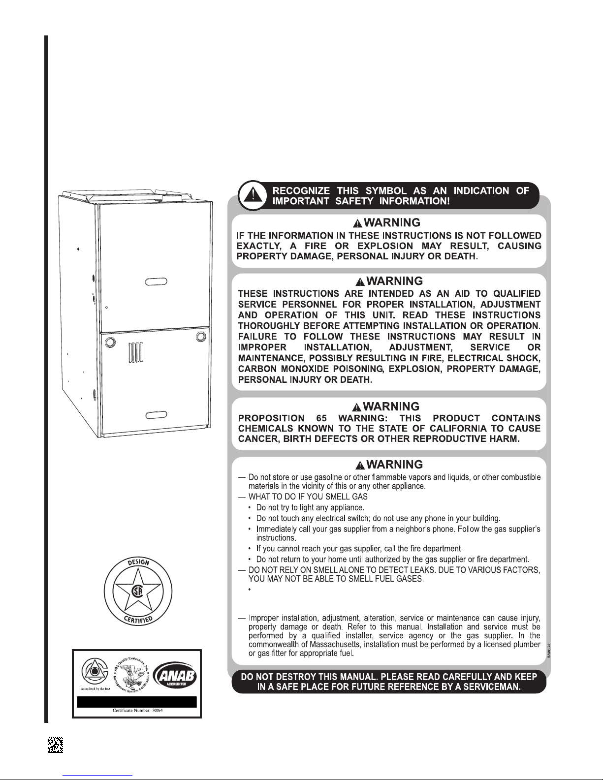
U.L. and/or C.S.A. recognized fuel gas and CO (carbon monoxide) detectors are recommended in all applications, and their installation should be in accordance with the
manufacturer’s recommendations and/or local laws, rules, regulations, or customs.
Factory Use Only
92-24161-143-01
SUPERSEDES 92-24161-143-00

TABLE OF CONTENTS
1 TABLE OF CONTENTS. . . . . . . . . . . . . . . . . . . . . . . 2
2 GENERAL INFORMATION . . . . . . . . . . . . . . . . . . . . 3
Receiving . . . . . . . . . . . . . . . . . . . . . . . . . . . . . . . . . . 4
Contents
California Proposition 65 Note . . . . . . . . . . . . . . . . . . 4
Checklist . . . . . . . . . . . . . . . . . . . . . . . . . . . . . . . . . . . 5
3 SAFETY INFORMATION. . . . . . . . . . . . . . . . . . . . . . 6
Warnings. . . . . . . . . . . . . . . . . . . . . . . . . . . . . . . . . . . 6
Important Information About Efficiency and Quality. . 7
4 LOCATION REQUIREMENTS . . . . . . . . . . . . . . . . . 8
Site Selection . . . . . . . . . . . . . . . . . . . . . . . . . . . . . . . 8
Clearance – Accessibility . . . . . . . . . . . . . . . . . . . . . . 8
Upflow Dimensions & Clearance Table . . . . . . . . . . . 9
5 DUCTING . . . . . . . . . . . . . . . . . . . . . . . . . . . . . . . . . 10
Downflow Installations . . . . . . . . . . . . . . . . . . . . . . . 10
6 COMBUSTION AND VENTILATION AIR . . . . . . . . 12
Combustion Air Requirements . . . . . . . . . . . . . . . . . 12
Venting . . . . . . . . . . . . . . . . . . . . . . . . . . . . . . . . . . . 16
“B-1” Vertical Venting . . . . . . . . . . . . . . . . . . . . . . . . 16
Special Vent Systems (SVS) . . . . . . . . . . . . . . . . . . 17
Power Vent Systems . . . . . . . . . . . . . . . . . . . . . . . . 18
Existing Vent Systems . . . . . . . . . . . . . . . . . . . . . . . 18
7 GAS SUPPLY. . . . . . . . . . . . . . . . . . . . . . . . . . . . . . 19
Gas Supply and Piping. . . . . . . . . . . . . . . . . . . . . . . 19
Gas Piping . . . . . . . . . . . . . . . . . . . . . . . . . . . . . . . . 20
Gas Pressure . . . . . . . . . . . . . . . . . . . . . . . . . . . . . . 21
Setting Gas Pressure . . . . . . . . . . . . . . . . . . . . . . . . 22
9 ELECTRICAL WIRING . . . . . . . . . . . . . . . . . . . . . . 23
Reversing the Electrical Connection . . . . . . . . . . . . 23
Thermostat . . . . . . . . . . . . . . . . . . . . . . . . . . . . . . . . 24
8 LP CONVERSION . . . . . . . . . . . . . . . . . . . . . . . . . . 25
10 ACCESSORIES . . . . . . . . . . . . . . . . . . . . . . . . . . . . 26
Field Installed Option Accessories. . . . . . . . . . . . . . 26
Humidifier . . . . . . . . . . . . . . . . . . . . . . . . . . . . . . . . . 26
4-Inch Flue Adapter . . . . . . . . . . . . . . . . . . . . . . . . . 26
Filters . . . . . . . . . . . . . . . . . . . . . . . . . . . . . . . . . . . . 26
RXGW-B01 Chimney Adapter . . . . . . . . . . . . . . . . . 26
11 TWINNING . . . . . . . . . . . . . . . . . . . . . . . . . . . . . . . . 27
Furnace Twinning Installations. . . . . . . . . . . . . . . . . 27
Control Boards . . . . . . . . . . . . . . . . . . . . . . . . . . 28-29
12 HIGH ALTITUDE . . . . . . . . . . . . . . . . . . . . . . . . . . . 30
Natural Gas at High Altitudes . . . . . . . . . . . . . . . . . . 30
LP Gas at High Altitudes. . . . . . . . . . . . . . . . . . . . . . 32
13 STARTUP PROCEDURES . . . . . . . . . . . . . . . . . . . 33
Sequence of Operation . . . . . . . . . . . . . . . . . . . . . . 33
14 DIAGNOSTICS & FAULT CODES . . . . . . . . . . . . . 34
15 LOCKOUT . . . . . . . . . . . . . . . . . . . . . . . . . . . . . . . . 35
16 FIELD SELECTIONS & ADJUSTMENTS . . . . . . . 36
Field Selections – Dipswitches. . . . . . . . . . . . . . . . . 36
17 FAULT CLEAR. . . . . . . . . . . . . . . . . . . . . . . . . . . . . 37
18 FAULT RECALL. . . . . . . . . . . . . . . . . . . . . . . . . . . . 37
19 FLAME STATUS L.E.D.. . . . . . . . . . . . . . . . . . . . . . 37
20 TIMING DIAGRAM. . . . . . . . . . . . . . . . . . . . . . . . . . 37
21 ADJUSTING OR CHECKING FURNACE INPUT . 38
22 SETTING INPUT RATE . . . . . . . . . . . . . . . . . . . . . . 39
23 AIRFLOW . . . . . . . . . . . . . . . . . . . . . . . . . . . . . . . . . 40
Blower Speed Selection . . . . . . . . . . . . . . . . . . . . . . 41
24 SAFETY FEATURES. . . . . . . . . . . . . . . . . . . . . . . . 42
25 MAINTENANCE. . . . . . . . . . . . . . . . . . . . . . . . . . . . 43
Gas Furnace (Direct Drive) Instructions. . . . . . . . . . 43
Filters . . . . . . . . . . . . . . . . . . . . . . . . . . . . . . . . . . . . 43
Lubrication . . . . . . . . . . . . . . . . . . . . . . . . . . . . . . . . 43
26 SYSTEM OPERATION INFORMATION . . . . . . . . . 44
27 ANNUAL INSPECTION . . . . . . . . . . . . . . . . . . . . . . 45
28 REPLACEMENT PARTS. . . . . . . . . . . . . . . . . . . . . 45
24 DIAGNOSTICS. . . . . . . . . . . . . . . . . . . . . . . . . . . . . 46
30 WIRING DIAGRAM . . . . . . . . . . . . . . . . . . . . . . . . . 47
IMPORTANT: TO INSURE PROPER INSTALLATION AND OPERATION OF THIS PRODUCT, COMPLETELY READ ALL INSTRUCTIONS PRIOR TO ATTEMPTING TO ASSEMBLE, INSTALL, OPERATE, MAINTAIN OR REPAIR THIS PRODUCT. UPON UNPACKING
OF THE FURNACE, INSPECT ALL PARTS FOR DAMAGE PRIOR TO INSTALLATION AND START-UP.
2
GENERAL INFORMATION
1.
2.
3.
4.
5.
6.
7.
8.
9.
10.
11.
12.
13.
14.
15.
16.
17.
18.
19.
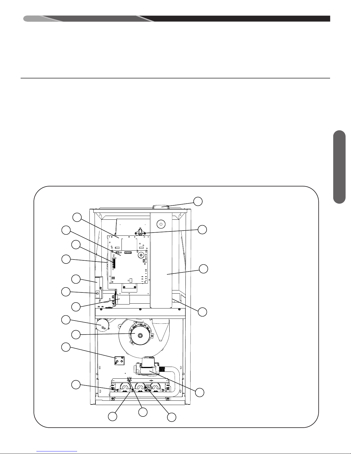
JUNCTION BOX
DOOR SWITCH
CAPACITOR
MAIN PRESSURE SWITCH
INDUCED DRAFT BLOWER (IDB)
MAIN LIMIT
BURNER
FLAME SENSOR
OVER T EMPERATURE SWI TCH
IGNITOR GAS VALVE
GAS VALVE
TRANSFORMER
FLUE PIPE ENCLOSURE
HEAT ASSISTED LIMIT CONTROL (HALC)
FLUE CONNECTION
CONTROL MOUNTING PLATE
FURNACE CONTROL
LOW V OLTAGE TERMINAL
BLOWER
16
17
18
19
1
2
3
4
5
6
7
8
11
9
10
12
13
14
15
ST-A1220-13-X0
NOTE: A heat loss calculation should be performed to properly
determine the required furnace BTU size for the structure. Also,
the duct must be properly designed and installed for proper airflow. Existing ductwork must be inspected for proper size and to
make sure that it is properly sealed. Proper airflow is necessary
for both user comfort and equipment performance.
Before opening the furnace carton, verify that the data tags on
the carton specify the furnace model number that was ordered
from the distributor and are correct for the installation. If not,
return the unit without opening the carton. If the model number
is correct, open the carton and verify that the furnace rating
label specifies the same furnace model number that is specified on the carton label. If the model numbers do not match, return the furnace to the distributor.
IMPORTANT: Proper application, installation and maintenance of
this furnace and system is a must if consumers are to receive the full
benefits for which they have paid.
FIGURE 1
FURNACE COMPONENTS
The (-)801S/(-)801P series furnaces are design certified by CSA
for use with natural and propane gases as follows:
As a Category I furnace, it may be vented vertically with type B1 vent pipe and also may be common vented as described in
these instructions.
This furnace should be installed in accordance with the American
National Standard Z223.1 - latest edition booklet entitled “National
Fuel Gas Code” (NFPA 54), and the requirements or codes of the
local utility or other authority having jurisdiction including local
plumbing or waste water codes.
With the introduction of higher efficiency furnaces, special attention
must be paid to the venting system. Only listed venting systems
may be used as stated in the installation instructions and the Na-
tional Fuel Gas Code, ANSI Z223.1 (NFPA 54),. Since furnace
technology and venting requirements are changing, awareness of
local, state, and federal codes and industry changes is imperative.
General Information
ST-A1220-13-X0
3

GENERAL INFORMATION (cont.)
Install this furnace in accordance with the American National Standard Z223.1 – latest edition entitled “National Fuel Gas Code”
NFPA54) and requirements or codes of the local utilities or other
(
authorities having jurisdiction. This is available from the following:
National Fire Protection Association, Inc.
Batterymarch Park
General Information
Quincy, MA 02269
RECEIVING
Immediately upon receipt, all cartons and contents should be inspected for transit damage. Units with damaged cartons should
be opened immediately. If damage is found, it should be noted on
the delivery papers, and a damage claim filed with the last carrier.
• After unit has been delivered to job site, remove carton taking
care not to damage unit.
• Check the unit rating plate for unit size, electric heat, coil, voltage, phase, etc. to be sure equipment matches what is required for the job specification.
• Read the entire instructions before starting the installation.
• Some building codes require extra cabinet insulation and gasketing when unit is installed in attic applications.
• If installed in an unconditioned space, apply caulking around
the power wires, control wires, refrigerant tubing and condensate line where they enter the cabinet. Seal the power wires on
the inside where they exit conduit opening. Caulking is required to prevent air leakage into and condensate from forming
inside the unit, control box, and on electrical controls.
• Install the unit in such a way as to allow necessary access to
the coil/filter rack and blower/control compartment.
• Install the unit in accordance with any local code which may
apply and the national codes. Latest editions are available
from: “National Fire Protection Association, Inc., Batterymarch
Park, Quincy, MA 02269.” These publications are:
• ANSI/NFPA No. 70-(Latest Edition) National Electrical Code.
• NFPA90A Installation of Air Conditioning and Ventilating Systems.
• NFPA90B Installation of warm air heating and air conditioning
systems.
• The equipment has been evaluated in accordance with the
Code of Federal Regulations, Chapter XX, Part 3280.
CALIFORNIA RESIDENTS ONLY
IMPORTANT: All manufacturer products meet current Federal
OSHA Guidelines for safety. California Proposition 65 warnings
are required for certain products, which are not covered by the
OSHA standards.
California's Proposition 65 requires warnings for products sold in
California that contain, or produce, any of over 600 listed chemicals known to the State of California to cause cancer or birth defects such as fiberglass insulation, lead in brass, and combustion
products from natural gas.
All “new equipment” shipped for sale in California will have labels
stating that the product contains and/or produces Proposition 65
chemicals. Although we have not changed our processes, having
the same label on all our products facilitates manufacturing and
shipping. We cannot always know “when, or if” products will be
sold in the California market.
You may receive inquiries from customers about chemicals found
in, or produced by, some of our heating and air-conditioning equipment, or found in natural gas used with some of our products.
Listed below are those chemicals and substances commonly associated with similar equipment in our industry and other manufacturers.
• Glass Wool (Fiberglass) Insulation
• Carbon Monoxide (CO)
• Formaldehyde
• Benzene
More details are available at the Websites for OSHA (Occupational Safety and Health Administration), at www.osha.gov
State of California's OEHHA (Office of Environmental Health Hazard Assessment), at www.oehha.org.
portant since the chemicals and substances on the list are found
in our daily lives. Most consumers are aware that products present safety and health risks, when improperly used, handled and
maintained.
Consumer education is im-
and the
4

Installation Instructions remain with the furnace as a reference guide to the servicing contractor. We recommend
that performance and installation data be recorded for future reference on this sheet to meet service and warranty
bligations so that job site information is available when required.
o
Installation Checklist
REFER TO INSTALLATION INSTRUCTIONS
GAS SUPPLY
______ Correct pipe size (record size)
______ Correct supply pressure (during furnace operation) (record pressure)
______ Manifold pressure (record upstream pressure)
______ No gas leaks
______ L.P. Kit Number (if applicable) (record kit number)
ELECTRICAL
______ 115 V.A.C. supply (Dedicated Circuit) (record voltage)
______ Polarity observed
______ Furnace properly grounded
Checklist
______ Correct wire size (record type and gauge)
FURNACE INSTALLATION
______ Correct clearance to combustibles (record clearance)
______ Correct clearance for service (at front) (record clearance)
DUCT STATIC PRESSURE
______ in. w.c. on heating speed (record static pressure)
______ in. w.c. on cooling speed (record static pressure)
______ Air temperature rise in heat (record air temperature rise)
______ Air temperature rise in cool (record air temperature rise)
VENTING
______ Correct vent pipe diameter and length (according to NFGC tables) _________________ Vent connection size
______ Correct venting material (according to NFGC tables)
______ Correct lining for masonry chimneys
______ Adequate clearance from combustibles
______ Proper negative pressure reading in the vent
______ Vent pipe secured to induced draft blower housing
COMBUSTION AIR
______ Proper source of combustion air
______ Correct combustion air opening size
______ Optional attic combustion air pull
______ Non-attic combustion air pull
5
SAFETY INFORMATION
WARNING
!
DO NOT INSTALL THIS FURNACE IN A MOBILE HOME!!
THIS FURNACE IS NOT APPROVED FOR INSTALLATION
IN A MOBILE HOME. DOING SO COULD CAUSE FIRE,
PROPERTY DAMAGE, PERSONAL INJURY OR DEATH.
WARNING
!
INSTALL THIS FURNACE ONLY IN A LOCATION AND POSITION AS SPECIFIED IN THE LOCATION REQUIREMENTS AND CONSIDERATIONS SECTION OF THESE
INSTRUCTIONS.
WARNING
!
IMPROPER INSTALLATION CAN RESULT IN UNSATISFACTORY OPERATION AND/OR DANGEROUS CONDITIONS
AND ARE NOT COVERED BY THE MANUFACTURER’S
WARRANTY.
WARNING
!
DO NOT BYPASS, JUMPER, OR REMOVE ANY SAFETY
SWITCH FROM THE FURNACE CONTROL CIRCUIT. IF A
SAFETY SWITCH CAUSES THE FURNACE TO SHUT
DOWN OR OPERATE INTERMITTENTLY, IT IS AN INDICATION OF A POTENTIAL SAFETY HAZARD THAT MUST BE
ADDRESSED BY A QUALIFIED TECHNICIAN, SERVICE
AGENCY OR THE GAS SUPPLIER. DO NOT RESET
SAFETY CONTROLS WITHOUT CORRECTIVE ACTION
Safety Information
AND/OR VERIFICATION OF PROPER SAFE OPERATION
BY A QUALIFIED INSTALLER, SERVICE AGENCY OR THE
GAS SUPPLIER.
REPLACE ANY SAFETY CONTROL COMPONENT ONLY
WITH IDENTICAL OEM REPLACEMENT PARTS. WHEN A
NEW SAFETY SWITCH IS INSTALLED, IT MUST BE
TESTED FOR A MINIMUM OF 15 MINUTES WITH THE
FURNACE OPERATING AT MAXIMUM INPUT RATE AND
WITH BOTH BLOWER AND BURNER DOOR INSTALLED.
IF THE FURNACE IS INSTALLED IN A CLOSET, THE
CLOSET DOOR MUST ALSO BE CLOSED FOR THIS
TEST. REPEAT THE TEST AT THE MINIMUM INPUT RATE
IF THE FURNACE IS A MULTI-STAGE FURNACE.
WARNING
!
USE ONLY WITH THE TYPE OF GAS APPROVED FOR THIS
FURNACE. REFER TO THE FURNACE RATING PLATE.
WARNING
!
COMBUSTION AND VENTILATION AIR MUST BE PROVIDED TO THE FURNACE AS REQUIRED BY THE NATIONAL FUEL-GAS CODE (U.S.) AND THE COMBUSTION
AND VENTILATION AIR SECTION OF THESE INSTRUCTIONS.
W
AR
N
IN
N
N
N
M O
N S
PR
E
C
NLY, AS
ECTIO
O
G
T
D
U
TH
C
I
TS
S
SP
N O
FU
MU
F
S
R
N
E
CIFIE
THE
T
A
B
C
E
S
E INS
E
D
T
O
D IN
I
S
C
H
A
A
N
A
P
THE
V
TRUCTIO
R
G
E
PR
OV
ENT P
NS
D
O
U
T
E
D
IPE
.
!
C
O
MB
U
STI
D
O
O
VE
NT S
INST
!
WHEN A FURNACE IS INSTALLED SO THAT SUPPLY
DUCTS CARRY AIR CIRCULATED BY THE FURNACE TO
AREAS OUTSIDE THE SPACE CONTAINING THE FURNACE,
THE RETURN AIR SHALL ALSO BE HANDLED BY DUCT(S)
SEALED TO THE FURNACE CASING AND TERMINATING
OUTSIDE THE SPACE CONTAINING THE FURNACE.
!
DO NOT OPERATE THE SYSTEM WITHOUT FILTERS. A
PORTION OF THE DUST ENTRAINED IN THE AIR MAY
TEMPORARILY LODGE IN THE AIR DUCT RUNS AND AT
THE SUPPLY REGISTERS. ANY CIRCULATED DUST PARTICLES WILL BE HEATED AND CHARRED BY CONTACT
WITH THE FURNACE HEAT EXCHANGER. THIS SOOTY
RESIDUE WILL SOIL CEILINGS, WALLS, DRAPES, CARPETS AND OTHER HOUSEHOLD ARTICLES. SOOT DAMAGE MAY ALSO RESULT WITH, OR WITHOUT, FILTERS IN
PLACE, WHEN CERTAIN TYPES OF CANDLES ARE
BURNED, OR CANDLEWICKS ARE LEFT UNTRIMMED.
!
IN COMPLIANCE WITH RECOGNIZED CODES, IT IS RECOMMENDED THAT AN AUXILIARY DRAIN PAN BE INSTALLED UNDER THIS FURNACE AND ANY INSTALLED
EVAPORATOR COIL THAT IS LOCATED IN ANY AREA OF
A STRUCTURE WHERE DAMAGE TO THE BUILDING OR
BUILDING CONTENTS MAY OCCUR AS A RESULT OF AN
OVERFLOW OF THE A/C COIL DRAIN PAN.
O
R
S
.
C
O
YSTE
ALLA
TIO
WARNING
WARNING
WARNING
-
WARNING
!
NEVER TEST FOR GAS LEAKS WITH AN OPEN FLAME.
USE A COMMERCIALLY AVAILABLE SOAP SOLUTION
MADE SPECIFICALLY FOR THE DETECTION OF LEAKS
TO CHECK ALL CONNECTIONS, AS SPECIFIED IN GAS
SUPPLY AND PIPING SECTION OF THESE INSTRUCTIONS.
6
SAFETY
WARNING
!
BLOWER AND BURNERS MUST NEVER BE OPERATED
WITHOUT THE BLOWER DOOR IN PLACE. THIS IS TO PREVENT DRAWING GAS FUMES (WHICH COULD CONTAIN
HAZARDOUS CARBON MONOXIDE) INTO THE HOME THAT
COULD RESULT IN PERSONAL INJURY OR DEATH.
WARNING
!
ALWAYS INSTALL THE FURNACE TO OPERATE WITHIN
THE FURNACE’S INTENDED TEMPERATURE-RISE
RANGE WITH A DUCT SYSTEM WHICH HAS AN EXTERNAL STATIC PRESSURE WITHIN THE ALLOWABLE
RANGE, AS SPECIFIED IN THE DUCTING SECTION OF
THESE INSTRUCTIONS. SEE ALSO FURNACE RATING
PLATE.
THE FURNACE MAY BE USED FOR HEATING OF BUILDINGS OR STRUCTURES UNDER CONSTRUCTION.
INSTALLATION MUST COMPLY WITH ALL INSTALLATION
INSTRUCTIONS INCLUDING:
PROPER VENT INSTALLATION;
-
FURNACE OPERATING UNDER THERMOSTATCONTROL;
RETURN AIR DUCT SEALED TO THE FURNACE;
-
AIR FILTERS IN PLACE;SET FURNACE INPUT RATE AND TEMPERATURERISE PER RATING PLATE MARKINGS;
MEANS FOR PROVIDING OUTDOOR AIR RE-
-
QUIRED FOR COMBUSTION;
RETURN AIR TEMPERATURE MAINTAINED BE-
-
TWEEN 55°F (13°C) AND 80°F (27°C); AND
CLEAN FURNACE, DUCT WORK AND COMPO-
-
NENTS UPON SUBSTANTIAL COMPLETION OF
THE CONSTRUCTION PROCESS, AND VERIFY
THAT THE FURNACE OPERATING CONDITIONS
INCLUDING IGNITION, INPUT RATE, TEMPERATURE RISE AND VENTING, ACCORDING TO THE
INSTRUCTIONS AND CODES.
WARNING
!
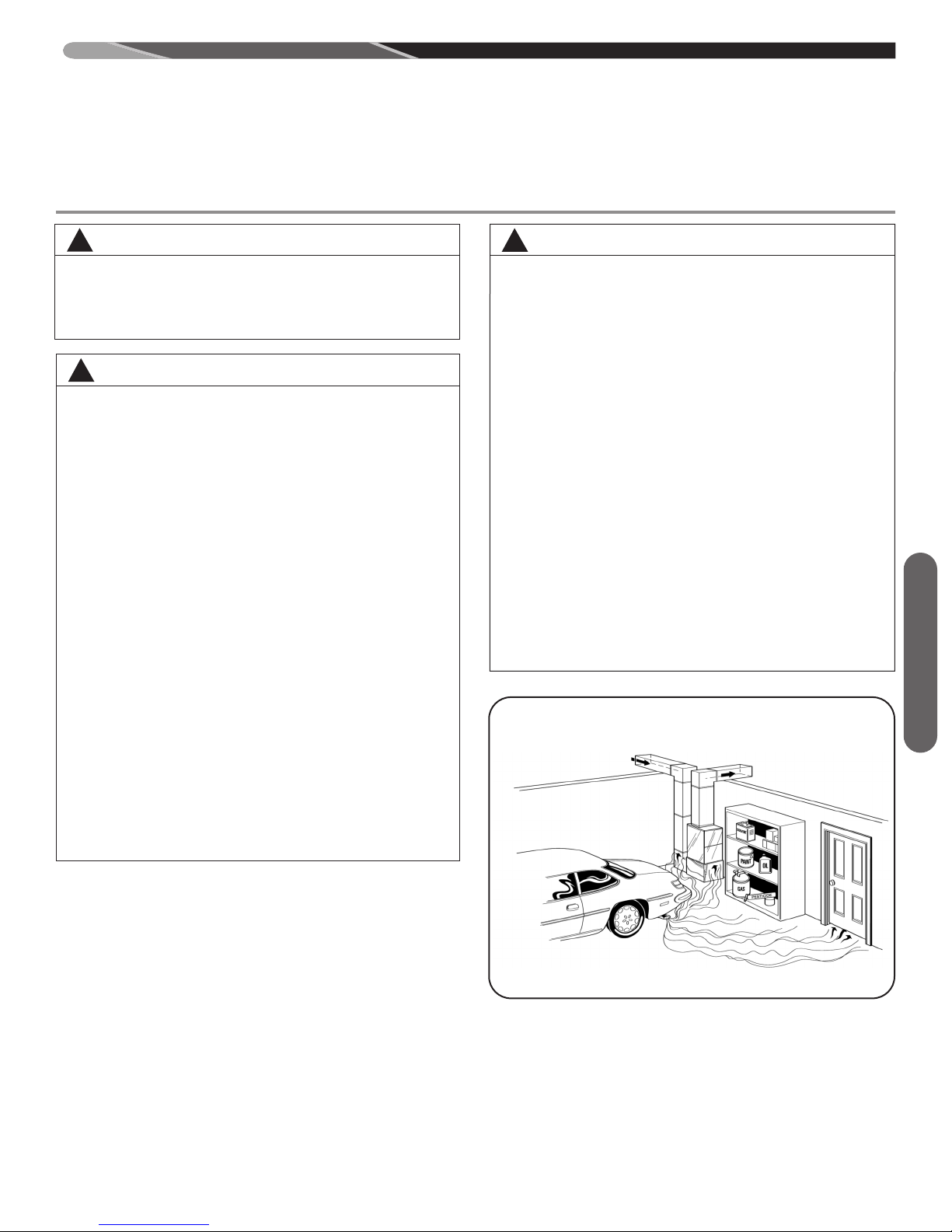
DUCT LEAKS CAN CREATE AN UNBALANCED SYSTEM
AND DRAW POLLUTANTS SUCH AS DIRT, DUST, FUMES
AND ODORS INTO THE HOME CAUSING PROPERTY
AMAGE. FUMES AND ODORS FROM TOXIC, VOLATILE
D
OR FLAMMABLE CHEMICALS, AS WELL AS AUTOMOBILE EXHAUST AND CARBON MONOXIDE (CO), CAN BE
DRAWN INTO THE LIVING SPACE THROUGH LEAKING
DUCTS AND UNBALANCED DUCT SYSTEMS CAUSING
PERSONAL INJURY OR DEATH (SEE FIGURE 2).
• IF AIR-MOVING EQUIPMENT OR DUCTWORK IS LOCATED IN GARAGES OR OFF-GARAGE STORAGE
AREAS - ALL JOINTS, SEAMS, AND OPENINGS IN THE
EQUIPMENT AND DUCT MUST BE SEALED TO LIMIT
THE MIGRATION OF TOXIC FUMES AND ODORS INCLUDING CARBON MONOXIDE FROM MIGRATING
INTO THE LIVING SPACE.
• IF AIR-MOVING EQUIPMENT OR DUCTWORK IS LOCATED IN SPACES CONTAINING FUEL BURNING APPLIANCES SUCH AS WATER HEATERS OR BOILERS ALL JOINTS, SEAMS, AND OPENINGS IN THE EQUIPMENT AND DUCT MUST ALSO BE SEALED TO PREVENT DEPRESSURIZATION OF THE SPACE AND
POSSIBLE MIGRATION OF COMBUSTION BYPRODUCTS INCLUDING CARBON MONOXIDE INTO THE LIVING SPACE.
FIGURE 2
MIGRATION OF DANGEROUS SUBSTANCES, FUMES, AND ODORS INTO
LIVING SPACES
Safety Information
IMPORTANT INFORMATION ABOUT
EFFICIENCY AND INDOOR AIR
QUALITY
Central cooling and heating equipment is only as efficient as the
duct system that carries the cooled or heated air. To maintain efficiency, comfort and good indoor air quality, it is important to have
the proper balance between the air being supplied to each room
and the air returning to the cooling and heating equipment.
Proper balance and sealing of the duct system improves the efficiency of the heating and air conditioning system and improves
the indoor air quality of the home by reducing the amount of airborne pollutants that enter homes from spaces where the ductwork and / or equipment is located. The manufacturer and the
U.S. Environmental Protection Agency’s Energy Star Program
recommend that central duct systems be checked by a qualified
contractor for proper balance and sealing.
Adapted from Residential Duct Diagnostics and Repair, with permission of Air Conditioning
Contractors of America (ACCA).
7
LOCATION REQUIREMENTS
GENERAL INFORMATION
WARNING
!
WHEN THIS FURNACE IS INSTALLED IN A RESIDENTIAL
GARAGE, IT MUST BE INSTALLED SO THE BURNERS
AND IGNITION SOURCE ARE LOCATED NO LESS THAN
18 INCHES [450MM] ABOVE THE FLOOR. THIS IS TO PREVENT THE RISK OF IGNITING FLAMMABLE VAPORS
WHICH MAY BE PRESENT IN A GARAGE. ALSO, THE FURNACE MUST BE LOCATED OR PROTECTED TO AVOID
PHYSICAL DAMAGE BY VEHICLES. FAILURE TO FOLLOW
THESE WARNINGS CAN CAUSE A FIRE OR EXPLOSION,
RESULTING IN PROPERTY DAMAGE, PERSONAL INJURY
OR DEATH.
1. IMPORTANT: If using a cooling evaporator coil with this fur-
nace, be sure the air passes over the heat exchanger before
passing over the cooling coil. The cooled air passing over the
warm ambient air inside the heat exchanger tubes can cause
condensation inside the tubes resulting in corrosion and eventual failure. An auxiliary drain pan should extend under any
evaporator coil installed with the furnace.
If there are manual dampers, they must be equipped to prevent
heating or cooling operation unless the damper is in the full heat
or cool position.
2. NOTE: This furnace is shipped with heat exchanger support
brackets installed under the back of the heat exchanger. These
may be removed before installation, but it is not required.
3. IMPORTANT: This furnace is not approved or recommended
for installation on its back, with access doors facing upwards.
4. This furnace is suitable for installation in buildings constructed
on-site. This heating unit should be centralized with respect to
the heat distribution system as much as practicable.
5. NOTE: These furnaces are approved for installation in attics,
as well as alcoves, utility rooms, closets and crawlspaces.
6. IMPORTANT: Support this unit when installed. Unit may be rein-
stalled on combustible wood floorin if using a supply air plenum.
If not using supply air plenum, a combustible floor base is required. See ducting section of this manual.
7. IMPORTANT: If installing in a utility room, be sure the door is
wide enough to:
Location
a. allow the largest part of the furnace to pass; or
b. allow any other appliance (such as a water heater) to pass.
WARNING
!
THIS FURNACE IS NOT APPROVED OR RECOMMENDED
FOR INSTALLATION ON ITS BACK, WITH ACCESS DOORS
FACING UPWARDS.
SITE SELECTION
1. Select a site in the building near the center of the proposed, or existing, duct system.
2. Give consideration to the vent system piping when selecting the furnace location. Be sure the venting system
can get from the furnace to the termination with minimal
length and elbows.
3. Locate the furnace near the existing gas piping. Or, if
running a new gas line, locate the furnace to minimize
the length and elbows in the gas piping.
4. Locate the furnace to maintain proper clearance to
combustibles as shown in following Figure 3.
WARNING
!
DO NOT LIFT THE UNIT BY THE HEAT EXCHANGER
TUBES. DOING SO CAN DAMAGE THE HEAT EXCHANGER ASSEMBLY.
CLEARANCE – ACCESSIBILITY
The design of forced air furnaces with input ratings as
listed in the tables under Figure 3 are clearances to combustible materials shown in inches.
See name/rating plate and clearance label for specific
model number and clearance information.
Service clearance of at least 24 inches (30 cm) is recommended in front of all furnaces.
NOTE: Use recommended 24” (30 cm) clearance if accessibility clearances are greater than fire protection clearances.
ACCESSIBILITY CLEARANCES, WHERE GREATER, MUST
TAKE PRECEDENCE OVER FIRE PROTECTION CLEARANCES.
WARNING
!
COMBUSTIBLE MATERIAL MUST NOT BE PLACED ON
OR AGAINST THE FURNACE JACKET. THE AREA
AROUND THE FURNACE MUST BE KEPT CLEAR AND
FREE OF ALL COMBUSTIBLE MATERIALS INCLUDING
GASOLINE AND OTHER FLAMMABLE VAPORS AND LIQUIDS. PLACEMENT OF COMBUSTIBLE MATERIALS ON,
AGAINST OR AROUND THE FURNACE JACKET CAN
CAUSE AN EXPLOSION OR FIRE RESULTING IN PROPERTY DAMAGE, PERSONAL INJURY OR DEATH. THE
HOMEOWNER SHOULD BE CAUTIONED THAT THE FURNACE AREA MUST NOT BE USED AS A BROOM CLOSET
OR FOR ANY OTHER STORAGE PURPOSES.
8
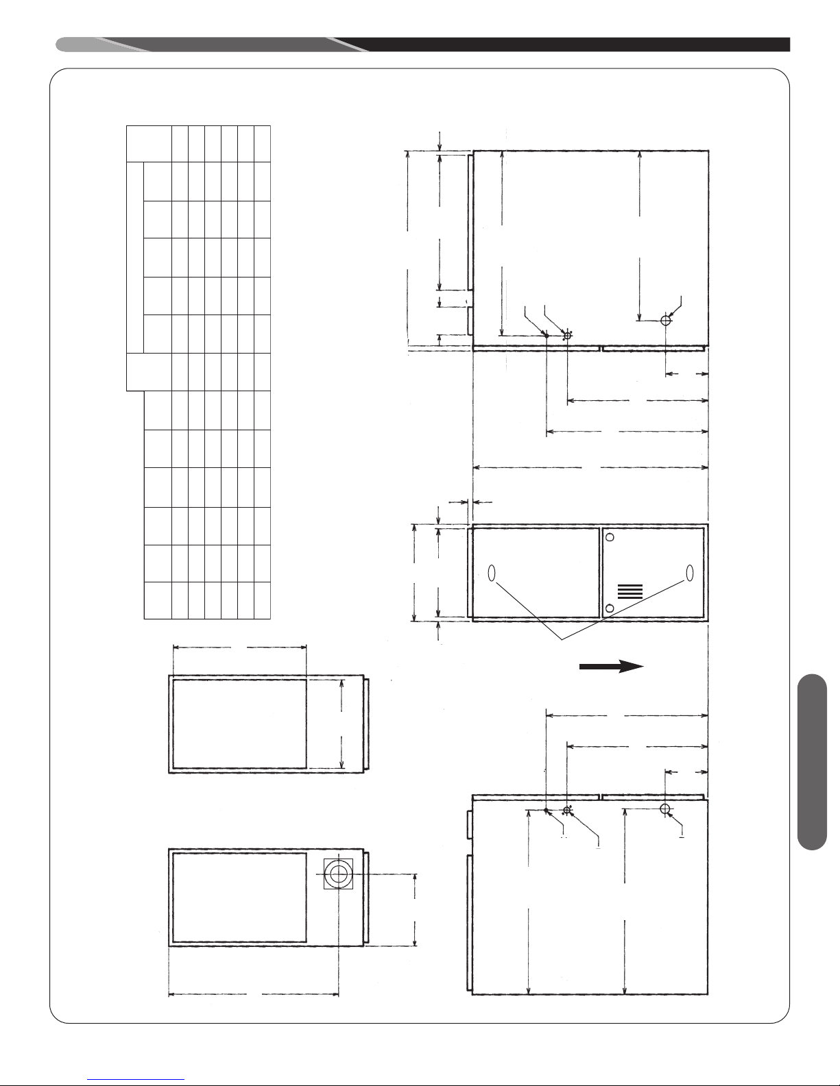
FIGURE 3
DOWNFLOW DIMENSIONS
Ship.
Back Top Front Vent
REDUCED CLEARANCE (IN.)
Left Right
/8
5
/8
1
20
/16
1
28
➀ May require 3” to 4” or 3” to 5” adapter.
➁ May be 0” with type B vent.
➂ May be 1” with type B vent.
/8
5
26
/8 DIA.
/8 DIA.
7
7
/16
7
24
/8 DIA.
5
1
D
/16
3
/8
/8 0 4➁ 0 1 3 6➂ 85 lbs.
/8 0 3➁ 0 1 3 6➂ 105 lbs.
/8 0 3➁ 0 1 3 6➂ 115 lbs.
/8 0 0 0 1 3 6➂ 120 lbs.
/8 0 0 0 1 3 6➂ 140 lbs.
1
5
5
/8 0 0 0 1 3 6➂ 150 lbs.
1
5
5
3
20
/8
3
6
23
/8 ➀ 13
/8 ➀ 16
/8 ➀ 16
/8 ➀ 20
/8 ➀ 23
3
1
1
/32 10
/32 12
/32 12
27
11
11
/2 16
/2 16
1
1
Model A B C D E
05 14 12
CLEARANCE TO COMBUSTIBLE MATERIAL (INCHES)
DOWNFLOW MODELS
Side Side Wgts.
10(A) 17
07 17
/8 ➀ 23
7
5
5
/32 13
/32 15
/32 15
27
11
11
/2 23
/2 23
1
1
10(B) 21 19
12 24
15 24
/4
3
19
/8
5
R.A.
B
A
/8
5
/4
3
SIGHT
34
GLASS
AIRFLOW
S.A.
E
/8
3
23
/8
3
Location
20
/16
3
6
TOP BOTTOM
/2
1
24
/8
5
26
C
LOW VOLTAGE
/16
13
26
GAS CONNECTION
ELECTRIC CONNECTION
NOTE: IN DOWNFLOW CONFIGURATION, OPTIONAL AIR CUTOUT IS NOT PERMITTED.
9
DUCTING
roper air flow is required for the correct operation of this
P
furnace. Restricted air flow can cause erratic operation and
can damage the heat exchanger. The duct system must
carry the correct amount of air for heating and cooling if
summer air conditioning is used.
WARNING
!
SOME HEATING AIRFLOW VALUES MAY BE
HIGHER THAN THOSE REQUIRED FOR COOLING.
BE SURE TO SIZE DUCT FOR THE MAXIMUM POSSIBLE AIRFLOW VALUE.
SIZE AIRFLOW DISTRIBUTION SYSTEM TO ACCEPTABLE INDUSTRY STANDARDS AND METHODS. TOTAL STATIC PRESSURE DROP OF THE AIR
DISTRIBUTION SYSTEM SHOULD NOT EXCEED .8
INCHES W.C. THIS WILL INCLUDE ANY AIR CONDITIONER COIL, AIR FILTRATION SYSTEM, ZONING
SYSTEM, DUCTWORK, ETC. REFER TO ADDED
EQUIPMENT TECHNICAL INFORMATION TO OBTAIN
PRESSURE DROP INFORMATION WHEN EQUIPMENT IS OPERATING AT RECOMMENDED HEATING OR COOLING CFMS.
IMPORTANT: When using outside air, design and adjust
the system to maintain a return air temperature ABOVE
55° F during the heating season.
NOTE: Return air grilles and warm air registers must not
be obstructed or closed.
5. Connect the return air ducting to the return air opening
at the top of the unit. Make the connection air tight to
prevent the migration of toxic fumes and odors including carbon monoxide from migrating into the living
space from an adjacent fuel-burning appliance.
NOTE: In downflow configuration, side return air cut
out is not permitted. Do not take return air from the
back of the unit.
6. If a filter is installed near the furnace, be sure to
have adequate space for installation and removal
of the unit filter.
NOTE: DO NOT take return air from furnace rooms,
garages or cold areas. Avoid return air from utility
rooms, kitchens, laundry rooms and bathrooms.
WARNING
!
BLOWER AND BURNERS MUST NEVER BE OPERATED
WITHOUT THE BLOWER DOOR IN PLACE. THIS IS TO
PREVENT DRAWING GAS FUMES (WHICH COULD CONTAIN HAZARDOUS CARBON MONOXIDE) INTO THE
HOME THAT COULD RESULT IN PERSONAL INJURY OR
DEATH.
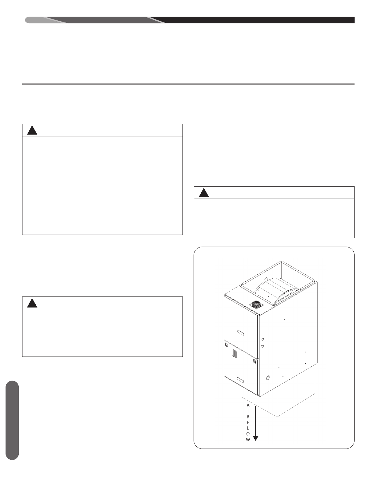
FIGURE 4
DOWNFLOW INSTALLATIONS
WARNING
!
A DOWNFLOW INSTALLATION IS CERTIFIED FOR
INSTALLATION ON A NON-COMBUSTIBLE FLOOR.
USE THE SPECIAL BASE SPECIFIED ON THE FURNACE CLEARANCE LABEL. FAILURE TO INSTALL
THE SPECIAL BASE MAY RESULT IN FIRE, PROPERTY DAMAGE, PERSONAL INJURY OR DEATH.
THIS BASE IS AVAILABLE AS AN ACCESSORY.
1. Position the unit to minimize long runs of duct or runs
of duct with many turns and elbows.
2. If summer air conditioning is desired, position the indoor coil on the supply-air side of the unit. Ensure that
no air can bypass this coil.
3. If installing on a combustible floor and not using an
air conditioning plenum, install the special non-combustible floor base. See Table 1 and Figure 5.
4. Connect the furnace to the supply air plenum. See Figure 4.
Ducting
10
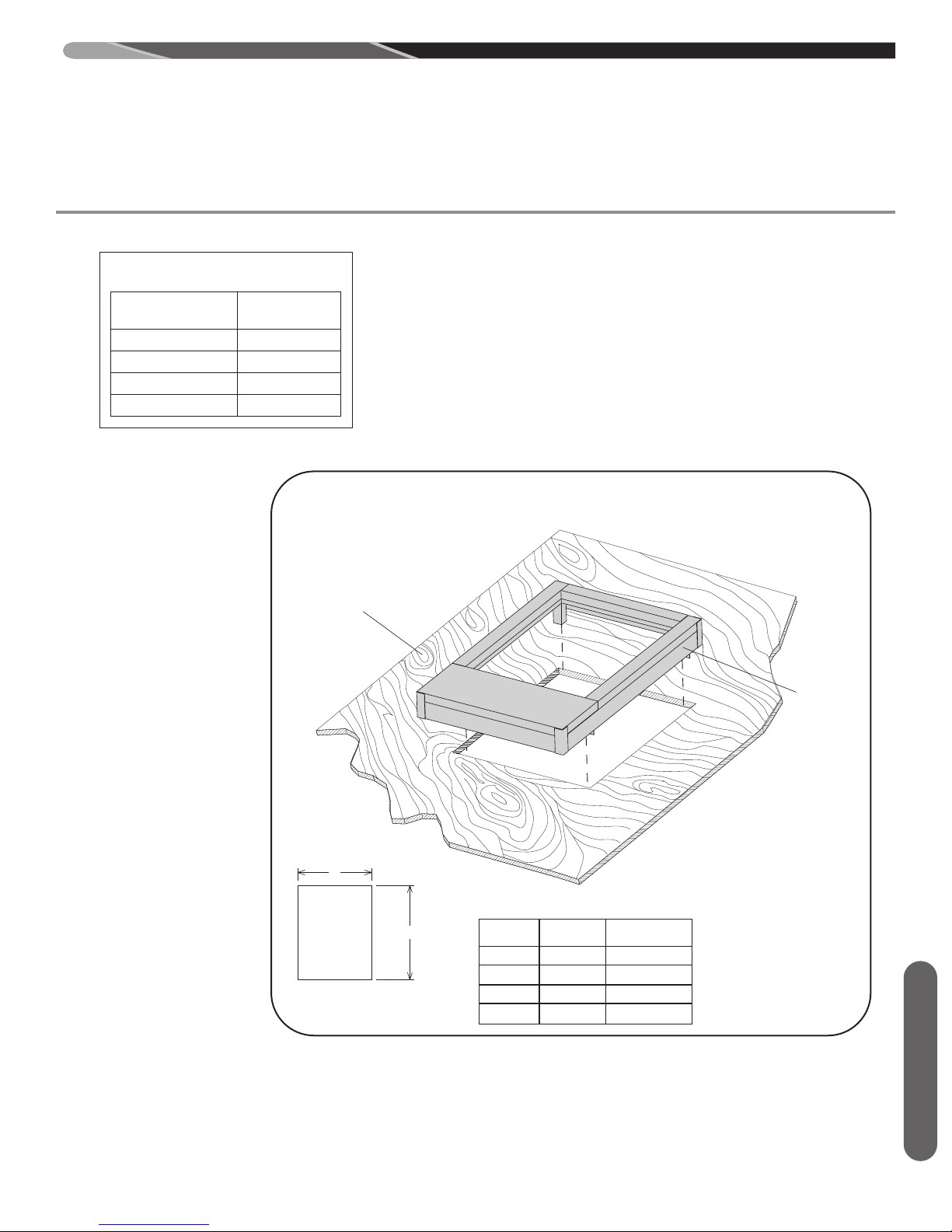
21 5/8"
F
LOOR
M
ATE RIA L
NON-COM
FLOOR BASE
FLOOR CUTOUT
DIMENSIONS
FLOOR
BASE NO.
CABINET
WIDTH
FLOOR CUTOUT
DIMENSION “A”
RXGC-B14
RXGC-B17
RXGC-B21
14.0”
17.5”
21.0”
13.4”
17.0”
20.0”
RXGC-B24
24.5”
23.5”
A
21 5/8"
TABLE 1
ON-COMBUSTIBLE FLOOR BASES
N
Floor Base Size
No. Cabinet
RXGC-B14 14
RXGC-B17 17
RXGC-B21 21
RXGC-B24 24
DUCTING
FIGURE 5
NON-COMBUSTIBLE FLOOR BASE INSTALLATION INSTRUCTIONS
COMBUSTIBLE
FLOOR
MATERIAL
NON-COM-
BUSTIBLE
FLOOR
BASE
FLOOR CUTOUT
DIMENSIONS
ST-A1194-43-00
Ducting
11

COMBUSTION AND VENTILATION AIR
COMBUSTION AIR REQUIREMENTS
IMPORTANT: This is not a direct vent furnace. Review venting
instructions before installing.
WARNING
!
Combustion Air
HIS FURNACE AND ANY OTHER FUEL-BURNING APPLI-
T
ANCE MUST BE PROVIDED WITH ENOUGH FRESH AIR
FOR PROPER COMBUSTION AND VENTILATION OF THE
FLUE GASES. MOST HOMES WILL REQUIRE THAT OUTSIDE AIR BE SUPPLIED INTO THE FURNACE AREA. FAILURE TO DO SO CAN CAUSE DEATH FROM CARBON
MONOXIDE POISONING.
WARNING
!
ADEQUATE FACILITIES FOR PROVIDING AIR FOR COMBUSTION AND VENTILATION MUST BE PROVIDED IN ACCORDANCE WITH SECTION 5.3, AIR FOR COMBUSTION
AND VENTILATION, OF THE NATIONAL FUEL GAS CODE,
ANSI, Z223.1 LATEST EDITION OR APPLICABLE PROVISIONS FOR THE LOCAL BUILDING CODES, AND NOT
OBSTRUCTED SO AS TO PREVENT THE FLOW OF AIR TO
THE FURNACE.
1. IMPORTANT: Air for combustion and ventilation must not
come from a corrosive atmosphere. Any failure due to corrosive elements in the atmosphere is excluded from warranty
coverage.
2. Combustion air must be free of acid forming chemicals; such
as sulphur, fluorine and chlorine. These elements are found in
aerosol sprays, detergents, bleaches, cleaning solvents, air
fresheners, paint and varnish removers, refrigerants and many
other commercial and household products. Vapors from these
products when burned in a gas flame form acid compounds.
The acid compounds increase the dew point temperature of
the flue products and are highly corrosive after they condense.
3. The following types of installation may require OUTDOOR AIR
for combustion, due to chemical exposures:
• Commercial buildings
• Buildings with indoor pools
• Furnaces installed in laundry rooms
• Furnaces in hobby or craft rooms
• Furnaces installed near chemical storage areas.
4. If combustion air is exposed to the following substances (but
not limited to the following), it should not be used and the furnace may require outdoor air for combustion.
• Permanent wave solutions
• Chlorinated waxes and cleaners
• Chlorine-based swimming pool chemicals
• Water softening chemicals
• De-icing salts or chemicals
• Carbon tetrachloride
• Halogen type refrigerants
• Cleaning solvents (such as perchloroethylene)
• Printing inks, paint removers, varnishes, etc.
• Hydrochloric acid
• Cements and glues
• Antistatic fabric softeners for clothes dryers
• Masonry curing and acid washing materials
WARNING
!
ALL FURNACE INSTALLATIONS MUST COMPLY WITH
THE NATIONAL FUEL GAS CODE AND LOCAL CODES TO
PROVIDE ADEQUATE COMBUSTION AND VENTILATION
AIR FOR THE FURNACE. FAILURE TO DO SO CAN CREATE HAZARDOUS CONDITIONS RESULTING IN PROPERTY DAMAGE, BODILY INJURY OR DEATH FROM
SMOKE, FIRE OR CARBON MONOXIDE.
Combustion air requirements are determined by whether
the furnace is in an open (unconfined) area or in a confined space such as a closet or small room.
When the furnace is installed in the same space with other
gas appliances, such as a water heater, be sure there is an
adequate supply of combustion and ventilation air for the
furnace and the other appliances. Do not delete or reduce
the combustion air supply required by the other gas appliances in this space. See Z223.1, National Fuel Gas Code
(NFPA 54). An unconfined space must have at least 50
cubic feet (volume) for each 1,000 BTUH of the total input of
all appliances in the space. If the open space containing the
appliances is in a building with tight construction (contemporary construction), outside air may still be required for the
appliances to burn and vent properly. Outside air openings
should be sized the same as for a confined space.
IMPORTANT: ONLY THE CURRENT VENT INSTRUCTIONS APPLY. All gas furnaces cannot be common-
vented.
OVERTEMPERATURE SAFETY
SWITCHES
Furnaces are equipped with safety switches in the burner
compartment to protect against over-temperature conditions caused by inadequate combustion air supply. The
switches are located in the burner compartment. If a switch
is tripped it must be manually reset after clearing the fault
condition which caused it to open.
WARNING
!
Y
T
E
F
A
S
Y
N
A
E
V
O
M
E
R
R
O
,
R
E
P
M
U
J
,
S
S
A
P
Y
B
T
O
N
O
D
C
T
I
W
S
T
E
F
A
S
N
W
O
D
O
N
O
I
T
E
R
D
D
A
C
N
E
G
A
T
E
F
A
S
O
/
D
N
A
Q
A
Y
B
S
S
A
G
A
L
P
E
R
T
N
E
D
I
M
O
R
F
H
Y
Y
R
U
C
C
I
C
T
I
W
S
E
P
O
R
O
T
O
P
A
F
B
D
E
S
S
H
T
R
O
Y
T
N
O
C
F
I
R
E
V
E
I
F
I
L
A
U
R
E
I
L
P
P
Y
N
A
E
E
O
L
A
U
F
E
H
T
U
A
C
H
I
E
T
A
R
L
A
I
T
N
E
U
Q
A
Y
S
A
G
E
W
S
L
O
R
N
O
I
T
A
C
I
T
S
N
I
D
.
T
E
F
A
S
L
P
E
R
M
E
C
A
N
R
E
H
T
S
E
S
N
A
A
Y
I
M
R
E
T
T
E
F
A
S
D
E
I
F
I
L
I
L
P
P
U
S
T
U
O
H
T
I
R
P
F
O
,
R
E
L
L
T
N
O
C
E
M
E
C
A
R
T
N
O
C
T
O
S
R
N
A
N
R
U
F
Y
L
T
N
E
T
R
A
Z
A
H
Y
T
E
I
N
H
C
E
O
D
.
R
E
R
R
O
C
A
S
R
E
P
E
C
I
V
R
E
O
C
L
O
T
R
A
P
T
C
R
I
C
L
O
M
S
O
T
E
C
,
C
N
C
S
N
A
S
I
T
I
T
A
H
T
D
E
S
,
N
A
I
S
E
R
T
O
A
E
V
I
T
E
P
O
E
F
C
N
E
G
A
N
E
N
O
P
.
Y
L
N
O
A
F
I
.
T
I
U
T
U
H
I
M
R
E
T
C
A
R
Y
T
-
A
C
I
D
N
E
B
T
S
U
E
C
I
V
T
N
O
I
N
O
I
T
E
H
T
R
O
H
T
I
W
12

COMBUSTION AND VENTILATION AIR (cont.)
TABLE 7: MINIMUM SPACE REQUIREMENTS
FOR UNCONFINED SPACE, NON-DIRECT VENT*
Input
(BTUH)
Minimum
Space
(Cubic Ft)
Minimum Area
with 8
Ceilings (sq )
Typical Room
Size w/ 8'
Ceilings ( x )
50,000
2,500
313
16 x 20
75,000
3,750
470
24 x 20
100,000
5,000
625
32 x 20
125,000
6,300
790
36 x 30
150,000 7,500 940 32 x 30
TABLE 8: MINIMUM FREE AREA
OPENING REQUIRED FOR A
FURNACE LOCATED IN A
CONFINED SPACE USING
INDOOR AIR FOR COMBUSTION.
Input (BTUH)
Free Area for Each
Opening (sq inches)
50,000
100
75,000
100
100,000
100
125,000
130
150,000 150
COMBUSTION AIR REQUIREMENTS: CONFINED AND
UNCONFINED SPACES
ARNI
W
!
ALL FURNACE INSTALLATIONS MUST COMPLY WITH
THE NATIONAL FUEL GAS CODE, NFPA 54 AND LOCAL
CODES TO PROVIDE ADEQUATE COMBUSTION AND
VENTILATION AIR FOR THE FURNACE. FAILURE TO DO
SO CAN RESULT IN EXPLOSION, FIRE, PROPERTY DAMAGE, CARBON MONOXIDE POISONING, PERSONAL INJURY OR DEATH.
For improved indoor air quality, added safety and product performance we recommend direct vent type installations. If non-direct type vent system is used, the requirements for combustion
air must be provided as identified in the National Fuel Gas Code.
Combustion air requirements are determined by whether the furnace is in an open (unconfined) area or in a confined space such
as a closet or small room.
WARNING
!
N
A
D
A
E
R
M
T
F
N
S
M
D
A
S
T
N
E
V
L
A
N
O
I
U
O
T
E
A
E
C
A
N
R
E
R
I
D
-
N
I
T
C
U
R
A
F
T
N
E
G
A
M
FURNACE LOCATED IN AN UNCONFINED SPACE
USING INDOOR AIR FOR COMBUSTION:
An unconfined space must have at least 50 cubic feet for each
1,000 BTUH of total input for all appliances in the space. Table 1
below specifies minimum space requirements and a few examples of the room sizes required for different inputs. The sizes are
based on 8-foot ceilings.
If the open space containing the furnace is in a building with tight
construction, outside air may still be required for the furnace to
operate and vent properly. Outside air openings should be sized
the same as for a confined space.
NG
-
E
R
I
U
Q
E
R
G
N
I
T
N
E
V
L
A
R
E
N
E
G
E
H
T
W
O
L
L
O
F
D
N
O
I
,
D
I
U
G
D
G
N
I
T
N
E
L
L
A
T
S
N
I
N
E
V
T
C
T
N
I
S
N
E
,
E
R
U
O
S
R
E
P
S
E
N
I
L
E
R
I
U
Q
E
R
N
O
I
T
A
L
T
H
Q
N
F
.
)
G
N
I
N
A
M
S
I
E
M
P
I
U
J
N
I
L
A
I
H
T
F
O
T
N
E
M
E
L
C
N
I
(
S
E
R
U
L
I
A
C
L
A
U
M
A
D
T
N
R
O
Y
R
U
U
N
A
M
S
T
R
E
P
S
G
N
I
D
U
O
F
O
T
S
E
R
N
A
P
,
E
G
A
H
T
A
E
D
R
O
F
L
A
G
N
I
N
I
A
T
C
E
R
I
D
W
O
L
L
N
I
T
L
U
R
E
P
O
R
.
-
I
D
D
A
L
L
A
O
T
D
N
A
-
N
I
L
L
A
-
P
I
U
Q
E
Y
T
FURNACE LOCATED IN A CONFINED
SPACE
A confined space is defined as any space for a given furnace input
rating which is smaller than that which is specified in Table 1 as
minimum for an “unconfined” space. If the space is less than that
specified in this table, the space is defined as “confined”.
If the space is small enough to be designated as “confined”, it
must have openings into the space which are located in accordance with the requirements set forth in the following subsections
A and B. Size connected to the heated area or to the outside, and
by the input of ALL
If the confined space is within a building with tight construction,
combustion air must be taken from outdoors or from an area
freely communicating with the outdoors.
A. USING INDOOR AIR FOR COMBUSTION:
IMPORTANT: Air should not be taken from a heated space
with a fireplace, exhaust fan or other device that may produce negative pressure.
If combustion air is taken from the heated area, the openings
must each have at least 100 square inches of free area.
Each opening must have at least one square inch of free
area for each 1,000 BTUH of total input in the space. Table 2
shows some typical examples of openings required for combustion air openings required for a confined space.
TABLE 2: MINIMUM FREE AREA
OPENING REQUIRED FOR A
FURNACE LOCATED IN A
CONFINED SPACE USING
INDOOR AIR FOR COMBUSTION.
appliances in the space.
Combustion Air
TABLE 1: MINIMUM SPACE REQUIREMENTS
FOR UNCONFINED SPACE, NON-DIRECT VENT
B. USING OUTDOOR AIR FOR COMBUSTION:
IMPORTANT: Do not take air from an attic space that is
equipped with power ventilation.
The confined space must communicate with the outdoors in
accordance with Methods 1 or 2 below. The minimum dimension of air openings shall not be less than 3 inches. Where
ducts are used, they shall be of the same cross-sectional
area as the free area of the openings to which they connect.
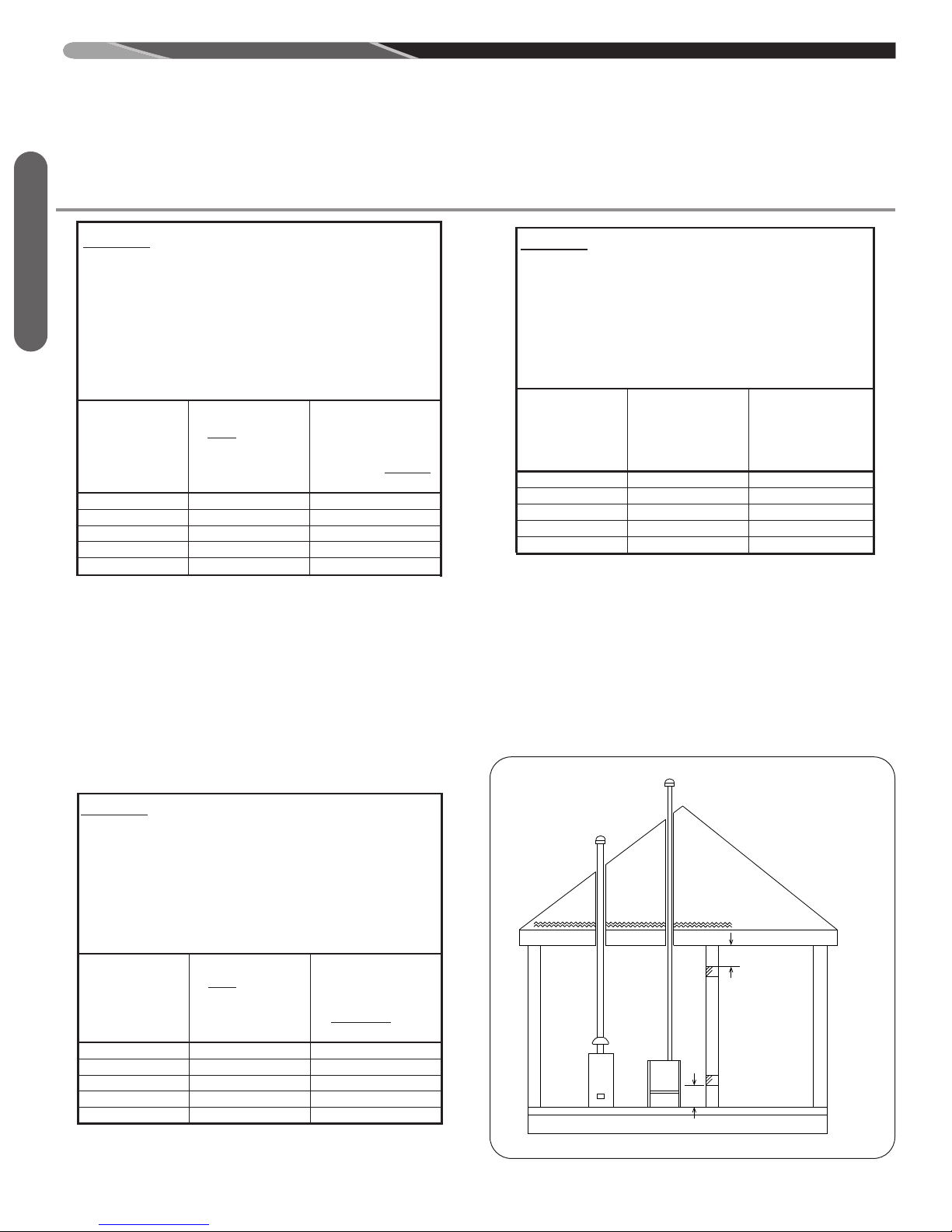
METHOD 1:
Two permanent openings, one located within 12 inches of the
top and one located within 12 inches of the bottom of the enclosure, shall be provided. The openings shall communicate
directly, or by ducts, with the outdoors or spaces (crawl or
attic) that freely communicate with the outdoors.
13
COMBUSTION AND VENTILATION AIR (cont.)
TABLE 9 : MINIMUM FREE AREA REQUIRED
FOR EACH OPENING (WHEN TWO OPENINGS
ARE USED) WITH A FURNACE:
1. LOCATED IN A CONFINED SPACE
2. USING OUTDOOR AIR FOR COMBUSTION
3. COMMUNICATING DIRECTLY TO THE
OUTSIDE THROUGH AN OPENING OR
THROUGH A VERTICAL VENT DUCT.*
Total Input for
ALL Gas
Appliances
(BTUH)
Free Area for
Each Opening
when 2 Separate
Openings are
used (sq inches)
Round Pipe Duct
Diameter (Vercal
Duct Only) (inches)
50,000
13
5
75,000
19
5
100,000
25
6
125,000
32
8
150,000 38 8
TABLE 1 0: MINIMUM FREE AREA REQUIRED
FOR EACH OPENING (WHEN TWO OPENINGS
ARE USED) WITH A FURNACE:
1. LOCATED IN A CONFINED SPACE
2. USING OUTDOOR AIR FOR COMBUSTION
3. COMMUNICATING DIRECTLY TO THE
OUTSIDE THROUGH A H ORIZONTAL DUCT.
Total Input for
ALL Gas
Appliances
(BTUH)
Free Area for
Each Opening
when 2 Separate
Openings are
used (sq inches)
Round Pipe Duct
Diameter
(Horizontal Duct
Only) (inches)
50,000
25
6
75,000
38
8
100,000
50
8
125,000
63
10
150,000 75 10
TABLE 1 1: MINIMUM FREE AREA REQUIRED
FOR AN O P E N I NG ( W H E N O N E OPENING I S
USED) WITH A FURNACE:
1. LOCATED IN A CONFINED SPACE
2. USING OUTDOOR AIR FOR COMBUSTION
3. COMMUNICATING DIRECTLY TO THE
*
Total Input for
ALL Gas
Appliances
(BTUH)
Free Area for an
Opening when 1
Opening is used
(sq inches)
Round Pipe Duct
Diameter (inches)
50,000 25 6
75,000
38
8
100,000
50
8
125,000
63
10
150,000 75 10
OUTSIDE.
GAS
WATER
HEATER
FURNACE
12”
MAX
12”
MAX
NOTE:
EACH OPENING SHALL
HAVE A FREE AREA OF
NOT LESS THAN ONE
SQUARE INCH PER
1,000 BTU PER HOUR OF
THE TOTAL INPUT
RATING OF ALL
EQUIPMENT IN THE
ENCLOSURE, BUT NOT
LESS THAN 100
SQUARE INCHES.
AIR FROM HEATED SPACE
COMBUSTION AIR REQUIREMENTS: CONFINED AND
UNCONFINED SPACES
TABLE 3: MINIMUM FREE AREA REQUIRED
FOR EACH OPENING (WHEN TWO OPENINGS
ARE USED) WITH A FURNACE:
1. LOCATED IN A CONFINED SPACE
Combustion Air
2. USING OUTDOOR AIR FOR COMBUSTION
3. COMMUNICATING DIRECTLY TO THE
3. OUTSIDE THROUGH AN OPENING OR
3. THROUGH A VERTICAL DUCT.
A. Where directly communicating with the outdoors through an
opening or where communicating to the outdoors through
vertical ducts as shown in Figure 7, each opening shall have
a minimum free area of 1 square inch for each 4,000 BTUH
of total appliance input rating of all equipment in the enclosure. Table 3 specifies the minimum area for each of the 2
combustion air openings and minimum round duct diameter
for direct openings and vertical ducting only.
B. Where communicating with the outdoors through horizontal ducts, each opening shall have a minimum free area of 1
square inch for each 2,000 BTUH of total appliance input rating of all equipment in the enclosure (see Figure 8). Table 4
TABLE 4: MINIMUM FREE AREA REQUIRED
FOR EACH OPENING (WHEN TWO OPENINGS
ARE USED) WITH A FURNACE:
1. LOCATED IN A CONFINED SPACE
2. USING OUTDOOR AIR FOR COMBUSTION
3. COMMUNICATING DIRECTLY TO THE
3. OUTSIDE THROUGH A HORIZONTAL DUCT.
TABLE 5: MINIMUM FREE AREA REQUIRED
FOR EACH OPENING (WHEN TWO OPENINGS
ARE USED) WITH A FURNACE:
1. LOCATED IN A CONFINED SPACE
2. USING OUTDOOR AIR FOR COMBUSTION
3. COMMUNICATING DIRECTLY TO THE
3. OUTSIDE THROUGH A HORIZONTAL DUCT.
specifies the minimum area for each of the 2 combustion air
openings and minimum round duct diameter for horizontal
ducting only.
METHOD 2:
One permanent opening located within 12 inches of the top of
the enclosure, shall be permitted where the equipment has
clearances of at least 1 inch from the sides and back and 6
inches from the front of the appliance. The opening shall directly communicate with the outdoors or communicate
through a vertical or horizontal duct to the outdoors or spaces
(crawl or attic) that freely communicate with the outdoors,
and shall have a minimum of:
FIGURE 6
AIR FROM HEATED SPACE
14
ST-A1227-01-00
COMBUSTION AND VENTILATION AIR (cont.)
GAS
W
ATER
HEATER
FURNACE
OPTIONAL 1 SQ. INCH PER 4000 BTUH INLET AIR
GABLE
VENT
V
ENTILATED
ATTIC GABLE OR
SOFFIT VENTS
OUT LET A IR
I
N ATT IC
MUST BE
ABOVE
I
NSULATION
1 SQ. INCH PER
4000 BTUH INLET AIR
12” MAX
1 SQ. INCH PER
4
000 BTUH
OUT LET A IR
G
AS
WATER
HEATER
FURNACE
12”
MAX
INLET AIR 1 SQ. INCH
PER 2000 BTUH
OUTLET AIR 1 SQ. INCH
PER 2000 BTUH
OUTLET AIR
1 SQ. INCH PER
4
000 BTUH
I
NLET AIR
1 SQ. INCH PER
4000 BTUH
COMBUSTION AIR REQUIREMENTS: CONFINED AND
UNCONFINED SPACES
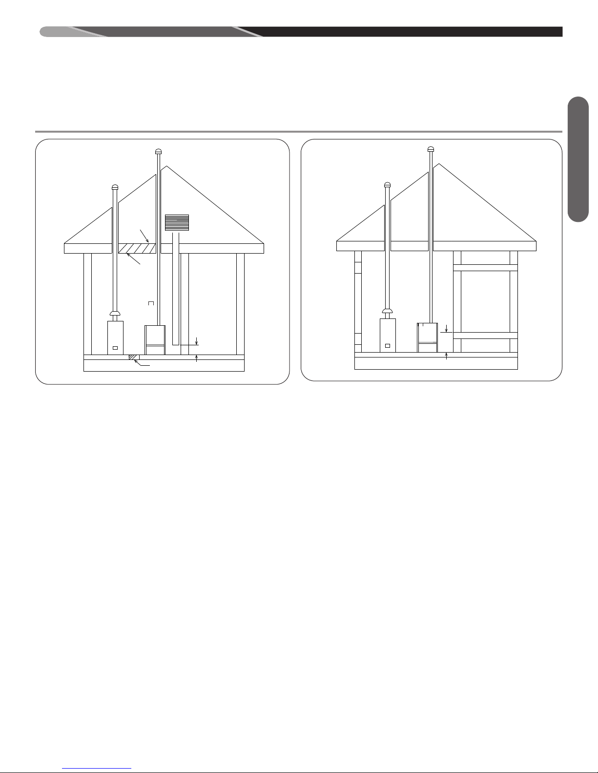
FIGURE 7
IR FROM ATTIC/CRAWL SPACE
A
A. 1 Square inch for each 3,000 BTUH of the total input rat-
ing of all equipment located in the enclosure
and
B. Not less than the sum of the areas of all vent connectors
in the confined space.
If the unit is installed where there is an exhaust fan, sufficient
ventilation must be provided to prevent the exhaust fan from creating negative pressure.
It is also acceptable to run the condensate drain (or refrigerant) line access over the air intake hole as long as a 1" minimum clearance is maintained.
Combustion air openings must not be restricted in any manner.
IMPORTANT: When indoor combustion air is used, the inlet air
opening at the furnace must be protected from accidental blockage.
ST-A1227-02-00
FIGURE 8
OUTSIDE AIR USING A
ORIZONTAL INLET & OUTLET
H
ST-A1227-03
IMPORTANT: If the furnace is in a location with an exhaust fan,
there must be sufficient ventilation to prevent the exhaust fan
from creating a negative pressure in the room.
Combustion air openings must NOT BE RESTRICTED in any
manner.
CONSULT LOCAL CODES FOR SPECIAL REQUIREMENTS.
B: Method 3
For the optimum in quiet operation, attic air may be brought directly to the furnace.
IMPORTANT: In applications using Method 3 for combustion air,
the attic must be ventilated by gable or soffit vents.
Combustion Air
15
 Loading...