

Page 1
------------------------------------------------------ -----------------------------
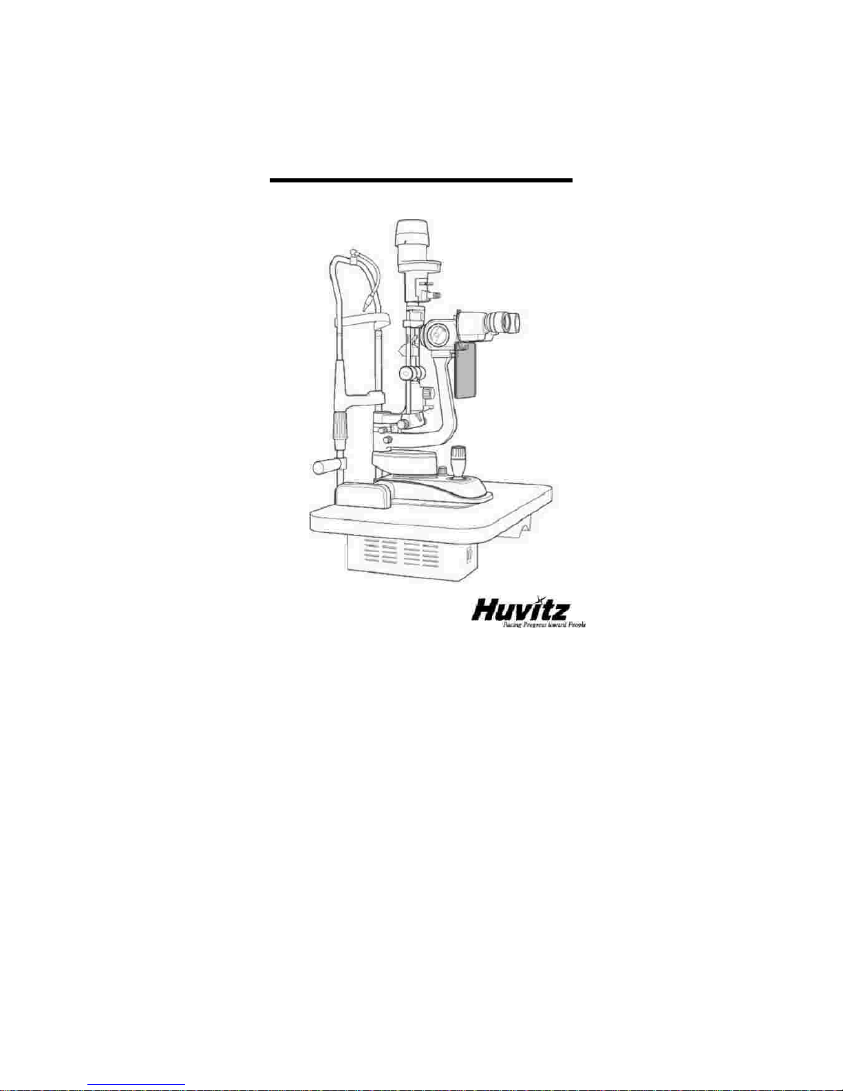
SLIT LAMP HS
-7000
1
Operator’s Manual
SLIT LAMP MICROSCOPE HS
-7000
Page 2

2
SLIT LAMP HS
-7000
-------------------
--
--------------------------------------------------
------------
I
MPORTANT NOTICE
!
WARNING
Potential electrom agnetic or o ther interference between medical equipments and other
devices being operated together in the same environmental may expert an ad verse
influence on f
unctioning of the medic al equipment.
Non-medical equipm ents not in
co mpliance with the requirements of EN 60601
-
1 and EN 6060 1
-
1
-
2 should not be
used to gether in the same environmental as the medical equipm ents
This equipment has been tested and found t
o comply with the limits for medical devices in
IEC 60601
-
1
-
2:2001.
These limits are designed to provide reasonable protection against
harmful interference in a typical medical installation
Power Cord
For use of equipment in rated voltage less than 125V
ac
, minimum
6A
, Type
SJT or
SVT,
18/3AW G
, 10 A
, max 3.0 m
long:
One end with Hospital Grade Type, NEMA 5
-
15P
other
end with appliance coupler. For use of equipment in rated voltage less than 2 50Vac
,
minimum
6A
, Type
SJT o r
SVT,
18/3AW G
, 10 A
, max 3.0m
long:One e nd
terminated
with
blade attachment
plug (
HAR) Type , NEM A 6
-
15P.
This product may malfunction due to electromagnetic waves caused by portable personal
telephones, transceivers, radio
-
controlled toys, etc. Be sure to avoid having objects such as,
which
affect this product, brought near the product.
The information in this publication has been carefully checked and is believed to be entirely
accurate at the time of publication. HUVITZ assumes no responsibility, ho we ver, for possible
errors or omissio ns,
or for any consequences resulting from the use of the ormation
co ntained herein.
Page 3

------------------------------------------------------ -----------------------------
SLIT LAMP HS
-7000
3
HUVITZ reserves the right to make changes in its products or product specifications at any
time and without prior notice, and is not required to update this docume ntation
to reflect such
changes.
©2009HUVITZ Co ., Ltd.
689-3, Geumjeong
-
dong, Gunpo
-
si, Gyeonggi
-
do,
435-862, Republic of Korea
All rights are reserved.
Under copyright laws, this manual may not be copied, in whole o r in part, without the prior
w
ritten conse nt of HUVITZ Co., Ltd.
Document
Number: 9000ENGJ201
-
A.
Page 4

4
SLIT LAMP HS
-7000
-------------------
--
--------------------------------------------------
------------
Contents
1.
Introduction
................................
................................
................................
.......6! .2.
Safety Information
................................
................................
..............................
63.Features & Operating Condition
................................
................................
......144.
Standard Components
................................
................................
.....................
165.Accessories
................................
................................
................................
.....176.
Composition
................................
................................
................................
....187.
Installation
................................
................................
................................
.......248.
Trial Operations
................................
................................
...............................
289.Main Features
................................
................................
................................
..2910.
Ordinary Maintenance
................................
................................
......................
30
1.1.
Indication for use
...........................
1.2.
Classification
................................
................................
............................
6
2.1.
Introduction
................................
................................
..............................
7
2.2.
Safety Symbols
................................
................................
........................
8
2.3.
Environment factors
................................
................................
................
10
2.4.
Safety Precautions
................................
................................
..................
12
3.1.
Brief Description
................................
................................
.....................
14
3.2.
Operating Condition
................................
................................
................
14
7.1.
Assembling the Instrument
................................
................................
......
24
오류
책갈피가
정의되어
있지
않습니다
Page 5

------------------------------------------------------ -----------------------------
SLIT LAMP HS
-7000511.
EMC Information
................................
................................
..............................
34
12.
Electric Diagram
................................
................................
...............................
43
13.
Technical Specifications
................................
................................
..................
44
14.
Service Information
................................
................................
..........................
46
10.1.
Halogen Projection bulb
................................
................................
..........
30
10.2.
Protection fuses replacement
................................
................................
...3210.3.
Cleaning & Disinfection
................................
................................
...........
33
11.1.
Guidance and manufacturer’s declaration
–
electromagnet
ic emissions
......3411.2.
Guidance and manufacturer’s declaration
–
electromagnetic immunity
.......3511.3.
Guidance and manufacturer’s de
claration
–
electromagnetic immunity
.......3711.4.
Recommended separation distances between portable and mobile RF
communications equipment and the EUT
................................
..............................
39
11.5.
Immunity and Compliance Level
................................
..............................
40
11.6.
Guidance and manufacturer’s declaration
–
electromagnetic immunity
.......4115. P
articular Information
………………………………………………………………………
.4
8
Page 6
6
SLIT LAMP HS
-7000
-------------------
--
--------------------------------------------------
------------
1.
Introduction
1.1.
Indication for
use (
intended use)
1.2.
Classification
!
CAUTION
The SLIT LAMP, HS
-
7000 is intended for use in eye examination of the ant eye
segments, from the cornea epithelium to the posterior capsule. It is u
sed to aid in the
diagnosis of diseases or trauma which
affects
the structural properties of the anterior
eye segment.
-
Protection against electric shock: Class I
-
Applied Parts: Type B applied parts.
-
Protection against harmful ingress of wa
ter: Ordinary, IPX0
-
Degree of safety in the presence of a flammable anesthetics mixture with air
or with oxygen or with nitrous oxide: Not suitable for use in the presence of a
flammable anesthetics mixture with air or with oxygen or with nitrous oxide.
-Mode of operation: Continuous
-
Light Hazard protection Classification: Group 2 by ISO15004
-
2:2007
-
Stationary:
Do not try to move this equipment without help.
This microscope is
heavy and should maintain stationary. Always get two persons to help lift this
uni
t
Federal law restricts this device to sale by or on the of a physician
Page 7
------------------------------------------------------ -----------------------------
SLIT LAMP HS
-7000
7
2.
Safety Information
2.1.
Introduction
NOTE
!
WARNING
!
CAUTION
Safety is everyone
’
s responsibility. The safe use of this equipment is largely dependent
upon the installer, user, operator, and maintaine
r. It is imperative that personnel study
and become familiar with this entire manual before attempting to
install
use, clean,
service or adjust this equipment and any associated accessories. It is paramount that
the instructions contained in this manual ar
e fully understood and followed to enhance
safety to the patient and the user/operator. It is for this reason that the following safety
notices have been placed appropriately within the text of this manual to highlight safety
related information or informa
tion requiring special emphasis. All users, operators, and
maintainers must be familiar with and pay particular attention to all Warnings and
Cautions incorporated herein.
“
Warning
”
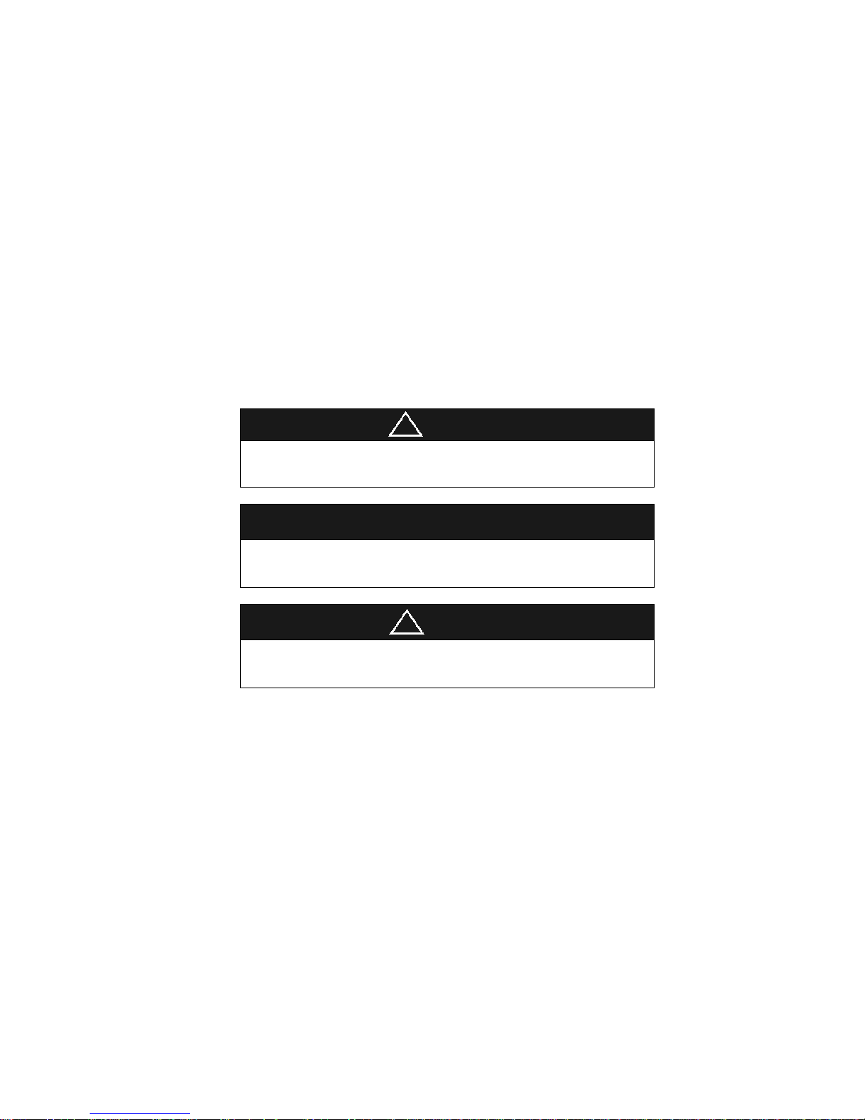
indicates the presence of a hazard that could result in severe persona
l injury,
death or substantial property damage if ignored
.
“
Note”describes information for the installation, operatio n, or maintenance of which is
important but hazard related if ignored.
“
Caution
”
indicates the presence of a hazard th at coul
d result in minor injury, or
property damaged if ignored.
Page 8
8
SLIT LAMP HS
-7000
-------------------
--
--------------------------------------------------
------------
2.2.
Safety Symbols
Save this instruction
The International
Electro technical
Commission
(IEC) has established a set of symbols
for medical electronic equipment which classify a connection or warn of any potential
hazards.
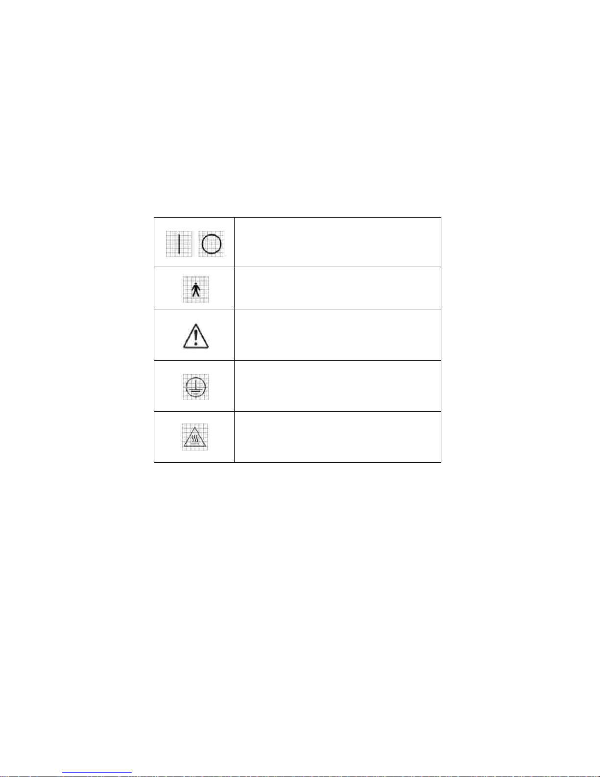
The classifications and symbols are shown below.
This applies only to the instrument that has the certification symbol printed explicitly on
the product label or sticker.
I and O on po wer switch represent ON and OFF respectively.
Type B Isolated patient connection.
This symbol identifies a safety note. Ensure you understand
the function of this control before using it. Control on
is
described in the appropriate User ’s or Service M anual.
Identifies the point where the
system safety ground is
fastened to the chassis. Protective earth connected to
co nductive parts of
Class I equipment for safety purposes.
Hot surface.
Page 9
------------------------------------------------------ -----------------------------
SLIT LAMP HS
-7000
9
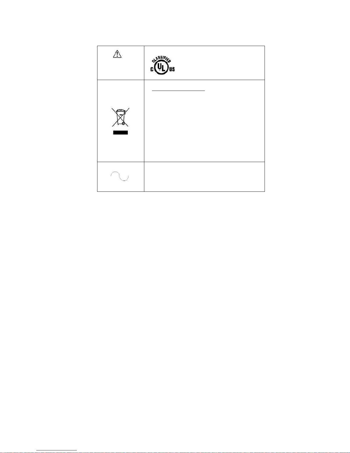
UL60601
-
1
CAN/CSA C22.2
NO.601.1
MEDICAL EUIPMENT
WITH RESPECT TO ELEC TRIC SHOCK
FIRE AND M
ECH ANICAL HAZ ARDS
ONLY IN ACCORDANCE W ITH U L
60601-1,
AND C AN/CS A
C22.2
NO.601.1
Disposal of your old applianc e
When this crossed
-
out wheeled bin
symbol is
attached to a
product it
means the
product is covered by the European
Directive 2 002/96/EC.
All e
lectrical and electronic products should be dispose d of
separately from the municipal waste stream via de signated
collection facilities appointed by the government or the local
authorities.
The correct disposal of your old appliance will help prevent
poten
tial negative consequences for the environment and
human health.
4. For more detailed information about disposal of your old
appliance, please co ntact your city office, waste disposal
service or the shop where you purchased the pro duct.
Alternating Cur
rent
Page 10
10
SLIT LAMP HS
-7000
-------------------
--
--------------------------------------------------
------------
2.3.
Environment factors
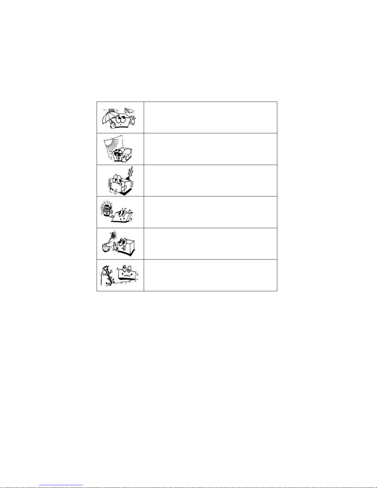
Avoid the following environments for operation or storage:
Where the equipment is exposed to water vapor.
Don’t operate
equipment
with a wet hand.
Where the equipment is exposed to direct sunlight.
Where the temperatu
re change s
extremely
.
Normal operating temperature range is from 10
C to 40
C,
Humidity is from 30% to 75%.
Altitude is from 700 to 1060hpa
Where it is near the heat equipment.
Where the humidity is extre me ly high or there i
s a ventilation
problem.
Where the equipme nt is subject to e xcessive shocks or
vibrations.
°
°
Page 11
------------------------------------------------------ -----------------------------
SLIT LAMP HS
-7000
11
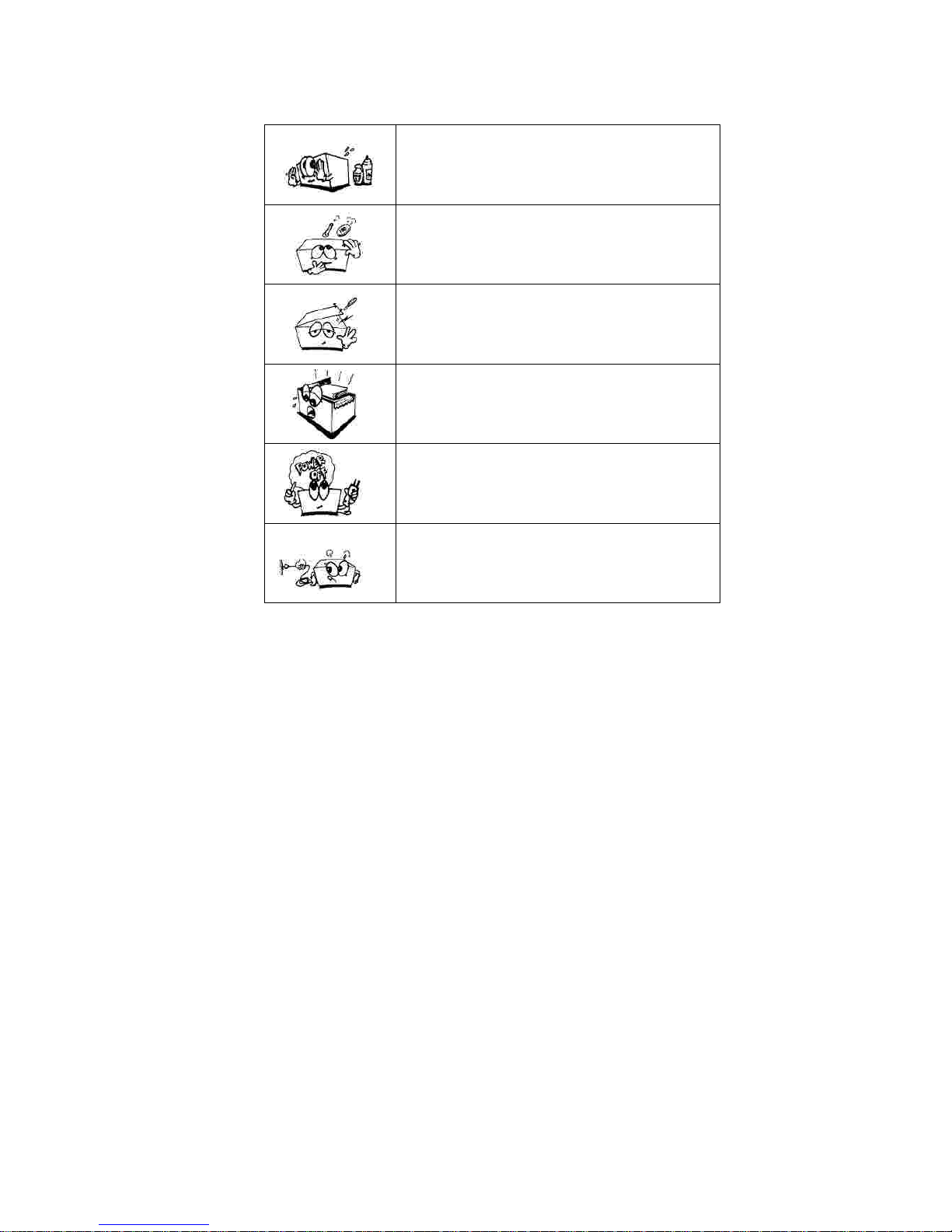
Where equipment is exposed to chemical material or
explosive gas.
Be careful not to be inserted dust, e specially, metal.
Don’t disassemble the product
or open. We aren
’
t
respo nsible for it for nothing.
Be careful no t to close the fan located on the lateral or back
side of the equipm ent.
Don’t plug the AC power c ord into the outlet before the
co nnection between devices of the equipment is co mpleted.
This can generate the defect.
Pull out the power cord with holding the plug, not the cord.
Avoid places where the ambient temperature falls below 10
or exceeds 40
for
normal operation, or below
-10or exceeds 40
(14-104
) for transportation an
d
storage. Humidity should be maintained between 30 and for normal operation,
transportation and storage. The
atmospheric pressure in
operation, transportation and
storage
is from
700
to
1060hp
a
.
℃℃℃℃℉
℉
Page 12

12
SLIT LAMP HS
-7000
-------------------
--
--------------------------------------------------
------------
2.4.
Safety Precautions
This equipment
has been developed a
nd tested according to safety standards as well
as national and international standards. This guarantees a very high degree of safety
for this device. The legislator expects us to inform the user expressively about the
safety aspects in dealing with the de
vice. The correct handling of this equipment
is
imperative for its safe operation. Therefore, please read carefully all instructions before
switching on this device. For more detailed informatio please contact our Customer
Service Department or one of ou
r authorized representatives.
1.
This equipment
must not be used (a) in an area that is in danger of explosions
and (b) in the presence of flammable, explosive, or vo tile solvent such as
alcohol, benzene or similar chemicals.
2.
Do not put or use this device
in humid rooms. Humidity should be maintained
between 30 and 75% for normal operation. Do not expose the device to water
splashes, dripping water, or sprayed water. Do not place containers containing
fluids, liquids, or gases on top of any electrical equi
pment or devices.
3.
The equipment must be operated only by, or under direct supervision of a
properly trained and qualified person.
4.
Modifications of this equipment
may only be carried out by Huvitz
’
s service
technicians or other authorized persons.
5.
Custom
er maintenance of this equipment
may only be performed as stated in
the User
’
s Manual and Service Manual. Any additional maintenance may only
be performed by Huvitz
’
s service technicians or other authorized persons.
6.
The manufacturer is only responsible fo
r effects on safety, reliability, and
performance of this equipment when the following requirements are fulfilled: (1)
The electrical installation in the respective room corresponds to the
specifications stated in this manual and (2) This equipment is used
, operated,
Page 13

------------------------------------------------------ -----------------------------
SLIT LAMP HS
-7000
13
And
maintained according to this manual and Service Manual.
7.
The manufacturer is not liable for damage caused by unauthorized tampering
with the device(s). Such tampering will forfeit any rights to claim under
warranty.
8.
This equipment
may on
ly be used together with accessories supplied by
Huvitz
’
s. If the customer makes use of other accessories, use them only if their
safe usability under technical safety aspects has been proved and confirmed
by Huvitz or the manufacturer of the accessory.
9.Only persons who have undergone proper training and instructions are
authorized to install, use, operate, and maintain this equipment.
10.
Keep the User
’
s Manual and Service Manual in a place easily accessible at all
times for persons operating and maintaining
the equipment.
11.
Do not force cable connections. If a cable does not connect easily, be sure that
the connector (plug) is appropriate for the
receptacle
(socket). If you cause any
damage to a cable connector(s) or receptacle(s), let the damage(s) be repair
ed
by an authorized service technician.
12.
Please do not pull on any cable. Always hold on to the plug when
disconnecting cables.
13.
Before every operation, visually check the equipment for exterior mechanical
damage(s) and for proper function.
14.
Do not cover a
ny ventilation grids or slits.
15.
Immediately turn off and unplug any equipment that gives off smoke, sparks,
strange noises, or odors.
16.
Power Supply Cord set (international)
-
(Detachable) Rated 10 A, 250 V. Plug
type CEE 7/VII, Connector type IEC 60320/C13
, and Cord type H05VV
-
F3G,
min. 0.75 mm2, 3
-
conductor terminating in molded
-
on grounding type
attachment plug. <HAR> marked on the cord. Maximum 4.0 m long
.
Page 14

14
SLIT LAMP HS
-7000
-------------------
--
--------------------------------------------------
------------
3.
Features & Operating Condition
3.1.
Brief Description
3.2.
Operating Condition
The
device works like all slit lamps:
Stereomic
roscopic
examination of the eye under the slit light.
Microscopic
examination of the ocular fundus and posterior vitreou body (using
h
ruby’
s lens).
These devices are designed for use by ophthalmologists and
optometrists (
within the
realms of their respect
ive professions) for specific diagnostic
procedures (
bio-microscopic examination of the eye)
As long as the slit lamp is in its original package it can be exposed to the
following environmental conditions for up to 15 weeks ship
ping and storage
without risk of damage:
-
Temperature
range:
from –10
C to +40
C;-Relative humidity range: from 30% to75%;
The device is made to operate under the following environmental conditions:
-
Temperature
range:
from +1
0
C to +
40C;-Relative humidity range: from 30%
to
75%;
The device
neither
generates nor receiv
es electromagnetic interference when used
near other equipment. Therefore, no preventive or corrective measures are required
-
-
l
l
˚˚˚
˚
Page 15

------------------------------------------------------ -----------------------------
SLIT LAMP HS
-7000
15
!
CAUTION
Because prolonged intense light exposure c an damage the retina, the use of the device
for ocular examination should not be unne
cessarily prolonged, and the brightness
setting should not exceed what is needed to provide cl visualization of the target
structures. This device should be used with filters that eliminate UV
radiatio n
(
<400nm
) and
, whene ver possible, filters that elim
inate short
-
wavelength blue
light (<420nm).
The retinal exposure dose for a photochemical hazard is a product of the radiance and
the exposure time. If the value of radiance were reduc in half, twice the time wo uld
be needed to reach the maximum exposure
limit.
While no acute optical radiation hazards have been identified for slit lamps, it is
recommended that the intensity of light directed into patient
’
s e ye be limited to the
minimum level which is necessary for diagnosis. Infants, aphakes and perso
ns with
diseased eyes will be at greater risk. The risk may also increased of the person being
examined has had any exposure with the same instrument or any other ophthalmic
instrument using a visible light source during the previous 24 hours. This will ap
ply
particularly if the eye has been exposed to retinal photography
Page 16

16
SLIT LAMP HS
-7000
-------------------
--
--------------------------------------------------
------------
4.
Standard Components
The instrument is delivered in package. Taking it out the package, make sure that
none of the following parts is missing.
A table top(N.B. the table top isn
’t supplied with the slit lamp for twin table) on
which are placed: A SMPS box(15) including the main switch & a warning
light (13), Two sliding guides for the base with orthogonal movements(17), A
sliding plate for the position device(19), A drawer(16);
A
base with orthogonal movements.
A microscope with either dual magnification or a
system (
31) including
eyepieces.
An optical group of the slit projector.
A head rest
module (
59).Amicroscope
arm (
45).
This manual.
A set of accessories including; two
wheels for the sliding guides(18); a setting
rod(43); a protective cover(46); a spare bulb 12V 30W ogen bulb(53); two
protection fuses(48); a breath screen(19); a chin
-
rest paper(47);a hole
cover(45); a power cable; two patient
’
s handles(50)
lllllll
l
Page 17
------------------------------------------------------ -----------------------------
SLIT LAMP HS
-7000
17
5.
Accessori
es
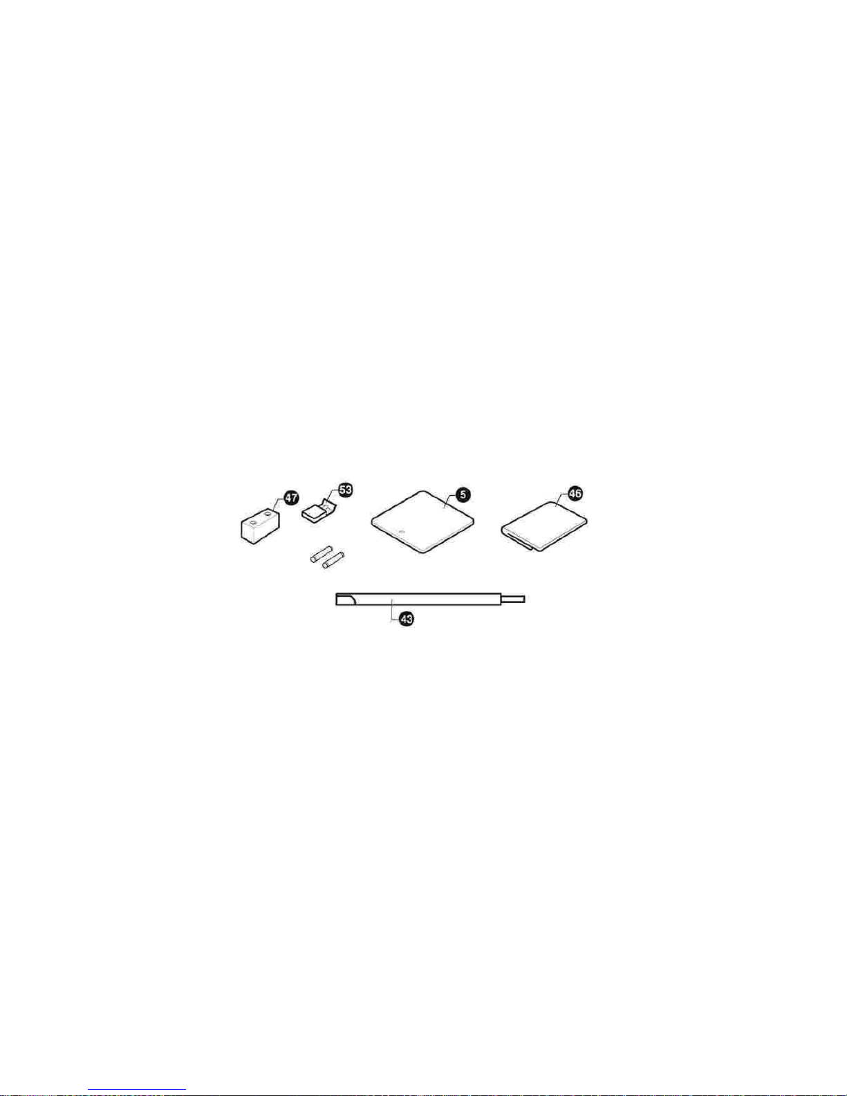
The following standard accessories are provided with the instrument;
protection cover(46)
a setting rod(43)
spare bulbs
12V 30W Halogen
bulb (
53)
chin-rest paper(47)
spare fuses
250Vac T2.0AL
a breath screen(5)
power cable
lllllll
[ Figure 1. Accessories ]
Page 18

18
SLIT LAMP HS
-7000
-------------------
--
--------------------------------------------------
------------
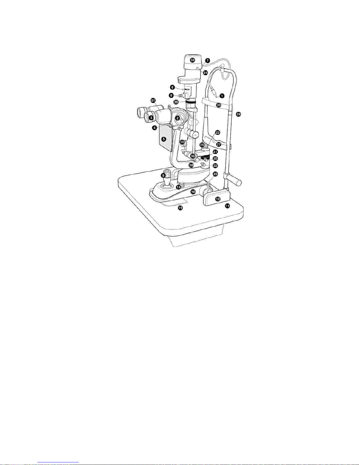
6.
Composition
1)
Fixation point
2)
Control lever for changing enlargement
3)
Removable eye
-
pieces
4)
Knob for clamping the breath screen
5)
Breath screen
6)
Control handle for the slit rotation 90
-0-907)
Connecting plug of the projector lamp
8)
Knurled ring for filters insertion
9)
Joystick fo
r lateral, longitudinal and vertical movements(x y z)
10)
Base with orthogonal movements
11)
Shaped tabletop
12)
Warning light indicating the ignition of the SMPS is on
13)
Main switch
& Warning light
14)
Luminosity selector
15)
SMPS box
16)
Drawer
17)
Toothed guides
18)
Wheel protection cra
nkcases
19)Sliding plate
20)
Knob to lock the projector
21)
Scale for the projector position
22)
Knob to lock the arm of the microscope
23)
Hole cover
24)
Knurled
knob
to lock the Lamp housing
25)
Control handle
for the vertical setting of the chin
-
rest
Page 19

------------------------------------------------------ -----------------------------
SLIT LAMP HS
-7000
19
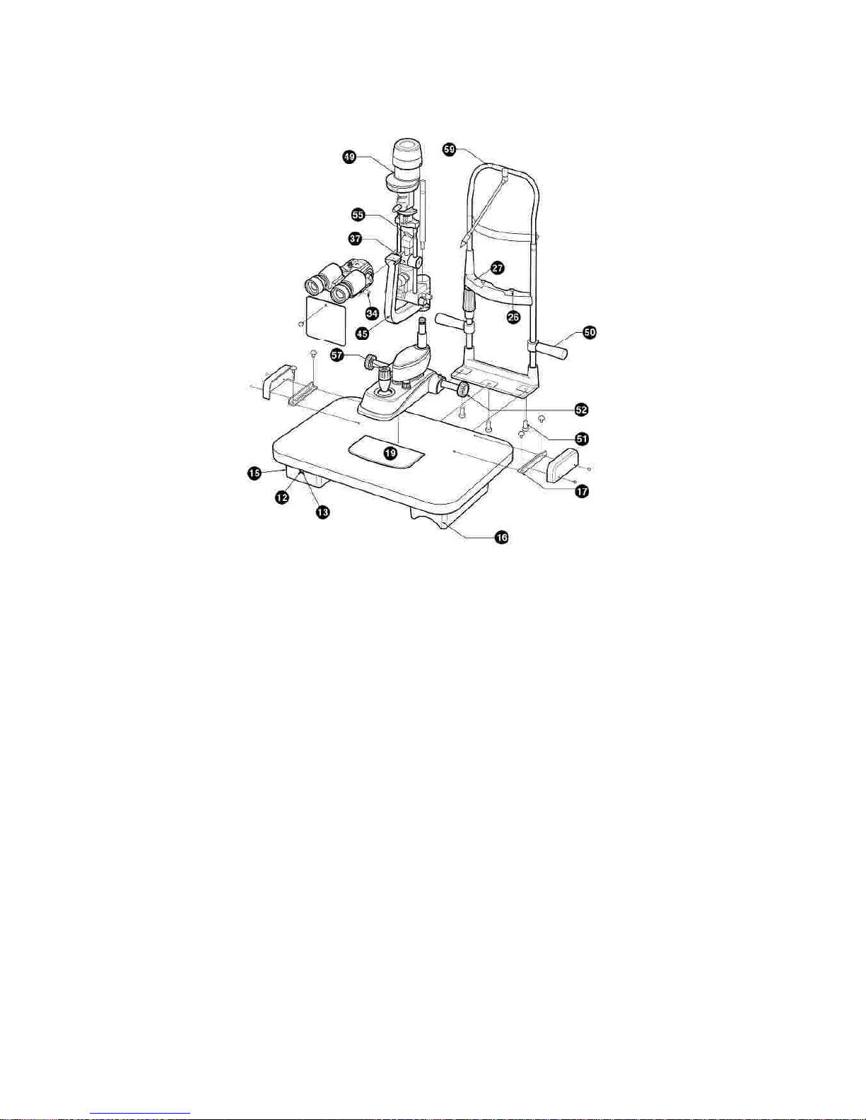
26)
Locking pins for chin rest pa
per
27)
Chin rest
28)
Knobs to change the slit width
29)
Pointer for the eye positioning
30)
Foreh
eadRest
31)
Microscope
32)
Lamp socket
33)
Knob to lock the base of the instrument
34)
Knob to lock the microscope
35)
Control handle for horizontal tilting
36)
Control lever for vertical tilting
37)
Microscope position stop
38)
Graduated ring 90
-0-
90 determining the inclination of the slit during rotation
39)
Lamp cover
40)
fuse slots
41)
Connecting plug
42)
Fixation point connector
43)
Setting rod
44)
Microscope separation knob
45)
Microscope arm
46)
Protection cover
47)
Chin rest papers
48)Guide screw
49)
An optical group of the slit projector
50)
Patient
’
s handle
51)
Head
rest fastening screw
52)
Wheel
53)
Halogen bulb 12V 30W
Page 20

20
SLIT LAMP HS
-7000
-------------------
--
--------------------------------------------------
------------
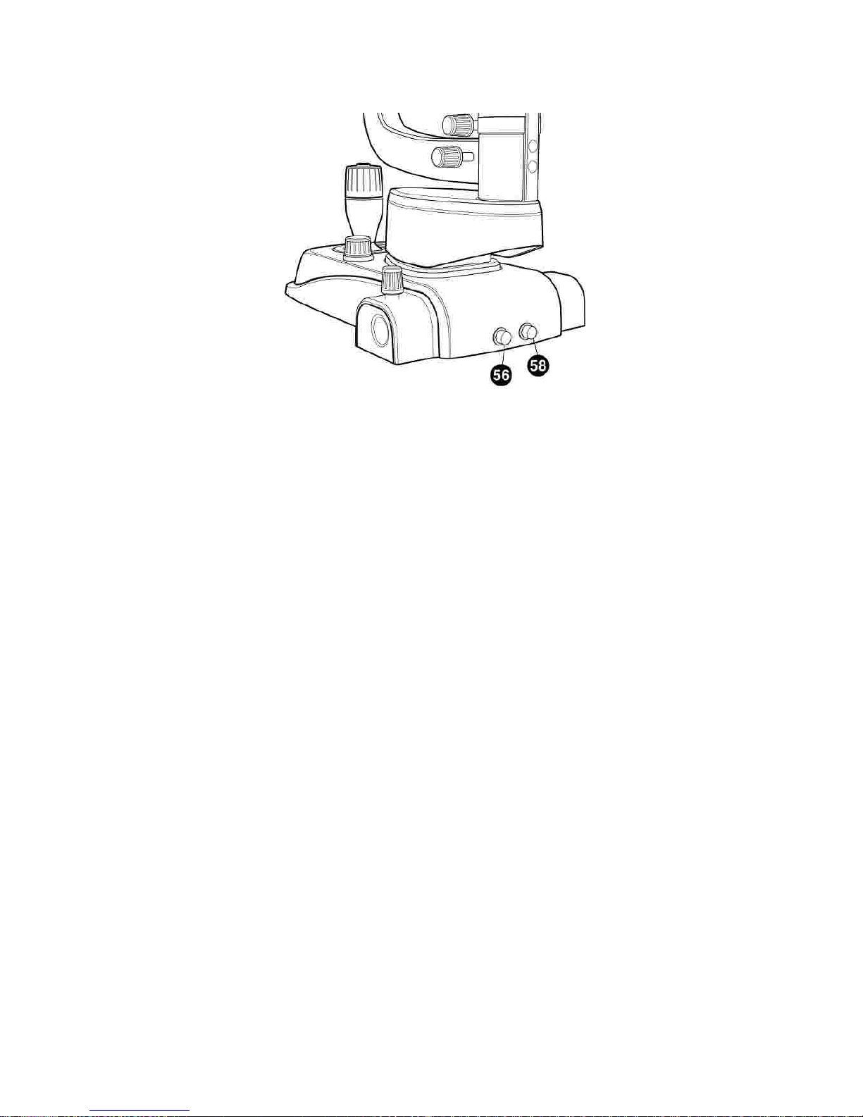
54)
Bulb fastening knob
55)
Mirror
56)
Capture connector ( For the image system)
57)
Capture switch
58)
Luminosity selector connector ( Connect the Luminos
ity selector to the
SMPS)
59)
Head rest module
Page 21
------------------------------------------------------ -----------------------------
SLIT LAMP HS
-7000
21
[ Figure 2. Composition I ]
Page 22
22
SLIT LAMP HS
-7000
-------------------
--
--------------------------------------------------
------------
[ Figure 3. Composition
Ⅱ
]
Page 23
------------------------------------------------------ -----------------------------
SLIT LAMP HS
-7000
23
[ Figure 4. Composition
Ⅲ
]
Page 24
24
SLIT LAMP HS
-7000
-------------------
--
--------------------------------------------------
------------
7.
Installation
NOTE
7.1.
Assembling the Instrument
The appliances are always supplied with exce llent packaging to be able to stand up to
all kinds of transport and standard storage conditio ns. Please co ntact the suppliers if
an
y irregularities are found in the appliance due to transport after unpacking
l
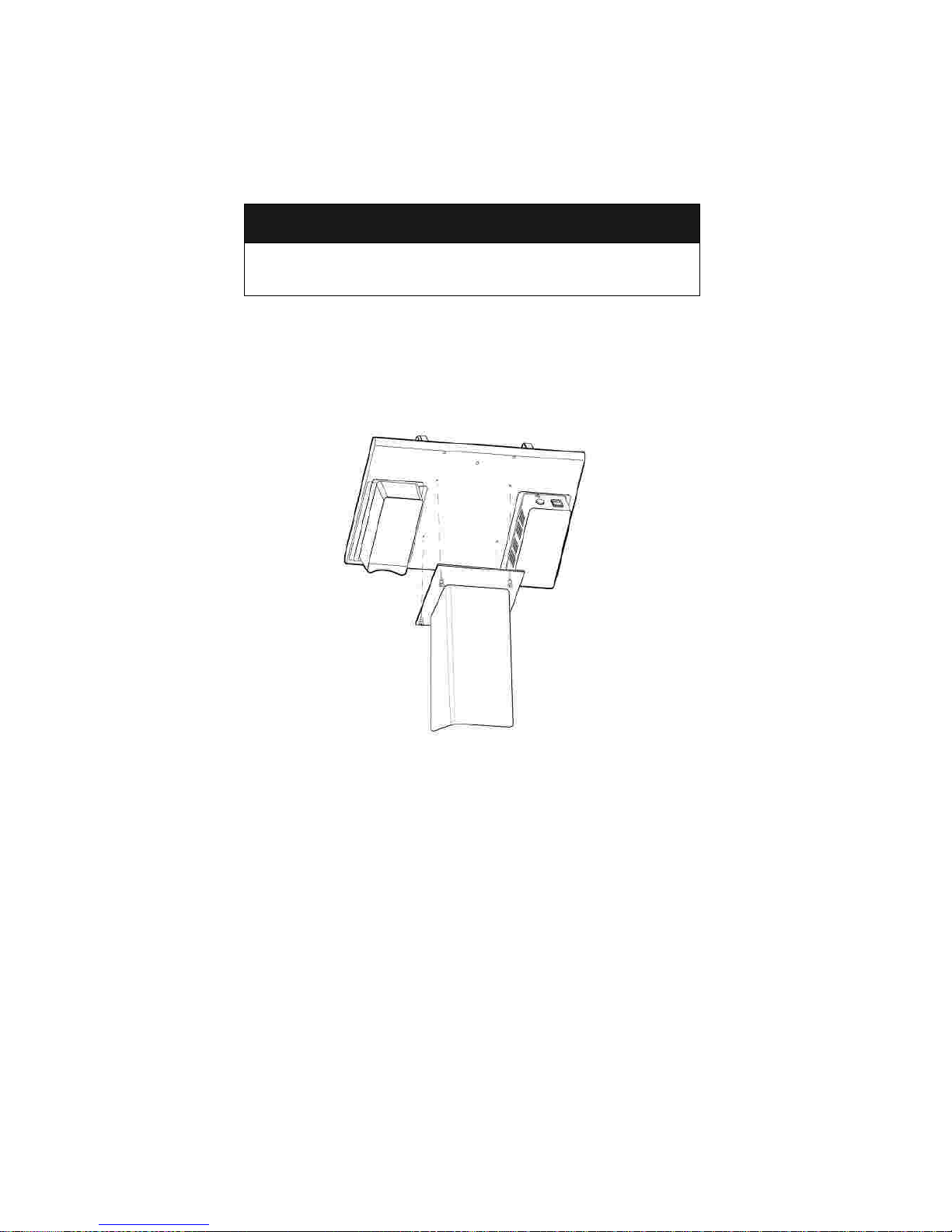
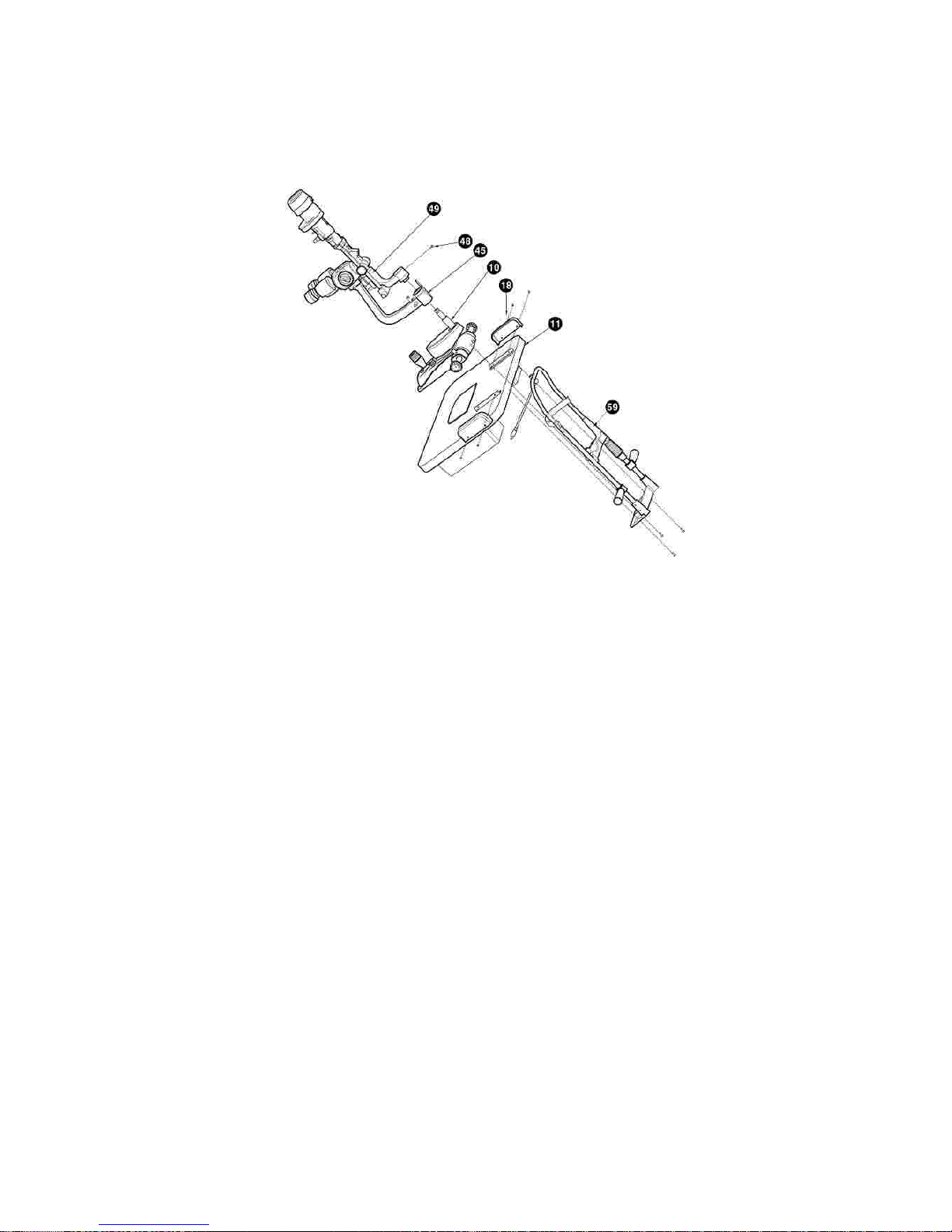
Put the table top on a very stable support. Block the wo parts together by
tightening the screws
[ Figure
5
. Table Assembling ]
Page 25
------------------------------------------------------ -----------------------------
SLIT LAMP HS
-7000
25
llllPlace the
head rest
module (
59)
and make sure
that its holes fit together with
those of the table top. Tighten the screw with the
screw driver
Place the base with orthogonal movements on the guides situated on the
upper part of the table top, checking that the wheels are in line. Then Place the
crankcase (
59)
and make sure that its holes fit together with those of the
t
oothed
guides
(
17)
. Tighten the screw with the
screw driver(+)
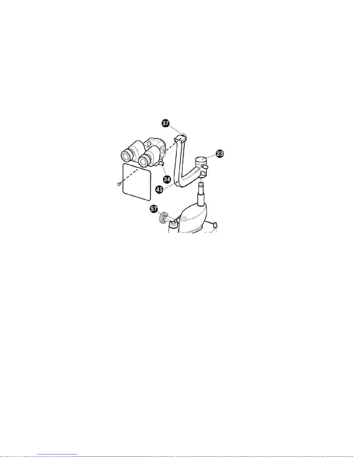
Assemble the microscope
arm (
45) on the
Base with orthogonal move
ments
(
10).
Assemble
an
optical group of the slit
projector
(
49) on the
Base with orthogonal
[ Figure
6
. As
sembling the instrument I]
Page 26
26
SLIT LAMP HS
-7000
-------------------
--
--------------------------------------------------
------------
movements
(
10). Then tighten the Guide screw with the screw driver(
-)Put the microscope(31) in the right position making sure that it is placed well in
the stop(37); then tighten it with the knob(34)situate th
e right side of the
microscope.
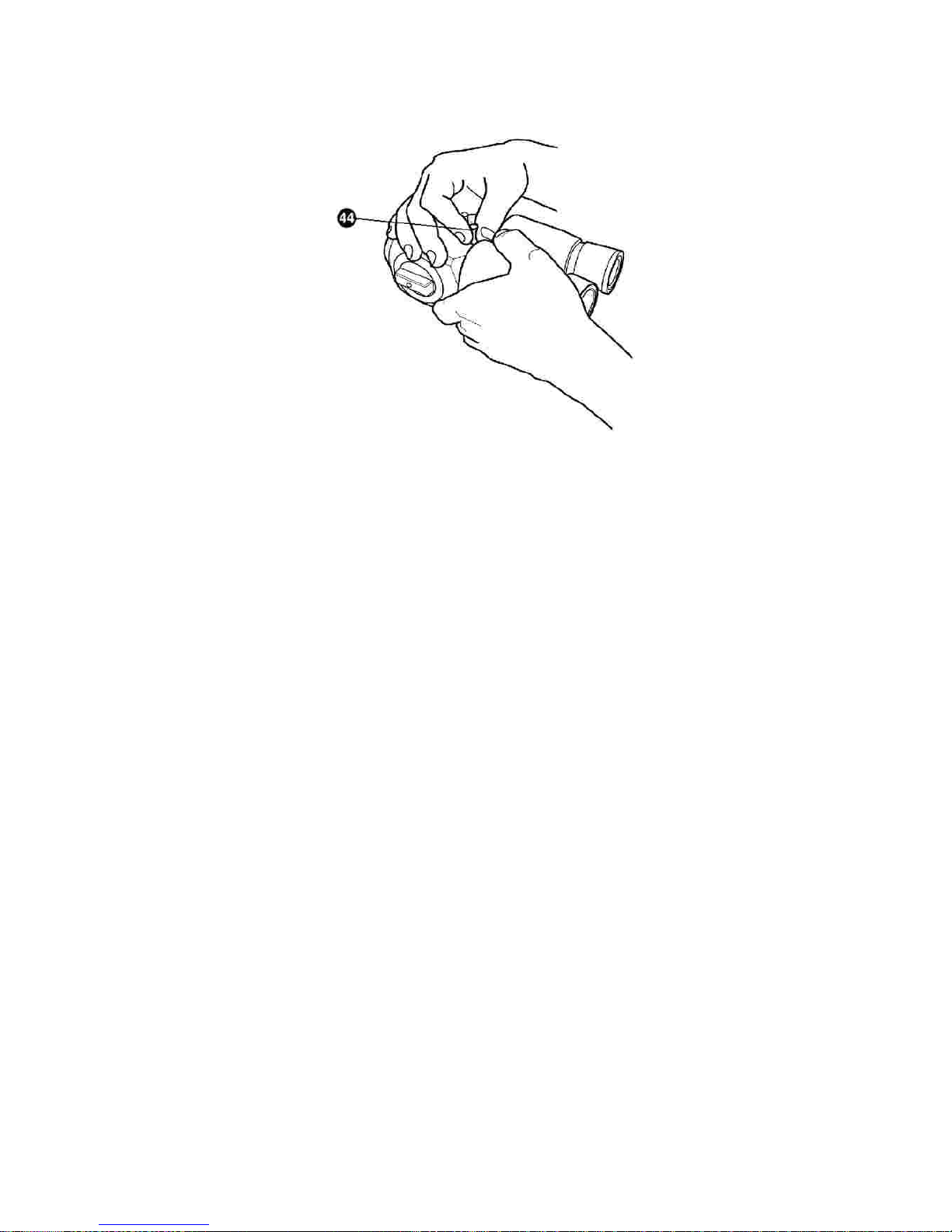
Fasten the breath screen(5) with the knob(4)
Insert the connecting cable into the socket.
lll
Page 27
------------------------------------------------------ -----------------------------
SLIT LAMP HS
-7000
27
[ Figure
7
. Assembling the instrument
Ⅱ
]
Page 28

28
SLIT LAMP HS
-7000
-------------------
--
--------------------------------------------------
------------
8.
Trial Operations
llllllAssemb
le
the
chin-rest
paper (
47)
on the chin
-
rest (27).
Let the patient sit down comfortable with hi
s chin on the chin
-
rest and his
forehead against the forehead
-
rest.
Lift or lower the chin
-
rest by moving the handle (25) so that the patient
’
s eyes
are in line with the notches on the chin
-
rest(29)
Switch the instruments on, press the
switch (
13). You w
ill see the warning light
on (12).
Adjust the luminous intensity by moving the selector(14)
Frame and focus the eye to be examined by moving the lever(9)
Page 29

------------------------------------------------------ -----------------------------
SLIT LAMP HS
-7000
29
9.
Main Features
Principal operative characteristics of the instrument:
Observation without settli
ng or tiring and rapid change of enlargements.
Base with cross
-
wise movement (which can be stopped) commanded by a
single joystick for all adjustments(x y z)
Stereomicroscopic
observation of the eye with enlargements 6X
-
10X-16X-25X-40X (
5 enlargements mo
del).
Tilting 5
-10-15-20Microscopy
of the
back part
and of
the posterior vitreous body by means of the
Hruby lens or a contact options
. (
Goldman lens).
Observation of the eye and valuation of the position of contact lenses in a
fluorescent light.
Tonomet
ry with Goldman tonometer.
Measurement of the cornea diameter and contact lenses.
Survey which reveals the axis of the contact lens, tha to the possible reading
of the rotation angle of the slit which includes all the meridians.
lllllllll
˚˚˚
˚
Page 30
30
SLIT LAMP HS
-7000
-------------------
--
--------------------------------------------------
------------
10.
Ordinary Maintenanc
e
NOTE
10.1.
Halogen Projection bulb
!
WARNING
!
CAUTION
The repairs illustrated below should all be carried out with the power cable
disconnected from the main supply plug. Please contact the suppliers for any other
problems that cannot be resolved by the operations des ibed below.
Please turn off t
he power switch befo re replacing lamps. Please place lamps after
cooling down. The heated lamp may burn your fingers.
Don’t touch any other parts of glass tube with the bare fingers. Fingerprints, if any,
must be wiped o ff from the glass tube with
alcohol
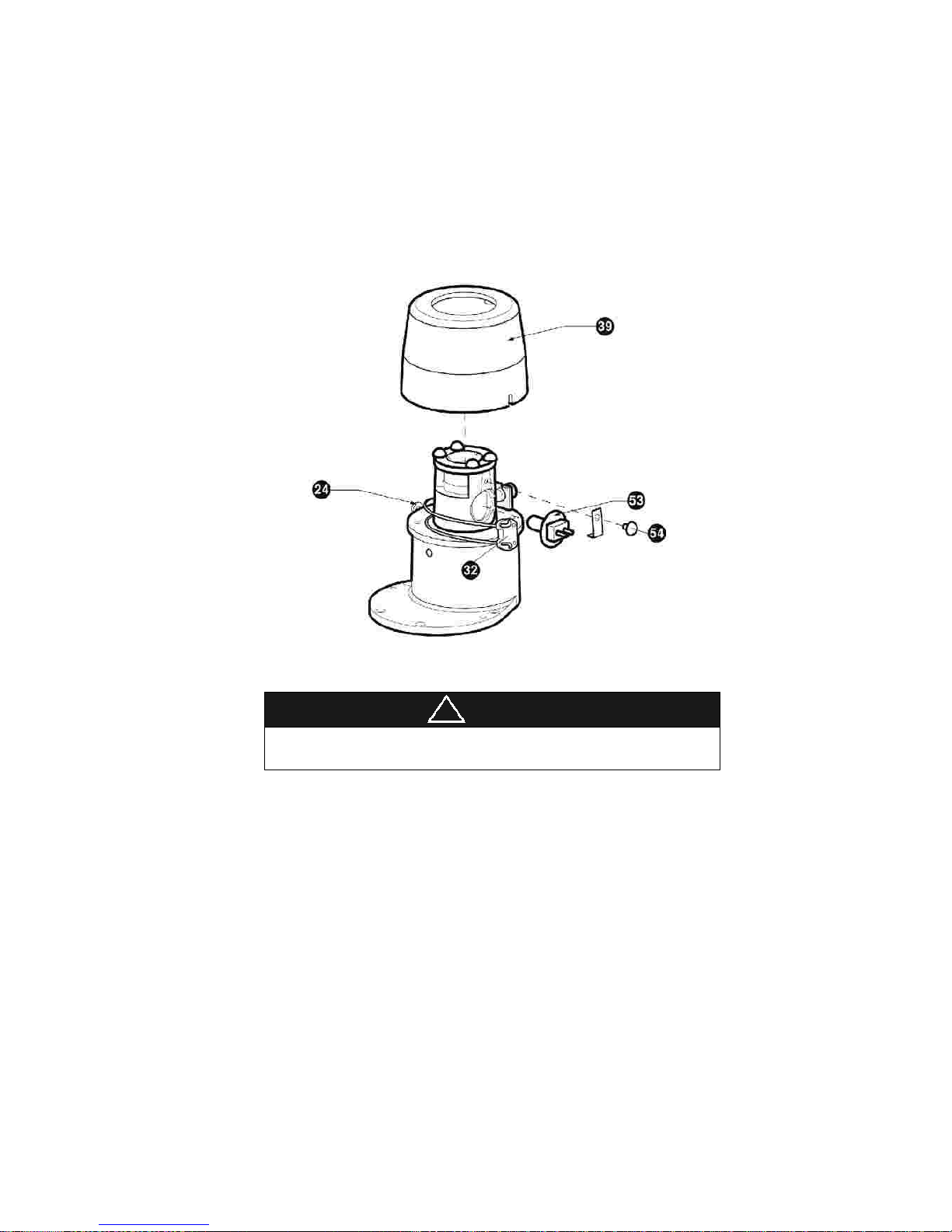
To replace the Halogen projection bulb proceed as follow.
Before doing anything else, disconnect the plug from the main supply socket;
Remove the screws with the driver(24), Remove the cover(39),
Remove the
Lamp socke
t
(32) from the bulb stems;
Bulb fastening knob
(54) to loosen the bulb stop
Remove the burnt out bulb; be careful , it could be very hot;
lllll
Page 31
------------------------------------------------------ -----------------------------
SLIT LAMP HS
-7000
31
!
WARNING
lll
Replace it with a new one(12V30W Halogen) using the pl tic envelope(never
touch the bulb whit fingers)
Fasten the
bulb with the knob
Make sure that the stems of the bulb are completely inserted; insert the plug in
the main supply socket
Don’t Touch to the Lamp House, During the Operation.
It’s Heating up.
[ Figure
8
. Replace Halogen bulb ]
Page 32
32
SLIT LAMP HS
-7000
-------------------
--
--------------------------------------------------
------------
10.2.
Protection fuses replacement
!
CAUTION
To replace the fuse
s proceed as follows:
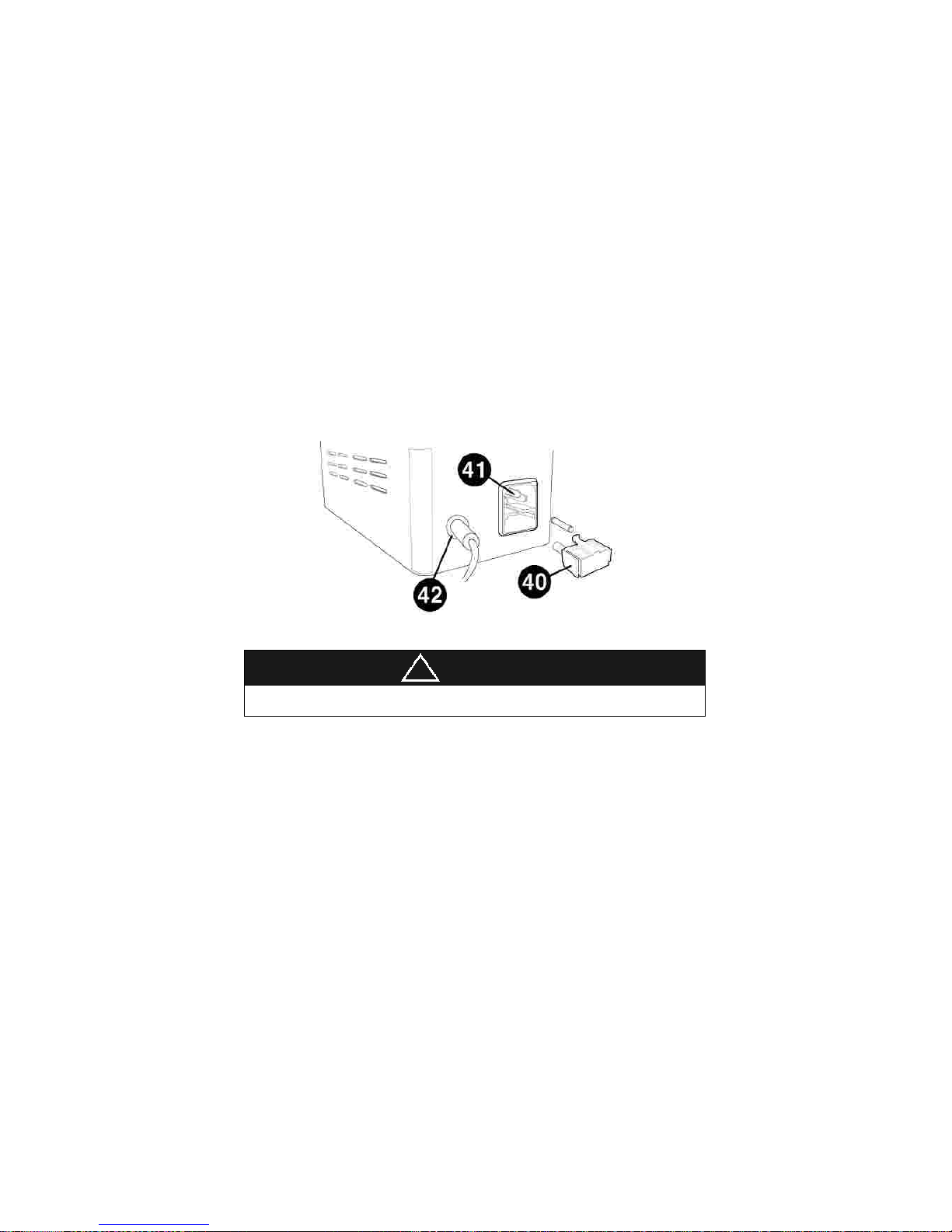
The protection fuses are placed on the back of the SMPS, and inserted power
socket. Before doing anything else, disconnect the plu from the main supply
socket
Remove the burned
-
out fuses
Substitute the fuses and check
Replace th
e plug in the main supply socket.
lll
l
Replace fuses with the same rating and type(250Vac, T2.0AL)
[ Figure
9
. Replace the fuse ]
Page 33

------------------------------------------------------ -----------------------------
SLIT LAMP HS
-7000
33
10.3.
Cleaning & Disinfection
llTo keep the device clean, apply clinical alcohol and cidex or cidex plus on a soft
cloth and scrub the body and the probe onc
e a month. Do not use lacquer,
thinner, ethylene, or the oxidizing substance.
If the instrument is not in use, dust must be kept away by covering the
instrument with the supplied plastic cover. Dust accumulating during the
functioning of the instrument m
ust be periodically removed with a very soft cloth
or with a small pump.
Page 34

34
SLIT LAMP HS
-7000
-------------------
--
--------------------------------------------------
------------
11.
EMC Information
11.1.
Guidance and manufacturer
’
s declaration
–
electromagnetic
emissions
Immunity test
Compliance
Electromagnetic environment
-
guidance
The EUT is intended for use in the electromagnetic environment specified below.
The customer or
the user of the EUT should assure that it is used in such an
environment.
RF Emissions
CISPR 11
Group 1
The EUT uses RF energy only for its
internal function. Therefore, its RF
emissions
are very low and are not likely
to cause any interference in nearby
electronic equipment
RF Emissions
CISPR 11
Class B
The EUT is suitable for use in ail
establishments, including domestic
establishments and those directly
connected to the public low
-
voltage power
supply network that supplies buildings
used for domestic purposes
Harmonic
emissions
IEC 61000
-3-2Class A
Voltage
fluctuations/
Flicker emissions
IEC 61000
-3-3Complies
Page 35

------------------------------------------------------ -----------------------------
SLIT LAMP HS
-7000
35
11.2.
Guidance and manufacturer
’
s declaration
–
electromagnetic
i
mmunity
Immunity test
IEC 60601
Test level
Compliance
level
Electromagnetic
environ
ment -guidance
The EUT is intended for use in the electromagnetic environment specified below.
The customer or the user of the EUT should assure that it is used in such an
environment.
Electrostatic
discharge (ESD)
IEC 61000
-4-2 ±6kV Contact
±8kV air
±6kV Contact
±8kV air
Floors should be wood,
concrete or ceramic tile.
If floors are covered with
synthetic material, the
relative humidity should
be at least 30%.
E
lectrical fast
transient/burst
IEC 61000
-4-4 ±2kV for power
supply lines
± 1kV for
input/output
lines
±2kV for power
supply lines
± 1kV for
input/output
lines
Mains power quality
should be that of a
typical commercial or
hospital environment.
S
urge
IEC 61000
-4-5 ±1kV
differential
mode
±2kV common
mode
±1kV differential
mode
±2kV common
mode
Mains power quality
should be that of a
typical commercial or
hospital environment.
Voltage dips,
short
interruptions and
voltage
variations
on powe
r supply
input lines
IEC 61000
-4-
11
<5% U?
(>95% dip in
U?)
for 0.5cycle
40% U?
(60% dip in
U? )
for 5 cycle
70% U?
(30% dip in U?)
for 25 cycle
<5% U?
(>95% dip in U?)
for 0.5cycle
40% U?
(60% dip in U? )
for 5 cycle
70% U?
(30% dip in U?)
for 25 cycle
<5% U?
(<95% dip in
Mains power quality
should be that of a
typical commercial or
hospital environment. If
the user of the EUT
image
intensifier require
continued operation
during power mains
interruptions,
it is recommended
that
the
Page 36
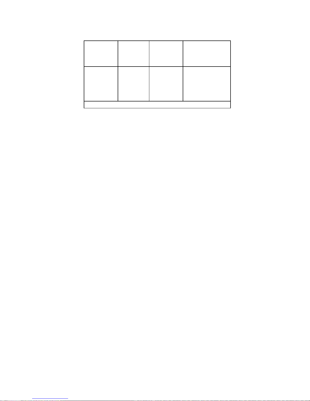
36
SLIT LAMP HS
-7000
-------------------
--
--------------------------------------------------
------------
<5% U?
(<95% dip in
U? )
for 5 s
U? )
for 5 s
EUT image intensifier be
Powered
from an
uninterruptible power
supply or a battery.
Power frequency
(50/60Hz)
magnetic field
IEC 61000
-4-8 3 A/m
3 A/m
Power frequency
magnetic fields should
be at levels character
ristic of a typical loca
tion
in a typical commercial
or hospital environment.
NOTE U? is the a.c. mains voltage prior to application of the test level.
Page 37
------------------------------------------------------ -----------------------------
SLIT LAMP HS
-7000
37
11.3.
Guidance and manufacturer
’
s declaration
–
electromagnetic
immunity
Immunity
test
IEC
60601
test
level
Complianc
e
level
Electromagnetic environment
-
guidance
Recommended separation distance
The EUT is intended for use in the electromagnetic environment specified below.
The customer or the user of t
he EUT should assure that it is used in such an
environment.
Conducted
RF
IEC
61000
-4-6 Radiated
RF
IEC
61000
-4-3 3 Vrms
150
kHz to
80MHz
3 V/m
80
MHz to
2.5GHz
3 Vrms
150 kHz to
80MHz
3 V/m
80MHz to
2.5GHz
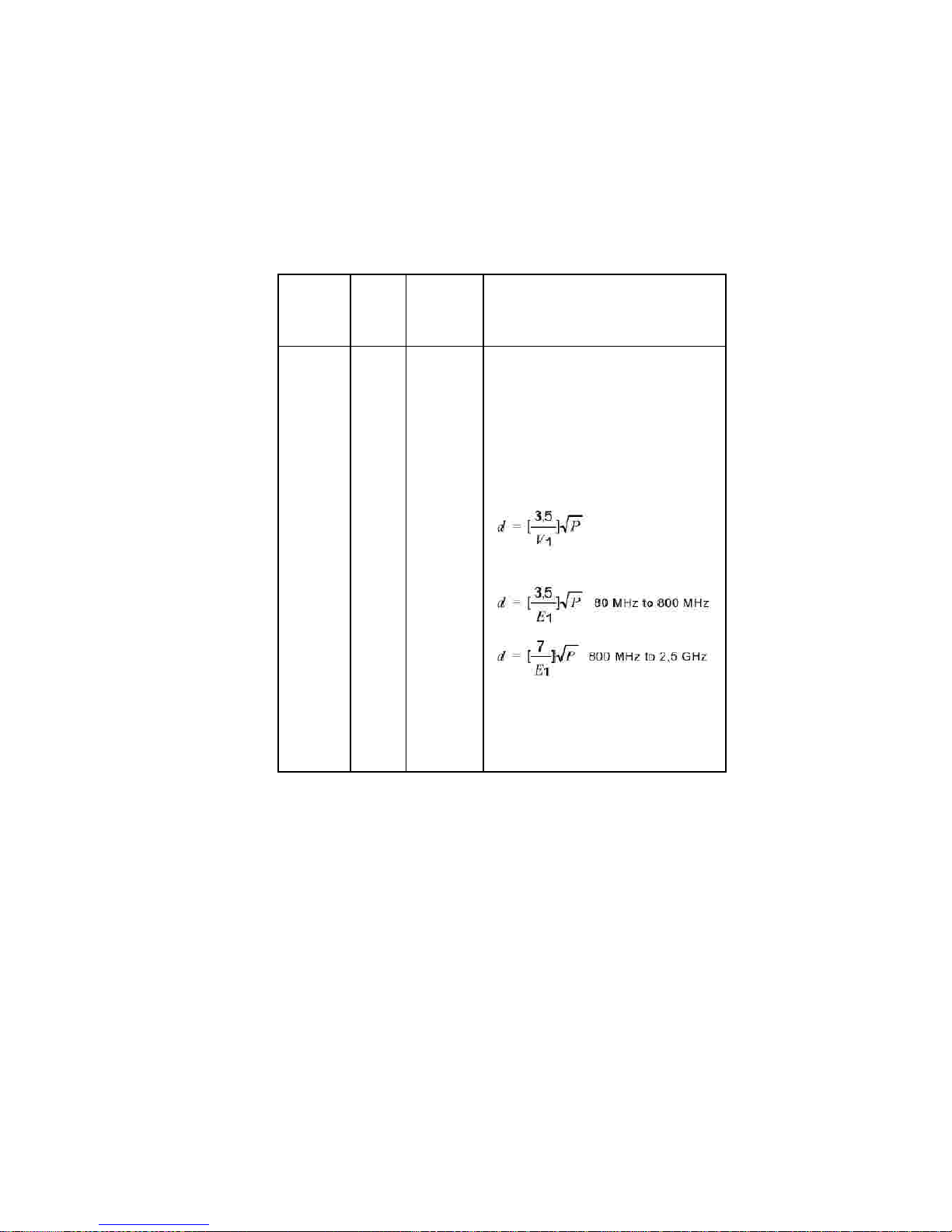
Portable and mobile RF communications
equipment should be used no closer to any
part of the EUT, including cables, than the
recommended separation distance
calculated from the equation
applicable to
the frequency of the transmitter.
where P is the maximum output power
rating of the transmitter in watts (W)
according to the transmitter manufacturer
Page 38
38
SLIT LAMP HS
-7000
-------------------
--
--------------------------------------------------
------------
and d is the recommended separatio
n
distance in meters (m).
Field strengths from fixed RF transmitters,
as deter
-
mined by an electromagnetic site
survey,
a
should be less than the compliance level in
each frequency range.
b
Interference may occur in the vicinity of
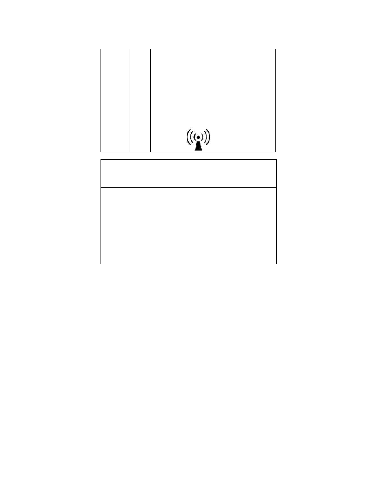
equipment marked wit
h the following
symbol :
NOTE 1) At 80MHz and 800MHz, the higher frequency range applies.
NOTE 2) These guidelines may not apply in all situatio Electromagnetic
propagation is affected by absorption and reflection from structures,
objects and
people.
a
Field strengths from fixed transmitters, such as base tations for radio
(cellular/cordless) telephones and land mobile radios, amateur radio, AM and FM
radio broadcast and TV broadcast cannot be predicted theoretically with accurac
y.
To assess the electromagnetic environment due to fixed RF transmitters, an
electromagnetic site survey should be considered. If the measured field strength in
the location in which the EUT is used exceeds the applicable RF compliance level
above, the E
UT should be observed to verify normal operation. If abnormal
performance is observed, additional measures may be necessary, such as re
-
orienting or relocating the EUT.
b
Over the frequency range 150kHz to 80MHz, field strengths should be less than
[V1] V/
m.
Page 39
------------------------------------------------------ -----------------------------
SLIT LAMP HS
-7000
39
11.4.
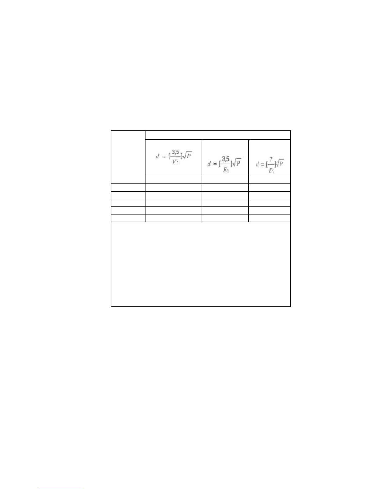
Recommended separation distances between portable and
mobile RF communications equipment and the EUT
Thisis intended for use in an electromagnetic environment which radiated RF
disturbances are controlled. The customer or the user the EUT ca
n help Prevent
electromagnetic interference by maintaining a minimum nce between portable
and mobile RF communications equipment (transmitters) the EUT as
recommended below, according to the maximum output power of the communications
equipment.
R
ated
maximum
output power
of transmitter
[W]
Separation distance according to frequency of transmitter
[m]
150kHz to 80MHz
80MHz to
800MHz
800MHz to
2.5GHz
V1=3Vrms
E1=3V/m
E1=3V/m
0.01
0.116
0.1166
0.2333
0.1
0.368
0.3687
0.7378
1
1.166
1.1660
2.3333
10
3.687
3.6872
7.3785
100
11.660
11.6600
23.333
For transmitters rated at a maximum output power not listed above, the
recommended separation distance d in metres (m)
can be estimated using the
equation applicable to th
e frequency of the transmitter, where p is the maximum
output power rating of the transmitter in watts (W) according to the transmitter
manufacturer.
NOTE 1) At 80MHz and 800MHz, the separation distance for the higher frequency
range applies.
NOTE 2)
These guidelines may not apply in all situations. Electromagnetic
propagation is affected by
absorption and reflection from structures, objects and
people.
Page 40

40
SLIT LAMP HS
-7000
-------------------
--
--------------------------------------------------
------------
11.5.
Immunity and Compliance Level
Immunity test
IEC 60601 Test
Level
Actual Immunity
Level
Compliance
Level
Conducted RF
IEC 61000
-4-6 3Vrms
150kHz to 80MHz
3Vrms
3Vrms
Radiated RF
IEC 61000
-4-3 3Vrms
80MHz to 2.5GHz
3V/m
3V/m
Page 41
------------------------------------------------------ -----------------------------
SLIT LAMP HS
-7000
41
11.6.
Guidance and manufacturer
’
s declaration
–
electromagnetic
immunity
Immunity
test
IEC 60601
test level
Compliance
level
Electromagnetic environment
-
guidance
The EUT is intended for use in the electromagnetic
environment specified below.
The customer or the user of the EUT should assure that it is used in such an
electromagnetic environment.
Conducted
RF
IEC
61000
-4-6 Radiated
RF
IEC
61000
-4-3 3 Vrms
150 kHz to
80MHz
3 V/m
80 MHz to
2.5GHz
3 Vrms
150 kHz to
80MHz
3 V/m
80MHz to
2.5GHz
The EUT must be used only in a
shielded location with a minimum RF
shielding effectiveness and, for each
c
able that enters the shielded
location with a minimum RF shielding
effectiveness and, for each cable that
enters the shielded location
Field strengths outside the shielded
location from fixed RF transmitters,
as determined by an
electromagnetic site su
rvey, should
be less than 3V/m.
a
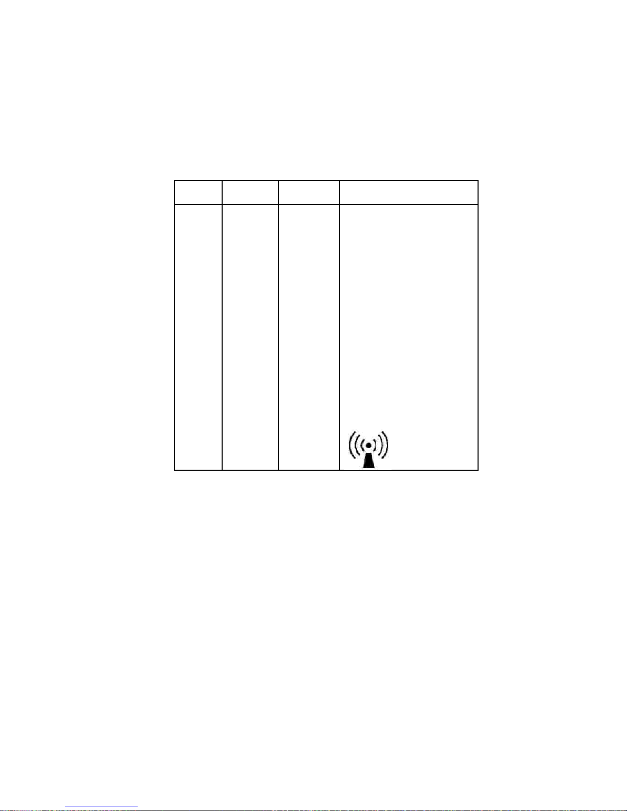
Interference may occur in the vicinity
of equipment marked with the
following symbol:
Page 42

42
SLIT LAMP HS
-7000
-------------------
--
--------------------------------------------------
------------
NOTE 1) These guidelines may not apply in all situatio Electromagnetic
propagation is affected by absorpti
on and reflection from structures, objects and
people.
NOTE 2) It is essential that the actual
shielding effectiveness and filter
attenuation of the shielded location be
verified to assure that they meet the
minimum specification.
a
Field strengths from
fixed transmitters, such as base stations for radio
(cellular/cordless) telephones and land mobile radios, amateur radio, AM and FM
radio broadcast and TV broadcast cannot be predicted theoretically with
accuracy. To assess the electromagnetic environment
due to fixed RF
transmitters, an
electromagnetic site survey should be considered. If the measured field strength
outside the shielded location in which the EUT is used exceeds 3V/m, the EUT
should be observed to verify normal operation.
If abnormal per
formance is observed, additional measures may be necessary,
such as relocating the EUT or using a shielded location with a higher RF
shielding effectiveness and filter attenuation.
Page 43
------------------------------------------------------ -----------------------------
SLIT LAMP HS
-7000
43
12.
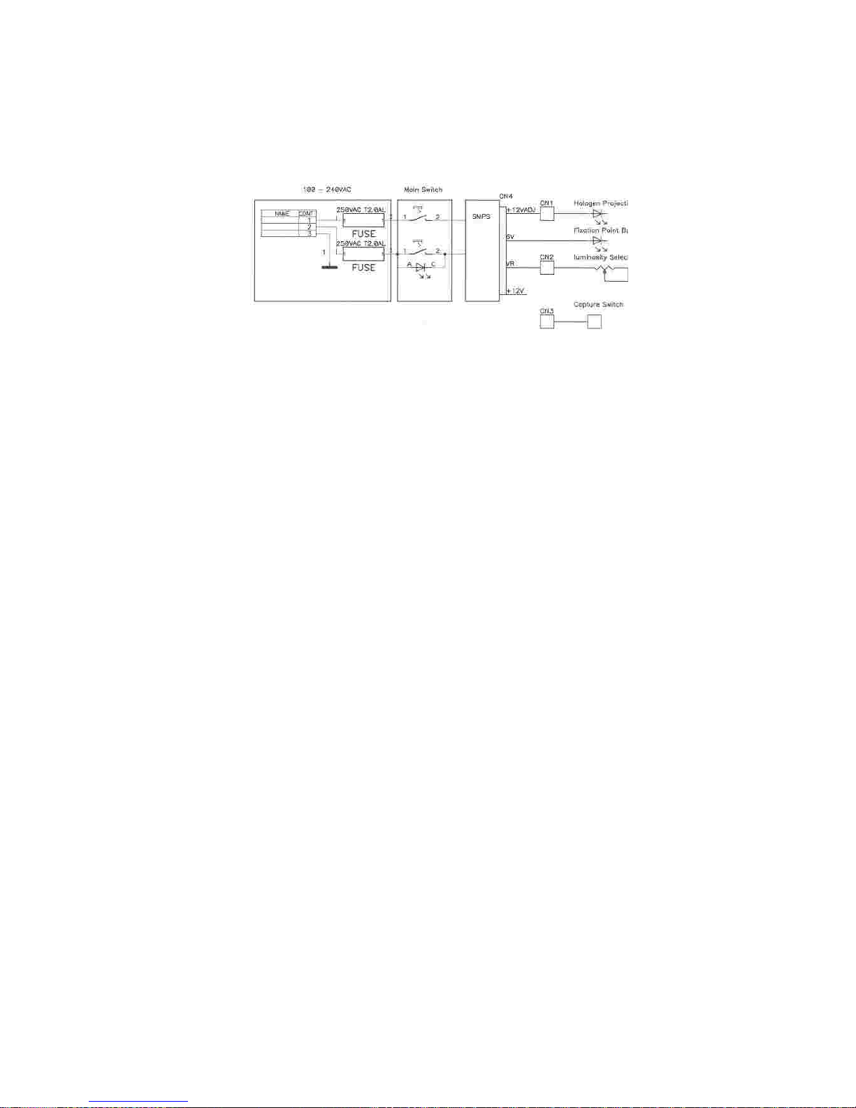
Electric Diagram
Page 44

44
SLIT LAMP HS
-7000
-------------------
--
--------------------------------------------------
------------
13.
Technical Specifications
MICROSCOPE
- HS-7000
(5x)
SLIT ILLUMINATION
Type
Galilean converging binocular
Magnification
5 positions rotation drum
Eyepiece
12.5x
(Option 10x)
Total magnification
6x, 10x, 16x, 25x, 40x(12.5x eyepiece )
or 5x, 8x, 12x, 20x, 32x( 10x eyepiece )
Real field of view
38.5, 24.0, 15.0, 9.0,6.0 mm
Interpupillary adjust
55-80 mm
Slit length
0.3-12 mm(continuous)
Slit width
0-12 mm(continuous)
Slit projection
1x
Aperture diaphragms
0.3/1/3/5/9/12 mm
Filters
cobalt blue, red
-
free, gray and heat
-
absorption
Slit rotatio
n0˚
~180˚continuous
Angle of incidence
0˚, 5˚, 10˚, 15˚, 20˚Patient
’
s eye/mirror
surface working
distance
80 mm
Page 45

------------------------------------------------------ -----------------------------
SLIT LAMP HS
-7000
45
BASE
Vertical Movement
Min. 28mm
Longitudinal Movement
Min. 78mm.
Lateral Movement
Min. 98mm
Fine base Movement
Min. 10mm
Power supp
ly
100~240 V AC 50/60HZ 2.0A
Power consumption
70VA
Instrument Voltage
12V DC
Haloge
n
Projection
bulb
12V 30W
Fixation point
LED
3.4V 20mA
Page 46

46
SLIT LAMP HS
-7000
-------------------
--
--------------------------------------------------
------------
14.
Service Information
How to contact service :
If there are any problems with the equipment, please
f
ollow the
steps be low:
First of all, refer to the 10. Maintenanc e and 11 . Troubleshooting sections according
to the problem that you are enco untered. And then fo llow the suggested
sequences
.
If the problem persists, please c
ontact
the local distributor
in your pro
vince or country
at first. Before calling to the local distributor, you
’
d better check the se information such as
Model and Serial Numbers. To do so, fill up the
following
table as soon as you
purchase our produc t. You can loo k up these
information
at any
time. The serial
number is found on the back of this unit. The serial number is unique to this unit.
Yo u should retain this manual as a permanent record of your purchase. Please retain
your purchase receipt as your proof of purchase.
If you can
’
t contact with your local distributor, you c an directly
get in touch with the
service
department
of the HUVITZ using the phone number and the address written
in
the belo w table.
lll
l
Date of Purchase:
Dealer
’
s Name:
Dealer Address:
Dealer Phone No. :
Model No.:
Serial No.:
Page 47

------------------------------------------------------ -----------------------------
SLIT LAMP HS
-7000
47
How to Contact
HUVITZ Co., Ltd
Wri te us at:
Tel
Fax
URL
http
://www.
huvitz
.co
me-
mail: hs
-
support
@huvitz.com
HUVITZ Co ., Ltd.
Huvitz B/D, 6 89
-
3 Geumjeo ng
-
dong
Gunpo-si Gyeonggi
-
do, So uth Korea
435-862
: +82-31-442-8868
: +82-31-442-8619
:
Page 48
48
SLIT LAMP HS
-7000
-------------------
--
--------------------------------------------------
------------
15.
Particular Information
15.1.
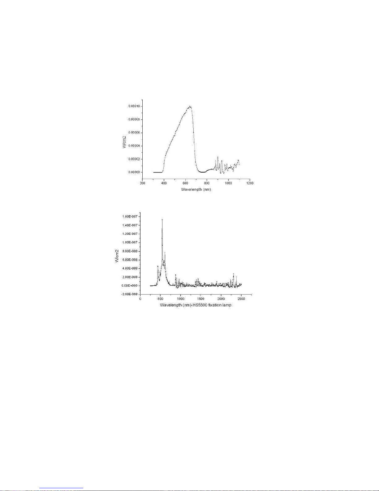
Relative spectral output graph
(1)
Halogen Lamp
(2)
Fixation Lamp
Page 49
------------------------------------------------------ -----------------------------
SLIT LAMP HS
-700049N
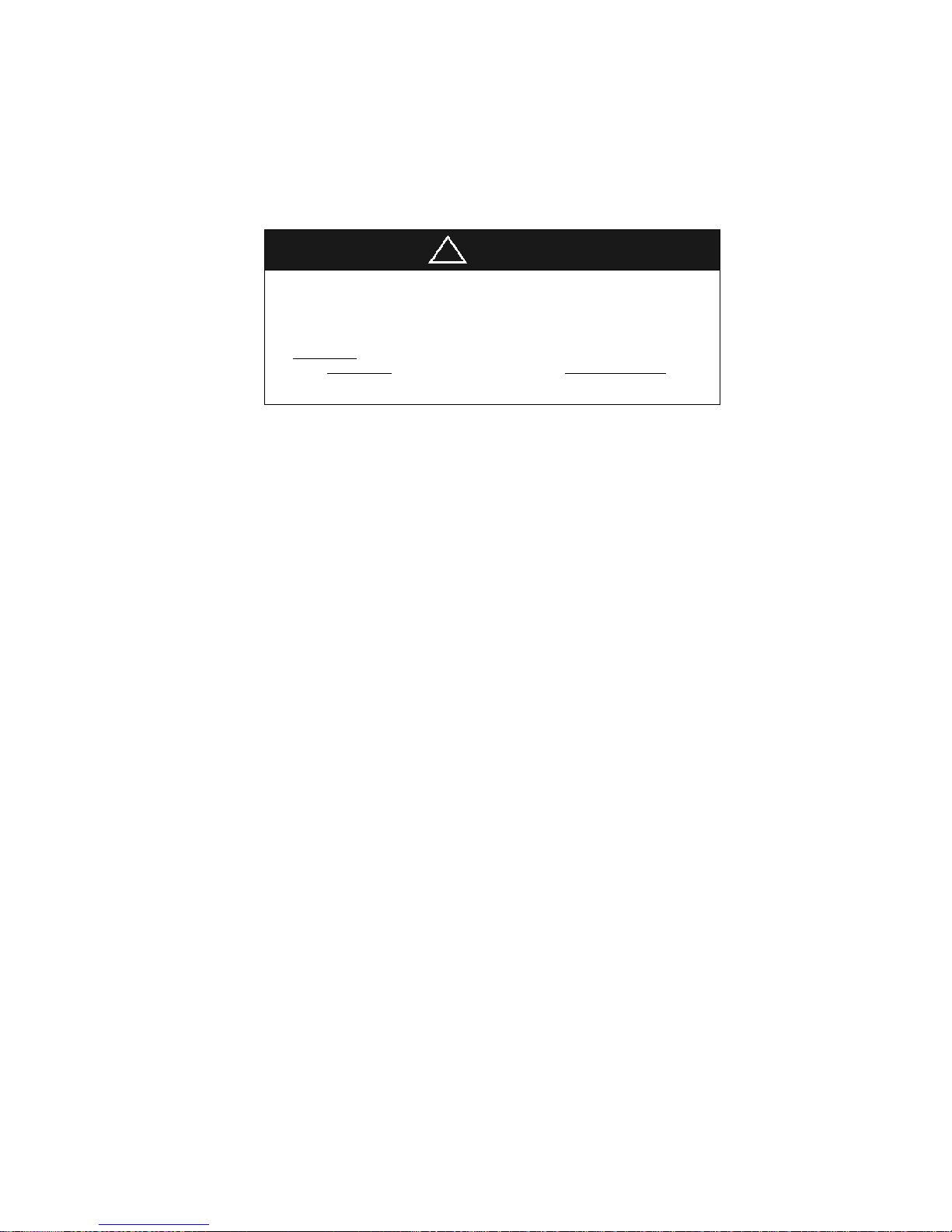
ote: this graph be shown for the beam after it exist the instrument,
when the instrument is operating at
maximum
ligh
t intensity and
maximum aperture.
!
CAUTION
“CAUTION
–
The light emitted from this instrument is potentially
hazardous. The longer the duration of exposure, the greater the risk of
ocular damage. Exposure to light from this instrument operated
at maximum ou
tput will exceed the safety guideline after
_80seconds
__
(e. g.
80
seconds
for source halogen lamp,
151057
seconds
for
fixation lamp,).”
 Loading...